WO2012108461A1 - 浸炭用鋼、浸炭鋼部品、及び、その製造方法 - Google Patents
浸炭用鋼、浸炭鋼部品、及び、その製造方法 Download PDFInfo
- Publication number
- WO2012108461A1 WO2012108461A1 PCT/JP2012/052854 JP2012052854W WO2012108461A1 WO 2012108461 A1 WO2012108461 A1 WO 2012108461A1 JP 2012052854 W JP2012052854 W JP 2012052854W WO 2012108461 A1 WO2012108461 A1 WO 2012108461A1
- Authority
- WO
- WIPO (PCT)
- Prior art keywords
- steel
- carburizing
- carburized
- hot
- less
- Prior art date
- Legal status (The legal status is an assumption and is not a legal conclusion. Google has not performed a legal analysis and makes no representation as to the accuracy of the status listed.)
- Ceased
Links
Classifications
-
- B—PERFORMING OPERATIONS; TRANSPORTING
- B32—LAYERED PRODUCTS
- B32B—LAYERED PRODUCTS, i.e. PRODUCTS BUILT-UP OF STRATA OF FLAT OR NON-FLAT, e.g. CELLULAR OR HONEYCOMB, FORM
- B32B15/00—Layered products comprising a layer of metal
- B32B15/04—Layered products comprising a layer of metal comprising metal as the main or only constituent of a layer, which is next to another layer of the same or of a different material
-
- C—CHEMISTRY; METALLURGY
- C21—METALLURGY OF IRON
- C21D—MODIFYING THE PHYSICAL STRUCTURE OF FERROUS METALS; GENERAL DEVICES FOR HEAT TREATMENT OF FERROUS OR NON-FERROUS METALS OR ALLOYS; MAKING METAL MALLEABLE, e.g. BY DECARBURISATION OR TEMPERING
- C21D1/00—General methods or devices for heat treatment, e.g. annealing, hardening, quenching or tempering
- C21D1/06—Surface hardening
-
- C—CHEMISTRY; METALLURGY
- C21—METALLURGY OF IRON
- C21D—MODIFYING THE PHYSICAL STRUCTURE OF FERROUS METALS; GENERAL DEVICES FOR HEAT TREATMENT OF FERROUS OR NON-FERROUS METALS OR ALLOYS; MAKING METAL MALLEABLE, e.g. BY DECARBURISATION OR TEMPERING
- C21D1/00—General methods or devices for heat treatment, e.g. annealing, hardening, quenching or tempering
- C21D1/26—Methods of annealing
- C21D1/32—Soft annealing, e.g. spheroidising
-
- C—CHEMISTRY; METALLURGY
- C21—METALLURGY OF IRON
- C21D—MODIFYING THE PHYSICAL STRUCTURE OF FERROUS METALS; GENERAL DEVICES FOR HEAT TREATMENT OF FERROUS OR NON-FERROUS METALS OR ALLOYS; MAKING METAL MALLEABLE, e.g. BY DECARBURISATION OR TEMPERING
- C21D8/00—Modifying the physical properties of ferrous metals or ferrous alloys by deformation combined with, or followed by, heat treatment
-
- C—CHEMISTRY; METALLURGY
- C21—METALLURGY OF IRON
- C21D—MODIFYING THE PHYSICAL STRUCTURE OF FERROUS METALS; GENERAL DEVICES FOR HEAT TREATMENT OF FERROUS OR NON-FERROUS METALS OR ALLOYS; MAKING METAL MALLEABLE, e.g. BY DECARBURISATION OR TEMPERING
- C21D8/00—Modifying the physical properties of ferrous metals or ferrous alloys by deformation combined with, or followed by, heat treatment
- C21D8/06—Modifying the physical properties of ferrous metals or ferrous alloys by deformation combined with, or followed by, heat treatment during manufacturing of rods or wires
-
- C—CHEMISTRY; METALLURGY
- C21—METALLURGY OF IRON
- C21D—MODIFYING THE PHYSICAL STRUCTURE OF FERROUS METALS; GENERAL DEVICES FOR HEAT TREATMENT OF FERROUS OR NON-FERROUS METALS OR ALLOYS; MAKING METAL MALLEABLE, e.g. BY DECARBURISATION OR TEMPERING
- C21D9/00—Heat treatment, e.g. annealing, hardening, quenching or tempering, adapted for particular articles; Furnaces therefor
- C21D9/32—Heat treatment, e.g. annealing, hardening, quenching or tempering, adapted for particular articles; Furnaces therefor for gear wheels, worm wheels, or the like
-
- C—CHEMISTRY; METALLURGY
- C22—METALLURGY; FERROUS OR NON-FERROUS ALLOYS; TREATMENT OF ALLOYS OR NON-FERROUS METALS
- C22C—ALLOYS
- C22C38/00—Ferrous alloys, e.g. steel alloys
- C22C38/001—Ferrous alloys, e.g. steel alloys containing N
-
- C—CHEMISTRY; METALLURGY
- C22—METALLURGY; FERROUS OR NON-FERROUS ALLOYS; TREATMENT OF ALLOYS OR NON-FERROUS METALS
- C22C—ALLOYS
- C22C38/00—Ferrous alloys, e.g. steel alloys
- C22C38/002—Ferrous alloys, e.g. steel alloys containing In, Mg, or other elements not provided for in one single group C22C38/001 - C22C38/60
-
- C—CHEMISTRY; METALLURGY
- C22—METALLURGY; FERROUS OR NON-FERROUS ALLOYS; TREATMENT OF ALLOYS OR NON-FERROUS METALS
- C22C—ALLOYS
- C22C38/00—Ferrous alloys, e.g. steel alloys
- C22C38/005—Ferrous alloys, e.g. steel alloys containing rare earths, i.e. Sc, Y, Lanthanides
-
- C—CHEMISTRY; METALLURGY
- C22—METALLURGY; FERROUS OR NON-FERROUS ALLOYS; TREATMENT OF ALLOYS OR NON-FERROUS METALS
- C22C—ALLOYS
- C22C38/00—Ferrous alloys, e.g. steel alloys
- C22C38/02—Ferrous alloys, e.g. steel alloys containing silicon
-
- C—CHEMISTRY; METALLURGY
- C22—METALLURGY; FERROUS OR NON-FERROUS ALLOYS; TREATMENT OF ALLOYS OR NON-FERROUS METALS
- C22C—ALLOYS
- C22C38/00—Ferrous alloys, e.g. steel alloys
- C22C38/04—Ferrous alloys, e.g. steel alloys containing manganese
-
- C—CHEMISTRY; METALLURGY
- C22—METALLURGY; FERROUS OR NON-FERROUS ALLOYS; TREATMENT OF ALLOYS OR NON-FERROUS METALS
- C22C—ALLOYS
- C22C38/00—Ferrous alloys, e.g. steel alloys
- C22C38/06—Ferrous alloys, e.g. steel alloys containing aluminium
-
- C—CHEMISTRY; METALLURGY
- C22—METALLURGY; FERROUS OR NON-FERROUS ALLOYS; TREATMENT OF ALLOYS OR NON-FERROUS METALS
- C22C—ALLOYS
- C22C38/00—Ferrous alloys, e.g. steel alloys
- C22C38/18—Ferrous alloys, e.g. steel alloys containing chromium
-
- C—CHEMISTRY; METALLURGY
- C22—METALLURGY; FERROUS OR NON-FERROUS ALLOYS; TREATMENT OF ALLOYS OR NON-FERROUS METALS
- C22C—ALLOYS
- C22C38/00—Ferrous alloys, e.g. steel alloys
- C22C38/18—Ferrous alloys, e.g. steel alloys containing chromium
- C22C38/22—Ferrous alloys, e.g. steel alloys containing chromium with molybdenum or tungsten
-
- C—CHEMISTRY; METALLURGY
- C22—METALLURGY; FERROUS OR NON-FERROUS ALLOYS; TREATMENT OF ALLOYS OR NON-FERROUS METALS
- C22C—ALLOYS
- C22C38/00—Ferrous alloys, e.g. steel alloys
- C22C38/18—Ferrous alloys, e.g. steel alloys containing chromium
- C22C38/24—Ferrous alloys, e.g. steel alloys containing chromium with vanadium
-
- C—CHEMISTRY; METALLURGY
- C22—METALLURGY; FERROUS OR NON-FERROUS ALLOYS; TREATMENT OF ALLOYS OR NON-FERROUS METALS
- C22C—ALLOYS
- C22C38/00—Ferrous alloys, e.g. steel alloys
- C22C38/18—Ferrous alloys, e.g. steel alloys containing chromium
- C22C38/26—Ferrous alloys, e.g. steel alloys containing chromium with niobium or tantalum
-
- C—CHEMISTRY; METALLURGY
- C22—METALLURGY; FERROUS OR NON-FERROUS ALLOYS; TREATMENT OF ALLOYS OR NON-FERROUS METALS
- C22C—ALLOYS
- C22C38/00—Ferrous alloys, e.g. steel alloys
- C22C38/18—Ferrous alloys, e.g. steel alloys containing chromium
- C22C38/28—Ferrous alloys, e.g. steel alloys containing chromium with titanium or zirconium
-
- C—CHEMISTRY; METALLURGY
- C22—METALLURGY; FERROUS OR NON-FERROUS ALLOYS; TREATMENT OF ALLOYS OR NON-FERROUS METALS
- C22C—ALLOYS
- C22C38/00—Ferrous alloys, e.g. steel alloys
- C22C38/18—Ferrous alloys, e.g. steel alloys containing chromium
- C22C38/32—Ferrous alloys, e.g. steel alloys containing chromium with boron
-
- C—CHEMISTRY; METALLURGY
- C22—METALLURGY; FERROUS OR NON-FERROUS ALLOYS; TREATMENT OF ALLOYS OR NON-FERROUS METALS
- C22C—ALLOYS
- C22C38/00—Ferrous alloys, e.g. steel alloys
- C22C38/18—Ferrous alloys, e.g. steel alloys containing chromium
- C22C38/40—Ferrous alloys, e.g. steel alloys containing chromium with nickel
- C22C38/42—Ferrous alloys, e.g. steel alloys containing chromium with nickel with copper
-
- C—CHEMISTRY; METALLURGY
- C22—METALLURGY; FERROUS OR NON-FERROUS ALLOYS; TREATMENT OF ALLOYS OR NON-FERROUS METALS
- C22C—ALLOYS
- C22C38/00—Ferrous alloys, e.g. steel alloys
- C22C38/18—Ferrous alloys, e.g. steel alloys containing chromium
- C22C38/40—Ferrous alloys, e.g. steel alloys containing chromium with nickel
- C22C38/44—Ferrous alloys, e.g. steel alloys containing chromium with nickel with molybdenum or tungsten
-
- C—CHEMISTRY; METALLURGY
- C22—METALLURGY; FERROUS OR NON-FERROUS ALLOYS; TREATMENT OF ALLOYS OR NON-FERROUS METALS
- C22C—ALLOYS
- C22C38/00—Ferrous alloys, e.g. steel alloys
- C22C38/18—Ferrous alloys, e.g. steel alloys containing chromium
- C22C38/40—Ferrous alloys, e.g. steel alloys containing chromium with nickel
- C22C38/48—Ferrous alloys, e.g. steel alloys containing chromium with nickel with niobium or tantalum
-
- C—CHEMISTRY; METALLURGY
- C22—METALLURGY; FERROUS OR NON-FERROUS ALLOYS; TREATMENT OF ALLOYS OR NON-FERROUS METALS
- C22C—ALLOYS
- C22C38/00—Ferrous alloys, e.g. steel alloys
- C22C38/60—Ferrous alloys, e.g. steel alloys containing lead, selenium, tellurium, or antimony, or more than 0.04% by weight of sulfur
-
- C—CHEMISTRY; METALLURGY
- C23—COATING METALLIC MATERIAL; COATING MATERIAL WITH METALLIC MATERIAL; CHEMICAL SURFACE TREATMENT; DIFFUSION TREATMENT OF METALLIC MATERIAL; COATING BY VACUUM EVAPORATION, BY SPUTTERING, BY ION IMPLANTATION OR BY CHEMICAL VAPOUR DEPOSITION, IN GENERAL; INHIBITING CORROSION OF METALLIC MATERIAL OR INCRUSTATION IN GENERAL
- C23C—COATING METALLIC MATERIAL; COATING MATERIAL WITH METALLIC MATERIAL; SURFACE TREATMENT OF METALLIC MATERIAL BY DIFFUSION INTO THE SURFACE, BY CHEMICAL CONVERSION OR SUBSTITUTION; COATING BY VACUUM EVAPORATION, BY SPUTTERING, BY ION IMPLANTATION OR BY CHEMICAL VAPOUR DEPOSITION, IN GENERAL
- C23C8/00—Solid state diffusion of only non-metal elements into metallic material surfaces; Chemical surface treatment of metallic material by reaction of the surface with a reactive gas, leaving reaction products of surface material in the coating, e.g. conversion coatings, passivation of metals
- C23C8/02—Pretreatment of the material to be coated
-
- C—CHEMISTRY; METALLURGY
- C23—COATING METALLIC MATERIAL; COATING MATERIAL WITH METALLIC MATERIAL; CHEMICAL SURFACE TREATMENT; DIFFUSION TREATMENT OF METALLIC MATERIAL; COATING BY VACUUM EVAPORATION, BY SPUTTERING, BY ION IMPLANTATION OR BY CHEMICAL VAPOUR DEPOSITION, IN GENERAL; INHIBITING CORROSION OF METALLIC MATERIAL OR INCRUSTATION IN GENERAL
- C23C—COATING METALLIC MATERIAL; COATING MATERIAL WITH METALLIC MATERIAL; SURFACE TREATMENT OF METALLIC MATERIAL BY DIFFUSION INTO THE SURFACE, BY CHEMICAL CONVERSION OR SUBSTITUTION; COATING BY VACUUM EVAPORATION, BY SPUTTERING, BY ION IMPLANTATION OR BY CHEMICAL VAPOUR DEPOSITION, IN GENERAL
- C23C8/00—Solid state diffusion of only non-metal elements into metallic material surfaces; Chemical surface treatment of metallic material by reaction of the surface with a reactive gas, leaving reaction products of surface material in the coating, e.g. conversion coatings, passivation of metals
- C23C8/06—Solid state diffusion of only non-metal elements into metallic material surfaces; Chemical surface treatment of metallic material by reaction of the surface with a reactive gas, leaving reaction products of surface material in the coating, e.g. conversion coatings, passivation of metals using gases
- C23C8/08—Solid state diffusion of only non-metal elements into metallic material surfaces; Chemical surface treatment of metallic material by reaction of the surface with a reactive gas, leaving reaction products of surface material in the coating, e.g. conversion coatings, passivation of metals using gases only one element being applied
- C23C8/20—Carburising
- C23C8/22—Carburising of ferrous surfaces
-
- C—CHEMISTRY; METALLURGY
- C23—COATING METALLIC MATERIAL; COATING MATERIAL WITH METALLIC MATERIAL; CHEMICAL SURFACE TREATMENT; DIFFUSION TREATMENT OF METALLIC MATERIAL; COATING BY VACUUM EVAPORATION, BY SPUTTERING, BY ION IMPLANTATION OR BY CHEMICAL VAPOUR DEPOSITION, IN GENERAL; INHIBITING CORROSION OF METALLIC MATERIAL OR INCRUSTATION IN GENERAL
- C23C—COATING METALLIC MATERIAL; COATING MATERIAL WITH METALLIC MATERIAL; SURFACE TREATMENT OF METALLIC MATERIAL BY DIFFUSION INTO THE SURFACE, BY CHEMICAL CONVERSION OR SUBSTITUTION; COATING BY VACUUM EVAPORATION, BY SPUTTERING, BY ION IMPLANTATION OR BY CHEMICAL VAPOUR DEPOSITION, IN GENERAL
- C23C8/00—Solid state diffusion of only non-metal elements into metallic material surfaces; Chemical surface treatment of metallic material by reaction of the surface with a reactive gas, leaving reaction products of surface material in the coating, e.g. conversion coatings, passivation of metals
- C23C8/06—Solid state diffusion of only non-metal elements into metallic material surfaces; Chemical surface treatment of metallic material by reaction of the surface with a reactive gas, leaving reaction products of surface material in the coating, e.g. conversion coatings, passivation of metals using gases
- C23C8/28—Solid state diffusion of only non-metal elements into metallic material surfaces; Chemical surface treatment of metallic material by reaction of the surface with a reactive gas, leaving reaction products of surface material in the coating, e.g. conversion coatings, passivation of metals using gases more than one element being applied in one step
- C23C8/30—Carbo-nitriding
- C23C8/32—Carbo-nitriding of ferrous surfaces
-
- C—CHEMISTRY; METALLURGY
- C23—COATING METALLIC MATERIAL; COATING MATERIAL WITH METALLIC MATERIAL; CHEMICAL SURFACE TREATMENT; DIFFUSION TREATMENT OF METALLIC MATERIAL; COATING BY VACUUM EVAPORATION, BY SPUTTERING, BY ION IMPLANTATION OR BY CHEMICAL VAPOUR DEPOSITION, IN GENERAL; INHIBITING CORROSION OF METALLIC MATERIAL OR INCRUSTATION IN GENERAL
- C23C—COATING METALLIC MATERIAL; COATING MATERIAL WITH METALLIC MATERIAL; SURFACE TREATMENT OF METALLIC MATERIAL BY DIFFUSION INTO THE SURFACE, BY CHEMICAL CONVERSION OR SUBSTITUTION; COATING BY VACUUM EVAPORATION, BY SPUTTERING, BY ION IMPLANTATION OR BY CHEMICAL VAPOUR DEPOSITION, IN GENERAL
- C23C8/00—Solid state diffusion of only non-metal elements into metallic material surfaces; Chemical surface treatment of metallic material by reaction of the surface with a reactive gas, leaving reaction products of surface material in the coating, e.g. conversion coatings, passivation of metals
- C23C8/80—After-treatment
-
- C—CHEMISTRY; METALLURGY
- C21—METALLURGY OF IRON
- C21D—MODIFYING THE PHYSICAL STRUCTURE OF FERROUS METALS; GENERAL DEVICES FOR HEAT TREATMENT OF FERROUS OR NON-FERROUS METALS OR ALLOYS; MAKING METAL MALLEABLE, e.g. BY DECARBURISATION OR TEMPERING
- C21D1/00—General methods or devices for heat treatment, e.g. annealing, hardening, quenching or tempering
- C21D1/18—Hardening; Quenching with or without subsequent tempering
- C21D1/25—Hardening, combined with annealing between 300 degrees Celsius and 600 degrees Celsius, i.e. heat refining ("Vergüten")
-
- C—CHEMISTRY; METALLURGY
- C21—METALLURGY OF IRON
- C21D—MODIFYING THE PHYSICAL STRUCTURE OF FERROUS METALS; GENERAL DEVICES FOR HEAT TREATMENT OF FERROUS OR NON-FERROUS METALS OR ALLOYS; MAKING METAL MALLEABLE, e.g. BY DECARBURISATION OR TEMPERING
- C21D2211/00—Microstructure comprising significant phases
- C21D2211/002—Bainite
-
- C—CHEMISTRY; METALLURGY
- C21—METALLURGY OF IRON
- C21D—MODIFYING THE PHYSICAL STRUCTURE OF FERROUS METALS; GENERAL DEVICES FOR HEAT TREATMENT OF FERROUS OR NON-FERROUS METALS OR ALLOYS; MAKING METAL MALLEABLE, e.g. BY DECARBURISATION OR TEMPERING
- C21D2211/00—Microstructure comprising significant phases
- C21D2211/003—Cementite
-
- C—CHEMISTRY; METALLURGY
- C21—METALLURGY OF IRON
- C21D—MODIFYING THE PHYSICAL STRUCTURE OF FERROUS METALS; GENERAL DEVICES FOR HEAT TREATMENT OF FERROUS OR NON-FERROUS METALS OR ALLOYS; MAKING METAL MALLEABLE, e.g. BY DECARBURISATION OR TEMPERING
- C21D2211/00—Microstructure comprising significant phases
- C21D2211/004—Dispersions; Precipitations
-
- C—CHEMISTRY; METALLURGY
- C21—METALLURGY OF IRON
- C21D—MODIFYING THE PHYSICAL STRUCTURE OF FERROUS METALS; GENERAL DEVICES FOR HEAT TREATMENT OF FERROUS OR NON-FERROUS METALS OR ALLOYS; MAKING METAL MALLEABLE, e.g. BY DECARBURISATION OR TEMPERING
- C21D2211/00—Microstructure comprising significant phases
- C21D2211/005—Ferrite
-
- C—CHEMISTRY; METALLURGY
- C21—METALLURGY OF IRON
- C21D—MODIFYING THE PHYSICAL STRUCTURE OF FERROUS METALS; GENERAL DEVICES FOR HEAT TREATMENT OF FERROUS OR NON-FERROUS METALS OR ALLOYS; MAKING METAL MALLEABLE, e.g. BY DECARBURISATION OR TEMPERING
- C21D2211/00—Microstructure comprising significant phases
- C21D2211/009—Pearlite
Definitions
- the present invention has a low deformation resistance during cold forging, a large limit working rate, and a carburizing steel, a carburized steel part having a hardened layer and steel part hardness equivalent to those of conventional steel after carburizing heat treatment, And it is related with the manufacturing method.
- This application claims priority based on Japanese Patent Application No. 2011-027279 filed in Japan on Feb. 10, 2011, the contents of which are incorporated herein by reference.
- the steel used for machine structural parts is generally added in combination with Mn, Cr, Mo, Ni and the like.
- Carburizing steel having such chemical components and manufactured by casting, forging, rolling, etc. is molded by machining such as forging and cutting, and subjected to heat treatment such as carburizing to harden the surface layer portion. It becomes a carburized steel part including a carburized layer as a layer and a steel part as a base material not affected by the carburizing treatment.
- Patent Document 1 and Patent Document 2 describe the invention of carburizing steel in which the carburizing steel is softened by reducing the Si and Mn contents and the cold forgeability is improved.
- These carburizing steels are sufficient with respect to the steel part hardness after carburization and the effective hardened layer depth (depth at which the Vickers hardness is HV550 or more), and have satisfactory performance as carburized steel parts.
- it is not sufficient in terms of a significant reduction in deformation resistance during forging.
- Patent Document 3 the C content is significantly reduced from that of the conventional carburizing steel to 0.001% to less than 0.07%, so that hot, warm, and Carburization that significantly reduces the deformation resistance during cold forging and improves the effective hardened layer after carburization, which decreases due to the reduction of C content, by adjusting the content of additive elements other than C
- An invention of steel for use is described.
- the carburizing steel has a C content that is too low, the hardness of the steel decreases, and the hardness of the carburized steel part that is not affected by carburizing is insufficient. Therefore, there is a problem that the versatility is limited.
- Patent Document 4 has excellent ductility that can be used for cold forging with a high working rate by improving the metallographic structure of the surface layer portion of carburizing steel having a rod-like shape by spheroidizing annealing.
- the invention of carburizing steel is described.
- This carburizing steel has an improved limit working rate and can prevent cracks that occur during cold forging.
- it has the performance which is satisfactory as a carburized steel part also about the steel part hardness after carburizing, and the effective hardened layer depth.
- this carburizing steel is not effective in terms of reducing deformation resistance during forging, and there is room for improvement in terms of reducing forging load, improving die life, and the like.
- One embodiment of the present invention in view of the above situation, is a carburizing steel stage, the deformation resistance during cold forging is smaller than the conventional steel, the limit working rate is large, and after the carburizing heat treatment, the conventional steel
- An object of the present invention is to provide a carburizing steel, a carburized steel part, and a method for producing the same, having a hardened layer and a steel part hardness equivalent to the above.
- the present inventor obtained the following knowledge as a result of detailed studies to solve such problems.
- it is necessary to reduce the C content as much as possible.
- there is a lower limit of the C content and it is necessary to control the C content within a target range.
- it is necessary to ensure hardenability in order to obtain steel part hardness required for carburized steel parts and to reduce hardness as carburizing steel.
- the gist of the present invention is as follows.
- the chemical components are mass%, C: 0.07% to 0.13%, Si: 0.0001% to 0.50%, Mn: 0.0001% to 0.80%, S: 0.0001% to 0.100%, Cr: more than 1.30% to 5.00%, B: 0.0005% to 0.0100%, Al: 0 0.070% to 0.200%, N: 0.0030% to 0.0100%, Ti: 0.020% or less, P: 0.050% or less, O: 0.0030% or less
- the balance consists of Fe and inevitable impurities, and the content expressed by mass% of each element in the chemical component is as follows: Formula 1 as a hardness index, Formula 2 as a hardenability index, and AlN precipitation The following formula 3 is satisfied simultaneously as a quantity index.
- the metal structure may include 85% or more and 100% or less of ferrite and pearlite in total in area%.
- the metal structure may include 85% or more and 100% or less of the ferrite and spheroidized cementite in total in area%.
- the shape is a rod shape or a linear shape in which a cut surface orthogonal to the longitudinal direction is a circle, and the center of the cut surface from a peripheral surface If the distance up to r is in units of mm, the metallographic structure of the surface layer part, which is the region from the peripheral surface to r ⁇ 0.01, is limited in area%, and ferrite and pearlite are limited to 10% or less in total.
- the balance may include at least one of martensite, bainite, tempered martensite, tempered bainite, and cementite.
- the inter-controlled rolled steel material may further include a spheroidizing heat treatment step for performing a spheroidizing heat treatment.
- a carburized steel part is a carburized steel part including a steel part and a carburized layer having a thickness of more than 0.4 mm and less than 2 mm generated on an outer surface of the steel part:
- the Vickers hardness at a position 50 ⁇ m deep from the surface is HV650 or more and HV1000 or less
- the Vickers hardness at a position 0.4 mm deep from the surface is HV550 or more and HV900 or less
- the metal structure at a depth of 0.4 mm from the surface is area% and contains martensite at 90% or more and 100% or less
- for the steel part at a depth of 2 mm from the surface the above (1) or
- the Vickers hardness is HV250 or more and HV500 or less.
- the carburizing steel may include a carburizing process for performing a carburizing process or a carbonitriding process; and a finishing heat treatment process for performing a quenching process or a quenching / tempering process after the carburizing process.
- the deformation resistance during cold forging is smaller than that of conventional steel at the stage of carburizing steel, and the critical processing rate Therefore, it is possible to provide a carburizing steel, a carburized steel part, and a method for producing the same, which have a hardened layer and a steel part hardness equivalent to those of conventional steel after carburizing heat treatment.
- carburized steel parts having the shape of gears and the like that have been conventionally manufactured by processes such as hot forging, normalizing, cutting, and carburizing can be manufactured by the process of cold forging and carburizing.
- the present inventor has found that the deformation resistance of the carburizing steel before forging (reduction in hardness), the improvement of the critical processing rate, and the excellent characteristics of the carburized steel parts after the carburizing heat treatment (for example, effective hardened layer depth). Further, in order to achieve both the improvement of the hardness of the steel part, detailed studies were conducted, and the following findings (a) to (g) were obtained.
- (G) In order to further soften the carburizing steel, it is preferable to perform slow cooling under the conditions described later after hot rolling or hot forging when manufacturing the carburizing steel. Thereby, the metal structure of the carburizing steel can be controlled to soften the carburizing steel. Moreover, after the hot rolling at the time of manufacturing the carburizing steel, rapid cooling under conditions described later may be performed, and then spheroidizing heat treatment may be performed. Thereby, the metal structure of the surface layer part of the carburizing steel is improved, the ductility is improved, and the carburizing steel having a high limit working rate can be obtained.
- C 0.07% to 0.13% C (carbon) is added to ensure the hardness of the steel part in the carburized steel part including the carburized layer and the steel part.
- the C content of the conventional carburizing steel is about 0.2%.
- the C content is limited to 0.13% which is smaller than this amount. The reason for this is that when the C content exceeds 0.13%, the cementite fraction and the pearlite fraction of the metal structure of the carburizing steel increase, and the hardness of the carburizing steel before forging increases remarkably. This is because the processing rate also decreases.
- the C content is less than 0.07%, a large amount of an alloy element described later that enhances the hardenability is added, and even if the hardness is increased as much as possible, the hardness of the steel part of the carburized steel part is reduced. It is impossible to achieve the level of conventional carburizing steel. Therefore, it is necessary to control the C content within the range of 0.07% to 0.13%.
- the preferred range is 0.08% to 0.12%.
- a more desirable range is 0.08% to 0.11%.
- Si 0.0001% to 0.50%
- Si is an element that improves tooth surface fatigue strength by significantly increasing the temper softening resistance of low-temperature tempered martensitic steel such as carburized steel parts.
- the Si content needs to be 0.0001% or more.
- Si is actively added when emphasizing the tooth surface fatigue strength of carburized steel parts, and Si is actively added when reducing deformation resistance and improving the limit workability of carburizing steel. Reduction.
- the preferred range in the former case is 0.10% to 0.50%, and the preferred range in the latter case is 0.0001% to 0.20%.
- Mn 0.0001% to 0.80%
- Mn manganese
- S 0.0001% to 0.100%
- S sulfur
- MnS is an element that combines with Mn to form MnS and improves machinability.
- the S content needs to be 0.0001% or more.
- MnS starts as a starting point during forging, causing cracks and reducing the critical compression ratio. Therefore, it is necessary to control the S content in the range of 0.0001% to 0.100%.
- the preferred range is 0.003% to 0.020%.
- Cr Over 1.30% to 5.00% Cr (chromium) is an element that enhances the hardenability of steel. In order to increase the martensite fraction after the carburizing heat treatment by this effect, the Cr content needs to be more than 1.30%. However, if the Cr content exceeds 5.00%, the hardness of the carburizing steel before forging increases, the deformation resistance increases, and the critical working rate decreases. Therefore, it is necessary to control the Cr content in the range of more than 1.30% to 5.00%. In addition, Cr has a smaller degree of increasing the hardness of the carburizing steel than other elements such as Mn, Mo, and Ni having similar effects, and has a relatively large effect of improving the hardenability.
- a larger amount of Cr is added than in the conventional carburizing steel.
- the preferred range is 1.35% to 2.50%.
- a more desirable range is from more than 1.50% to 2.20%.
- B 0.0005% to 0.0100%
- B boron
- B is an element that greatly enhances the hardenability of steel even in a small amount when dissolved in austenite. This effect can increase the martensite fraction after the carburizing heat treatment. Further, since B does not need to be added in a large amount in order to obtain the above effect, the hardness of the ferrite is hardly increased. That is, since there is a feature that the hardness of the carburizing steel before forging is hardly increased, B is positively used in the carburizing steel according to the present embodiment and the steel part in the carburized steel part. If the B content is less than 0.0005%, the effect of improving the hardenability cannot be obtained.
- the B content exceeds 0.0100%, the above effect is saturated. Therefore, it is necessary to control the B content in the range of 0.0005% to 0.0100%.
- the preferred range is 0.0010% to 0.0025%.
- Al 0.070% to 0.200%
- Al is an element having an effect of fixing N in steel as AlN.
- the formed AlN has a pinning effect that prevents coarsening of crystal grains during carburization. If the Al content is less than 0.070%, the effect of improving hardenability by adding B cannot be obtained.
- the Al content exceeds 0.200% the precipitation amount of AlN is excessively increased, and the plastic workability of carburizing steel and carburized steel parts is reduced.
- the Al content exceeds 0.200%, the AlN precipitates are not finely dispersed and the individual sizes are increased. Therefore, the effect of preventing crystal grain coarsening during carburization cannot be obtained. Therefore, it is necessary to control the Al content in the range of 0.070% to 0.200%. The preferred range is 0.075% to 0.15%.
- N nitrogen
- nitrogen is an element that is taken in from the atmosphere and inevitably contained in steel.
- the N content is less than 0.0030%, the precipitation amount of AlN is reduced, and the effect of preventing the coarsening of crystal grains during carburization cannot be obtained.
- the N content exceeds 0.0100%, even if Al is added, N in the steel cannot be fixed as AlN, and solid solution B that contributes to hardenability cannot be secured. .
- coarse TiN is formed and becomes a starting point of fracture at the time of plastic working. Therefore, it is necessary to control the N content in the range of 0.0030% to 0.0100%. The preferred range is 0.0040% to 0.0090.
- the steel for carburizing steel and carburized steel parts according to the present embodiment contain inevitable impurities.
- the inevitable impurities mean secondary materials such as scrap and elements such as Ti, P, O, Pb, Sn, Cd, Co, and Zn that are inevitably mixed from the manufacturing process.
- Ti, P, and O need to be limited as follows in order to sufficiently exhibit the effect of one embodiment of the present invention.
- the described% is mass%.
- 0% is contained in the restriction
- Ti 0.020% or less
- Ti titanium is an element having an effect of fixing N in steel as TiN. When Ti is contained, almost all N in the steel is fixed as TiN. However, since Ti is an expensive element, the production cost increases when Ti is added. However, when it is difficult to control the N content in steel, such as steel produced in an electric furnace, it can be used to control the amount of dissolved N by adding an appropriate amount of Ti. . In this case as well, if Ti is added excessively, the manufacturing cost increases. Therefore, from the above viewpoint, it is necessary to limit the Ti content to 0.020% or less. The preferred range is 0.015% or less.
- P 0.050% or less
- P (phosphorus) is an impurity that is unavoidably contained, and is an element that segregates at the austenite grain boundaries, embrittles the prior austenite grain boundaries, and causes grain boundary cracking.
- the P content exceeds 0.050%, this effect becomes significant. Therefore, it is necessary to limit the P content to 0.050% or less.
- it is 0.020% or less. Since it is desirable that the P content is small, 0% is included in the above limit range. However, it is not technically easy to reduce the P content to 0%, and even if the P content is stably less than 0.003%, the steelmaking cost increases. Therefore, the P content limit range is preferably 0.003% to 0.050%. More preferably, the limit range of the P content is 0.003% to 0.015%. Under normal operating conditions, P is unavoidably contained at about 0.025%.
- O oxygen
- oxygen oxygen
- the limit range of the O content is preferably 0.0007% to 0.0030%. More preferably, the limit range of the O content is 0.0007% to 0.0015%. Under normal operating conditions, O is unavoidably contained in an amount of about 0.0020%.
- the carburizing steel according to the present embodiment and the steel portion in the carburized steel part further include Nb, V, Mo, Ni, Cu, Ca, Mg, You may contain at least one of Te, Zr, REM, and Sb.
- the numerical limitation range of the selected component and the reason for limitation will be described.
- the described% is mass%.
- Nb and V have an effect of preventing the coarsening of the structure.
- Nb 0.002% to 0.100%
- Nb (niobium) is an element that forms Nb (C, N) by combining with N and C in steel. This Nb (C, N) suppresses grain growth by pinning austenite grain boundaries and prevents coarsening of the structure. If the Nb content is less than 0.002%, the above effect cannot be obtained. When the Nb content exceeds 0.100%, the above effect is saturated. Therefore, the Nb content is preferably 0.002% to 0.100%. More preferably, it is 0.010% to 0.050%.
- V 0.002% to 0.20%
- V (Vanadium) is an element that combines with N and C in steel to form V (C, N). This V (C, N) suppresses the grain growth by pinning the austenite grain boundary, and prevents the coarsening of the structure. If the V content is less than 0.002%, the above effect cannot be obtained. When the V content exceeds 0.20%, the above effect is saturated. Therefore, the V content is preferably 0.002% to 0.20%. More preferably, it is 0.05% to 0.10%.
- Mo, Ni, and Cu have the effect of increasing the martensite fraction during carburizing heat treatment.
- Mo 0.005% to 0.50%
- Mo mobdenum
- Mo is an element that enhances the hardenability of steel.
- the Mo content is preferably 0.005% or more.
- Mo is an element that does not form an oxide and hardly forms a nitride in a gas carburizing atmosphere. By adding Mo, it becomes difficult to form an oxide layer or a nitride layer on the surface of the carburized layer or a carburized abnormal layer due to them.
- the Mo content is preferably 0.005% to 0.50%. More preferably, it is 0.05% to 0.20%.
- Ni 0.005% to 1.00%
- Ni nickel
- the Ni content is preferably 0.005% or more.
- Ni is an element that does not form oxides or nitrides in a gas carburizing atmosphere.
- the Ni content is preferably 0.005% to 1.00%. More preferably, it is 0.05% to 0.50%.
- Cu 0.005% to 0.50%
- Cu (copper) is an element that enhances the hardenability of steel.
- the Cu content is preferably 0.005% or more.
- Cu is an element that does not form oxides or nitrides in a gas carburizing atmosphere. By adding Cu, it becomes difficult to form an oxide layer or a nitride layer on the surface of the carburized layer or a carburized abnormal layer due to them. However, if the Cu content exceeds 0.50%, the ductility at a high temperature range of 1000 ° C. or higher is lowered, which causes a decrease in yield during continuous casting and rolling.
- the Cu content is preferably 0.005% to 0.50%. More preferably, it is 0.05% to 0.30%.
- Ca, Mg, Te, Zr, REM, and Sb have an effect of improving machinability.
- Ca 0.0002% to 0.0030%
- Ca is an element having an effect of form control in which the shape of MnS generated due to S added for improving machinability is made spherical without being elongated.
- Ca is an element that improves the machinability by forming a protective film on the surface of the cutting tool during cutting.
- the Ca content is preferably 0.0002% or more. If the Ca content exceeds 0.0030%, coarse oxides and sulfides are formed, which may adversely affect the fatigue strength of the carburized steel parts. Therefore, the Ca content is preferably 0.0002% to 0.0030%. More preferably, it is 0.0008% to 0.0020%.
- Mg 0.0002% to 0.0030%
- Mg is an element that improves the machinability by controlling the form of MnS and forming a protective film on the surface of the cutting tool during cutting.
- the Mg content is preferably 0.0002% or more. If the Mg content exceeds 0.0030%, coarse oxides are formed, which may adversely affect the fatigue strength of carburized steel parts. Therefore, the Mg content is preferably 0.0002% to 0.0030%. More preferably, it is 0.0008% to 0.0020%.
- Te 0.0002% to 0.0030%
- Te is an element that controls the form of MnS described above.
- the Te content is preferably 0.0002% or more.
- the Te content is preferably 0.0002% to 0.0030%. More preferably, it is 0.0008% to 0.0020%.
- Zr 0.0002% to 0.0050%
- Zr zirconium
- the Zr content is preferably 0.0002% or more.
- the Zr content is preferably 0.0002% to 0.0050%. More preferably, it is 0.0008% to 0.0030%.
- REM 0.0002% to 0.0050% REM (Rare Earth Metal) is an element that controls the morphology of MnS. In order to obtain this effect, the REM content is preferably 0.0002% or more. When the REM content exceeds 0.0050%, coarse oxides are formed, which may adversely affect the fatigue strength of carburized steel parts. Therefore, the REM content is preferably 0.0002% to 0.0050%. More preferably, it is 0.0008% to 0.0030%.
- REM is a generic name for a total of 17 elements including 15 elements from lanthanum having an atomic number of 57 to lutesium having an atomic number of 57 plus scandium having an atomic number of 21 and yttrium having an atomic number of 39. Usually, it is supplied in the form of misch metal, which is a mixture of these elements, and added to the steel.
- Sb 0.002% to 0.050%
- Sb antimony
- the Sb content is preferably 0.002% or more. If the Sb content exceeds 0.050%, carburizing properties may be impaired during carburizing treatment. Therefore, the Sb content is preferably 0.002% to 0.050%. More preferably, it is 0.005% to 0.030%.
- the hardness index, the hardenability index, and the AlN precipitation amount index which are required to be satisfied simultaneously by the carburizing steel and the steel part in the carburized steel part according to the present embodiment, will be described.
- Hardness index It is necessary that the content expressed by mass% of each element in the chemical component satisfies the following formula A which is a hardness index.
- the hardness index is redefined as the following formula B instead of the formula A. 0.10 ⁇ C + 0.194 ⁇ Si + 0.065 ⁇ Mn + 0.012 ⁇ Cr + 0.078 ⁇ Al ⁇ 0.235 (formula A) 0.10 ⁇ C + 0.194 ⁇ Si + 0.065 ⁇ Mn + 0.012 ⁇ Cr + 0.033 ⁇ Mo + 0.067 ⁇ Ni + 0.097 ⁇ Cu + 0.078 ⁇ Al ⁇ 0.235 (formula B)
- the structure of the carburizing steel before forging has a significantly increased ferrite fraction than the conventional carburizing steel (C content is about 0.2%).
- the hardness of the carburizing steel is greatly affected not only by the C content (perlite fraction) but also by the hardness of the ferrite. Therefore, the inventor used general literatures (for example, “Design and Theory of Steel Materials” by FB Pickering (Maruzen, published in 1981) and “Leslie Steel Materials Science” by William C. Leslie (Maruzen, Showa). The contribution of each alloying element to the solid solution strengthening amount of the ferrite was estimated based on the data described in (1).
- the hardness index needs to be more than 0.10 and less than 0.235. It is desirable to make this hardness index as small as possible within a range that satisfies the hardenability index described later. Preferably, it is more than 0.10 and less than 0.230. More preferably, it is more than 0.10 and 0.220 or less. Most preferably, it is more than 0.10 and 0.210 or less.
- Hardenability index It is necessary that the content expressed by mass% of each element in the chemical component satisfies the following formula C which is a hardenability index.
- the hardenability index is redefined as the following formula D instead of the formula C. 7.5 ⁇ (0.7 ⁇ Si + 1) ⁇ (5.1 ⁇ Mn + 1) ⁇ (2.16 ⁇ Cr + 1) ⁇ 44 (Formula C) 7.5 ⁇ (0.7 ⁇ Si + 1) ⁇ (5.1 ⁇ Mn + 1) ⁇ (2.16 ⁇ Cr + 1) ⁇ (3 ⁇ Mo + 1) ⁇ (0.3633 ⁇ Ni + 1) ⁇ 44 (Formula D)
- the addition of B is very effective in improving the hardenability of the steel part of the carburized steel part.
- the effect of improving the hardenability by adding B cannot be expected in the carburized layer that is the surface layer of the carburized steel part. This is because nitrogen enters the surface layer of the carburized steel part from the atmosphere during the carburizing process, so that solid solution B precipitates as BN, and the amount of solid solution B that contributes to improving hardenability is insufficient. Therefore, in order to ensure hardenability in the carburized layer which is the surface layer part of the carburized steel part, it is necessary to utilize elements that enhance the hardenability of steel other than B.
- Carburizing and quenching of carburizing steels having various chemical components is performed based on the above formulas C and D, which are hardenability indexes, and the above-described conventional carburizing steels (with a C content of Compared to about 0.2%), a threshold value was obtained that can provide a carburized layer hardness equal to or higher than that and an effective hardened layer depth (depth at which the Vickers hardness is HV550 or higher). That is, when the hardenability index is 7.5 or less, it is not possible to obtain the same characteristics as the above-described conventional steel (C content is about 0.2%).
- the hardenability index when the hardenability index is 44 or more, the hardness of the carburizing steel before forging increases, the deformation resistance increases, and the critical processing rate decreases. Therefore, the hardenability index needs to be more than 7.5 and less than 44.
- This hardenability index is desirably as large as possible within a range that satisfies the above-described hardness index. Preferably, it is 12.1 or more and less than 44. More preferably, it is 20.1 or more and less than 44.
- AlN precipitation amount index The content expressed as mass% of Al, N, and Ti must satisfy the following formula E, which is an AlN precipitation amount index. 0.0003 ⁇ Al ⁇ (N—Ti ⁇ (14/48)) ⁇ 0.0011 (Formula E) N contained in the steel is first combined with Ti to form TiN.
- N contained in the steel is first combined with Ti to form TiN.
- “(N—Ti ⁇ (14/48))” in the above formula E represents the state in which N is in a form other than TiN in the steel, that is, the amount of N that may be AlN. Represents.
- “14” represents the atomic weight of N
- “48” represents the atomic weight of Ti.
- the AlN precipitation amount index When the AlN precipitation amount index is 0.0003 or less, the precipitation amount of AlN is insufficient, so that coarsening of crystal grains during carburization cannot be prevented. On the other hand, when the AlN precipitation amount index is 0.0011 or more, the precipitation amount of AlN is excessively increased, and the plastic workability of the carburizing steel or carburized steel part is lowered. Further, the AlN precipitates are not finely dispersed and the individual sizes are increased, and the effect of preventing the coarsening of crystal grains during carburization cannot be obtained. Therefore, the AlN precipitation amount index needs to be more than 0.0003 and less than 0.0011. Preferably, it is 0.0005 or more and less than 0.0010.
- the deformation resistance during cold forging is smaller than that of conventional steel at the stage of carburizing steel, and the critical processing rate Therefore, after carburizing heat treatment, it becomes possible to obtain carburizing steel and carburized steel parts having the same hardened layer and steel part hardness as conventional steel.
- the carburizing steel composed of the above-described chemical components preferably has a metal structure of area% and a total of 85% to 100% of ferrite and pearlite.
- the total of ferrite and pearlite is 85% or more and 100% or less, the hardness of the carburizing steel is further lowered, the deformation resistance is lowered, and the limit working rate is improved. More preferably, the total of ferrite and pearlite is 95% or more and 100% or less.
- the balance of ferrite and pearlite includes bainite, martensite, cementite, and the like, which are harder than ferrite and pearlite. In order to obtain the above-described effects due to ferrite and pearlite, it is preferable that the remaining fractions of bainite, martensite, cementite, and the like are 0% or more and less than 15% in area%.
- the temperature range in which the surface temperature of the hot-worked steel material after the hot-working process at the time of manufacturing the carburizing steel becomes 800 ° C to 500 ° C is 0 ° C / second over 1 ° C. It is preferable to perform a gradual cooling step of gradual cooling at a cooling rate of / sec or less. Details of the manufacturing method will be described later.
- the carburizing steel composed of the above-described chemical components may include 85% or more and 100% or less of ferrite and spheroidized cementite in total in area%.
- the spheroidized cementite is a spheroidized cementite when the area ratio of the cementite is 54% or more with respect to a circle whose diameter is the maximum length of cementite on the metal structure observation surface.
- the hardness of the carburizing steel is further lowered, the deformation resistance is lowered, and the critical processing rate is improved. More preferably, the total of ferrite and spheroidized cementite is 90% or more and 100% or less.
- the balance of ferrite and spheroidized cementite includes pearlite, martensite, bainite, tempered martensite, tempered bainite, cementite, and the like.
- the fraction of pearlite, martensite, bainite, tempered martensite, tempered bainite, cementite, etc. which is the balance, is 0% or more and less than 15% in area%. It is preferable to make it.
- the carburizing steel made of the above-described chemical components may have the following metal structure.
- the shape of the carburizing steel is rod-like or linear in which the cut surface perpendicular to the longitudinal direction is circular, if the distance from the peripheral surface to the center of the cut surface is r in unit mm, r ⁇ from the peripheral surface
- the metallographic structure of the surface layer portion which is a region up to 0.01, is area%, ferrite and pearlite are limited to a total of 10% or less, and the balance is martensite, bainite, tempered martensite, tempered bainite, and , At least one of cementite may be included.
- the cementite dispersion after the spheroidizing heat treatment becomes uniform, and the critical working rate during cold forging is improved. More preferably, the total amount of ferrite and pearlite in the surface layer portion is 5% or less.
- the balance of ferrite and pearlite includes martensite, bainite, tempered martensite, tempered bainite, cementite, and the like.
- the depth of the surface layer portion having this metal structure is less than the depth from the peripheral surface to r ⁇ 0.01
- the depth of the surface layer portion at which the limit working rate during cold forging is improved Due to the shortage, cracks are likely to occur during cold forging.
- At least the region from the peripheral surface to r ⁇ 0.01 has the metal structure. More preferably, the radius from the peripheral surface to the cut surface is set to 0.05. Most preferably, the radius from the peripheral surface to the cut surface is 0.15. In addition, even if the said metal structure exists to the center of a cut surface, there is no bad influence.
- hot rolling is performed by controlling the surface temperature to be 700 ° C. to 1000 ° C. on the exit side of the final finish rolling.
- Hot-controlled rolling process for obtaining a steel material a rapid cooling process in which the surface temperature of the hot-rolled steel material is over 0 ° C. and 500 ° C. or less after the hot-controlled rolling process, and hot control after the rapid cooling process It is preferable to perform a reheating step in which the rolled steel material is reheated at least once. Details of the manufacturing method will be described later.
- the surface layer portion of the carburizing steel made of the above-described chemical component has a structure in which 90% to 100% of cementite contained in the metal structure is cementite having an aspect ratio of 3 or less. You may have.
- the aspect ratio is a value obtained by dividing the major axis by the minor axis.
- No. specified in JIS G 3507-2 It is good also as the spheroidization degree within two.
- the critical working rate during cold forging is further improved. More preferably, the ratio of cementite having an aspect ratio of 3 or less is 95% or more and 100% or less.
- the carburized steel component according to the present embodiment includes a steel part and a carburized layer having an effective hardened layer depth (depth of HV550 or more) that is greater than 0.4 mm and less than 2 mm generated on the outer surface of the steel part.
- the carburized layer means an effective hardened layer depth at which the Vickers hardness is HV550 or more.
- the metal structure at a position of a depth of 50 ⁇ m from the surface is area%, contains martensite at 90% or more and 100% or less, and has a Vickers hardness of HV650 or more and HV1000 or less.
- the metal structure at a position of a depth of 0.4 mm from the surface is area%
- martensite is included 90% or more and 100% or less
- the Vickers hardness is HV550 or more and HV900 or less. Preferably there is.
- the metal structure in the carburized layer at a depth of 50 ⁇ m from the surface contains martensite at 90% or more and 100% or less and the Vickers hardness is HV650 or more and HV1000 or less, In comparison, the wear resistance, surface fatigue strength, bending fatigue strength (mainly high cycle), and torsional fatigue strength equal to or higher than those are preferable. More preferably, the metal structure contains 95% to 100% martensite, and the Vickers hardness is HV700 to HV1000.
- the conventional carburized steel described above when the metal structure in the carburized layer at a depth of 0.4 mm from the surface contains martensite at 90% or more and 100% or less and the Vickers hardness is HV550 or more and HV900 or less.
- the surface fatigue strength, bending fatigue strength (mainly low cycle), and torsional fatigue strength are equal to or higher than those of the parts.
- the metal structure contains martensite in the range of 92% to 100%, and the Vickers hardness is HV560 to HV900.
- the Vickers hardness at a position 2 mm deep from the surface is HV250 or more and HV500 or less.
- the chemical component at this position needs to be composed of the above-described chemical component.
- the Vickers hardness at the steel part at a depth of 2 mm from the surface is HV250 or more and HV500 or less, compared with the above-mentioned conventional carburized steel parts, the steel is equivalent or better despite the low carbon content. Since it becomes the hardness of a part, it is preferable. More preferably, the Vickers hardness is HV270 or more and HV450 or less. It is preferable that the metal structure in the steel portion at a depth of 2 mm from the surface contains at least one of martensite and bainite because the above effect can be further obtained.
- the above-described metal structure can be observed with an optical microscope after performing nital corrosion or picral corrosion.
- the sample subjected to the spheroidizing heat treatment is preferably subjected to picral corrosion.
- the fractions of ferrite, pearlite, bainite, martensite, tempered martensite, tempered bainite, cementite and the like can be determined by image analysis. Further, the spheroidized cementite, the number of cementite, and the aspect ratio can also be obtained by image analysis.
- the observation surface is not particularly limited, but a cut surface perpendicular to the longitudinal direction may be used as the observation surface.
- ferrite, pearlite, martensite, bainite, tempered martensite, tempered bainite, spheroidized cementite, and cementite are considered.
- the calculation of the area fraction does not include nitrides and carbides such as BN, TiC, TiN, and AlN, other fine precipitates, residual austenite, and the like.
- the above-described measurement of the Vickers hardness is preferably performed for a total of 10 times for one sample, and an average value is calculated.
- the measurement surface is not particularly limited, but a cut surface perpendicular to the longitudinal direction may be used as the measurement surface.
- molten steel comprising the above basic components, selected components, and inevitable impurities is cast to produce a slab.
- the casting method is not particularly limited, but a vacuum casting method, a continuous casting method, or the like may be used.
- the slab after the casting process may be subjected to soaking diffusion treatment, ingot rolling, or the like.
- carburizing steel having the above-described metal structure can be manufactured.
- the following manufacturing method is preferably performed.
- the slab after the casting process is subjected to hot rolling, hot forging, etc. to obtain a hot worked steel material.
- Plastic processing conditions such as processing temperature, processing rate, and strain rate in the hot processing step are not particularly limited, and appropriate conditions may be selected as appropriate.
- the temperature range in which the surface temperature of the hot worked steel material is 800 ° C. to 500 ° C. is applied as a slow cooling step to the hot-worked steel material that has not yet been cooled.
- Carburizing steel is obtained by subjecting it to slow cooling at a cooling rate of more than 1 ° C./second.
- the cooling rate at 800 ° C. to 500 ° C. which is a temperature at which austenite is transformed into ferrite and pearlite
- 1 ° C./second the structural fraction of bainite and martensite increases.
- the hardness of the carburizing steel increases, the deformation resistance increases, and the critical working rate decreases. Therefore, it is preferable to limit the cooling rate in the above temperature range to more than 0 ° C./second and 1 ° C./second or less. More preferably, it is more than 0 ° C./second and 0.7 ° C./second or less.
- a heat insulating cover, a heat insulating cover with a heat source, or a holding furnace is installed after the rolling line or hot forging line. do it.
- the above-mentioned hot-worked steel material that has been subjected to slow cooling is further subjected to spheroidizing heat treatment as a spheroidizing heat treatment step to obtain carburizing steel.
- the following heat treatment may be performed.
- the hot-worked steel material subjected to the slow cooling is slowly cooled after being heated to a temperature immediately below or just above the Ac1 point (temperature at which austenite begins to form during heating).
- the hot-worked steel material subjected to the above slow cooling is heated to a temperature just above the Ac1 point and cooled to a temperature just below the Ar1 point (the temperature at which austenite completes transformation to ferrite, ferrite, or cementite during cooling). Repeat several times.
- the hot-worked steel material subjected to the slow cooling is quenched once and then tempered at a temperature range of 600 ° C. to 700 ° C. for 3 hours to 100 hours.
- the method of spheroidization heat processing should just apply the conventionally well-known annealing or spheroidization heat processing method as mentioned above, and is not specifically limited.
- the carburizing steel that has been subjected to the spheroidizing heat treatment step can have a lower hardness than the carburizing steel that has not been subjected to the spheroidizing heat treatment step.
- the reason for this is that the lamellar cementite in the pearlite structure contained in the metal structure before the spheroidizing heat treatment process is divided, spheroidized and grown by the spheroidizing heat treatment process, and the hardness of the part that was the pearlite structure This is because of a decrease.
- a hard structure such as bainite and martensite contained in the metal structure before the spheroidizing heat treatment step is softened by the recovery of dislocations and precipitation / growth of cementite by the spheroidizing heat treatment step. Therefore, in order to further reduce the hardness of the carburizing steel, further reduce the deformation resistance, and further improve the limit working rate, it is preferable to perform a spheroidizing heat treatment step.
- the shape is a rod-like or linear shape whose cut surface perpendicular to the longitudinal direction is circular, and the metallographic structure of the surface layer portion that is a region from the peripheral surface to r ⁇ 0.01 is in area%, with ferrite
- ferrite In order to limit pearlite to a total of 10% or less, and to make carburizing steel having a metal structure including at least one of martensite, bainite, tempered martensite, tempered bainite, and cementite.
- the following production method is preferably performed.
- the slab after the casting process is controlled to a condition where the surface temperature becomes 700 ° C. to 1000 ° C. on the exit side of the final finish rolling to perform hot rolling to obtain a hot controlled rolled steel material .
- the surface temperature of this hot controlled rolled steel is more than 0 ° C. and 500 ° C. or less as a rapid cooling process to the hot controlled rolled steel that has not yet been cooled. Apply rapid cooling so that
- the hot-rolled rolled steel material after the quenching step is subjected to at least one reheat treatment as a recuperation step to obtain a carburizing steel.
- the surface temperature of the hot controlled rolled steel material on the outlet side of the final finish rolling is set to 700 ° C. to 1000 ° C. because crystal grains can be refined.
- the surface temperature exceeds 1000 ° C., only a coarse crystal grain size similar to that of a normal hot rolled steel material can be obtained.
- the surface temperature is less than 700 ° C., it is difficult to obtain a metal structure having a small ferrite fraction in the surface layer portion. Therefore, it is preferable that the surface temperature of the hot controlled rolled steel material at the exit side of the final finish rolling is in a temperature range of 700 ° C to 1000 ° C.
- the hot-controlled rolled steel material is rapidly cooled so that the surface temperature is more than 0 ° C. and not more than 500 ° C., in the surface layer portion that is a region from the peripheral surface to r ⁇ 0.01, This is because the martensitic transformation or the bainite transformation is promoted to form a metal structure having a small ferrite fraction. Therefore, in the rapid cooling process, the surface temperature of the hot-controlled rolled steel is changed to the Ms point (temperature at which austenite begins to transform into martensite during cooling) or Bs point (the austenite becomes bainite during cooling). It is preferable to rapidly cool to above 0 ° C. and below 500 ° C., which is the temperature at which the transformation starts. More preferably, it is more than 0 ° C. and 450 ° C. or less.
- the hot-rolled rolled steel material after the quenching step is subjected to reheat treatment at least once, because the martensite or bainite of the surface layer is tempered martensite or tempered bainite. This is to control the organization.
- martensite or bainite is tempered, the occurrence rate of tempering cracks and the rate of occurrence of set cracks is reduced.
- tempered martensite or tempered bainite may be generated positively by adding a temperature raising unit for recuperation to the production facility.
- the temperature of the surface layer part is raised again to produce tempered martensite or tempered bainite. Also good. Regardless of which method is used, there is no difference in the effect. However, in the case where a plurality of reheat treatments are performed, a temperature raising unit for recuperation is required. Moreover, it is preferable that the temperature of the surface layer portion does not exceed 800 ° C. during the reheat treatment. When the temperature of the surface layer part exceeds 800 ° C., tempered martensite or tempered bainite transforms again to austenite. More preferably, it is set to 720 ° C. or lower. Moreover, it is preferable that the temperature of the surface layer portion is 400 ° C. or higher during the reheat treatment.
- the hot-rolled rolled steel material after the recuperation step is further subjected to spheroidizing heat treatment as a spheroidizing heat treatment step to obtain carburized steel.
- the method of spheroidization heat processing should just apply the conventionally well-known annealing or spheroidization heat processing method as mentioned above, and is not specifically limited.
- the ferrite grains in the matrix are fine.
- a metal structure in which spheroidized cementite is uniformly and finely dispersed in the matrix is obtained. If 90% or more and 100% or less of cementite contained in the metal structure of the surface layer portion is cementite having an aspect ratio of 3 or less, the limit working rate during cold forging is further improved.
- a cold working step comprising the above basic components, selected components, and inevitable impurities, and a carburizing steel manufactured through a step selected from the slow cooling step, the recuperation step, and the spheroidizing heat treatment step.
- cold plastic working is performed to give a shape.
- the plastic working conditions such as the processing rate and strain rate in the cold working process are not particularly limited, and suitable conditions may be selected as appropriate.
- Carburizing treatment or carbonitriding treatment is performed as a carburizing step on the carburizing steel provided with the shape after the cold working step.
- the conditions of carburizing or carbonitriding are as follows: the temperature is 830 ° C. to 1100 ° C., the carbon potential is 0.5% to 1.2%, and the carburizing time. Is preferably 1 hour or longer.
- a quenching process or a quenching / tempering process is performed to obtain a carburized steel part.
- the quenching treatment or the quenching / tempering treatment is performed at a temperature of the quenching medium of room temperature to 250 ° C. Moreover, you may perform a subzero process after hardening as needed.
- the carburizing steel before the cold working process may be further subjected to an annealing process as an annealing process.
- an annealing process By performing the annealing treatment, the hardness of the carburizing steel is lowered, the deformation resistance is lowered, and the limit working rate is improved.
- the annealing conditions are not particularly limited, and suitable conditions may be selected as appropriate.
- the carburizing steel before the carburizing step after the cold working step may be further cut to give a shape as a cutting step.
- the cutting process it is possible to impart a precise shape to the carburizing steel, which is difficult only by cold plastic working.
- the carburized steel part after the finish heat treatment step may be further subjected to shot peening treatment as a shot peening step.
- shot peening treatment By performing the shot peening treatment, compressive residual stress is introduced into the surface layer of the carburized steel part. Since the compressive residual stress suppresses the occurrence and development of fatigue cracks, the tooth base and tooth surface fatigue strength of the carburized steel part can be further improved.
- the shot peening treatment is desirably performed using shot grains having a diameter of 0.7 mm or less and an arc height of 0.4 mm or more.
- test pieces for measuring hardness and for observing the metal structure were taken from the position of the rod-shaped carburizing steel at a depth of 1/4 of the diameter of the cut surface from the peripheral surface. Further, a test piece for measuring the critical compressibility (6 mm ⁇ ⁇ 9 mm, notch shape: 30 degrees, depth 0.8 mm, radius of curvature of the tip portion 0.15 mm so that the longitudinal direction of the carburizing steel becomes the compression direction. ) was collected. Table 2 shows the measurement results of hardness, metal structure, and critical compressibility of the carburizing steel after the slow cooling step and after the spheroidizing heat treatment step (SA step).
- SA step spheroidizing heat treatment step
- the hardness was measured 10 times in total using a Vickers hardness meter, and the average value was calculated.
- the hardness of the carburizing steel after the slow cooling step was HV125 or less
- the hardness of the carburizing steel after the spheroidizing heat treatment step was HV110 or less
- the observation of the metal structure was carried out with an optical microscope after carburizing steel after the slow cooling process was subjected to nital corrosion and carburizing steel after the spheroidizing heat treatment process was subjected to picral corrosion.
- the total fraction of ferrite and pearlite and the total fraction of ferrite and spheroidized cementite were calculated by image analysis.
- the remainder other than the above was pearlite, martensite, bainite, tempered martensite, tempered bainite, cementite, or the like.
- the critical compression ratio is measured by using a constraining die to perform cold compression at a speed of 10 mm / min, stopping the compression when a microcrack of 0.5 mm or more occurs in the vicinity of the notch, and the compression ratio at that time was calculated. This measurement was performed a total of 10 times to obtain a compression rate at which the cumulative failure probability was 50%, and the compression rate was defined as the limit compression rate. Since the above-mentioned conventional carburizing steel has a limit compression rate of approximately 65%, it was determined that the limit processing rate is excellent when the value is 68% or more, which can be regarded as a value clearly higher than this value.
- the carburizing characteristics were evaluated by the following method.
- a carburized test piece (20 mm ⁇ ⁇ 30 mm) was sampled from the circumferential surface of the carburized steel produced by the above method so that the longitudinal direction was the compression direction from the position of the diameter 1 ⁇ 4 depth of the cut surface. .
- This carburized test piece was subjected to upset compression with a compression ratio of 50% in the cold as a cold working step.
- the conditions for upsetting compression are room temperature, use of constraining dies, and strain rate of 1 / second.
- the carburizing test piece after upset compression was subjected to gas carburizing by a shift furnace gas method as a carburizing process. This gas carburization was carried out at 950 ° C.
- the hardness at a position 50 ⁇ m deep from the surface and the hardness at a position 0.4 mm deep from the surface are measured 10 times in total using a Vickers hardness tester. The average value was calculated.
- the hardness at the position of 50 ⁇ m depth from the surface is HV650 or more and HV1000 or less
- the hardness at the position of depth 0.4 mm from the surface is HV550 or more and HV900 or less
- the hardness is sufficient and passed. It was determined.
- the metal structure at a position 0.4 mm deep from the surface was evaluated.
- the metal structure was subjected to nital corrosion and observed with an optical microscope.
- the martensite fraction was calculated by image analysis.
- the remainder other than the above was ferrite, pearlite, bainite, tempered martensite, tempered bainite, spheroidized cementite, or cementite.
- the hardness and chemical composition of the steel part of the carburized steel part were evaluated at a position 2 mm deep from the surface.
- the hardness was measured 10 times in total using a Vickers hardness meter, and an average value was calculated. And when hardness was HV250 or more and HV500 or less, hardness was sufficient and it determined with the pass.
- the chemical composition was quantitatively analyzed for an element having an atomic number of 5 or more using EPMA (Electron Beam Microanalyzer, Electron Probe MicroAnalyzer). And the case where it was the same composition as the chemical component in the slab which is a starting material was judged to be equivalent.
- EPMA Electron Probe MicroAnalyzer
- the prior austenite crystal grains were observed at a depth of 2 mm from the surface.
- the presence or absence of coarse grains of the prior austenite crystal was determined as “coarse grain generation” when even one crystal grain having a diameter of 100 ⁇ m or more was present in the observation surface.
- the JIS crystal grain size number is No. When one or less crystal grains are present, it may be determined that “the generation of coarse grains”.
- Comparative Example No. 17 and 18 since the contents of the chemical components C, Al, B, N and the hardness index do not satisfy the scope of the present invention, the hardness and critical compressibility of the carburizing steel is insufficient. This is an example. Comparative Example No. No. 19 is an example in which the hardness and the critical compression rate of the carburizing steel are insufficient because the hardness index does not satisfy the scope of the present invention. Comparative Example No. 20 and no. No. 21 is an example in which the hardness of the steel part of the carburized steel part is insufficient because the hardenability index does not satisfy the scope of the present invention. Comparative Example No. No.
- Comparative Example No. 22 is an example in which the hardness of the steel part of the carburized steel part is insufficient because the B content of the chemical component does not satisfy the scope of the present invention.
- Comparative Example No. No. 23 is an example where the C content of the chemical component and the hardness index do not satisfy the scope of the present invention, so that the hardness and the limit compression rate of the carburizing steel are insufficient.
- Comparative Example No. No. 24 is an example in which the hardness of the steel part of the carburized steel part is insufficient because the C content of the chemical component does not satisfy the scope of the present invention. Comparative Example No.
- the limit compressibility of the carburizing steel and the steel part of the carburized steel part This is an example of insufficient hardness.
- the reason why the critical compressibility of the carburizing steel became insufficient is that because of the high N content, coarse TiN was generated, which became the starting point of fracture during cold working.
- the reason why the hardness of the steel part of the carburized steel part became insufficient was that the value of the precipitation index of AlN was small, so that the effect of improving the hardenability by adding B could not be obtained, and austenite by AlN during carburizing This is because the pinning effect of crystal grains is insufficient and coarse grains are generated. Comparative Example No. No.
- Comparative Example No. 26 is an example in which the hardness and the limit compression rate of the carburizing steel are insufficient because the Al content of the chemical component exceeds the range of the present invention.
- Comparative Example No. No. 27 is an example in which the hardness of the steel part of the carburized steel part is insufficient because the N content of the chemical component and the AlN precipitation amount index do not satisfy the scope of the present invention. This is because the hardenability improving effect by addition of B could not be obtained, and the austenite crystal grain pinning effect by AlN was insufficient at the time of carburizing, and coarse grains were generated.
- Comparative Example No. 28 is an example in which the hardness of the steel part of the carburized steel part is insufficient because the AlN precipitation amount index exceeds the range of the present invention.
- Example 2 As a casting process, steel No. 1 shown in Table 1 was used. Converter molten steel having the chemical composition of B was cast by continuous casting to obtain a slab. The slab was subjected to soaking diffusion treatment and partial rolling to obtain a 162 mm square steel material. Using this steel material, as a hot controlled rolling process, hot controlled rolling is performed at the finishing temperatures shown in Table 3, and the cut surface perpendicular to the longitudinal direction is circular and the diameter of the cut surface is 35 mm. An inter-controlled rolled steel was obtained. As a rapid cooling process, the surface layer portion was rapidly cooled to the temperature shown in Table 3 using a water cooling apparatus installed after the rolling line.
- SA step a spheroidizing heat treatment step
- a test piece for hardness measurement was taken from a position of the rod-shaped carburizing steel at a depth of 1/4 of the diameter of the cut surface from the peripheral surface.
- a specimen for observing the metal structure was collected from a position at a depth of r ⁇ 0.01 from the peripheral surface.
- a test piece for measuring the critical compressibility (6 mm ⁇ ⁇ 9 mm, notch shape: 30 degrees, depth 0.8 mm, radius of curvature of the tip portion 0.15 mm so that the longitudinal direction of the carburizing steel becomes the compression direction. ) was collected.
- Table 3 shows the measurement results of hardness, metal structure, and critical compressibility of the carburizing steel after the recuperation step and after the spheroidizing heat treatment step (SA step).
- the hardness measurement method and acceptance criteria are the same as in Experimental Example 1.
- the measurement method of the critical compression ratio and the acceptance criteria are the same as in Experimental Example 1.
- the observation of the metal structure was performed with an optical microscope after performing carcass steel after the reheating process with nital corrosion, and carburizing steel after the spheroidizing heat treatment with picral corrosion.
- the total fraction of ferrite and pearlite, the number of cementite and the aspect ratio were calculated by image analysis.
- the balance other than the above was martensite, bainite, tempered martensite, tempered bainite, spheroidized cementite, cementite, and the like.
- the deformation resistance during cold forging is smaller than that of conventional steel at the stage of carburizing steel, and the critical processing rate And, after carburizing heat treatment, it is possible to provide carburizing steel, carburized steel parts, and manufacturing methods thereof that have the same hardened layer and steel part hardness as conventional steel. High nature.
Landscapes
- Chemical & Material Sciences (AREA)
- Engineering & Computer Science (AREA)
- Materials Engineering (AREA)
- Mechanical Engineering (AREA)
- Metallurgy (AREA)
- Organic Chemistry (AREA)
- Thermal Sciences (AREA)
- Crystallography & Structural Chemistry (AREA)
- Physics & Mathematics (AREA)
- Chemical Kinetics & Catalysis (AREA)
- Manufacturing & Machinery (AREA)
- Heat Treatment Of Steel (AREA)
- Solid-Phase Diffusion Into Metallic Material Surfaces (AREA)
- Heat Treatment Of Articles (AREA)
Abstract
Description
本願は、2011年02月10日に、日本に出願された特願2011-027279号に基づき優先権を主張し、その内容をここに援用する。
0.10<C+0.194×Si+0.065×Mn+0.012×Cr+0.078×Al<0.235・・・(式1)
7.5<(0.7×Si+1)×(5.1×Mn+1)×(2.16×Cr+1)<44・・・(式2)
0.0003<Al×(N-Ti×(14/48))<0.0011・・・(式3)
(2)上記(1)に記載の浸炭用鋼であって、前記化学成分が、更に、質量%で、Nb:0.002%~0.100%、V:0.002%~0.20%、Mo:0.005%~0.50%、Ni:0.005%~1.00%、Cu:0.005%~0.50%、Ca:0.0002%~0.0030%、Mg:0.0002%~0.0030%、Te:0.0002%~0.0030%、Zr:0.0002%~0.0050%、Rare Earth Metal:0.0002%~0.0050%、Sb:0.002%~0.050%のうちの少なくとも1つを含有し、前記硬さ指標が前記式1に代わって下記の式4に、前記焼入れ性指標が前記式2に代わって下記の式5に、定義されてもよい。
0.10<C+0.194×Si+0.065×Mn+0.012×Cr+0.033×Mo+0.067×Ni+0.097×Cu+0.078×Al<0.235・・・(式4)
7.5<(0.7×Si+1)×(5.1×Mn+1)×(2.16×Cr+1)×(3×Mo+1)×(0.3633×Ni+1)<44・・・(式5)
(3)上記(1)又は(2)に記載の浸炭用鋼であって、金属組織が、面積%で、フェライトとパーライトとを、合計で、85%以上100%以下含んでもよい。
(4)上記(3)に記載の浸炭用鋼であって、前記金属組織が、面積%で、前記フェライトと球状化セメンタイトとを、合計で、85%以上100%以下含んでもよい。
(5)上記(1)又は(2)に記載の浸炭用鋼であって、形状が、長手方向と直交する切断面が円形となる棒状又は線状であり、周面から前記切断面の中心までの距離を単位mmでrとすると、周面からr×0.01までの領域である表層部の金属組織が、面積%で、フェライトとパーライトとを、合計で、10%以下に制限し、残部がマルテンサイト、ベイナイト、焼戻しマルテンサイト、焼戻しベイナイト、及び、セメンタイトのうちの少なくとも1つを含んでもよい。
(6)上記(5)に記載の浸炭用鋼であって、前記表層部の前記金属組織に含まれるセメンタイトのうち、90%以上100%以下が、アスペクト比3以下のセメンタイトであってもよい。
(7)上記(1)~(3)のいずれか一項に記載の浸炭用鋼の製造方法であって:鋳片を得る鋳造工程と;前記鋳片を、熱間塑性加工して熱間加工鋼材を得る熱間加工工程と;前記熱間加工工程後に、前記熱間加工鋼材の表面温度が800℃~500℃となる温度範囲を0℃/秒超1℃/秒以下の冷却速度で徐冷する徐冷工程と;を有してもよい。
(8)上記(1)~(4)及び(7)のいずれか一項に記載の浸炭用鋼の製造方法であって、前記徐冷工程後の前記熱間加工鋼材に、更に、球状化熱処理を施す球状化熱処理工程を有してもよい。
(9)上記(1)、(2)、及び(5)のいずれか一項に記載の浸炭用鋼の製造方法であって:鋳片を得る鋳造工程と;前記鋳片を、最終仕上圧延の出口側で表面温度が700℃~1000℃となる条件に制御して熱間圧延を行って熱間制御圧延鋼材を得る熱間制御圧延工程と;前記熱間制御圧延工程後に、前記熱間制御圧延鋼材の表面温度が0℃超500℃以下となるように急冷する急冷工程と;前記急冷工程後の前記熱間制御圧延鋼材を少なくとも1回以上復熱させる復熱工程と;を有してもよい。
(10)上記(1)、(2)、(5)、(6)、及び(9)のいずれか一項に記載の浸炭用鋼の製造方法であって、前記復熱工程後の前記熱間制御圧延鋼材に、更に、球状化熱処理を施す球状化熱処理工程を有してもよい。
(11)本発明の一実施態様に係る浸炭鋼部品は、鋼部と、前記鋼部の外面に生成した厚さ0.4mm超2mm未満の浸炭層とを備える浸炭鋼部品であって:前記浸炭層において、表面から深さ50μmの位置でのビッカース硬さがHV650以上HV1000以下であり、前記表面から深さ0.4mmの位置でのビッカース硬さがHV550以上HV900以下であり、かつ、前記表面から深さ0.4mmの位置での金属組織が、面積%で、マルテンサイトを90%以上100%以下含み;前記表面から深さ2mmの位置の前記鋼部について、上記(1)又は(2)に記載の前記化学成分からなり、かつ、ビッカース硬さがHV250以上HV500以下である。
(12)上記(11)に記載の浸炭用鋼の製造方法であって:前記浸炭用鋼に、冷間塑性加工を施して形状を付与する冷間加工工程と;前記冷間加工工程後の前記浸炭用鋼に、浸炭処理、又は浸炭窒化処理を施す浸炭工程と;前記浸炭工程後に、焼入れ処理、又は焼入れ・焼戻し処理を施す仕上熱処理工程と;を有してもよい。
(13)上記(11)又は(12)に記載の浸炭用鋼の製造方法であって、前記冷間加工工程後で前記浸炭工程前に、更に、切削加工を施して形状を付与する切削工程を有してもよい。
C(炭素)は、浸炭層と鋼部とを備える浸炭鋼部品における鋼部の硬さを確保するために添加する。上記したように、従来の浸炭用鋼のC含有量は、0.2%程度である。本実施形態に係る浸炭用鋼、及び、浸炭鋼部品における鋼部では、C含有量を、この量よりも少ない0.13%に制限している。この理由は、C含有量が0.13%超では、浸炭用鋼の金属組織のセメンタイト分率とパーライト分率とが増加し、鍛造前の浸炭用鋼の硬さが顕著に増加するとともに限界加工率も低下するためである。しかしながら、C含有量が0.07%未満では、焼入れ性を高める後述の合金元素を多量に添加して、できる限り硬さの増加を図ったとしても、浸炭鋼部品の鋼部の硬さを従来の浸炭用鋼のレベルにすることが不可能である。従って、C含有量を0.07%~0.13%の範囲に制御する必要がある。好適範囲は0.08%~0.12%である。更に望ましい範囲は、0.08%~0.11%である。
Si(シリコン)は、浸炭鋼部品のような低温焼戻しマルテンサイト鋼の焼戻し軟化抵抗を顕著に増加させることで、歯面疲労強度を向上させる元素である。この効果を得るためには、Si含有量が0.0001%以上である必要がある。しかし、Si含有量が0.50%を超えると、鍛造前の浸炭用鋼の硬さが上昇し、変形抵抗が上昇し、そして、限界加工率が低下する。従って、Si含有量を0.0001%~0.50%の範囲に制御する必要がある。この範囲内で、浸炭鋼部品の歯面疲労強度を重視する場合にはSiを積極的に添加し、浸炭用鋼の変形抵抗の低減や限界加工性の向上を重視する場合にはSiを積極的に低減する。前者の場合の好適範囲は0.10%~0.50%であり、後者の場合の好適範囲は0.0001%~0.20%である。
Mn(マンガン)は、鋼の焼入性を高める元素である。この効果によって浸炭熱処理後のマルテンサイト分率を高めるためには、Mn含有量が0.0001%以上である必要がある。しかし、Mn含有量が0.80%を超えると、鍛造前の浸炭用鋼の硬さが上昇し、変形抵抗が上昇し、そして、限界加工率が低下する。従って、Mn含有量を0.0001%~0.80%の範囲に制御する必要がある。好適範囲は0.25%~0.60%である。
S(硫黄)は、Mnと結合してMnSを形成し、被削性を向上させる元素である。この効果を得るためには、S含有量が0.0001%以上である必要がある。しかし、S含有量が0.100%を超えると、鍛造時にMnSが起点となって割れを生じ、限界圧縮率を低下することがある。従って、S含有量を0.0001%~0.100%の範囲に制御する必要がある。好適範囲は0.003%~0.020%である。
Cr(クロミウム)は、鋼の焼入性を高める元素である。この効果によって浸炭熱処理後のマルテンサイト分率を高めるためには、Cr含有量が1.30%超である必要がある。しかし、Cr含有量が5.00%を超えると、鍛造前の浸炭用鋼の硬さが上昇し、変形抵抗が上昇し、そして、限界加工率が低下する。従って、Cr含有量を1.30%超~5.00%の範囲に制御する必要がある。また、Crは、同様の効果を有するMn、Mo、Ni等の他の元素と比べて、浸炭用鋼の硬さを上昇させる程度が少なく、かつ焼入れ性を向上させる効果が比較的大きい。よって、本実施形態に係る浸炭用鋼、及び、浸炭鋼部品における鋼部では、従来の浸炭用鋼よりも、Crを多量に添加する。好適範囲は1.35%~2.50%である。更に望ましい範囲は、1.50%超~2.20%である。
B(ホウ素)は、オーステナイト中に固溶する場合、微量でも鋼の焼入性を大きく高める元素である。この効果によって浸炭熱処理後のマルテンサイト分率を高めることができる。また、Bは上記効果を得るために多量に添加する必要がないので、フェライトの硬さをほとんど上昇させない。つまり、鍛造前の浸炭用鋼の硬さをほとんど上昇させないという特徴があるため、本実施形態に係る浸炭用鋼、及び、浸炭鋼部品における鋼部ではBを積極的に利用する。B含有量が0.0005%未満では、上記の焼入れ性向上効果が得られない。一方、B含有量が0.0100%を超えると、上記効果が飽和する。従って、B含有量を0.0005%~0.0100%の範囲に制御する必要がある。好適範囲は0.0010%~0.0025%である。なお、鋼中に一定量以上のNが存在している場合、BがNと結合してBNを形成し、固溶B量が減少する。その結果、焼入性を高める効果が得られない場合がある。よって、Bを添加する場合には、Nを固定するAlを同時に適量添加することが必要である。
Al(アルミニウム)は、鋼中のNをAlNとして固定する効果を有する元素である。Alを添加することで、BNの形成が防止され、焼入れ性に寄与する固溶Bが確保される。また、形成されたAlNは、浸炭時の結晶粒の粗大化を防止するピン止め効果を有する。Al含有量が0.070%未満では、B添加による焼入れ性向上効果が得られない。一方、Al含有量が0.200%を超えると、AlNの析出量が多くなりすぎ、浸炭用鋼や浸炭鋼部品の塑性加工性を低下させる。また、Al含有量が0.200%を超えると、AlN析出物が微細分散せずに、個々のサイズが大きくなる。そのため、浸炭中の結晶粒粗大化を防止する効果が得られなくなる。従って、Al含有量を0.070%~0.200%の範囲に制御する必要がある。好適範囲は0.075%~0.15%である。
N(窒素)は、大気中から取り込まれ、鋼に不可避的に含有される元素である。N含有量が0.0030%未満では、AlNの析出量が減少し、浸炭時の結晶粒粗大化を防止する効果が得られない。一方、N含有量が0.0100%を超えると、Alを添加したとしても、鋼中のNをAlNとして固定することができなくなり、焼入れ性に寄与する固溶Bを確保することができなくなる。また、粗大なTiNが形成されて、塑性加工時に破壊の起点となる。従って、N含有量を0.0030%~0.0100%の範囲に制御する必要がある。好適範囲は0.0040%~0.0090である。
Ti(チタニウム)は、鋼中のNをTiNとして固定する効果を有する元素である。Tiが含有される場合、鋼中のNは、ほぼ全てがTiNとして固定される。しかし、Tiは高価な元素であるため、Tiを添加する場合、製造コストが高くなる。但し、電炉で製造される鋼のように、鋼中のN含有量を制御することが難しい場合、あえて適量のTiを添加することで、固溶N量を制御するために利用することができる。この場合も過剰にTiを添加すると、製造コストが高くなる。従って、上述の観点から、Ti含有量を0.020%以下に制限する必要がある。好適範囲は0.015%以下である。
P(リン)は不可避的に含有される不純物であり、オーステナイト粒界に偏析して旧オーステナイト粒界を脆化させ、粒界割れの原因となる元素である。P含有量が0.050%超では、この影響が顕著となる。従って、P含有量を0.050%以下に制限する必要がある。好ましくは、0.020%以下である。P含有量は少ないほど望ましいので、上記制限範囲に0%が含まれる。しかし、P含有量を0%にするのは、技術的に容易でなく、また、安定的に0.003%未満とするにも、製鋼コストが高くなる。よって、P含有量の制限範囲は、0.003%~0.050%であることが好ましい。さらに好ましくは、P含有量の制限範囲を0.003%~0.015%とする。なお、通常の操業条件では、不可避的に、Pが0.025%程度含有される。
O(酸素)は不可避的に含有される不純物であり、酸化物系介在物を形成する元素である。O含有量が0.0030%超では、疲労破壊の起点となる大きな介在物が増加し、疲労特性の低下の原因となる。従って、O含有量を0.0030%以下に制限する必要がある。好ましくは、0.0015%以下である。O含有量は少ないほど望ましいので、上記制限範囲に0%が含まれる。しかし、O含有量を0%にするのは、技術的に容易でなく、また、安定的に0.0007%未満とするにも、製鋼コストが高くなる。よって、O含有量の制限範囲は、0.0007%~0.0030%であることが好ましい。さらに好ましくは、O含有量の制限範囲を0.0007%~0.0015%とする。なお、通常の操業条件では、不可避的に、Oが0.0020%程度含有される。
Nb(ニオブ)は、鋼中でN、Cと結合して、Nb(C,N)を形成する元素である。このNb(C、N)は、オーステナイト結晶粒界をピン止めすることによって、粒成長を抑制し、そして、組織の粗大化を防止する。Nb含有量が0.002%未満では、上記の効果が得られない。Nb含有量が0.100%を超えると、上記の効果が飽和する。従って、Nb含有量を0.002%~0.100%とすることが好ましい。さらに好ましくは、0.010%~0.050%である。
V(バナジウム)は、鋼中でN、Cと結合して、V(C,N)を形成する元素である。このV(C、N)は、オーステナイト結晶粒界をピン止めすることによって、粒成長を抑制し、そして、組織の粗大化を防止する。V含有量が0.002%未満では、上記の効果が得られない。V含有量が0.20%を超えると、上記の効果が飽和する。従って、V含有量を0.002%~0.20%とすることが好ましい。さらに好ましくは、0.05%~0.10%である。
Mo(モリブデン)は、鋼の焼入性を高める元素である。この効果によって浸炭熱処理後のマルテンサイト分率を高めるためには、Mo含有量が0.005%以上であることが好ましい。また、Moは、ガス浸炭の雰囲気で、酸化物を形成せず、窒化物を形成しにくい元素である。Moを添加することで、浸炭層表面の酸化物層や窒化物層、あるいは、それらに起因する浸炭異常層が形成されにくくなる。しかしながら、Moの添加コストが高価であるのに加え、Mo含有量が0.50%を超えると、鍛造前の浸炭用鋼の硬さが上昇し、変形抵抗が上昇し、そして、限界加工率が低下する。従って、Mo含有量を0.005%~0.50%とすることが好ましい。さらに好ましくは、0.05%~0.20%である。
Ni(ニッケル)は、鋼の焼入性を高める元素である。この効果によって浸炭熱処理後のマルテンサイト分率を高めるためには、Ni含有量が0.005%以上であることが好ましい。また、Niは、ガス浸炭の雰囲気ガス雰囲気で、酸化物や窒化物を形成しない元素である。Niを添加することで、浸炭層表面の酸化物層や窒化物層、あるいは、それらに起因する浸炭異常層が形成されにくくなる。しかしながら、Niの添加コストが高価であるのに加え、Ni含有量が1.00%を超えると、鍛造前の浸炭用鋼の硬さが上昇し、変形抵抗が上昇し、そして、限界加工率が低下する。従って、Ni含有量を0.005%~1.00%とすることが好ましい。さらに好ましくは、0.05%~0.50%である。
Cu(銅)は、鋼の焼入性を高める元素である。この効果によって浸炭熱処理後のマルテンサイト分率を高めるためには、Cu含有量が0.005%以上であることが好ましい。また、Cuは、ガス浸炭の雰囲気ガス雰囲気で、酸化物や窒化物を形成しない元素である。Cuを添加することで、浸炭層表面の酸化物層や窒化物層、あるいは、それらに起因する浸炭異常層が形成されにくくなる。しかしながら、Cu含有量が0.50%を超えると、1000℃以上の高温域における延性が低下し、連続鋳造、圧延時の歩留まり低下の原因になる。また、Cu含有量が0.50%を超えると、鍛造前の浸炭用鋼の硬さが上昇し、変形抵抗が上昇し、そして、限界加工率が低下する。従って、Cu含有量を0.005%~0.50%とすることが好ましい。さらに好ましくは、0.05%~0.30%である。なお、Cuを添加する場合、上記した高温域の延性を改善するために、Ni含有量を、質量%で、Cu含有量の1/2以上とすることが望ましい。
Ca(カルシウム)は、被削性改善ために添加するSに起因して生成するMnSの形状を、伸長させずに球状にするという形態制御の効果を有する元素である。Ca添加により、MnS形状の異方性が改善され、機械的性質が損なわれなくなる。また、Caは、切削時の切削工具表面に保護被膜を形成して、被削性を向上させる元素である。これらの効果を得るためには、Ca含有量が0.0002%以上であることが好ましい。Ca含有量が0.0030%を超えると、粗大な酸化物や硫化物が形成されて、浸炭鋼部品の疲労強度に悪影響を与える場合がある。従って、Ca含有量を0.0002%~0.0030%とすることが好ましい。さらに好ましくは、0.0008%~0.0020%である。
Mg(マグネシウム)は、上記したMnSの形態を制御し、切削時に切削工具表面へ保護被膜を形成して被削性を向上させる元素である。これらの効果を得るためには、Mg含有量が0.0002%以上であることが好ましい。Mg含有量が0.0030%を超えると、粗大な酸化物が形成されて、浸炭鋼部品の疲労強度に悪影響を与える場合がある。従って、Mg含有量を0.0002%~0.0030%とすることが好ましい。さらに好ましくは、0.0008%~0.0020%である。
Te(テルル)は、上記したMnSの形態を制御する元素である。この効果を得るためには、Te含有量が0.0002%以上であることが好ましい。Te含有量が0.0030%を超えると、鋼の熱間における脆化が著しくなる。従って、Te含有量を0.0002%~0.0030%とすることが好ましい。さらに好ましくは、0.0008%~0.0020%である。
Zr(ジルコニウム)は、MnSの形態を制御する元素である。この効果を得るためには、Zr含有量が0.0002%以上であることが好ましい。Zr含有量が0.0050%を超えると、粗大な酸化物が形成されて、浸炭鋼部品の疲労強度に悪影響を与える場合がある。従って、Zr含有量を0.0002%~0.0050%とすることが好ましい。さらに好ましくは、0.0008%~0.0030%である。
REM(Rare Earth Metal)は、MnSの形態を制御する元素である。この効果を得るためには、REM含有量が0.0002%以上であることが好ましい。REM含有量が0.0050%を超えると、粗大な酸化物が形成されて、浸炭鋼部品の疲労強度に悪影響を与える場合がある。従って、REM含有量を0.0002%~0.0050%とすることが好ましい。さらに好ましくは、0.0008%~0.0030%である。
なお、REMとは原子番号が57のランタンから71のルテシウムまでの15元素に、原子番号が21のスカンジウムと原子番号が39のイットリウムとを加えた合計17元素の総称である。通常は、これらの元素の混合物であるミッシュメタルの形で供給され、鋼中に添加される。
Sb(アンチモン)は、浸炭用鋼の製造工程(熱間圧延、熱間鍛造、焼鈍等)における脱炭や浸炭現象を防止する元素である。これらの効果を得るためには、Sb含有量が0.002%以上であることが好ましい。Sb含有量が0.050%を超えると、浸炭処理時に浸炭性を損なう場合がある。従って、Sb含有量を0.002%~0.050%とすることが好ましい。さらに好ましくは、0.005%~0.030%である。
上記化学成分中の各元素の質量%で示した含有量が、硬さ指標である下記の式Aを満足する必要がある。なお、選択成分であるMo、Ni、Cuが含まれる場合には、この式Aに代わって、硬さ指標が、下記の式Bに再定義される。
0.10<C+0.194×Si+0.065×Mn+0.012×Cr+0.078×Al<0.235・・・(式A)
0.10<C+0.194×Si+0.065×Mn+0.012×Cr+0.033×Mo+0.067×Ni+0.097×Cu+0.078×Al<0.235・・・(式B)
上記化学成分中の各元素の質量%で示した含有量が、焼入れ性指標である下記の式Cを満足する必要がある。なお、選択成分であるMo、Niが含まれる場合には、この式Cに代わって、焼入れ性指標が、下記の式Dに再定義される。
7.5<(0.7×Si+1)×(5.1×Mn+1)×(2.16×Cr+1)<44・・・(式C)
7.5<(0.7×Si+1)×(5.1×Mn+1)×(2.16×Cr+1)×(3×Mo+1)×(0.3633×Ni+1)<44・・・(式D)
Al、N、及び、Tiの質量%で示した含有量が、AlN析出量指標である下記の式Eを満足する必要がある。
0.0003<Al×(N-Ti×(14/48))<0.0011・・・(式E)
鋼に含まれるNは、まずTiと結びついてTiNを形成する。つまり、上記の式E中の「(N-Ti×(14/48))」は、Nが鋼中においてTiN以外の形態になっている状態、すなわち、AlNとなる可能性のあるN量を表している。上記の式E中の「14」はNの原子量、「48」はTiの原子量を表す。
鋳造工程として、表1に示す化学組成を有する転炉溶製鋼を、連続鋳造により鋳造して鋳片を得た。この鋳片に、均熱拡散処理、分塊圧延を施して、162mm角の鋼材とした。この鋼材を用いて、熱間加工工程として、熱間圧延を施し、長手方向と直交する切断面が円形で、その切断面の直径が35mmとなる棒状の熱間加工鋼材を得た。この熱間加工鋼材に、徐冷工程として、圧延ライン後に設置した保温カバー又は熱源付き保温カバーを用いて、表2に示す冷却速度で徐冷を行って、浸炭用鋼を得た。その後、球状化熱処理工程(SA工程:Spherodizing Annealing)として、球状化熱処理を行った。
比較例No.19は、硬さ指標が本発明の範囲を満たしていないため、浸炭用鋼の硬さ及び限界圧縮率が不十分となった例である。
比較例No.20及びNo.21は、焼入れ性指標が本発明の範囲を満たしていないため、浸炭鋼部品の鋼部の硬さが不十分となった例である。
比較例No.22は、化学成分のB含有量が本発明の範囲を満たしていないため、浸炭鋼部品の鋼部の硬さが不十分となった例である。
比較例No.23は、化学成分のC含有量と、硬さ指標とが、本発明の範囲を満たしていないため、浸炭用鋼の硬さ及び限界圧縮率が不十分となった例である。
比較例No.24は、化学成分のC含有量が本発明の範囲を満たしていないため、浸炭鋼部品の鋼部の硬さが不十分となった例である。
比較例No.25は、化学成分のAl含有量、及び、N含有量と、AlN析出量指標とが、本発明の範囲を満たしていないため、浸炭用鋼の限界圧縮率と、浸炭鋼部品の鋼部の硬さとが不十分となった例である。浸炭用鋼の限界圧縮率が不十分になったのは、N含有量が多いため、粗大なTiNが生成し、これが冷間加工時の破壊の起点となったためである。浸炭鋼部品の鋼部の硬さが不十分になったのは、AlN析出量指標の値が小さいため、B添加による焼入れ性向上効果を得ることができなかったことと、浸炭時にAlNによるオーステナイト結晶粒のピン止め効果が不十分で粗大粒が発生したことに起因する。
比較例No.26は、化学成分のAl含有量が本発明の範囲を超えているため、浸炭用鋼の硬さ及び限界圧縮率が不十分となった例である。
比較例No.27は、化学成分のN含有量と、AlN析出量指標とが本発明の範囲を満たしていないため、浸炭鋼部品の鋼部の硬さが不十分となった例である。これは、B添加による焼入れ性向上効果を得ることができなかったことと、浸炭時にAlNによるオーステナイト結晶粒のピン止め効果が不十分で粗大粒が発生したことに起因する。
比較例No.28は、AlN析出量指標が本発明の範囲を超えているため、浸炭鋼部品の鋼部の硬さが不十分となった例である。
鋳造工程として、表1に示す鋼No.Bの化学組成を有する転炉溶製鋼を、連続鋳造により鋳造して鋳片を得た。この鋳片に、均熱拡散処理、分塊圧延を施して、162mm角の鋼材とした。この鋼材を用いて、熱間制御圧延工程として、表3に示す仕上温度で熱間制御圧延を施し、長手方向と直交する切断面が円形で、その切断面の直径が35mmとなる棒状の熱間制御圧延鋼材を得た。この熱間制御圧延鋼材に、急冷工程として、圧延ライン後に設置した水冷装置を用いて、表3に示す温度になるまで表層部の急冷を行った。そして、復熱工程として、急冷効果が及んでいない中心部の熱による復熱よって、上記表層部の温度を再度上昇させて、浸炭用鋼を得た。その後、球状化熱処理工程(SA工程)として、球状化熱処理を行った。


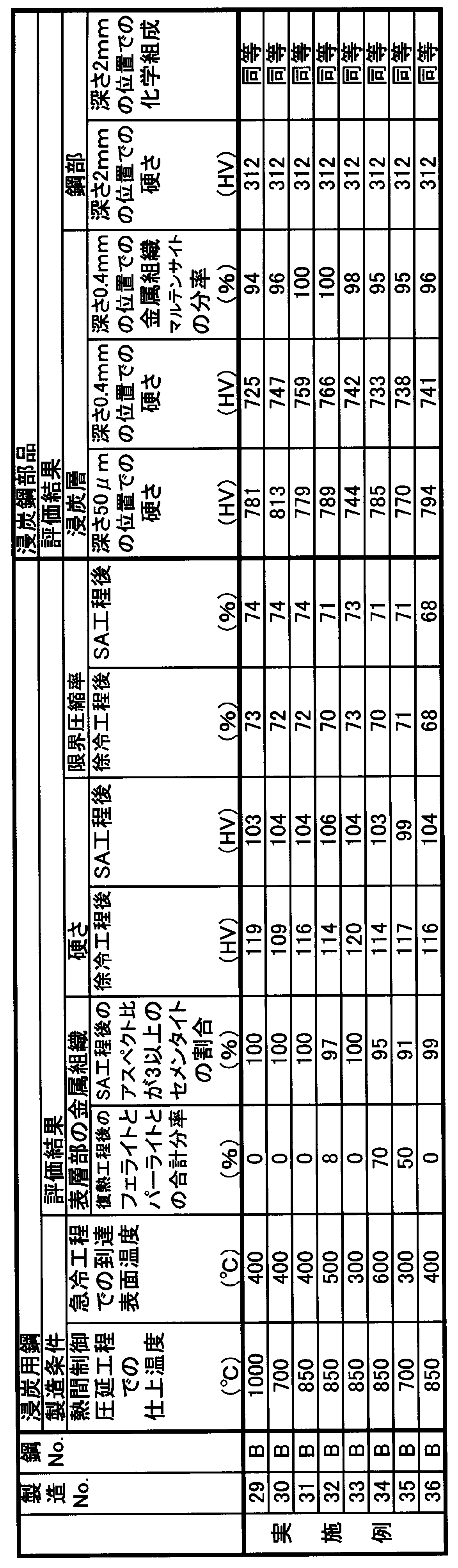
Claims (13)
- 化学成分が、質量%で、
C:0.07%~0.13%、
Si:0.0001%~0.50%、
Mn:0.0001%~0.80%、
S:0.0001%~0.100%、
Cr:1.30%超~5.00%、
B:0.0005%~0.0100%、
Al:0.070%~0.200%、
N:0.0030%~0.0100%
を含有し、
Ti:0.020%以下、
P:0.050%以下、
O:0.0030%以下
に制限し、
残部がFe及び不可避的不純物からなり、
前記化学成分中の各元素の質量%で示した含有量が、
硬さ指標として下記の式1、
焼入れ性指標として下記の式2、及び、
AlN析出量指標として下記の式3、
を同時に満足する
ことを特徴とする浸炭用鋼。
0.10<C+0.194×Si+0.065×Mn+0.012×Cr+0.078×Al<0.235・・・(式1)
7.5<(0.7×Si+1)×(5.1×Mn+1)×(2.16×Cr+1)<44・・・(式2)
0.0003<Al×(N-Ti×(14/48))<0.0011・・・(式3) - 前記化学成分が、更に、質量%で
Nb:0.002%~0.100%、
V:0.002%~0.20%、
Mo:0.005%~0.50%、
Ni:0.005%~1.00%、
Cu:0.005%~0.50%、
Ca:0.0002%~0.0030%、
Mg:0.0002%~0.0030%、
Te:0.0002%~0.0030%、
Zr:0.0002%~0.0050%、
Rare Earth Metal:0.0002%~0.0050%、
Sb:0.002%~0.050%
のうちの少なくとも1つを含有し、
前記硬さ指標が前記式1に代わって下記の式4に、前記焼入れ性指標が前記式2に代わって下記の式5に、定義される
ことを特徴とする請求項1に記載の浸炭用鋼。
0.10<C+0.194×Si+0.065×Mn+0.012×Cr+0.033×Mo+0.067×Ni+0.097×Cu+0.078×Al<0.235・・・(式4)
7.5<(0.7×Si+1)×(5.1×Mn+1)×(2.16×Cr+1)×(3×Mo+1)×(0.3633×Ni+1)<44・・・(式5) - 請求項1又は2に記載の浸炭用鋼であって、
金属組織が、面積%で、フェライトとパーライトとを、合計で、85%以上100%以下含む
ことを特徴とする浸炭用鋼。 - 請求項3に記載の浸炭用鋼であって、
前記金属組織が、面積%で、前記フェライトと球状化セメンタイトとを、合計で、85%以上100%以下含む
ことを特徴とする浸炭用鋼。 - 請求項1又は2に記載の浸炭用鋼であって、
形状が、長手方向と直交する切断面が円形となる棒状又は線状であり、
周面から前記切断面の中心までの距離を単位mmでrとすると、周面からr×0.01までの領域である表層部の金属組織が、面積%で、フェライトとパーライトとを、合計で、10%以下に制限し、
残部がマルテンサイト、ベイナイト、焼戻しマルテンサイト、焼戻しベイナイト、及び、セメンタイトのうちの少なくとも1つを含む
ことを特徴とする浸炭用鋼。 - 請求項5に記載の浸炭用鋼であって、
前記表層部の前記金属組織に含まれるセメンタイトのうち、90%以上100%以下が、アスペクト比3以下のセメンタイトである
ことを特徴とする浸炭用鋼。 - 請求項1又は2に記載の浸炭用鋼の製造方法であって:
鋳片を得る鋳造工程と;
前記鋳片を、熱間塑性加工して熱間加工鋼材を得る熱間加工工程と;
前記熱間加工工程後に、前記熱間加工鋼材の表面温度が800℃~500℃となる温度範囲を0℃/秒超1℃/秒以下の冷却速度で徐冷する徐冷工程と;を有する
ことを特徴とする浸炭用鋼の製造方法。 - 前記徐冷工程後の前記熱間加工鋼材に、更に、球状化熱処理を施す球状化熱処理工程を有する
ことを特徴とする請求項7に記載の浸炭用鋼の製造方法。 - 請求項1又は2に記載の浸炭用鋼の製造方法であって:
鋳片を得る鋳造工程と;
前記鋳片を、最終仕上圧延の出口側で表面温度が700℃~1000℃となる条件に制御して熱間圧延を行って熱間制御圧延鋼材を得る熱間制御圧延工程と;
前記熱間制御圧延工程後に、前記熱間制御圧延鋼材の表面温度が0℃超500℃以下となるように急冷する急冷工程と;
前記急冷工程後の前記熱間制御圧延鋼材を少なくとも1回以上復熱させる復熱工程と;を有する
ことを特徴とする浸炭用鋼の製造方法。 - 前記復熱工程後の前記熱間制御圧延鋼材に、更に、球状化熱処理を施す球状化熱処理工程を有する
ことを特徴とする請求項9に記載の浸炭用鋼の製造方法。 - 鋼部と、前記鋼部の外面に生成した厚さ0.4mm超2mm未満の浸炭層とを備える浸炭鋼部品であって:
前記浸炭層において、
表面から深さ50μmの位置でのビッカース硬さがHV650以上HV1000以下であり、前記表面から深さ0.4mmの位置でのビッカース硬さがHV550以上HV900以下であり、かつ、前記表面から深さ0.4mmの位置での金属組織が、面積%で、マルテンサイトを90%以上100%以下含み;
前記表面から深さ2mmの位置の前記鋼部について、
請求項1又は2に記載の前記化学成分からなり、かつ、ビッカース硬さがHV250以上HV500以下である
ことを特徴とする浸炭鋼部品。 - 請求項11に記載の浸炭鋼部品の製造方法であって:
前記浸炭用鋼に、冷間塑性加工を施して形状を付与する冷間加工工程と;
前記冷間加工工程後の前記浸炭用鋼に、浸炭処理、又は浸炭窒化処理を施す浸炭工程と;
前記浸炭工程後に、焼入れ処理、又は焼入れ・焼戻し処理を施す仕上熱処理工程と;を有する
ことを特徴とする浸炭鋼部品の製造方法。 - 請求項12に記載の浸炭鋼部品の製造方法であって、
前記冷間加工工程後で前記浸炭工程前に、更に、切削加工を施して形状を付与する切削工程を有する
ことを特徴とする浸炭鋼部品の製造方法。
Priority Applications (5)
| Application Number | Priority Date | Filing Date | Title |
|---|---|---|---|
| KR1020137007148A KR101488120B1 (ko) | 2011-02-10 | 2012-02-08 | 침탄용 강, 침탄강 부품 및 그 제조 방법 |
| US13/818,056 US9796158B2 (en) | 2011-02-10 | 2012-02-08 | Steel for carburizing, carburized steel component, and method of producing the same |
| CN201280003024.1A CN103119189B (zh) | 2011-02-10 | 2012-02-08 | 渗碳用钢、渗碳钢部件及其制造方法 |
| JP2012529017A JP5135562B2 (ja) | 2011-02-10 | 2012-02-08 | 浸炭用鋼、浸炭鋼部品、及び、その製造方法 |
| US15/622,712 US10391742B2 (en) | 2011-02-10 | 2017-06-14 | Steel for carburizing, carburized steel component, and method of producing the same |
Applications Claiming Priority (2)
| Application Number | Priority Date | Filing Date | Title |
|---|---|---|---|
| JP2011027279 | 2011-02-10 | ||
| JP2011-027279 | 2011-02-10 |
Related Child Applications (2)
| Application Number | Title | Priority Date | Filing Date |
|---|---|---|---|
| US13/818,056 A-371-Of-International US9796158B2 (en) | 2011-02-10 | 2012-02-08 | Steel for carburizing, carburized steel component, and method of producing the same |
| US15/622,712 Division US10391742B2 (en) | 2011-02-10 | 2017-06-14 | Steel for carburizing, carburized steel component, and method of producing the same |
Publications (1)
| Publication Number | Publication Date |
|---|---|
| WO2012108461A1 true WO2012108461A1 (ja) | 2012-08-16 |
Family
ID=46638674
Family Applications (1)
| Application Number | Title | Priority Date | Filing Date |
|---|---|---|---|
| PCT/JP2012/052854 Ceased WO2012108461A1 (ja) | 2011-02-10 | 2012-02-08 | 浸炭用鋼、浸炭鋼部品、及び、その製造方法 |
Country Status (5)
| Country | Link |
|---|---|
| US (2) | US9796158B2 (ja) |
| JP (1) | JP5135562B2 (ja) |
| KR (1) | KR101488120B1 (ja) |
| CN (1) | CN103119189B (ja) |
| WO (1) | WO2012108461A1 (ja) |
Cited By (12)
| Publication number | Priority date | Publication date | Assignee | Title |
|---|---|---|---|---|
| CN102978514A (zh) * | 2012-11-07 | 2013-03-20 | 韶关市新世科壳型铸造有限公司 | 一种提高ZG40Cr氮化层厚度的方法 |
| US20140299234A1 (en) * | 2013-04-08 | 2014-10-09 | Honda Motor Co., Ltd. | Carburized part, method for manufacturing thereof, and steel for carburized part |
| WO2016148037A1 (ja) * | 2015-03-13 | 2016-09-22 | 株式会社神戸製鋼所 | 冷間加工性と浸炭熱処理後の靱性に優れる浸炭用鋼板 |
| WO2017090738A1 (ja) * | 2015-11-27 | 2017-06-01 | 新日鐵住金株式会社 | 鋼、浸炭鋼部品、及び浸炭鋼部品の製造方法 |
| WO2017090731A1 (ja) * | 2015-11-27 | 2017-06-01 | 新日鐵住金株式会社 | 鋼、浸炭鋼部品、及び浸炭鋼部品の製造方法 |
| JP2018035420A (ja) * | 2016-09-01 | 2018-03-08 | 新日鐵住金株式会社 | 浸炭用鋼、浸炭鋼部品及び浸炭鋼部品の製造方法 |
| JP2018035419A (ja) * | 2016-09-01 | 2018-03-08 | 新日鐵住金株式会社 | 浸炭用鋼、浸炭鋼部品及び浸炭鋼部品の製造方法 |
| JP2019011510A (ja) * | 2018-08-20 | 2019-01-24 | 株式会社神戸製鋼所 | 冷間加工性と浸炭熱処理後の靱性に優れる浸炭用鋼板 |
| CN110284071A (zh) * | 2019-08-02 | 2019-09-27 | 宜兴市佳信数控科技有限公司 | 一种回转窑用超大齿轮及其制备方法 |
| JP2020105603A (ja) * | 2018-12-28 | 2020-07-09 | 日本製鉄株式会社 | 浸炭鋼部品用鋼材 |
| JP2020105602A (ja) * | 2018-12-28 | 2020-07-09 | 日本製鉄株式会社 | 浸炭鋼部品用鋼材 |
| US11111568B2 (en) | 2016-09-30 | 2021-09-07 | Nippon Steel Corporation | Steel for cold forging and manufacturing method thereof |
Families Citing this family (18)
| Publication number | Priority date | Publication date | Assignee | Title |
|---|---|---|---|---|
| JP3413609B2 (ja) | 1993-06-10 | 2003-06-03 | エヌイーシートーキン株式会社 | Fe−Cr−Co系磁石合金およびその製造方法 |
| JP5432105B2 (ja) * | 2010-09-28 | 2014-03-05 | 株式会社神戸製鋼所 | 肌焼鋼およびその製造方法 |
| JP6260117B2 (ja) | 2013-06-05 | 2018-01-17 | 大同特殊鋼株式会社 | 浸炭部品とその製造方法 |
| CN103710640B (zh) * | 2013-12-30 | 2016-05-25 | 钢铁研究总院 | 一种经济节约型调质处理690MPa级高强高韧钢板 |
| CN105899705B (zh) * | 2014-03-20 | 2017-12-08 | 新日铁住金株式会社 | 良加工性钢线材及其制造方法 |
| JP2016020537A (ja) * | 2014-06-16 | 2016-02-04 | 株式会社神戸製鋼所 | 冷間加工用機械構造用鋼及びその製造方法 |
| KR101657848B1 (ko) * | 2014-12-26 | 2016-09-20 | 주식회사 포스코 | 단조성이 우수한 연자성 강재, 연자성 강 부품 및 그들의 제조방법 |
| CN105606539B (zh) * | 2016-01-04 | 2018-09-18 | 河北钢铁股份有限公司邯郸分公司 | Dp780双相钢马氏体、铁素体、贝氏体含量检测方法 |
| FR3054017B1 (fr) * | 2016-07-13 | 2018-07-13 | Societe Nouvelle Stim | Procede de traitement a l'interieur de tuyauteries types acier de cementation destinees au transport de pulverulents et autres solides abrasifs aux fins de retarder le percement de l'enveloppe |
| TWI663266B (zh) | 2017-02-28 | 2019-06-21 | 日商杰富意鋼鐵股份有限公司 | 切削加工用線材 |
| BR112019008773A2 (pt) * | 2018-10-02 | 2021-04-13 | Nippon Steel Corporation | Chapa de aço para carburação, e método de produção da chapa de aço para carburação |
| CN109402335A (zh) * | 2019-01-07 | 2019-03-01 | 上海钰灏新材料科技有限公司 | 一种渗钛层模具钢及其制备方法 |
| CN113272451B (zh) * | 2019-01-11 | 2022-07-05 | 日本制铁株式会社 | 钢材 |
| CN110952022A (zh) * | 2019-10-31 | 2020-04-03 | 宝钢特钢长材有限公司 | 一种窄淬透性高温细晶粒MnCr齿轮钢及其制备方法 |
| JP7478685B2 (ja) * | 2020-02-19 | 2024-05-07 | クエステック イノベーションズ リミテッド ライアビリティ カンパニー | 析出強化された浸炭可能及び窒化可能な合金鋼 |
| JP7257351B2 (ja) * | 2020-03-17 | 2023-04-13 | 愛知製鋼株式会社 | 真空浸炭用粗形材及びその製造方法 |
| US11624106B2 (en) * | 2020-03-18 | 2023-04-11 | Caterpillar Inc. | Carburized steel component and carburization process |
| CN120818747B (zh) * | 2025-09-17 | 2025-11-18 | 鞍钢股份有限公司 | 一种350MPa级低屈强比抗冲击零部件用钢、制造方法及零部件渗碳处理方法 |
Citations (5)
| Publication number | Priority date | Publication date | Assignee | Title |
|---|---|---|---|---|
| JP2002155344A (ja) * | 2000-09-11 | 2002-05-31 | Koji Onoe | 高強度ねじ用鋼および高強度ねじ |
| JP2003231917A (ja) * | 2002-02-07 | 2003-08-19 | Aichi Steel Works Ltd | 冷鍛用肌焼鋼の製造方法及びその方法により製造された冷鍛用肌焼鋼 |
| JP2008291298A (ja) * | 2007-05-23 | 2008-12-04 | Daido Steel Co Ltd | 浸炭用鋼、浸炭部品及び浸炭部品の製造方法 |
| JP2009030160A (ja) * | 2007-06-28 | 2009-02-12 | Kobe Steel Ltd | 被削性に優れた機械構造用鋼およびその製造方法 |
| JP2009068064A (ja) * | 2007-09-12 | 2009-04-02 | Sanyo Special Steel Co Ltd | 面圧疲労強度と衝撃強度及び曲げ疲労強度に優れたはだ焼鋼 |
Family Cites Families (11)
| Publication number | Priority date | Publication date | Assignee | Title |
|---|---|---|---|---|
| JP3764586B2 (ja) | 1998-05-22 | 2006-04-12 | 新日本製鐵株式会社 | 冷間加工性と低浸炭歪み特性に優れた肌焼鋼の製造方法 |
| JP4435954B2 (ja) * | 1999-12-24 | 2010-03-24 | 新日本製鐵株式会社 | 冷間鍛造用棒線材とその製造方法 |
| JP3764627B2 (ja) | 2000-04-18 | 2006-04-12 | 新日本製鐵株式会社 | 浸炭時に異常組織を生成しない冷間鍛造用肌焼ボロン鋼とその製造方法 |
| JP4847681B2 (ja) | 2004-02-06 | 2011-12-28 | 株式会社神戸製鋼所 | Ti含有肌焼き鋼 |
| JP2007289979A (ja) | 2006-04-23 | 2007-11-08 | Sanyo Special Steel Co Ltd | Ti添加はだ焼鋼からなる鋳鋼片または鋼塊の製造方法およびその鋳鋼片または鋼塊並びにその鋳鋼片または鋼塊からなるはだ焼鋼鋼材 |
| JP5200634B2 (ja) | 2007-04-11 | 2013-06-05 | 新日鐵住金株式会社 | 鍛造及び浸炭用熱間圧延棒鋼 |
| JP2008291128A (ja) | 2007-05-25 | 2008-12-04 | Hiroyoshi Kubota | エマルジョン燃料 |
| CN101397631A (zh) | 2007-09-28 | 2009-04-01 | 新日本制铁株式会社 | 冷锻性和低渗碳变形特性优良的表面渗碳钢 |
| KR101363845B1 (ko) | 2009-01-16 | 2014-02-17 | 신닛테츠스미킨 카부시키카이샤 | 표면 경화강, 침탄 부품 및 표면 경화강의 제조 방법 |
| JP5262740B2 (ja) | 2009-01-16 | 2013-08-14 | 新日鐵住金株式会社 | 浸炭時の粗大粒防止特性と疲労特性に優れた肌焼鋼とその製造方法 |
| TWI494445B (zh) | 2009-03-30 | 2015-08-01 | Nippon Steel & Sumitomo Metal Corp | 滲碳鋼零件(一) |
-
2012
- 2012-02-08 JP JP2012529017A patent/JP5135562B2/ja active Active
- 2012-02-08 US US13/818,056 patent/US9796158B2/en not_active Expired - Fee Related
- 2012-02-08 CN CN201280003024.1A patent/CN103119189B/zh not_active Expired - Fee Related
- 2012-02-08 WO PCT/JP2012/052854 patent/WO2012108461A1/ja not_active Ceased
- 2012-02-08 KR KR1020137007148A patent/KR101488120B1/ko not_active Expired - Fee Related
-
2017
- 2017-06-14 US US15/622,712 patent/US10391742B2/en not_active Expired - Fee Related
Patent Citations (5)
| Publication number | Priority date | Publication date | Assignee | Title |
|---|---|---|---|---|
| JP2002155344A (ja) * | 2000-09-11 | 2002-05-31 | Koji Onoe | 高強度ねじ用鋼および高強度ねじ |
| JP2003231917A (ja) * | 2002-02-07 | 2003-08-19 | Aichi Steel Works Ltd | 冷鍛用肌焼鋼の製造方法及びその方法により製造された冷鍛用肌焼鋼 |
| JP2008291298A (ja) * | 2007-05-23 | 2008-12-04 | Daido Steel Co Ltd | 浸炭用鋼、浸炭部品及び浸炭部品の製造方法 |
| JP2009030160A (ja) * | 2007-06-28 | 2009-02-12 | Kobe Steel Ltd | 被削性に優れた機械構造用鋼およびその製造方法 |
| JP2009068064A (ja) * | 2007-09-12 | 2009-04-02 | Sanyo Special Steel Co Ltd | 面圧疲労強度と衝撃強度及び曲げ疲労強度に優れたはだ焼鋼 |
Cited By (21)
| Publication number | Priority date | Publication date | Assignee | Title |
|---|---|---|---|---|
| CN102978514A (zh) * | 2012-11-07 | 2013-03-20 | 韶关市新世科壳型铸造有限公司 | 一种提高ZG40Cr氮化层厚度的方法 |
| US9771643B2 (en) * | 2013-04-08 | 2017-09-26 | Honda Motor Co., Ltd. | Carburized part, method for manufacturing thereof, and steel for carburized part |
| US20140299234A1 (en) * | 2013-04-08 | 2014-10-09 | Honda Motor Co., Ltd. | Carburized part, method for manufacturing thereof, and steel for carburized part |
| CN104099518A (zh) * | 2013-04-08 | 2014-10-15 | 大同特殊钢株式会社 | 渗碳部件、其制造方法、和渗碳部件用钢 |
| CN104099518B (zh) * | 2013-04-08 | 2018-04-17 | 大同特殊钢株式会社 | 渗碳部件、其制造方法、和渗碳部件用钢 |
| WO2016148037A1 (ja) * | 2015-03-13 | 2016-09-22 | 株式会社神戸製鋼所 | 冷間加工性と浸炭熱処理後の靱性に優れる浸炭用鋼板 |
| JP2016169433A (ja) * | 2015-03-13 | 2016-09-23 | 株式会社神戸製鋼所 | 冷間加工性と浸炭熱処理後の靱性に優れる浸炭用鋼板 |
| WO2017090738A1 (ja) * | 2015-11-27 | 2017-06-01 | 新日鐵住金株式会社 | 鋼、浸炭鋼部品、及び浸炭鋼部品の製造方法 |
| WO2017090731A1 (ja) * | 2015-11-27 | 2017-06-01 | 新日鐵住金株式会社 | 鋼、浸炭鋼部品、及び浸炭鋼部品の製造方法 |
| JPWO2017090738A1 (ja) * | 2015-11-27 | 2018-09-13 | 新日鐵住金株式会社 | 鋼、浸炭鋼部品、及び浸炭鋼部品の製造方法 |
| JPWO2017090731A1 (ja) * | 2015-11-27 | 2018-10-04 | 新日鐵住金株式会社 | 鋼、浸炭鋼部品、及び浸炭鋼部品の製造方法 |
| US10597765B2 (en) | 2015-11-27 | 2020-03-24 | Nippon Steel Corporation | Steel, carburized steel component, and method for manufacturing carburized steel component |
| JP2018035420A (ja) * | 2016-09-01 | 2018-03-08 | 新日鐵住金株式会社 | 浸炭用鋼、浸炭鋼部品及び浸炭鋼部品の製造方法 |
| JP2018035419A (ja) * | 2016-09-01 | 2018-03-08 | 新日鐵住金株式会社 | 浸炭用鋼、浸炭鋼部品及び浸炭鋼部品の製造方法 |
| US11111568B2 (en) | 2016-09-30 | 2021-09-07 | Nippon Steel Corporation | Steel for cold forging and manufacturing method thereof |
| JP2019011510A (ja) * | 2018-08-20 | 2019-01-24 | 株式会社神戸製鋼所 | 冷間加工性と浸炭熱処理後の靱性に優れる浸炭用鋼板 |
| JP2020105602A (ja) * | 2018-12-28 | 2020-07-09 | 日本製鉄株式会社 | 浸炭鋼部品用鋼材 |
| JP2020105603A (ja) * | 2018-12-28 | 2020-07-09 | 日本製鉄株式会社 | 浸炭鋼部品用鋼材 |
| JP7151474B2 (ja) | 2018-12-28 | 2022-10-12 | 日本製鉄株式会社 | 浸炭鋼部品用鋼材 |
| JP7156021B2 (ja) | 2018-12-28 | 2022-10-19 | 日本製鉄株式会社 | 浸炭鋼部品用鋼材 |
| CN110284071A (zh) * | 2019-08-02 | 2019-09-27 | 宜兴市佳信数控科技有限公司 | 一种回转窑用超大齿轮及其制备方法 |
Also Published As
| Publication number | Publication date |
|---|---|
| KR101488120B1 (ko) | 2015-01-29 |
| JPWO2012108461A1 (ja) | 2014-07-03 |
| US20130146181A1 (en) | 2013-06-13 |
| US10391742B2 (en) | 2019-08-27 |
| JP5135562B2 (ja) | 2013-02-06 |
| KR20130048259A (ko) | 2013-05-09 |
| CN103119189B (zh) | 2015-04-22 |
| CN103119189A (zh) | 2013-05-22 |
| US20170282501A1 (en) | 2017-10-05 |
| US9796158B2 (en) | 2017-10-24 |
Similar Documents
| Publication | Publication Date | Title |
|---|---|---|
| JP5135562B2 (ja) | 浸炭用鋼、浸炭鋼部品、及び、その製造方法 | |
| JP5135563B2 (ja) | 浸炭用鋼、浸炭鋼部品、及び、その製造方法 | |
| JP6226085B2 (ja) | 冷間鍛造部品用圧延棒鋼または圧延線材 | |
| JP6468366B2 (ja) | 鋼、浸炭鋼部品、及び浸炭鋼部品の製造方法 | |
| JPWO2014171472A1 (ja) | 肌焼用鋼材と肌焼鋼部品 | |
| JP7168003B2 (ja) | 鋼材 | |
| JP6468365B2 (ja) | 鋼、浸炭鋼部品、及び浸炭鋼部品の製造方法 | |
| JP6628014B1 (ja) | 浸炭処理が行われる部品用の鋼材 | |
| US11952650B2 (en) | Steel wire | |
| JP2018035419A (ja) | 浸炭用鋼、浸炭鋼部品及び浸炭鋼部品の製造方法 | |
| JP2021088751A (ja) | 転動部品及びその製造方法 | |
| US12006994B2 (en) | Valve spring | |
| JP2020105603A (ja) | 浸炭鋼部品用鋼材 | |
| JP2018035418A (ja) | 浸炭用鋼、浸炭鋼部品及び浸炭鋼部品の製造方法 |
Legal Events
| Date | Code | Title | Description |
|---|---|---|---|
| WWE | Wipo information: entry into national phase |
Ref document number: 201280003024.1 Country of ref document: CN |
|
| WWE | Wipo information: entry into national phase |
Ref document number: 2012529017 Country of ref document: JP |
|
| 121 | Ep: the epo has been informed by wipo that ep was designated in this application |
Ref document number: 12744424 Country of ref document: EP Kind code of ref document: A1 |
|
| WWE | Wipo information: entry into national phase |
Ref document number: 13818056 Country of ref document: US |
|
| ENP | Entry into the national phase |
Ref document number: 20137007148 Country of ref document: KR Kind code of ref document: A |
|
| NENP | Non-entry into the national phase |
Ref country code: DE |
|
| 122 | Ep: pct application non-entry in european phase |
Ref document number: 12744424 Country of ref document: EP Kind code of ref document: A1 |