WO2012107977A1 - 舶用発電システム - Google Patents
舶用発電システム Download PDFInfo
- Publication number
- WO2012107977A1 WO2012107977A1 PCT/JP2011/006283 JP2011006283W WO2012107977A1 WO 2012107977 A1 WO2012107977 A1 WO 2012107977A1 JP 2011006283 W JP2011006283 W JP 2011006283W WO 2012107977 A1 WO2012107977 A1 WO 2012107977A1
- Authority
- WO
- WIPO (PCT)
- Prior art keywords
- power
- generator
- waste heat
- steam
- generated
- Prior art date
- Legal status (The legal status is an assumption and is not a legal conclusion. Google has not performed a legal analysis and makes no representation as to the accuracy of the status listed.)
- Ceased
Links
Images
Classifications
-
- B—PERFORMING OPERATIONS; TRANSPORTING
- B63—SHIPS OR OTHER WATERBORNE VESSELS; RELATED EQUIPMENT
- B63J—AUXILIARIES ON VESSELS
- B63J3/00—Driving of auxiliaries
-
- F—MECHANICAL ENGINEERING; LIGHTING; HEATING; WEAPONS; BLASTING
- F01—MACHINES OR ENGINES IN GENERAL; ENGINE PLANTS IN GENERAL; STEAM ENGINES
- F01K—STEAM ENGINE PLANTS; STEAM ACCUMULATORS; ENGINE PLANTS NOT OTHERWISE PROVIDED FOR; ENGINES USING SPECIAL WORKING FLUIDS OR CYCLES
- F01K23/00—Plants characterised by more than one engine delivering power external to the plant, the engines being driven by different fluids
- F01K23/02—Plants characterised by more than one engine delivering power external to the plant, the engines being driven by different fluids the engine cycles being thermally coupled
- F01K23/06—Plants characterised by more than one engine delivering power external to the plant, the engines being driven by different fluids the engine cycles being thermally coupled combustion heat from one cycle heating the fluid in another cycle
- F01K23/10—Plants characterised by more than one engine delivering power external to the plant, the engines being driven by different fluids the engine cycles being thermally coupled combustion heat from one cycle heating the fluid in another cycle with exhaust fluid of one cycle heating the fluid in another cycle
-
- F—MECHANICAL ENGINEERING; LIGHTING; HEATING; WEAPONS; BLASTING
- F01—MACHINES OR ENGINES IN GENERAL; ENGINE PLANTS IN GENERAL; STEAM ENGINES
- F01D—NON-POSITIVE DISPLACEMENT MACHINES OR ENGINES, e.g. STEAM TURBINES
- F01D15/00—Adaptations of machines or engines for special use; Combinations of engines with devices driven thereby
- F01D15/02—Adaptations for driving vehicles, e.g. locomotives
- F01D15/04—Adaptations for driving vehicles, e.g. locomotives the vehicles being waterborne vessels
-
- F—MECHANICAL ENGINEERING; LIGHTING; HEATING; WEAPONS; BLASTING
- F01—MACHINES OR ENGINES IN GENERAL; ENGINE PLANTS IN GENERAL; STEAM ENGINES
- F01K—STEAM ENGINE PLANTS; STEAM ACCUMULATORS; ENGINE PLANTS NOT OTHERWISE PROVIDED FOR; ENGINES USING SPECIAL WORKING FLUIDS OR CYCLES
- F01K23/00—Plants characterised by more than one engine delivering power external to the plant, the engines being driven by different fluids
- F01K23/02—Plants characterised by more than one engine delivering power external to the plant, the engines being driven by different fluids the engine cycles being thermally coupled
- F01K23/06—Plants characterised by more than one engine delivering power external to the plant, the engines being driven by different fluids the engine cycles being thermally coupled combustion heat from one cycle heating the fluid in another cycle
-
- F—MECHANICAL ENGINEERING; LIGHTING; HEATING; WEAPONS; BLASTING
- F01—MACHINES OR ENGINES IN GENERAL; ENGINE PLANTS IN GENERAL; STEAM ENGINES
- F01K—STEAM ENGINE PLANTS; STEAM ACCUMULATORS; ENGINE PLANTS NOT OTHERWISE PROVIDED FOR; ENGINES USING SPECIAL WORKING FLUIDS OR CYCLES
- F01K23/00—Plants characterised by more than one engine delivering power external to the plant, the engines being driven by different fluids
- F01K23/02—Plants characterised by more than one engine delivering power external to the plant, the engines being driven by different fluids the engine cycles being thermally coupled
- F01K23/06—Plants characterised by more than one engine delivering power external to the plant, the engines being driven by different fluids the engine cycles being thermally coupled combustion heat from one cycle heating the fluid in another cycle
- F01K23/065—Plants characterised by more than one engine delivering power external to the plant, the engines being driven by different fluids the engine cycles being thermally coupled combustion heat from one cycle heating the fluid in another cycle the combustion taking place in an internal combustion piston engine, e.g. a diesel engine
-
- F—MECHANICAL ENGINEERING; LIGHTING; HEATING; WEAPONS; BLASTING
- F02—COMBUSTION ENGINES; HOT-GAS OR COMBUSTION-PRODUCT ENGINE PLANTS
- F02G—HOT GAS OR COMBUSTION-PRODUCT POSITIVE-DISPLACEMENT ENGINE PLANTS; USE OF WASTE HEAT OF COMBUSTION ENGINES; NOT OTHERWISE PROVIDED FOR
- F02G5/00—Profiting from waste heat of combustion engines, not otherwise provided for
-
- F—MECHANICAL ENGINEERING; LIGHTING; HEATING; WEAPONS; BLASTING
- F22—STEAM GENERATION
- F22B—METHODS OF STEAM GENERATION; STEAM BOILERS
- F22B1/00—Methods of steam generation characterised by form of heating method
- F22B1/02—Methods of steam generation characterised by form of heating method by exploitation of the heat content of hot heat carriers
- F22B1/18—Methods of steam generation characterised by form of heating method by exploitation of the heat content of hot heat carriers the heat carrier being a hot gas, e.g. waste gas such as exhaust gas of internal-combustion engines
- F22B1/1807—Methods of steam generation characterised by form of heating method by exploitation of the heat content of hot heat carriers the heat carrier being a hot gas, e.g. waste gas such as exhaust gas of internal-combustion engines using the exhaust gases of combustion engines
-
- Y—GENERAL TAGGING OF NEW TECHNOLOGICAL DEVELOPMENTS; GENERAL TAGGING OF CROSS-SECTIONAL TECHNOLOGIES SPANNING OVER SEVERAL SECTIONS OF THE IPC; TECHNICAL SUBJECTS COVERED BY FORMER USPC CROSS-REFERENCE ART COLLECTIONS [XRACs] AND DIGESTS
- Y02—TECHNOLOGIES OR APPLICATIONS FOR MITIGATION OR ADAPTATION AGAINST CLIMATE CHANGE
- Y02E—REDUCTION OF GREENHOUSE GAS [GHG] EMISSIONS, RELATED TO ENERGY GENERATION, TRANSMISSION OR DISTRIBUTION
- Y02E20/00—Combustion technologies with mitigation potential
- Y02E20/30—Technologies for a more efficient combustion or heat usage
Definitions
- the present invention relates to a marine power generation system that drives a steam turbine with steam generated from waste heat of a main engine and generates electric power based on the output of the steam turbine.
- JP 2010-116847 A JP-A-5-65804 JP-A-8-93410
- the main engine when the main engine is operating at a low load, the amount of exhaust gas and the amount of waste heat around the main engine are reduced, so that the amount of steam flowing into the steam turbine is reduced.
- soot contained in the exhaust gas may adhere to the exhaust gas economizer, and in order to maintain the heat recovery efficiency of the waste heat recovery system, the work to remove the soot (soot blow) is appropriate. It is necessary to perform every period. Even when this soot blow is performed using the steam generated in the waste heat recovery system, the amount of steam flowing into the steam turbine is reduced. When the amount of steam decreases in this way, the output of the steam turbine decreases, so there is a possibility that the power demand of the ship cannot be covered by the amount of power generated by the generator.
- the power demand on board may be temporarily larger than the power that is used continuously.
- the power demand in the ship becomes a value obtained by adding the power necessary for the start to the continuous power.
- the amount of steam supplied to the steam turbine is increased by operating the auxiliary boiler under circumstances where the amount of steam is low or when the power demand on the ship is temporarily larger than the continuous power. This is done by increasing the amount of power generated by the generator or by operating another generator such as a diesel generator.
- a diesel generator In general, the operation of the auxiliary boiler and the diesel generator requires fossil fuel, which increases running costs and makes it difficult to achieve high energy savings.
- the power generation amount of the generator is temporarily converted to continuous power when the main engine is under low load. It is conceivable to design the system so that the required power is added. However, in this case, it is necessary to ensure that the steam turbine generates a large output even when the main engine has a low load, resulting in an increase in the size of the configuration of the waste heat recovery system. Then, it becomes difficult to arrange a ship power generation system in a limited ship space. In addition, when the main engine has a high load, the power generation amount of the generator exceeds the power demand in the ship, and surplus power that cannot be effectively used is generated.
- the present invention can provide a marine power generation system that can cover the fluctuating power demand on board while minimizing the use of fossil fuels, and can effectively utilize surplus power when it can be generated from the generator.
- the purpose is to provide a system.
- a marine power generation system includes a waste heat recovery system that recovers waste heat of a main engine to generate steam, a steam turbine that is driven by steam generated by the waste heat recovery system, and an output of the steam turbine And a storage battery electrically connected to the generator, and the generator can generate electric power due to waste heat when the load of the main engine is in a high load range.
- a waste heat recovery system that recovers waste heat of a main engine to generate steam
- a steam turbine that is driven by steam generated by the waste heat recovery system
- an output of the steam turbine
- a storage battery electrically connected to the generator, and the generator can generate electric power due to waste heat when the load of the main engine is in a high load range. Is configured to be larger than the continuous power required continuously in the ship, and smaller than the total demand power added to the continuous power temporarily and additionally, and the storage battery is disposed of.
- the storage battery can be charged with surplus power generated by the generator when the power that can be generated by the generator due to waste heat can sufficiently cover the power demand in the ship.
- the surplus power can be used effectively.
- the storage battery can be discharged to assist the drive of the generator. Thereby, the electric power generation amount of a generator can be raised and the opportunity to operate an auxiliary boiler or a diesel generator can be reduced.
- the power that can be generated by the generator due to waste heat when the load on the main engine is in the high load range is set to be larger than the continuous power and smaller than the total demand power. For this reason, the opportunity to charge during the normal navigation of the main engine and the opportunity to discharge appear without being biased, and the storage battery can be charged and discharged in a well-balanced manner.
- Control means for controlling charging / discharging of the storage battery the control means by the generator when a predetermined charging condition in which the power that can be generated by the generator due to waste heat exceeds the power demand in the ship is satisfied.
- the storage battery is charged with the generated surplus power, and the generator is discharged by discharging the storage battery when a predetermined discharge condition is established where the power that can be generated by the generator due to waste heat is less than the power demand in the ship. It may be configured to implement control for assisting the driving of.
- the charging operation and discharging operation of the storage battery can be appropriately switched depending on the situation.
- An auxiliary machine start detecting means for detecting start of an auxiliary machine in the ship is further provided, and the charging condition includes a condition that the start of the auxiliary machine is not detected by the auxiliary machine start detecting means, and the discharge condition is
- the auxiliary machine start detection means may include a condition that the start of the auxiliary machine is detected.
- the storage battery is discharged correspondingly to assist the driving of the generator. It is possible to reduce the opportunity to operate the auxiliary boiler and the diesel generator.
- Exhaust gas economizer that constitutes the waste heat recovery system and through which the exhaust gas of the main engine flows, a blower that injects steam generated by the waste heat recovery system into the exhaust gas economizer, and whether the blower is operating
- the charge condition includes a condition that a stop of the blower is detected by the blow detection means, and the discharge condition is determined by the blow detection means.
- a condition that the operation is detected may be included.
- the steam generated in the exhaust gas economizer cannot be used to drive all the steam generated by the waste heat recovery, the power that can be generated by the generator due to the waste heat is reduced. Even if it is a case, the drive of a generator can be assisted by discharging this storage battery in response to this. Therefore, the opportunity to operate the auxiliary boiler and the diesel generator can be reduced.
- a steam system that sends steam to the steam inlet of the steam turbine, and a governor valve that is provided with a variable lift amount in the steam system and adjusts the flow rate of the steam sent to the steam inlet by changing the lift amount
- a lift amount detecting means for detecting a lift amount of the governor valve
- the charging condition includes a condition that the lift amount detected by the lift amount detecting means is less than a first lift threshold value.
- the discharge condition may include a condition that the lift amount detected by the lift amount detection means is equal to or greater than a second lift threshold value that is greater than the first lift threshold value.
- a steam separator that constitutes the waste heat recovery system and accumulates the generated steam; and a pressure detector that detects an internal pressure of the steam separator, and the charging condition is detected by the pressure detector.
- the discharge condition includes a condition that the internal pressure detected by the pressure detection means is less than a second pressure threshold that is smaller than the first pressure threshold. May be included.
- the steam turbine can generate a large output when the steam pressure increases, and vice versa when the pressure decreases.
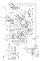
- FIG. 1 is a conceptual diagram showing the overall configuration of a marine power generation system according to an embodiment of the present invention.
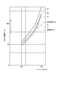
- FIG. 2 is a graph showing the relationship between the engine load and the power that can be generated by the generator due to waste heat.
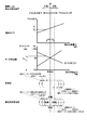
- Fig. 3 shows the correlation between the power that can be generated by the generator due to waste heat and the internal pressure of the high-pressure drum, the correlation between the power that can be generated by the waste heat and the lift amount of the governor valve, and the generation of the generator due to waste heat. It is a figure which shows the correlation diagram of possible electric power and a plan point, and the conceptual diagram of charging / discharging control collectively.
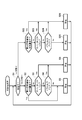
- FIG. 4 is a flowchart showing a procedure of charge / discharge control executed by the main controller.
- FIG. 1 is a conceptual diagram showing an overall configuration of a marine power generation system 100 according to an embodiment of the present invention.
- a marine power generation system 100 shown in FIG. 1 is mounted on a marine vessel equipped with a marine diesel engine 1 (hereinafter simply referred to as “engine”) as a main engine.
- engine a marine diesel engine 1 (hereinafter simply referred to as “engine”) as a main engine.
- the marine power generation system 100 includes a waste heat recovery system 2 that recovers waste heat from the periphery of the engine 1 to generate steam, a steam turbine 3 that is driven by the steam generated in the waste heat recovery system 2, and a steam turbine 3
- the generator 4 driven based on the output of the generator 4 and the storage battery 5 electrically connected to the generator 4 are provided.
- the waste heat recovery system 2 is mainly composed of an exhaust gas economizer 10, a condenser 21, a feed water system 22, a feed water heater 23, a high pressure drum (high pressure steam separator) 24, an intermediate pressure drum (medium pressure steam separator) 25, Low pressure drum (low pressure brackish water separator) 26, high pressure circulating water system 27, steam system 28, medium pressure circulating water system 29, medium pressure mixed water system 30, low pressure circulating water system 31, low pressure evaporator 32 and low pressure mixed gas system 33 It has.
- the waste heat recovered by the waste heat recovery system 2 includes heat of exhaust gas that is about to be discharged by the exhaust system of the engine 1, heat of cooling water of the engine 1, heat of supply air of the engine 1, and the like.
- the exhaust system of the engine 1 includes an exhaust pipe 1a for guiding exhaust gas to an exhaust outlet such as a chimney.
- the exhaust gas economizer 10 is interposed between the exhaust pipe 1a and the exhaust outlet and constitutes a part of the exhaust system.
- a bypass pipe 8 that bypasses the exhaust gas economizer 10 is connected to the exhaust pipe 1a.
- the inlet part of the exhaust gas economizer 10 and the inlet part of the bypass pipe 8 are opened and closed by a damper 9a and a damper 9b, respectively.
- the exhaust gas economizer 10 side damper is provided when the flow rate or heat quantity of the exhaust gas required to generate the steam for driving the steam turbine 3 is sufficiently secured.
- damper 9a is opened and the damper 9b on the bypass tube 8 side is closed. If the flow rate or heat quantity of the exhaust gas is not sufficient, the damper 9a is closed and the damper 9b is opened. In the following description, the damper 9a is open and the damper 9b is closed unless otherwise specified.
- the exhaust gas economizer 10 includes an inlet pipe 11, a high-pressure evaporator 12, an intermediate pipe 13, an intermediate-pressure evaporator 14 and an outlet pipe 15 in order from the upstream side.
- the inlet pipe 11 is connected to the exhaust pipe 1 a and guides the exhaust gas from the engine 1 to the high-pressure evaporator 12.
- the intermediate pipe 13 guides the exhaust gas after heat exchange in the high-pressure evaporator 12 to the intermediate-pressure evaporator 14.
- the outlet pipe 15 guides the exhaust gas after heat exchange in the intermediate pressure evaporator 14 to the exhaust outlet.
- soot in the exhaust gas may adhere to the high-pressure evaporator 12 and the intermediate-pressure evaporator 14, and thus the exhaust gas economizer 10 uses the first soot blower 16 for blowing off soot. And a second soot blower 17.
- Each of the soot blowers 16 and 17 is connected to at least one of the high-pressure drum 24, the intermediate-pressure drum 25, and the low-pressure drum 26 through a blow system (not shown), and receives supply of steam from the at least one drum.
- the first soot blower 16 has a plurality of injection ports for injecting the supplied steam toward the high-pressure evaporator 12, and blows the soot adhering to the high-pressure evaporator 12 by injecting the steam from these injection ports. Can be dropped.
- the second soot blower 17 also has a plurality of injection ports for injecting the supplied steam toward the intermediate pressure evaporator 14.
- the condenser 21 is connected to the steam outlet 3a of the steam turbine 3, and condenses the steam flowing out from the steam outlet 3a.
- the water supply system 22 connects the condenser 21 to each of the drums 24 to 26 and sends the condensate generated by the condenser 21 to each of the drums 24 to 26 as water supply.
- the water supply system 22 includes a line 22a extending from the condenser 21 and lines 22b and 22c branched from the line 22a.
- the line 22b is further branched into a fork and a high pressure drum 24 and an intermediate pressure drum. 25, and the line 22c is connected to the low-pressure drum 26.
- the feed water heater 23 is provided on the line 22b. The feed water heater 23 exchanges heat between the feed water sent to the high-pressure drum 24 and the intermediate pressure drum 25 and the scavenging of the engine 1 (supercharger outlet blower air), thereby heating the feed water and Cooling.
- the high-pressure drum 24, the intermediate-pressure drum 25, and the low-pressure drum 26 store the water supplied from the water supply system 22 as circulating water and store steam obtained from the circulating water.
- the high-pressure drum 24 is provided with a first pressure sensor 41 that detects an internal pressure of the high-pressure drum 24 (pressure of steam accumulated in the high-pressure drum 24).
- the intermediate pressure drum 25 and the low pressure drum 26 are also provided with the same second pressure sensor 42 and third pressure sensor 43, respectively.
- the high-pressure circulating water system 27 has a line 27 a that connects the high-pressure drum 24 to the high-pressure evaporator 12 and a line 27 b that connects the high-pressure evaporator 12 to the high-pressure drum 24.
- the steam system 28 connects the high-pressure steam separator 24 to the steam inlet 3 b of the steam turbine 3.
- the pump 27P on the line 27a When the pump 27P on the line 27a is operated, the circulating water in the high pressure drum 24 is sent into the high pressure evaporator 12 via the line 27a, and the sent circulating water exchanges heat with the exhaust gas in the high pressure evaporator 12. It becomes steam.
- the circulating water is returned to the high pressure drum 24 through the line 27 b in a gas-liquid mixed state, and the returned circulating water is separated into vapor and liquid in the high pressure drum 24.
- the steam in the high-pressure drum 24 is supplied to the steam inlet 3 b of the steam turbine 3 through the steam system 28.
- the intermediate pressure circulating water system 29 has a line 29 a for connecting the intermediate pressure drum 25 to the intermediate pressure evaporator 14 and a line 29 b for connecting the intermediate pressure evaporator 14 to the intermediate pressure drum 25.
- the intermediate pressure mixture system 30 connects the intermediate pressure drum 25 to the intermediate pressure mixture inlet 3 c of the steam turbine 3.
- the circulating water is returned to the intermediate pressure drum 25 through the line 29b in a gas-liquid mixed state, and the returned circulating water is separated into vapor and liquid in the intermediate pressure drum 25.
- the steam in the intermediate pressure drum 25 is supplied to the intermediate pressure mixture inlet 3c of the steam turbine 3 through the intermediate pressure mixture system 30.
- the low-pressure circulating water system 31 has a line 31 a that connects the low-pressure drum 26 to the low-pressure evaporator 32, and a line 31 b that connects the low-pressure evaporator 32 to the low-pressure drum 26.
- the low-pressure mixture system 33 connects the low-pressure drum 26 to the low-pressure mixture inlet 3 d of the steam turbine 3.
- the pump 31P on the line 31a operates, the circulating water in the low-pressure drum 26 is sent into the low-pressure evaporator 32 through the line 31a.
- an air cooler for cooling the supply air is applied to the low-pressure evaporator 32, and the circulating water that is sent becomes steam by heat exchange with the supply air in the low-pressure evaporator 32.
- the circulating water is returned to the low-pressure drum 26 through the line 31 b in a gas-liquid mixed state, and the returned circulating water is separated into steam and liquid in the low-pressure drum 26.
- the steam in the low-pressure drum 26 is supplied to the low-pressure mixture inlet 3 d of the steam turbine 3 through the low-pressure mixture system 33.
- the steam turbine 3 is a multistage turbine having a plurality of moving blades.
- the steam turbine 3 rotates the rotor blades by the steam supplied to the steam inlet 3b, the intermediate pressure mixture supplied to the intermediate pressure mixture inlet 3c, and the low pressure mixture supplied to the low pressure mixture inlet 3d. As a result, a rotational output is generated on the output shaft 3e.
- the steam system 28 includes a drum-side upstream line 28a and a turbine-side downstream line 28b.
- a superheater 35 is interposed between the upstream line 28a and the downstream line 28b.
- the steam system 28 bypasses the superheater, bypasses the bypass line 28c connecting the upstream line 28a and the downstream line 28b, and whether the steam from the high-pressure drum 24 passes through the superheater 35 before being sent to the steam inlet 3b.
- a valve unit 34 for controlling.
- the valve unit 34 includes a first opening / closing valve 34a that allows or blocks the flow of steam through the bypass line 28c, a second opening / closing valve 34b that allows or blocks the flow of steam through the superheater 35, and an overheating.
- the superheater 35 is provided in the inlet pipe 11 of the exhaust gas economizer 10. When the steam passes through the superheater 35, the temperature of the steam can be raised and raised by heat exchange with the exhaust gas, whereby the output of the steam turbine 3 can be increased.
- the steam system 28 includes a governor valve 36 as an inlet valve and an adjusting valve on the downstream side of the valve unit 34 (that is, the steam inlet 3b side).
- the governor valve 36 has a valve rod (not shown) whose lift amount is variable, and can adjust the flow rate of the steam supplied to the steam inlet 3b according to the lift amount of the valve rod.
- the intermediate pressure mixture system 30 and the low pressure mixture system 33 also include inlet valves 37 and 38 for adjusting the flow rate of the mixture supplied to the intermediate pressure mixture inlet 3c and the low pressure mixture inlet 3d, respectively.
- the governor valve 36 and the inlet valves 37 and 38 operate so as to increase the flow rate of steam, the output of the steam turbine 3 can be increased.
- the governor valve 36 is provided with a lift amount sensor 44 for detecting the lift amount.
- the high pressure drum 24 includes an auxiliary boiler 24a.
- the auxiliary boiler 24 a can heat the circulating water in the high-pressure drum 24 with heat generated by the combustion of fossil fuel, thereby generating steam in the high-pressure drum 24.
- the output of the steam turbine 3 can be increased also by the reheating of the auxiliary boiler 24a.
- the output of the steam turbine 3 generated by the steam generated based only on the recovered waste heat without depending on the reheating of the auxiliary boiler 24a is referred to as “output of the steam turbine 3 by waste heat”, and the waste heat
- the power that can be generated by the power generator 4 when the power generator 4 is driven based on the output of the steam turbine 3 is referred to as “power that can be generated by the power generator 4 due to waste heat”.
- the intermediate pressure drum 25 and the low pressure drum 25 are provided with heaters 25a and 26a, respectively.
- Each heater 25a, 26a receives supply of steam from the high-pressure drum 24 via the steam system 28 (see the US mark in FIG. 1), thereby heating the circulating water in the drums 25, 26 and thereby in the drum 25 , 26 can generate steam.
- the generator 4 generates electric power according to the output of the steam turbine 3, that is, the pressure and flow rate of the steam and mixed gas supplied from the waste heat recovery system 2 to the steam turbine 3.
- the steam pressure and flow rate tend to be small, or when a part of the steam generated in the waste heat recovery system 2 is used in the first soot blower 16 or the second soot blower 17, the waste heat
- the output of the steam turbine 3 is relatively small, and the electric power that can be generated by the waste heat may be lower than the electric power demand in the ship.
- the steam pressure and flow rate are sufficiently large because the engine load is high, or when the first soot blower 16 and the second soot blower 17 are stopped, the power that can be generated by waste heat exceeds the power demand in the ship. There is.
- the storage battery 5 is electrically connected to the generator 4 via a sub controller 7 described later. For this reason, when the generator 4 can generate electric power exceeding the electric power demand in the ship, the storage battery 5 can be charged with surplus electric power. Further, when the generator 4 can generate only electric power that is less than the power demand, the storage battery 5 can be discharged to assist the drive of the generator 4.
- the storage battery 5 is appropriately selected from various types of storage batteries such as a nickel / hydrogen storage battery, a nickel / iron storage battery, a nickel / cadmium storage battery, a nickel / zinc storage battery, a lead storage battery, and a lithium ion secondary battery.
- the change in voltage due to SOC changes in the middle state of the state of charge (SOC) is small. This is advantageous in that it can eliminate the risk of ignition because it uses lead, and is free of lead, mercury and cadmium, and is environmentally friendly.
- the cooling performance can be improved and temperature rise due to charging / discharging of a large current can be suppressed, charging / discharging can be performed at high efficiency and high speed, cycle durability can be improved, and high-speed charging / discharging can be repeated. Even long-term use is possible.
- the input side of the main controller 6 is connected to the above-described first pressure sensor 41, second pressure sensor 42, third pressure sensor 43 and lift amount sensor 44, as well as a blow switch 45 and an auxiliary machine start switch 46.
- the blow switch 45 detects whether the first soot blower 16 and / or the second soot blower 17 is operating or whether the first soot blower 16 and the second soot blower 17 are stopped.
- the auxiliary machine start switch 46 detects whether or not an intermittent auxiliary machine such as a compressor of the refrigeration apparatus is being started.
- a sub controller 7 is connected to the output side of the main controller 6.
- the sub-controller 7 controls charging / discharging of the storage battery 5, AC / DC conversion control of alternating current from the generator 4 during charging, and DC / AC of direct current discharged from the storage battery 5 during discharging in accordance with commands from the main controller 6. Conversion control, frequency control of alternating current generated by DC / AC conversion, synchronous control of the generated alternating current and the alternating current generated by the generator 4 are performed.
- FIG. 2 is a graph showing the relationship between the engine load and the power that can be generated by the generator 4 due to waste heat.
- the horizontal axis represents the engine load as a percentage with the total load as 100%
- the vertical axis represents the power that can be generated by the generator 4 due to waste heat as a percentage with the total demand power in the ship as 100%.
- Line WT represents the total demand power in the ship
- line WC represents the ratio of the continuous power to the total demand power WT.
- Continuous power WC is power that is always required during normal navigation of a ship.
- a power demand different from the continuous power WC may be temporarily generated.
- the total demand power WT is a value obtained by adding the power WA required temporarily and additionally to the continuous power WC.
- the continuous power WC is about 83% of the total demand power WT (WC ⁇ WT ⁇ 0.83, WA ⁇ WT ⁇ 0.17).
- the total demand power WT becomes a value obtained by adding the additional power WA, which is about 20% of the continuous power WC, to the continuous power WC (WA ⁇ WC ⁇ 0.20, WT ⁇ WC ⁇ 1.20).
- Lines A, B, and C show examples of characteristic diagrams of the steam turbine 3 and the generator 4 when the engine room temperature is 35 degrees Celsius, 25 degrees Celsius, and 10 degrees Celsius, respectively. From lines A to C, it can be seen that the higher the engine load and the higher the engine room temperature, the higher the power that can be generated by waste heat.
- the point D is the design point of the steam turbine 3 and the generator 4. That is, in the conventional system, when the engine room temperature is 25 degrees Celsius and the engine load is in a high load region (for example, 90% load) near the full load, the electric power that can be generated by the waste heat reaches the total demand electric power WT. Configured as follows. Then, when the engine load is less than the design point (for example, less than 90% load), the power demand in the ship cannot be covered by the generator 4 when starting the intermittent auxiliary machine or executing the soot blow. Treatmenting and diesel generator operation are required. Conversely, when the engine load is full load, the generator 4 generates power exceeding the total demand power WT, and surplus power at that time is discarded without being effectively utilized.
- a high load region for example, 90% load
- the marine power generation system 100 includes the storage battery 5 electrically connected to the generator 4 as described above.
- the storage battery 5 can be charged with surplus power generated by the generator 4.
- the storage battery 5 can be discharged to assist the drive of the generator 4.
- the power demand in the ship can be covered not only by the electric energy obtained from the waste heat but also by the electric energy generated by the generator 4 based on the electric power stored in the storage battery 5.
- the design point of the generator 4 can be made lower than before. For example, as shown in FIG. 2, the design point can be changed from point D to point E. That is, the system design can be changed so that the power that can be generated by the generator 4 due to waste heat is reduced under the same engine room temperature and engine load.
- the design point can be reduced by an amount corresponding to the electric power that can be generated by discharging the storage battery 5 and assisting the driving of the generator 4.
- the power that can be generated by the generator 4 due to waste heat is greater than the continuous power WC and the total power It may be set smaller than the demand power WT.
- the power that can be generated by waste heat when the design point is reduced by 10% of the total demand power WT and the engine load is in a high load region (for example, 90% load) near the full load. Is preferably set to a value exceeding the continuous power WC. With this setting, either charging or discharging is not biased, and the charging opportunity and discharging opportunity can be balanced.
- the exhaust gas economizer 10 is downsized to reduce the amount of heat recovered from the exhaust gas. It is possible to try to make it smaller or to try to downsize the steam turbine 3. For this reason, it is possible to reduce the size of the waste heat recovery system 2 and the steam turbine 3, and to reduce the size and cost of the marine power generation system 100 as a whole. Therefore, small power vessels that could not be equipped with a power generation system with a waste heat recovery system in the past due to size and cost can now be equipped with such a power generation system, widely promoting energy conservation in the ship industry. can do.
- FIG. 3 is a correlation diagram between the electric power that can be generated by waste heat and the internal pressure of the high-pressure drum 24 (that is, the pressure of steam in the high-pressure drum 24), and the correlation diagram between the electric power that can be generated by waste heat and the lift amount of the governor valve 36. It is a figure which shows collectively the correlation figure of the electric power which can be generated by waste heat, and a plan point, and the conceptual diagram of charging / discharging control.
- the “planning point” is a point where the power demand on the ship balances with the power that can be generated by the generator 4 due to waste heat.
- the normal pressure is a pressure where the electric power that can be generated by waste heat and the electric power demand in the ship are balanced without the replacement of the auxiliary boiler during the normal voyage.
- the generator 4 when the lift amount L of the governor valve 36 is a predetermined value LN and the internal pressure P is in the normal pressure range, the generator 4 generates the power that can be generated represented by the planned point.
- the larger the lift amount L the lower the power that can be generated by the generator 4 due to waste heat. Therefore, when the lift amount L is lower than the predetermined value LN, the electric power that can be generated by the generator 4 due to waste heat generates surplus with respect to the electric power demand in the ship.
- the lift amount L exceeds the predetermined value LN, the electric power that can be generated by the generator 4 due to the waste heat becomes insufficient with respect to the electric power demand in the ship.
- the main controller 6 is configured such that the first pressure at which the internal pressure P of the high-pressure drum 24 detected by the first pressure sensor 41 is a high-side limit value in the normal pressure range or a value near the limit value during discharge.
- the threshold value P1 or more is reached, first, the sub controller 7 is instructed to charge the storage battery 5. Further, when the lift amount L of the governor valve 36 detected by the lift amount sensor 44 becomes less than the first lift threshold L1 that is lower than the predetermined value LN during discharging, the main controller 6 stores the storage battery in the sub controller 7. Give a command to charge 5.
- the main controller 6 is configured to charge the second pressure threshold P2 in which the internal pressure P of the high-pressure drum 24 detected by the first pressure sensor 41 is a lower limit value in the normal pressure range or a value near the limit value. If it is less than this, the sub controller 7 is instructed to discharge the storage battery 5. Further, when the lift amount L of the governor valve 36 detected by the lift amount sensor 44 becomes equal to or higher than the second lift threshold L2 that is higher than the predetermined value LN during charging, the main controller 6 stores the storage battery 5 in the sub controller 7. Command to discharge
- the threshold values P1, L1 when shifting from discharging to charging and the threshold values P2, L2 when shifting from charging to discharging have hysteresis.
- the internal pressure P of the high-pressure drum 24 and the lift amount L of the governor valve 36 are controlled to be close to the planned point, it is possible to satisfactorily suppress the occurrence of frequent charge / discharge transitions.
- the high-pressure drum 24 has a gradual time constant that changes due to heat storage of the retained water. Therefore, by setting the hysteresis using the internal pressure P of the high-pressure drum 24 as a detection element, it is possible to satisfactorily suppress repeated charging and discharging according to the time constant.
- the third lift threshold value in which the internal pressure P is lower than the third pressure threshold value P3 that is lower than the second pressure threshold value P2 or the lift amount L is higher than the second lift threshold value L2. If it becomes L3 or more, even if the storage battery 5 is assisted, the auxiliary boiler 24a may be repulsed because it cannot cover the power demand in the ship. Further, when the internal pressure P is lower than the fourth pressure threshold P4 that is lower than the third pressure threshold P3 or the lift amount L is equal to or higher than the fourth lift threshold L4 that is higher than the third lift threshold L3, the storage battery 5 and The diesel generator may be driven on the assumption that the power demand in the ship cannot be covered even if the auxiliary boiler 24a assists in catching up.
- the use frequency of fossil fuel is suppressed as much as possible by providing a backup function for driving the auxiliary boiler 24 a and driving the diesel generator. Furthermore, it is possible to provide a power generation system that can cover the power demand in the ship even when the power that can be generated due to waste heat is extremely short.
- a backup function when the internal pressure P exceeds the first pressure threshold value P1 or the lift amount L is less than the first lift threshold value L1, it is determined whether or not a predetermined backup stop condition is satisfied. It is preferable to perform automatic fire extinguishing of the auxiliary boiler 24a or stop the diesel generator. The stoppage of the diesel generator may be performed manually without using electronic control.
- the backup stop condition may be a condition that the internal pressure P is equal to or higher than the first pressure threshold value P1, or the lift amount L is less than the first lift threshold value L1, or the internal pressure P is higher than the first pressure threshold value P1.
- the condition may be that the pressure is not less than the fifth pressure threshold P5 or the lift amount L is lower than the first lift threshold L1 and less than the fifth lift threshold L5.
- FIG. 4 is a flowchart showing the procedure of charge / discharge control performed by the main controller 6.
- the main controller 6 determines whether the storage battery is discharging or charging (step S1). If discharging is in progress (S1: YES), it is determined whether there is an increase in power demand on the ship or implementation of soot blow (step S2).
- the main controller 6 can determine whether or not the power demand on the ship is increasing based on the input from the auxiliary machine start detection means 45. When the auxiliary machine start detection means 46 detects the start of the auxiliary machine, the power demand in the ship exceeds the continuous power, and at this time, it can be determined that the power demand in the ship is increasing.
- the main controller 6 can determine whether or not soot blow is being performed based on an input from the blow switch 45. If there is an increase in power demand on the ship or implementation of soot blow (S2: YES), the main controller 6 gives an instruction to discharge the storage battery 5 to the sub controller 7 assuming that the discharge condition is satisfied (step S5). . As a result, even if there is a possibility that the electric power that can be generated by the generator 4 due to waste heat cannot cover the power demand in the ship, the battery 4 is continuously discharged to assist the drive of the generator 4 to generate power. The amount can be increased.
- the main controller 6 determines whether or not the lift amount L of the governor valve 36 is less than the first lift threshold L1 (Ste S3). If the lift amount L is greater than or equal to the first lift threshold L1 (S3: NO), the main controller 6 determines whether or not the internal pressure P of the high-pressure drum 24 is greater than or equal to the first pressure threshold P1 (step S4). If the internal pressure P of the high-pressure drum 24 is less than the first pressure threshold value P1 (S4: NO), the main controller 6 gives a command to the sub-controller 7 to discharge the storage battery 5 assuming that the discharge condition is satisfied (S4: NO). Step S5).
- the generator 4 is driven by continuing to discharge the storage battery 5.
- the power generation amount of the generator 4 can be increased.
- the main controller 6 satisfies the charging condition. Then, the sub controller 7 is instructed to charge the storage battery 5 (step S6).
- step S22 If the storage battery 5 is being charged (S1: NO), it is determined in the same manner as described above whether there is an increase in power demand on the ship or implementation of soot blow (step S22). If there is an increase in power demand on the ship or implementation of soot blow (S22: YES), the main controller 6 gives an instruction to discharge the storage battery 5 to the sub controller 7 assuming that the discharge condition is satisfied (step S26). .
- the main controller 6 determines whether the lift amount L is equal to or greater than the second lift threshold L2 (step S23). If the lift amount L is less than the second lift threshold L2 (S23: NO), the main controller 6 determines whether or not the internal pressure P of the high-pressure drum 24 is less than the second pressure threshold P2 (step S24). If the internal pressure P of the high-pressure drum 24 is equal to or higher than the second pressure threshold P2 (S24: NO), the main controller 6 gives an instruction to charge the storage battery 5 to the sub-controller 7 assuming that the charging condition is satisfied (S24: NO). Step S25).
- the main controller 6 satisfies the discharge condition.
- the sub controller 7 is instructed to discharge the storage battery 5 (step S26).
- the generator 4 is assisted by driving the generator 4 by discharging the storage battery 5.
- the amount of power generation can be increased.
- the surplus power can be continuously charged in the storage battery 5 and the surplus power can be used effectively.
- the present invention can cover the fluctuating power demand on board while minimizing the use of fossil fuel, can suppress the enlargement of the waste heat recovery system, and generates surplus power from the generator.
- ships that have been equipped with marine power generation systems that have been provided with a waste heat recovery system have the effect of being able to provide a marine power generation system that can be used effectively when they are obtained. Therefore, the present invention can be widely applied to small ships that could not be equipped with such a system in terms of size and cost.
Landscapes
- Engineering & Computer Science (AREA)
- Chemical & Material Sciences (AREA)
- Combustion & Propulsion (AREA)
- Mechanical Engineering (AREA)
- General Engineering & Computer Science (AREA)
- Life Sciences & Earth Sciences (AREA)
- Sustainable Development (AREA)
- Sustainable Energy (AREA)
- Physics & Mathematics (AREA)
- Thermal Sciences (AREA)
- Ocean & Marine Engineering (AREA)
- Engine Equipment That Uses Special Cycles (AREA)
Abstract
舶用発電システム(100)が、発電機(4)に電気的に接続された蓄電池(5)を備え、主機(1)の負荷が高負荷域にあり機関室温が基準温度であるときの廃熱による発電機(4)の発生可能電力が、船内で連続的に必要となる連続電力(WC)よりも大きく且つ当該連続電力(WC)に一時的且つ追加的に必要となる電力分(WA)が上乗せされた総需要電力(WT)よりも小さく、廃熱による発電機(4)の発生可能電力が船内の電力需要を上回るときには発電機(4)により発生された余剰電力で蓄電池(5)が充電され、廃熱による発電機(4)の発生可能電力が船内の電力需要を下回るときには蓄電池(5)を放電して発電機(4)の駆動が助勢される。
Description
本発明は、主機の廃熱から生成された蒸気で蒸気タービン駆動して、その蒸気タービンの出力に基づいて発電する舶用発電システムに関する。
大型の船舶は、運航中に必要となる電力を発電する発電システムを搭載している。近年、省エネルギー化に対する要請に応えるため、主機周辺の廃熱を回収して蒸気を生成する廃熱回収系を舶用発電システムに付加し、廃熱回収系で生成された蒸気で蒸気タービンを駆動し、その蒸気タービンの出力に基づき発電機を駆動することがある(例えば、特許文献1~3参照)。
しかし、主機が低負荷で運転している場合、排ガス量及び主機周辺の廃熱量が小さくなるので、蒸気タービンに流入する蒸気量が少なくなってしまう。また、主機がディーゼルエンジンである場合、排ガスエコノマイザ内に排ガスに含まれる煤が付着することがあり、廃熱回収系の熱回収効率を維持するためには、煤を払う作業(スートブロー)を妥当な期間毎に行う必要がある。このスートブローを廃熱回収系で生成された蒸気を用いて行う場合にも、蒸気タービンに流入する蒸気量が少なくなってしまう。このように蒸気量が少なくなると、蒸気タービンの出力が小さくなるので、発電機の発電量で船内の電力需要を賄いきれなくなるおそれがある。
また、船内の電力需要は、連続的に使用される電力よりも一時的に大きくなることがある。例えば、船舶に搭載された冷蔵装置のコンプレッサといった間欠補機を起動させるときには、船内の電力需要が、その起動に必要な電力を連続電力に上乗せした値となる。
従来の舶用発電システムにおいては、蒸気量が少なくなる状況下や、船内の電力需要が連続電力よりも一時的に大きくなる状況下では、補助ボイラを作動して蒸気タービンに供給する蒸気量を増加させることで発電機の発電量を増やしたり、ディーゼル発電機等の別の発電機を作動させたりして対処している。一般に、補助ボイラ及びディーゼル発電機の作動には化石燃料を必要とするので、ランニングコストの増大を招き、また、高い省エネルギー化を実現することが困難となる。
逆に、補助ボイラ及びディーゼル発電機を作動させることなく発電機の発電量で船内の電力需要を賄おうとする場合は、主機が低負荷であるときに、発電機の発電量が連続電力に一時的に必要な電力を上乗せした値となるようシステム設計することが考えられる。しかし、この場合には、主機が低負荷であっても蒸気タービンが大きな出力を発生することを担保しなければならず、廃熱回収系の構成の大型化を招く。すると、限られた船内スペースに舶用発電システムを配置することが困難となる。また、主機が高負荷になると、発電機の発電量が船内の電力需要を超えることとなり、有効活用されることのない余剰電力が発生してしまう。
そこで本発明は、化石燃料の使用をなるべく控えつつも変動的な船内の電力需要を賄うことができ、且つ、発電機から余剰電力が発生し得るときにはこれを有効に活用することができる舶用発電システムを提供することを目的としている。
本発明に係る舶用発電システムは、主機の廃熱を回収して蒸気を生成する廃熱回収系と、前記廃熱回収系により生成された蒸気で駆動される蒸気タービンと、前記蒸気タービンの出力に基づき駆動されて発電する発電機と、前記発電機に電気的に接続された蓄電池と、を備え、前記発電機は、前記主機の負荷が高負荷域にあるときの廃熱による発生可能電力が船内で連続的に必要となる連続電力よりも大きく且つ当該連続電力に一時的且つ追加的に必要となる電力分が上乗せされた総需要電力よりも小さくなるよう構成され、前記蓄電池は、廃熱による前記発電機の発生可能電力が船内の電力需要を上回るときには前記発電機により発生された余剰電力で充電され、廃熱による前記発電機の発生可能電力が船内の電力需要を下回るときには放電されて前記発電機の駆動を助勢するよう構成される。
前記構成によれば、廃熱による発電機の発生可能電力が船内の電力需要を十分に賄いきれるような場合に、発電機が発生した余剰電力で蓄電池を充電することができる。このように、発電機が船内の電力需要に対して余剰電力を生み出したときでも、その余剰電力を有効活用することができる。また、廃熱による発電機の発生可能電力が船内の電力需要を賄いきれないような場合であっても、蓄電池を放電して発電機の駆動を助勢することができる。これにより発電機の発電量を嵩上げすることができ、補助ボイラやディーゼル発電機を作動させる機会を減らすことができる。これにより、主機の負荷変動等により廃熱による発電機の発生可能電力が変動しても、また、船内の電力需要が変動しても、これに容易に対応することができる。そして、主機の負荷が高負荷域にあるときの廃熱による発電機の発生可能電力を連続電力よりも大きくかつ総需要電力よりも小さく設定している。このため、主機の通常航行中に充電する機会と放電する機会とが互いに偏らずに出現することになり、蓄電池の充電と放電とをバランスよく行わせることができる。
前記蓄電池の充放電を制御する制御手段、を備え、前記制御手段が、廃熱による前記発電機の発生可能電力が船内の電力需要を上回る所定の充電条件が成立したときに、前記発電機により発生された余剰電力で前記蓄電池を充電させ、且つ、廃熱による前記発電機の発生可能電力が船内の電力需要を下回る所定の放電条件が成立したときに、前記蓄電池を放電して前記発電機の駆動を助勢する制御を実施するよう構成されていてもよい。
前記構成によれば、蓄電池の充電動作と放電動作とを状況に応じて適宜切り替えることができる。
船内の補機の始動を検出する補機始動検出手段を更に備え、前記充電条件は、前記補機始動検出手段により前記補機の始動が検出されていないとの条件を含み、前記放電条件は、前記補機始動検出手段により前記補機の始動が検出されているとの条件を含んでいてもよい。
前記構成によれば、補機の始動により一時的に且つ追加的に船内の電力需要が増加するような場合に、これに対応して蓄電池の放電を行って発電機の駆動を助勢することができ、補助ボイラやディーゼル発電機を作動させる機会を減らすことができる。
前記廃熱回収系を構成し、主機の排ガスが通流する排ガスエコノマイザと、前記排ガスエコノマイザ内に前記廃熱回収系で生成された蒸気を噴射するブロワと、前記ブロワが作動しているか否かを検出するブロー検出手段と、を更に備え、前記充電条件は、前記ブロー検出手段により前記ブロワの停止が検出されているとの条件を含み、前記放電条件は、前記ブロー検出手段により前記ブロワの作動が検出されているとの条件を含んでいてもよい。
前記構成によれば、排ガスエコノマイザ内への蒸気の噴射により、廃熱回収により生成された蒸気の全てを蒸気タービンの駆動に回せないために廃熱による発電機の発生可能電力が低下するような場合であっても、これに対処して蓄電池を放電させることにより発電機の駆動を助勢することができる。したがって、補助ボイラやディーゼル発電機を作動させる機会を減らすことができる。
前記蒸気タービンの蒸気入口へと蒸気を送る蒸気系統と、前記蒸気系統にリフト量を可変にして設けられ、該リフト量を変更することで前記蒸気入口に送られる蒸気の流量を調整するガバナ弁と、前記ガバナ弁のリフト量を検出するリフト量検出手段と、を更に備え、前記充電条件は、前記リフト量検出手段により検出されるリフト量が第1リフト閾値未満であるとの条件を含み、前記放電条件は、前記リフト量検出手段により検出されるリフト量が前記第1リフト閾値よりも大きい第2リフト閾値以上であるとの条件を含んでいてもよい。
前記構成によれば、ガバナ弁のリフト量が大きくなると蒸気入口に供給される蒸気の流量が多くなって蒸気タービンが大きい出力を発生することができ、ガバナ弁のリフト量が小さくなると、この逆となる。このようにリフト量に応じて廃熱による発電機の発生可能電力の大小を判断し、それに応じて蓄電池を充電すべきか放電すべきかを適切に判断することができる。
前記廃熱回収系を構成し、生成された蒸気を溜める汽水分離器と、前記汽水分離器の内圧を検出する圧力検出手段と、を更に備え、前記充電条件は、前記圧力検出手段により検出される内圧が第1圧力閾値以上であるとの条件を含み、前記放電条件は、前記圧力検出手段により検出される内圧が前記第1圧力閾値よりも小さい第2圧力閾値未満であるとの条件を含んでいてもよい。
前記構成によれば、蒸気の圧力が高くなると蒸気タービンが大きい出力を発生することができ、圧力が低くなるとその逆となる。このように蒸気の圧力に応じて廃熱による発生可能電力の大小を判断し、それに応じて蓄電池を充電すべきか放電すべきかを適切に判断することができる。
本発明によれば、化石燃料の使用をなるべく控えつつも変動的な船内の電力需要を賄うことができ、廃熱回収系の大型化を抑制することができ、且つ、発電機から余剰電力が発生し得るときにはこれを有効に活用することができる舶用発電システムを提供することができる。本発明の上記目的、他の目的、特徴、及び利点は、添付図面参照の下、以下の好適な実施態様の詳細な説明から明らかにされる。
以下、本発明の実施形態について図面を参照しながら説明する。なお、全ての図を通して同一又は対応する要素には同一の符号を付して重複する説明を省略する。
図1は、本発明の実施形態に係る舶用発電システム100の全体構成を示す概念図である。図1に示す舶用発電システム100は、主機として舶用ディーゼルエンジン1(以下、単に「エンジン」と称す)を備えた船舶に搭載されている。
舶用発電システム100は、エンジン1周辺からの廃熱を回収して蒸気を生成する廃熱回収系2と、廃熱回収系2で生成された蒸気により駆動される蒸気タービン3と、蒸気タービン3の出力に基づき駆動される発電機4と、発電機4と電気的に接続された蓄電池5とを備えている。
廃熱回収系2は、主に、排ガスエコノマイザ10、復水器21、給水系統22、給水加熱器23、高圧ドラム(高圧汽水分離器)24、中圧ドラム(中圧汽水分離器)25、低圧ドラム(低圧汽水分離器)26、高圧循環水系統27、蒸気系統28、中圧循環水系統29、中圧混気系統30、低圧循環水系統31、低圧蒸発器32及び低圧混気系統33を備えている。廃熱回収系2により回収される廃熱は、エンジン1の排気系によって排出されようとしている排ガスの熱、エンジン1の冷却水の熱及びエンジン1の給気の熱等を含む。
エンジン1の排気系は、排ガスを煙突等の排気出口に導くための排気管1aを備えている。排ガスエコノマイザ10は、排気管1aと排気出口との間に介在しており、排気系の一部を構成している。排気管1aには、排ガスエコノマイザ10を迂回するバイパス管8が接続されており、排ガスエコノマイザ10の入口部及びバイパス管8の入口部は、ダンパ9a及びダンパ9bそれぞれにより開閉される。エンジン1の負荷が所定値を超えているとき等、蒸気タービン3を駆動させる蒸気を発生するために必要とされる排ガスの流量又は熱量が十分に確保されているときには、排ガスエコノマイザ10側のダンパ9aが開いてパイパス管8側のダンパ9bが閉じる。排ガスの流量又は熱量が十分でなければ、ダンパ9aが閉じてダンパ9bが開く。以降、特段説明しない限り、ダンパ9aが開き且つダンパ9bが閉じているものとして説明する。
排ガスエコノマイザ10は、上流側から順に入口管11、高圧蒸発器12、中間管13、中圧蒸発器14及び出口管15を備えている。入口管11は、排気管1aと接続され、エンジン1からの排ガスを高圧蒸発器12に導く。中間管13は、高圧蒸発器12における熱交換後の排ガスを中圧蒸発器14に導く。出口管15は、中圧蒸発器14における熱交換後の排ガスを排気出口に導く。
排ガスが排ガスエコノマイザ10を通流する過程では、排ガス中の煤が高圧蒸発器12及び中圧蒸発器14に付着することがあるので、排ガスエコノマイザ10は、煤を吹き落とすための第1スートブロワ16及び第2スートブロワ17を備えている。各スートブロワ16,17は、ブロー系統(図示せず)を介して高圧ドラム24、中圧ドラム25及び低圧ドラム26のうち少なくとも一つと接続され、当該少なくとも一つのドラムから蒸気の供給を受ける。第1スートブロワ16は、供給された蒸気を高圧蒸発器12に向けて噴射するための複数の噴射口を有し、これら噴射口より蒸気を噴射することで高圧蒸発器12に付着した煤を吹き落とすことができる。第2スートブロワ17も、供給された蒸気を中圧蒸発器14に向けて噴射するための複数の噴射口を有している。
復水器21は、蒸気タービン3の蒸気出口3aと接続され、蒸気出口3aから流出した蒸気を凝縮させる。給水系統22は、復水器21を各ドラム24~26に接続し、復水器21で生成された復水を給水として各ドラム24~26まで送る。給水系統22は、復水器21から延びるライン22aと、ライン22aから二股に分岐するライン22b,22cとを有しており、ライン22bは、更に二股に分岐して高圧ドラム24及び中圧ドラム25に接続され、ライン22cは、低圧ドラム26に接続されている。給水加熱器23は、ライン22b上に設けられている。給水加熱器23は、高圧ドラム24及び中圧ドラム25に送られる給水とエンジン1の掃気(過給器出口ブロワ空気)との間で熱交換させ、それにより当該給水を加熱し且つ当該掃気を冷却する。
高圧ドラム24、中圧ドラム25及び低圧ドラム26は、給水系統22からの給水を循環水として貯留するとともに、循環水より得た蒸気を貯留する。高圧ドラム24には、高圧ドラム24の内圧(高圧ドラム24内に溜められている蒸気の圧力)を検出する第1圧力センサ41が設けられている。中圧ドラム25及び低圧ドラム26にもそれぞれ、同様の第2圧力センサ42及び第3圧力センサ43が設けられている。
高圧循環水系統27は、高圧ドラム24を高圧蒸発器12に接続するライン27aと、高圧蒸発器12を高圧ドラム24に接続するライン27bとを有している。蒸気系統28は、高圧汽水分離器24を蒸気タービン3の蒸気入口3bに接続する。ライン27a上のポンプ27Pが動作すると、高圧ドラム24内の循環水がライン27aを介して高圧蒸発器12内へと送られ、送られた循環水が高圧蒸発器12内で排ガスとの熱交換により蒸気となる。循環水は気液混合状態でライン27bを介して高圧ドラム24内に戻され、戻された循環水は高圧ドラム24内で蒸気と液体とに分離される。高圧ドラム24内の蒸気は、蒸気系統28を介し、蒸気タービン3の蒸気入口3bに供給される。
中圧循環水系統29は、中圧ドラム25を中圧蒸発器14に接続するライン29aと、中圧蒸発器14を中圧ドラム25に接続するライン29bとを有している。中圧混気系統30は、中圧ドラム25を蒸気タービン3の中圧混気入口3cに接続する。ライン29a上のポンプ29Pが動作すると、中圧ドラム25内の循環水がライン29aを介して中圧蒸発器14内へと送られ、送られた循環水が中圧蒸発器14内で排ガスとの熱交換により蒸気となる。循環水は気液混合状態でライン29bを介して中圧ドラム25内に戻され、戻された循環水は中圧ドラム25内で蒸気と液体とに分離される。中圧ドラム25内の蒸気は、中圧混気系統30を介し、蒸気タービン3の中圧混気入口3cに供給される。
低圧循環水系統31は、低圧ドラム26を低圧蒸発器32に接続するライン31aと、低圧蒸発器32を低圧ドラム26に接続するライン31bとを有している。低圧混気系統33は、低圧ドラム26を蒸気タービン3の低圧混気入口3dに接続する。ライン31a上のポンプ31Pが動作すると、低圧ドラム26内の循環水がライン31aを介して低圧蒸発器32内へと送られる。本実施形態では、給気を冷却するためのエアクーラが低圧蒸発器32に適用されており、送られた循環水は低圧蒸発器32内で給気との熱交換により蒸気となる。循環水は気液混合状態でライン31bを介して低圧ドラム26内に戻され、戻された循環水は低圧ドラム26内で蒸気と液体とに分離される。低圧ドラム26内の蒸気は、低圧混気系統33を介し、蒸気タービン3の低圧混気入口3dに供給される。
蒸気タービン3は、複数の動翼を有した多段式タービンである。蒸気タービン3は、蒸気入口3bに供給された蒸気、中圧混気入口3cに供給された中圧混気、及び低圧混気入口3dに供給された低圧混気により動翼を回転させ、これにより出力軸3eに回転出力が発生する。
蒸気系統28は、ドラム側の上流ライン28aと、タービン側の下流ライン28bとを備える。上流ライン28aと下流ライン28bとの間には過熱器35が介在している。蒸気系統28は、過熱器を迂回して上流ライン28a及び下流ライン28bを接続するバイパスライン28cと、高圧ドラム24からの蒸気が蒸気入口3bに送られるまでに過熱器35を経由するか否かを制御する弁ユニット34を備えている。弁ユニット34は、バイパスライン28cを介した蒸気の通流を許容又は阻止する第1開閉弁34aと、過熱器35を介した蒸気の通流を許容又は阻止する第2開閉弁34bと、過熱器を通流した蒸気を部分的に逃がすための逃がし弁34cとからなる。過熱器35は、排ガスエコノマイザ10の入口管11内に設けられている。蒸気が過熱器35を経由するときには、蒸気を排ガスとの熱交換により昇温・昇圧させることができ、それにより蒸気タービン3の出力を大きくすることができる。
また、蒸気系統28は、弁ユニット34の下流側(すなわち、蒸気入口3b側)において、入口弁及び加減弁としてのガバナ弁36を備えている。ガバナ弁36は、そのリフト量が可変の弁棒(図示せず)を有し、弁棒のリフト量に応じて蒸気入口3bに供給される蒸気の流量を調整することができる。中圧混気系統30及び低圧混気系統33も、中圧混気入口3c及び低圧混気入口3dそれぞれに供給される混気の流量を調整するための入口弁37,38を備えている。ガバナ弁36及び入口弁37,38が蒸気の流量を大きくするよう動作したときには、蒸気タービン3の出力を大きくすることができる。ガバナ弁36には、そのリフト量を検出するためのリフト量センサ44が設けられている。
高圧ドラム24は、補助ボイラ24aを備えている。補助ボイラ24aは、化石燃料の燃焼により生ずる熱で高圧ドラム24内の循環水を加熱し、それにより高圧ドラム24内で蒸気を発生することができる。この補助ボイラ24aの追い焚きによっても、蒸気タービン3の出力を大きくすることができる。以下では、補助ボイラ24aの追い焚きに頼らず、回収された廃熱のみに基づき生成された蒸気で発生した蒸気タービン3の出力を「廃熱による蒸気タービン3の出力」と称し、当該廃熱による蒸気タービン3の出力に基づき発電機4を駆動したときの発電機4の発生可能電力を、「廃熱による発電機4の発生可能電力」と称して説明する。なお、中圧ドラム25及び低圧ドラム25は加熱器25a,26aをそれぞれ備えている。各加熱器25a,26aは、蒸気系統28を介して高圧ドラム24からの蒸気の供給を受け(図1中米印参照)、それによりドラム25,26内の循環水を加熱してドラム内25,26で蒸気を発生することができる。
発電機4は、蒸気タービン3の出力、すなわち、廃熱回収系2より蒸気タービン3に供給される蒸気及び混気の圧力や流量に応じて電力を発電する。エンジン負荷が低いため蒸気の圧力及び流量が小さくなりがちであったり、廃熱回収系2で生成された蒸気の一部が第1スートブロワ16又は第2スートブロワ17で使用されているときには、廃熱による蒸気タービン3の出力が相対的に小さくなり、廃熱による発生可能電力が船内の電力需要を下回ることがある。逆に、エンジン負荷が高いため蒸気の圧力及び流量が十分に大きいときや、第1スートブロワ16及び第2スートブロワ17が停止しているときには、廃熱による発生可能電力が船内の電力需要を超えることがある。
蓄電池5は、この発電機4と後述する副コントローラ7を介して電気的に接続されている。このため、発電機4が船内の電力需要を超える電力を発電し得るときには、余剰電力で蓄電池5を充電することができる。また、発電機4が電力需要を下回る電力しか発電し得ないときには、蓄電池5を放電して発電機4の駆動を助勢することができる。蓄電池5は、ニッケル・水素蓄電池、ニッケル・鉄蓄電池、ニッケル・カドミウム蓄電池、ニッケル・亜鉛蓄電池、鉛蓄電池、リチウムイオン二次電池等、様々な種類の蓄電池から適宜選択される。
ニッケル・水素蓄電池は、他種と比較して、充電状態(SOC:state of charge)中間域でのSOC変化による電圧変化が小さい点、常温作動のため非常に取り扱い易い点、水溶液系の電解液を使用しているので発火のおそれをなくすことができる点、鉛フリー、水銀フリー及びカドミウムフリーとなり環境にやさしい点で有利である。
また、ニッケル・水素蓄電池に、内部抵抗を小さくする構造を採用することが好ましい。これにより、冷却性能を向上して大電流の充放電による温度上昇を抑制することができ、高効率及び高速で充放電可能にすることができ、サイクル耐久性を向上して高速充放電を繰り返しても長期使用可能になる。また、ニッケル・水素蓄電池に、電池材料と電極を溶接しない非溶接構造を採用することが好ましい。これにより、リサイクル性が向上して組立及び解体を容易に行うことができる。このような構造を採用することで、ニッケル・水素蓄電池の特性と相まって、長期航海にも耐え得る蓄電池として好適に利用可能となる。
主コントローラ6の入力側は、前述した第1圧力センサ41、第2圧力センサ42、第3圧力センサ43及びリフト量センサ44のほか、ブロースイッチ45及び補機始動スイッチ46と接続されている。ブロースイッチ45は、第1スートブロワ16及び/又は第2スートブロワ17が動作中であるか、第1スートブロワ16及び第2スートブロワ17が停止中であるかを検出する。補機始動スイッチ46は、冷蔵装置のコンプレッサ等の間欠補機の始動中であるか否かを検出する。主コントローラ6の出力側は、副コントローラ7が接続されている。副コントローラ7は、主コントローラ6からの指令に従って、蓄電池5の充放電制御、充電時における発電機4からの交流電流のAC/DC変換制御、放電時における蓄電池5からの放電直流のDC/AC変換制御、DC/AC変換により生成された交流の周波数制御、生成された交流と発電機4が発生している交流との同期制御などを実施する。
図2は、エンジン負荷と、廃熱による発電機4の発生可能電力との関係を示すグラフである。横軸は、エンジン負荷を全負荷を100%とする百分率で表しており、縦軸は、廃熱による発電機4の発生可能電力を船内の総需要電力を100%とする百分率で表している。線WTは、船内の総需要電力を表わし、線WCは、総需要電力WTに対する連続電力の割合を表わしている。これらは横軸と平行に引かれている。すなわち、総需要電力WT及び連続電力WCは、エンジン負荷に基づくことなく決まる値である。
連続電力WCは、船舶の通常航行中に常時必要とされる電力である。一方、航行中には、冷蔵装置のコンプレッサを起動するとき等、連続電力WCとは別の電力需要が一時的に発生する場合がある。総需要電力WTは、このように一時的且つ追加的に必要となる電力WAを連続電力WCに上乗せした値である。本実施形態では、連続電力WCが総需要電力WTの約83%程度であるとしている(WC≒WT×0.83,WA≒WT×0.17)。換言すれば、総需要電力WTが連続電力WCに当該連続電力WCの約20%の追加的な電力WAを上乗せした値となる(WA≒WC×0.20,WT≒WC×1.20)。線A、線B及び線Cは、機関室温が摂氏35度、摂氏25度及び摂氏10度であるときの蒸気タービン3及び発電機4の特性線図の一例をそれぞれ示している。線A~Cより、エンジン負荷が高いほど、機関室温が高いほど、廃熱による発生可能電力が高くなることがわかる。
従前のシステムでは、例えば、点Dを蒸気タービン3及び発電機4の設計点としている。つまり、従前のシステムは、機関室温が摂氏25度であり且つエンジン負荷が全負荷付近の高負荷域(例えば90%負荷)にあるときに、廃熱による発生可能電力が総需要電力WTに達するように構成される。すると、エンジン負荷が設計点未満(例えば90%負荷未満)であるときに、間欠補機の始動時やスートブローの実行時に、船内の電力需要を発電機4で賄いきれなくなるので、補助ボイラ24aの追い焚きやディーゼル発電機の作動が必要となる。逆に、エンジン負荷が全負荷であるときには、発電機4が総需要電力WTを超える電力を発生し、そのときの余剰電力は有効活用されることなく棄てられる。
これに対し、本実施形態に係る舶用発電システム100は、前述のとおり、発電機4と電気的に接続された蓄電池5を備える。このため、エンジン負荷が高く、廃熱による発電機4の発生可能電力が船内の電力需要を十分に賄いきれる場合に、発電機4により発生された余剰電力で蓄電池5を充電することができる。逆に、廃熱による発電機4の発生可能電力が船内の電力需要を賄いきれない場合に、蓄電池5を放電して発電機4の駆動を助勢することができる。これにより、補助ボイラ24aの追い焚きやディーゼル発電機の作動に必要な化石燃料を節約することができ、低コスト化及び省エネルギー化を図ることができる。
このように、船内の電力需要を、廃熱から得た電気エネルギーのみならず、蓄電池5に蓄えられている電力に基づき発電機4が発生した電気エネルギーによっても賄うことができるため、蒸気タービン3及び発電機4の設計点を従来よりも低くすることができる。例えば、図2に示すように、設計点を点Dから点Eへと変更することが可能となる。すなわち、機関室温及びエンジン負荷が同一の条件下で、廃熱による発電機4の発生可能電力を小さくするようにシステム設計を変更することができる。
この場合、設計点の下げ幅は、蓄電池5を放電して発電機4の駆動を助勢することで発生し得る電力相当とすることができる。このとき、エンジン負荷が80%負荷から95%負荷までの範囲内にあり機関室温が摂氏20~40度であるときの廃熱による発電機4の発生可能電力が連続電力WCよりも大きく且つ総需要電力WTよりも小さく設定されていてもよい。例えば、図2に示すように、設計点の下げ幅を総需要電力WTの10%とし、エンジン負荷が全負荷付近の高負荷域(例えば90%負荷)にあるときの廃熱による発生可能電力が連続電力WCを超える値に設定されていることが好ましい。このように設定すると、充電及び放電のいずれか一方が偏ることがなく、充電機会及び放電機会をバランスさせることができる。
このように機関室温及びエンジン負荷が同一の条件下で、廃熱による発電機4の発生可能電力を従来よりも低下させようとするときには、排ガスエコノマイザ10を小型化して排ガスからの熱回収量を小さくすることを試みたり、蒸気タービン3の小型化を試みたりすることができる。このため、廃熱回収系2及び蒸気タービン3の小型化を図ることができ、舶用発電システム100全体の小型化及び低コスト化を図ることが可能となる。よって、サイズ面及びコスト面から従前は廃熱回収系を付加した発電システムを搭載し得なかったような小型の船舶が、このような発電システムを搭載可能となり、船舶業界における省エネルギー化を広く推進することができる。
以下、本実施形態に係る舶用発電システム100において実施される充放電制御について説明する。図3は、廃熱による発生可能電力と高圧ドラム24の内圧(すなわち、高圧ドラム24内の蒸気の圧力)との相関図、廃熱による発生可能電力とガバナ弁36のリフト量との相関図、廃熱による発生可能電力と計画点との相関図及び充放電制御の概念図を併せて示す図である。なお、「計画点」は、船内の電力需要が廃熱による発電機4の発生可能電力とバランスする点である。
図3に示すように、高圧ドラム24の内圧Pが常用圧力域であるとき、発電機4が計画点で表わされる発生可能電力を発生するとする。なお、常用圧力は、常用航海中に補助ボイラの追い焚き無しに廃熱による発生可能電力と船内の電力需要がバランスしたところでの圧力である。
他方、高圧ドラム24の内圧Pが高いほど、廃熱による発電機4の発生可能電力は高くなる。よって、高圧ドラム24の内圧Pが常用圧力PNを超えると、廃熱による発電機4の発生可能電力は船内の電力需要に対して余剰を生み出す。逆に、高圧ドラム24の内圧Pが常用圧力PNを下回ると、廃熱による発電機4の発生可能電力は船内の電力需要に対して不足する。
また、ガバナ弁36のリフト量Lが所定値LNであって内圧Pが常用圧力域にあるとき、発電機4が計画点で表わされる発生可能電力を発生するとする。他方、リフト量Lが大きいほど、廃熱による発電機4の発生可能電力は低くなる。よって、リフト量Lが所定値LNを下回ると、廃熱による発電機4の発生可能電力は船内の電力需要に対して余剰を生み出す。逆に、リフト量Lが所定値LNを超えると、廃熱による発電機4の発生可能電力は船内の電力需要に対して不足する。
ここで、従前の発電システムにおいては、内圧Pが常用圧力域から低値側へ外れたり、ガバナ弁のリフト量が所定値を超えたりすると、廃熱による発電機4の発生可能電力によって舶内の電力需要を賄いきれないとして、補助ボイラの追い焚きやディーゼル発電機の起動が自動的に行われていた。
本実施形態に係る主コントローラ6は、放電中に、第1圧力センサ41により検出される高圧ドラム24の内圧Pが常用圧力域の高値側限界値又は該限界値付近の値である第1圧力閾値P1以上になると、まず、副コントローラ7に蓄電池5を充電するよう指令を与える。また、主コントローラ6は、放電中に、リフト量センサ44により検出されるガバナ弁36のリフト量Lが所定値LNよりも低値である第1リフト閾値L1未満になると、副コントローラ7に蓄電池5を充電するよう指令を与える。
また、主コントローラ6は、充電中に、第1圧力センサ41により検出される高圧ドラム24の内圧Pが常用圧力域の低値側限界値又は該限界値付近の値である第2圧力閾値P2未満になると、副コントローラ7に蓄電池5を放電させるよう指令を与える。また、主コントローラ6は、充電中に、リフト量センサ44により検出されるガバナ弁36のリフト量Lが所定値LNよりも高値である第2リフト閾値L2以上になると、副コントローラ7に蓄電池5を放電させるよう指令を与える。
このように、放電から充電へ移行するときの閾値P1,L1と、充電から放電へ移行するときの閾値P2,L2とは、ヒステリシスを有している。このため、高圧ドラム24の内圧Pやガバナ弁36のリフト量Lが計画点付近となるように制御されている場合に、充電/放電の移行が頻繁に生じるのを良好に抑制することができる。より詳しく言えば、高圧ドラム24は、その保有水の蓄熱により変化する時定数が緩やかである。そこで、高圧ドラム24の内圧Pを検出要素としてヒステリシスを設定することで、時定数に合わせて充放電が頻繁に繰り返されるのを良好に抑制することができる。
なお、充電から放電へ移行した後、内圧Pが第2圧力閾値P2よりも低値である第3圧力閾値P3を下回る又はリフト量Lが第2リフト閾値L2よりも高値である第3リフト閾値L3以上になると、蓄電池5の助勢があっても船内の電力需要を賄いきれないとして補助ボイラ24aの追い焚きを行うようにしてもよい。また、内圧Pが第3圧力閾値P3よりも低値である第4圧力閾値P4を下回る又はリフト量Lが第3リフト閾値L3よりも高値である第4リフト閾値L4以上になると、蓄電池5及び補助ボイラ24aの追い焚きの助勢があっても船内の電力需要を賄いきれないとしてディーゼル発電機を駆動させるようにしてもよい。このように、蓄電池5の助勢を最優先して行うようにしたうえで、補助ボイラ24aの追い焚き及びディーゼル発電機の駆動のバックアップ機能を持たせることにより、化石燃料の使用頻度を極力抑えたうえで廃熱による発生可能電力が極端に不足するような場合においても船内の電力需要を賄うことができる発電システムを提供することができる。このようなバックアップ機能を持たせる場合において、内圧Pが第1圧力閾値P1を上回る又はリフト量Lが第1リフト閾値L1未満であるときには、所定のバックアップ停止条件を充足するか否かを判断し、補助ボイラ24aの自動消火又はディーゼル発電機の停止を行うようにすることが好ましい。なお、ディーゼル発電機の停止は、電子的な制御によらず、手動で行われるようにしてもよい。バックアップ停止条件は、内圧Pが第1圧力閾値P1以上である又はリフト量Lが第1リフト閾値L1未満であるとの条件でもよいし、内圧Pが第1圧力閾値P1よりも高値である第5圧力閾値P5以上である又はリフト量Lが第1リフト閾値L1よりも低値である第5リフト閾値L5未満であるとの条件でもよい。
図4は、主コントローラ6が実施する充放電制御の手順を示すフローチャートである。主コントローラ6は、蓄電池が放電中であるか充電中であるかを判断する(ステップS1)。放電中であれば(S1:YES)、船内の電力需要の増加やスートブローの実施があるか否かを判断する(ステップS2)。なお、主コントローラ6は、船内の電力需要が増加しているか否かを、補機始動検出手段45からの入力に基づいて判断することができる。補機始動検出手段46により補機の始動が検出されると、船内の電力需要が連続電力を上回るので、このとき、船内の電力需要が増加していると判断することができる。また、主コントローラ6は、スートブローが行われているか否かを、ブロースイッチ45からの入力に基づいて判断することができる。船内の電力需要の増加又はスートブローの実施があれば(S2:YES)、主コントローラ6は、放電条件が成立しているとして、副コントローラ7に蓄電池5を放電させるよう指令を与える(ステップS5)。これにより、廃熱による発電機4の発生可能電力が船内の電力需要を賄いきれないおそれがあっても、蓄電池5を放電させ続けることにより発電機4の駆動を助勢して発電機4の発電量を高くすることができる。
放電中において船内の電力需要の増加及びスートブローの実施がなければ(S2:NO)、主コントローラ6は、ガバナ弁36のリフト量Lが第1リフト閾値L1未満であるか否かを判断する(ステップS3)。リフト量Lが第1リフト閾値L1以上であれば(S3:NO)、主コントローラ6は、高圧ドラム24の内圧Pが第1圧力閾値P1以上であるか否かを判断する(ステップS4)。高圧ドラム24の内圧Pが第1圧力閾値P1未満であれば(S4:NO)、主コントローラ6は、放電条件が成立しているとして、副コントローラ7に蓄電池5を放電させるよう指令を与える(ステップS5)。これにより、エンジン負荷が低いなどの理由で廃熱による発電機4の発生可能電力が船内の電力需要を賄いきれないおそれがあっても、蓄電池5を放電させ続けることにより、発電機4の駆動を助勢して発電機4の発電量を高くすることができる。
放電中においてリフト量Lが第1リフト閾値L1未満又は高圧ドラム24の内圧Pが第1圧力閾値P1以上であれば(S3:YES or S4:YES)、主コントローラ6は、充電条件が成立したとして、副コントローラ7に蓄電池5を充電させるよう指令を与える(ステップS6)。これにより、間欠補機の始動等がなく船内の電力需要が連続電力WC付近にあったり、スートブローが実施されておらず廃熱回収により生成された蒸気を蒸気タービン3の駆動に十分に活用可能であったり、エンジン負荷及び機関室温が高いなどの理由で、廃熱による発電機4の発生可能電力が船内の電力需要を超えるような場合には、その余剰電力を蓄電池5に充電させることができ、余剰電力を有効活用することができる。
蓄電池5が充電中であれば(S1:NO)、上記同様にして船内の電力需要の増加又はスートブローの実施があるか否かを判断する(ステップS22)。船内の電力需要の増加又はスートブローの実施があれば(S22:YES)、主コントローラ6は、放電条件が成立しているとして、副コントローラ7に蓄電池5を放電させるよう指令を与える(ステップS26)。
充電中において船内の電力需要の増加及びスートブローの実施がなければ(S22:NO)、主コントローラ6は、リフト量Lが第2リフト閾値L2以上であるか否かを判断する(ステップS23)。リフト量Lが第2リフト閾値L2未満であれば(S23:NO)、主コントローラ6は、高圧ドラム24の内圧Pが第2圧力閾値P2未満であるか否かを判断する(ステップS24)。高圧ドラム24の内圧Pが第2圧力閾値P2以上であれば(S24:NO)、主コントローラ6は、充電条件が成立しているとして、副コントローラ7に蓄電池5を充電させるよう指令を与える(ステップS25)。
放電中においてリフト量Lが第2リフト閾値L2以上又は高圧ドラム24の内圧Pが第2圧力閾値P2未満であれば(S23:YES or S24:YES)、主コントローラ6は、放電条件が成立しているとして、副コントローラ7に蓄電池5を放電させるよう指令を与える(ステップS26)。
これにより、充電中においても、廃熱による発電機4の発生可能電力が船内の電力需要を賄いきれないおそれがあるときに、蓄電池5の放電により発電機4の駆動を助勢して発電機4の発電量を高くすることができる。また、廃熱による発電機4の発生可能電力が船内の電力需要を超えるような場合には、その余剰電力を蓄電池5に充電させ続けることができ、余剰電力を有効活用することができる。
上記説明から、当業者にとっては、本発明の多くの改良や他の実施形態が明らかである。従って、上記説明は、例示としてのみ解釈されるべきであり、本発明を実行する最良の態様を当業者に教示する目的で提供されたものである。本発明の精神を逸脱することなく、その構造及び/又は機能の詳細を実質的に変更できる。例えば、充電条件及び放電条件に、第2圧力センサ及び第3圧力センサの検出結果が第1圧力センサと同様にして考慮されてもよい。
本発明は、化石燃料の使用をなるべく控えつつも変動的な船内の電力需要を賄うことができ、廃熱回収系の大型化を抑制することができ、且つ、発電機から余剰電力が発生し得るときにはこれを有効に活用することができる舶用発電システムを提供することができるとの作用効果を奏し、従前から廃熱回収系を付加した舶用発電システムを搭載していた船舶については勿論のこと、サイズ面及びコスト面から従前そのようなシステムを搭載し得なかった小型船舶についても広く適用することができる。
100 舶用発電システム
1 舶用ディーゼルエンジン
2 廃熱回収系
3 蒸気タービン
4 発電機
5 蓄電池
6 主コントローラ
7 副コントローラ
10 排ガスエコノマイザ
16,17 スートブロワ
24 高圧ドラム
25 中圧ドラム
26 低圧ドラム
28 蒸気系統
30 中圧混気系統
33 低圧混気系統
36 ガバナ弁
37,38 入口弁
41 第1圧力センサ
42 第2圧力センサ
43 第3圧力センサ
44 リフト量センサ
45 ブロースイッチ
46 補機始動スイッチ
P1 第1圧力閾値
P2 第2圧力閾値
L1 第1リフト閾値
L2 第2リフト閾値
1 舶用ディーゼルエンジン
2 廃熱回収系
3 蒸気タービン
4 発電機
5 蓄電池
6 主コントローラ
7 副コントローラ
10 排ガスエコノマイザ
16,17 スートブロワ
24 高圧ドラム
25 中圧ドラム
26 低圧ドラム
28 蒸気系統
30 中圧混気系統
33 低圧混気系統
36 ガバナ弁
37,38 入口弁
41 第1圧力センサ
42 第2圧力センサ
43 第3圧力センサ
44 リフト量センサ
45 ブロースイッチ
46 補機始動スイッチ
P1 第1圧力閾値
P2 第2圧力閾値
L1 第1リフト閾値
L2 第2リフト閾値
Claims (6)
- 主機の廃熱を回収して蒸気を生成する廃熱回収系と、
前記廃熱回収系により生成された蒸気で駆動される蒸気タービンと、
前記蒸気タービンの出力に基づき駆動されて発電する発電機と、
前記発電機に電気的に接続された蓄電池と、を備え、
前記発電機は、前記主機の負荷が高負荷域にあるときの廃熱による発生可能電力が船内で連続的に必要となる連続電力よりも大きく且つ当該連続電力に一時的且つ追加的に必要となる電力分が上乗せされた総需要電力よりも小さくなるよう構成され、
前記蓄電池は、廃熱による前記発電機の発生可能電力が船内の電力需要を上回るときには前記発電機により発生された余剰電力で充電され、廃熱による前記発電機の発生可能電力が船内の電力需要を下回るときには放電されて前記発電機の駆動を助勢する、舶用発電システム。 - 前記蓄電池の充放電を制御する制御手段、を備え、
前記制御手段が、廃熱による前記発電機の発生可能電力が船内の電力需要を上回る所定の充電条件が成立したときに、前記発電機により発生された余剰電力で前記蓄電池を充電させ、且つ、廃熱による前記発電機の発生可能電力が船内の電力需要を下回る所定の放電条件が成立したときに、前記蓄電池を放電して前記発電機の駆動を助勢する制御を実施するよう構成されている、請求項1に記載の舶用発電システム。 - 船内の補機の始動を検出する補機始動検出手段を更に備え、
前記充電条件は、前記補機始動検出手段により前記補機の始動が検出されていないとの条件を含み、前記放電条件は、前記補機始動検出手段により前記補機の始動が検出されているとの条件を含む、請求項1に記載の舶用発電システム。 - 前記廃熱回収系を構成し、主機の排ガスが通流する排ガスエコノマイザと、
前記排ガスエコノマイザ内に前記廃熱回収系で生成された蒸気を噴射するブロワと、
前記ブロワが作動しているか否かを検出するブロー検出手段と、を更に備え、
前記充電条件は、前記ブロー検出手段により前記ブロワの停止が検出されているとの条件を含み、前記放電条件は、前記ブロー検出手段により前記ブロワの作動が検出されているとの条件を含む、請求項2に記載の舶用発電システム。 - 前記蒸気タービンの蒸気入口へと蒸気を送る蒸気系統と、
前記蒸気系統にリフト量を可変にして設けられ、該リフト量を変更することで前記蒸気入口に送られる蒸気の流量を調整するガバナ弁と、
前記ガバナ弁のリフト量を検出するリフト量検出手段と、を更に備え、
前記充電条件は、前記リフト量検出手段により検出されるリフト量が第1リフト閾値未満であるとの条件を含み、前記放電条件は、前記リフト量検出手段により検出されるリフト量が前記第1リフト閾値よりも大きい第2リフト閾値以上であるとの条件を含む、請求項2に記載の舶用発電システム。 - 前記廃熱回収系を構成し、生成された蒸気を溜める汽水分離器と、
前記汽水分離器の内圧を検出する圧力検出手段と、を更に備え、
前記充電条件は、前記圧力検出手段により検出される内圧が第1圧力閾値以上であるとの条件を含み、前記放電条件は、前記圧力検出手段により検出される内圧が前記第1圧力閾値よりも小さい第2圧力閾値未満であるとの条件を含む、請求項2に記載の舶用発電システム。
Priority Applications (2)
| Application Number | Priority Date | Filing Date | Title |
|---|---|---|---|
| CN201180065845.3A CN103314188B (zh) | 2011-02-09 | 2011-11-10 | 船舶用发电系统 |
| KR1020137012605A KR101464908B1 (ko) | 2011-02-09 | 2011-11-10 | 선박용 발전 시스템 |
Applications Claiming Priority (2)
| Application Number | Priority Date | Filing Date | Title |
|---|---|---|---|
| JP2011-025820 | 2011-02-09 | ||
| JP2011025820A JP5829814B2 (ja) | 2011-02-09 | 2011-02-09 | 舶用発電システム |
Publications (1)
| Publication Number | Publication Date |
|---|---|
| WO2012107977A1 true WO2012107977A1 (ja) | 2012-08-16 |
Family
ID=46638221
Family Applications (1)
| Application Number | Title | Priority Date | Filing Date |
|---|---|---|---|
| PCT/JP2011/006283 Ceased WO2012107977A1 (ja) | 2011-02-09 | 2011-11-10 | 舶用発電システム |
Country Status (4)
| Country | Link |
|---|---|
| JP (1) | JP5829814B2 (ja) |
| KR (1) | KR101464908B1 (ja) |
| CN (1) | CN103314188B (ja) |
| WO (1) | WO2012107977A1 (ja) |
Cited By (2)
| Publication number | Priority date | Publication date | Assignee | Title |
|---|---|---|---|---|
| US11870258B2 (en) | 2019-07-10 | 2024-01-09 | Maersk Line A/S | Power control for a container vessel |
| US12576690B2 (en) | 2019-07-10 | 2026-03-17 | Maersk Line A/S | Reefer power control |
Families Citing this family (14)
| Publication number | Priority date | Publication date | Assignee | Title |
|---|---|---|---|---|
| JP5916598B2 (ja) * | 2012-12-20 | 2016-05-11 | 三菱重工業株式会社 | 動力システム |
| JP5859469B2 (ja) * | 2013-02-21 | 2016-02-10 | 三菱重工業株式会社 | エネルギー管理システム、及びエネルギー管理方法 |
| JP6125415B2 (ja) * | 2013-11-27 | 2017-05-10 | 三菱重工業株式会社 | 廃熱回収システム、舶用推進システム、船舶及び廃熱回収方法 |
| JP6532652B2 (ja) * | 2014-06-10 | 2019-06-19 | 三菱重工業株式会社 | 排熱回収装置、内燃機関システムおよび船舶、並びに排熱回収方法 |
| KR102149133B1 (ko) * | 2015-09-24 | 2020-08-28 | 미쓰비시주코마린마시나리 가부시키가이샤 | 배열 회수 장치, 내연 기관 시스템과 선박 및 배열 회수 방법 |
| KR102127920B1 (ko) * | 2015-12-18 | 2020-06-30 | 한국조선해양 주식회사 | 부유식 해상구조물의 폐열회수유닛 |
| KR102115055B1 (ko) * | 2015-12-18 | 2020-05-26 | 한국조선해양 주식회사 | 부유식 해상구조물의 폐열회수시스템 |
| JP6736501B2 (ja) * | 2017-02-27 | 2020-08-05 | 三菱重工マリンマシナリ株式会社 | 舶用発電システム、舶用発電システムの発電方法及び発電プラント |
| KR101957318B1 (ko) | 2017-04-18 | 2019-06-19 | 대우조선해양 주식회사 | 선박의 발전 시스템 및 방법 |
| KR102391284B1 (ko) * | 2017-09-01 | 2022-04-27 | 삼성중공업(주) | 가스 복합발전 플랜트 |
| KR102391285B1 (ko) * | 2017-09-15 | 2022-04-27 | 삼성중공업(주) | 가스 복합발전 플랜트 |
| KR102391286B1 (ko) * | 2017-09-15 | 2022-04-27 | 삼성중공업(주) | 가스 복합발전 플랜트 |
| KR102530054B1 (ko) * | 2022-10-20 | 2023-05-09 | 한국해양과학기술원 | 이코노마이저를 통해 회수한 lng 엔진 선박의 폐열을 이용한 선박 폐열 발전시스템 |
| CN115833224A (zh) * | 2022-11-21 | 2023-03-21 | 上海船舶研究设计院 | 废热发电机的控制方法、装置及服务器 |
Citations (2)
| Publication number | Priority date | Publication date | Assignee | Title |
|---|---|---|---|---|
| JP2009137383A (ja) * | 2007-12-05 | 2009-06-25 | Nishishiba Electric Co Ltd | 船内電力システム |
| JP2011230535A (ja) * | 2010-04-23 | 2011-11-17 | Mitsubishi Heavy Ind Ltd | 自動車運搬船における電力マネジメントシステムおよび自動車運搬船 |
Family Cites Families (11)
| Publication number | Priority date | Publication date | Assignee | Title |
|---|---|---|---|---|
| JPH086563B2 (ja) * | 1991-09-03 | 1996-01-24 | 川崎重工業株式会社 | 2段混気式ターボ発電機の制御方法 |
| US6062018A (en) * | 1993-04-14 | 2000-05-16 | Adroit Systems, Inc. | Pulse detonation electrical power generation apparatus with water injection |
| JP3680329B2 (ja) * | 1994-09-26 | 2005-08-10 | 石川島播磨重工業株式会社 | 発電装置の制御方法 |
| JP2003134895A (ja) * | 2001-10-22 | 2003-05-09 | Yukio Wakahata | 再生可能エネルギーによるガス・熱電併給システム、及びこれらを単位として一定規模に集約した広域型のガス・熱電併給型エネルギー供給システム、及びそのネットワーク・システム |
| CN2690609Y (zh) * | 2002-10-16 | 2005-04-06 | 寇有斯 | 燃喷动力机 |
| US6901348B2 (en) * | 2003-05-22 | 2005-05-31 | General Electric Company | Methods of measuring steam turbine efficiency |
| JP2005036657A (ja) * | 2003-07-15 | 2005-02-10 | Tsunoda Jierawan | 内燃機関における蒸気タービン式発電装置 |
| CN101187329A (zh) * | 2006-11-17 | 2008-05-28 | 林耀章 | 利用内燃机废热能转换以产生新能量的装置 |
| CN101245712A (zh) * | 2007-12-29 | 2008-08-20 | 东方电气集团东方汽轮机有限公司 | 大功率发电机组给水泵汽轮机 |
| CN201225205Y (zh) * | 2008-07-02 | 2009-04-22 | 刁久新 | 内燃机余热再利用装置 |
| JP2010116847A (ja) * | 2008-11-13 | 2010-05-27 | Mitsubishi Heavy Ind Ltd | 船舶用エネルギー貯蔵システム |
-
2011
- 2011-02-09 JP JP2011025820A patent/JP5829814B2/ja not_active Expired - Fee Related
- 2011-11-10 KR KR1020137012605A patent/KR101464908B1/ko not_active Expired - Fee Related
- 2011-11-10 WO PCT/JP2011/006283 patent/WO2012107977A1/ja not_active Ceased
- 2011-11-10 CN CN201180065845.3A patent/CN103314188B/zh not_active Expired - Fee Related
Patent Citations (2)
| Publication number | Priority date | Publication date | Assignee | Title |
|---|---|---|---|---|
| JP2009137383A (ja) * | 2007-12-05 | 2009-06-25 | Nishishiba Electric Co Ltd | 船内電力システム |
| JP2011230535A (ja) * | 2010-04-23 | 2011-11-17 | Mitsubishi Heavy Ind Ltd | 自動車運搬船における電力マネジメントシステムおよび自動車運搬船 |
Cited By (2)
| Publication number | Priority date | Publication date | Assignee | Title |
|---|---|---|---|---|
| US11870258B2 (en) | 2019-07-10 | 2024-01-09 | Maersk Line A/S | Power control for a container vessel |
| US12576690B2 (en) | 2019-07-10 | 2026-03-17 | Maersk Line A/S | Reefer power control |
Also Published As
| Publication number | Publication date |
|---|---|
| KR101464908B1 (ko) | 2014-12-02 |
| JP2012163076A (ja) | 2012-08-30 |
| CN103314188A (zh) | 2013-09-18 |
| JP5829814B2 (ja) | 2015-12-09 |
| KR20130100175A (ko) | 2013-09-09 |
| CN103314188B (zh) | 2015-05-06 |
Similar Documents
| Publication | Publication Date | Title |
|---|---|---|
| JP5829814B2 (ja) | 舶用発電システム | |
| KR101422990B1 (ko) | 발전 플랜트 설비 및 이것을 구비한 선박 그리고 발전 플랜트 설비의 운전 방법 | |
| EP2886442B1 (en) | Ship propulsion device, ship, and ship propulsion method | |
| EP2610454A1 (en) | Marine vessel denitration system, marine vessel equipped with same, and control method for marine vessel denitration system | |
| US8158291B2 (en) | Hydrogen recirculation system using integrated motor generator energy | |
| EP2610455A1 (en) | Marine vessil denitration system, marine vessel equipped with same, and control method for marine vessel denitration system | |
| JP2010116847A (ja) | 船舶用エネルギー貯蔵システム | |
| JP2008175108A (ja) | ランキンサイクル動力回収装置 | |
| EP3354869B1 (en) | Waste heat recovery equipment, internal combustion engine system, ship, and waste heat recovery method | |
| KR20130026482A (ko) | 선박용 탈질 시스템 및 이를 구비한 선박 | |
| CN108350807B (zh) | 压缩空气贮存发电装置及压缩空气贮存发电方法 | |
| CN113279883A (zh) | 一种高egr率废气再循环系统及控制方法 | |
| JP6595008B2 (ja) | 気体圧縮機及び気体圧縮機システム | |
| CN104487661B (zh) | 内燃机系统及具备该内燃机系统的船舶以及内燃机系统的运行方法 | |
| KR101613227B1 (ko) | 선박의 폐열을 이용한 전력 생산 장치 및 방법 | |
| WO2009084250A1 (ja) | 圧縮機の制御装置と制御方法 | |
| JP2006169995A (ja) | マイクロガスタービン発電システム及び捕機電力供給方法 | |
| JP2012017924A (ja) | 蒸気システム | |
| JP6611649B2 (ja) | 熱電併給システム | |
| JP2015095976A (ja) | 系統安定化発電システム | |
| KR101246899B1 (ko) | 엔진 유닛 및 엔진 유닛의 구동방법 | |
| JP5148168B2 (ja) | 複合発電システムおよび複合発電システムの制御方法 | |
| CN110364751A (zh) | 燃料电池系统及其控制方法 | |
| JP6090898B2 (ja) | 内燃機関システムおよびこれを備えた船舶ならびに内燃機関システムの制御方法 | |
| CN118868236B (zh) | 一种脱硫废水发电系统的并网控制方法及系统 |
Legal Events
| Date | Code | Title | Description |
|---|---|---|---|
| 121 | Ep: the epo has been informed by wipo that ep was designated in this application |
Ref document number: 11858218 Country of ref document: EP Kind code of ref document: A1 |
|
| ENP | Entry into the national phase |
Ref document number: 20137012605 Country of ref document: KR Kind code of ref document: A |
|
| NENP | Non-entry into the national phase |
Ref country code: DE |
|
| 122 | Ep: pct application non-entry in european phase |
Ref document number: 11858218 Country of ref document: EP Kind code of ref document: A1 |