WO2012105435A1 - 光ファイバー製造装置、光ファイバーの製造方法、及び該方法により製造された光ファイバー - Google Patents
光ファイバー製造装置、光ファイバーの製造方法、及び該方法により製造された光ファイバー Download PDFInfo
- Publication number
- WO2012105435A1 WO2012105435A1 PCT/JP2012/051776 JP2012051776W WO2012105435A1 WO 2012105435 A1 WO2012105435 A1 WO 2012105435A1 JP 2012051776 W JP2012051776 W JP 2012051776W WO 2012105435 A1 WO2012105435 A1 WO 2012105435A1
- Authority
- WO
- WIPO (PCT)
- Prior art keywords
- optical fiber
- light
- nozzle
- photocurable composition
- meth
- Prior art date
- Legal status (The legal status is an assumption and is not a legal conclusion. Google has not performed a legal analysis and makes no representation as to the accuracy of the status listed.)
- Ceased
Links
- 0 *CC1(COC1)N Chemical compound *CC1(COC1)N 0.000 description 1
Images






Classifications
-
- G—PHYSICS
- G02—OPTICS
- G02B—OPTICAL ELEMENTS, SYSTEMS OR APPARATUS
- G02B6/00—Light guides; Structural details of arrangements comprising light guides and other optical elements, e.g. couplings
-
- B—PERFORMING OPERATIONS; TRANSPORTING
- B29—WORKING OF PLASTICS; WORKING OF SUBSTANCES IN A PLASTIC STATE IN GENERAL
- B29D—PRODUCING PARTICULAR ARTICLES FROM PLASTICS OR FROM SUBSTANCES IN A PLASTIC STATE
- B29D11/00—Producing optical elements, e.g. lenses or prisms
- B29D11/00663—Production of light guides
-
- B—PERFORMING OPERATIONS; TRANSPORTING
- B29—WORKING OF PLASTICS; WORKING OF SUBSTANCES IN A PLASTIC STATE IN GENERAL
- B29C—SHAPING OR JOINING OF PLASTICS; SHAPING OF MATERIAL IN A PLASTIC STATE, NOT OTHERWISE PROVIDED FOR; AFTER-TREATMENT OF THE SHAPED PRODUCTS, e.g. REPAIRING
- B29C35/00—Heating, cooling or curing, e.g. crosslinking or vulcanising; Apparatus therefor
- B29C35/02—Heating or curing, e.g. crosslinking or vulcanizing during moulding, e.g. in a mould
- B29C35/08—Heating or curing, e.g. crosslinking or vulcanizing during moulding, e.g. in a mould by wave energy or particle radiation
- B29C35/0805—Heating or curing, e.g. crosslinking or vulcanizing during moulding, e.g. in a mould by wave energy or particle radiation using electromagnetic radiation
-
- B—PERFORMING OPERATIONS; TRANSPORTING
- B29—WORKING OF PLASTICS; WORKING OF SUBSTANCES IN A PLASTIC STATE IN GENERAL
- B29C—SHAPING OR JOINING OF PLASTICS; SHAPING OF MATERIAL IN A PLASTIC STATE, NOT OTHERWISE PROVIDED FOR; AFTER-TREATMENT OF THE SHAPED PRODUCTS, e.g. REPAIRING
- B29C35/00—Heating, cooling or curing, e.g. crosslinking or vulcanising; Apparatus therefor
- B29C35/02—Heating or curing, e.g. crosslinking or vulcanizing during moulding, e.g. in a mould
- B29C35/08—Heating or curing, e.g. crosslinking or vulcanizing during moulding, e.g. in a mould by wave energy or particle radiation
- B29C35/10—Heating or curing, e.g. crosslinking or vulcanizing during moulding, e.g. in a mould by wave energy or particle radiation for articles of indefinite length
-
- C—CHEMISTRY; METALLURGY
- C08—ORGANIC MACROMOLECULAR COMPOUNDS; THEIR PREPARATION OR CHEMICAL WORKING-UP; COMPOSITIONS BASED THEREON
- C08F—MACROMOLECULAR COMPOUNDS OBTAINED BY REACTIONS ONLY INVOLVING CARBON-TO-CARBON UNSATURATED BONDS
- C08F2/00—Processes of polymerisation
- C08F2/46—Polymerisation initiated by wave energy or particle radiation
- C08F2/48—Polymerisation initiated by wave energy or particle radiation by ultraviolet or visible light
-
- B—PERFORMING OPERATIONS; TRANSPORTING
- B29—WORKING OF PLASTICS; WORKING OF SUBSTANCES IN A PLASTIC STATE IN GENERAL
- B29C—SHAPING OR JOINING OF PLASTICS; SHAPING OF MATERIAL IN A PLASTIC STATE, NOT OTHERWISE PROVIDED FOR; AFTER-TREATMENT OF THE SHAPED PRODUCTS, e.g. REPAIRING
- B29C35/00—Heating, cooling or curing, e.g. crosslinking or vulcanising; Apparatus therefor
- B29C35/02—Heating or curing, e.g. crosslinking or vulcanizing during moulding, e.g. in a mould
- B29C35/08—Heating or curing, e.g. crosslinking or vulcanizing during moulding, e.g. in a mould by wave energy or particle radiation
- B29C35/0805—Heating or curing, e.g. crosslinking or vulcanizing during moulding, e.g. in a mould by wave energy or particle radiation using electromagnetic radiation
- B29C2035/0827—Heating or curing, e.g. crosslinking or vulcanizing during moulding, e.g. in a mould by wave energy or particle radiation using electromagnetic radiation using UV radiation
-
- B—PERFORMING OPERATIONS; TRANSPORTING
- B29—WORKING OF PLASTICS; WORKING OF SUBSTANCES IN A PLASTIC STATE IN GENERAL
- B29C—SHAPING OR JOINING OF PLASTICS; SHAPING OF MATERIAL IN A PLASTIC STATE, NOT OTHERWISE PROVIDED FOR; AFTER-TREATMENT OF THE SHAPED PRODUCTS, e.g. REPAIRING
- B29C35/00—Heating, cooling or curing, e.g. crosslinking or vulcanising; Apparatus therefor
- B29C35/02—Heating or curing, e.g. crosslinking or vulcanizing during moulding, e.g. in a mould
- B29C35/08—Heating or curing, e.g. crosslinking or vulcanizing during moulding, e.g. in a mould by wave energy or particle radiation
- B29C35/0805—Heating or curing, e.g. crosslinking or vulcanizing during moulding, e.g. in a mould by wave energy or particle radiation using electromagnetic radiation
- B29C2035/0838—Heating or curing, e.g. crosslinking or vulcanizing during moulding, e.g. in a mould by wave energy or particle radiation using electromagnetic radiation using laser
-
- G—PHYSICS
- G02—OPTICS
- G02B—OPTICAL ELEMENTS, SYSTEMS OR APPARATUS
- G02B6/00—Light guides; Structural details of arrangements comprising light guides and other optical elements, e.g. couplings
- G02B6/02—Optical fibres with cladding with or without a coating
- G02B6/02033—Core or cladding made from organic material, e.g. polymeric material
Definitions
- an optical fiber in which both a core and a clad are formed of resin (plastic) is known. Since such an optical fiber is light and flexible, its handling is simple and it is relatively inexpensive, so that it has been widely used. In recent years, with the expansion of scenes and applications where optical fibers are used, the plastic optical fibers have been required to have higher heat resistance.
- a plastic optical fiber having high heat resistance for example, an optical fiber obtained by curing a photocurable resin is known.
- the diameter of the optical fiber to be produced can be reduced only by reducing the viscosity by always heating the photocurable resin (cationic curable resin) to a constant temperature with a heater. Further, it has been found that the optical fiber cannot be spun continuously because the yarn breakage (breaking of the optical fiber) frequently occurs.
- an object of the present invention is an apparatus for producing an optical fiber by irradiating a photocurable composition with light and curing it, whereby an optical fiber having a constant wire diameter can be obtained without causing yarn breakage.
- An object of the present invention is to provide an optical fiber manufacturing apparatus capable of continuous spinning.
- Another object of the present invention is a method for producing an optical fiber by discharging a photocurable composition from a nozzle, irradiating the photocurable composition with light and curing the composition, and having a constant wire diameter. It is an object of the present invention to provide an optical fiber manufacturing method capable of obtaining an optical fiber and performing continuous spinning without causing yarn breakage.
- the other object of this invention is to provide the optical fiber which has the fixed wire diameter manufactured by the said manufacturing method, and is excellent in productivity.
- the inventors When manufacturing optical fibers by irradiating light to a photocurable composition and curing the light curable composition, the inventors set the light irradiation intensity at the tip portion (discharge port) of the nozzle that discharges the photocurable composition. By controlling to a specific range, it has been found that yarn breakage does not occur and spinning can be continuously performed with a constant wire diameter, and the present invention has been completed.
- the optical fiber manufacturing apparatus is provided, wherein the nozzle is a double tube nozzle having an outer tube and an inner tube arranged inside the outer tube.
- the present invention is a method for producing an optical fiber by irradiating and curing a photocurable composition, wherein the photocurable composition is discharged using a nozzle, and then discharged from the nozzle.
- the present invention also provides an optical fiber manufactured by the above manufacturing method.
- an optical fiber having a constant wire diameter can be easily manufactured using a photocurable composition as a raw material, and yarn breakage does not occur during manufacturing. Spinning can be performed continuously. Moreover, by using a photocurable composition that is liquid at room temperature as a raw material, impurities can be easily reduced by filtration, and a high-quality optical fiber can be easily obtained.
- an optical fiber having a constant wire diameter can be easily produced using a photocurable composition as a raw material, and the production is continuous without causing yarn breakage. Spinning can be performed.
- the optical fiber of the present invention is manufactured by the above manufacturing method, it has a constant wire diameter, is excellent in productivity, and is advantageous in terms of quality and cost. Moreover, it is excellent also in heat resistance.
- FIG. 1 is a schematic view showing an optical fiber manufacturing apparatus of the present invention and an embodiment for manufacturing an optical fiber using the manufacturing apparatus.
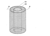
- FIG. 2 is a schematic view (perspective view) showing an example of a double tube nozzle in the optical fiber manufacturing apparatus of the present invention.
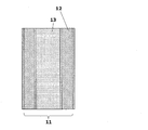
- FIG. 3 is a schematic view (an AA cross-sectional view in FIG. 2) showing an example of a double tube nozzle in the optical fiber manufacturing apparatus of the present invention.
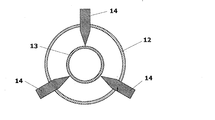
- FIG. 4 is a schematic diagram (cross-sectional view in the radial direction of the double tube nozzle) showing an example of the double tube nozzle provided with the position adjusting mechanism in the optical fiber manufacturing apparatus of the present invention.
- FIG. 1 is a schematic view showing an optical fiber manufacturing apparatus of the present invention and an embodiment for manufacturing an optical fiber using the manufacturing apparatus.
- FIG. 2 is a schematic view (perspective view) showing an example of a double tube nozzle in the optical fiber manufacturing apparatus of the present invention.
- FIG. 3 is a schematic view (an AA cross-
- FIG. 9 is a schematic view (perspective view) showing an example of a light shielding plate (conical light shielding plate) in the optical fiber manufacturing apparatus of the present invention.
- FIG. 10 is a schematic diagram (side view) for explaining the spread angle ⁇ of light emitted from the light irradiation device.
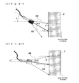
- FIG. 11 is a schematic diagram (side view) for explaining the relationship between the angle ⁇ formed by the direction of the light beam with the maximum irradiation intensity and the plane perpendicular to the discharge direction of the photocurable composition and the light spread angle ⁇ . .
- FIG. 11A is a schematic diagram in the case of ⁇ ⁇ ⁇ / 2
- FIG. 11B is a schematic diagram in the case of ⁇ ⁇ / 2.
- FIG. 11A is a schematic diagram in the case of ⁇ ⁇ ⁇ / 2
- FIG. 11B is a schematic diagram in the case of ⁇ ⁇ / 2.
- FIG. 12 is a schematic view (side view) showing an example of a light irradiation apparatus including an irradiation angle adjusting mechanism in the optical fiber manufacturing apparatus of the present invention.
- FIG. 13 is a schematic view showing an optical fiber manufacturing apparatus of the present invention and an embodiment (in the case of an epi-illumination system) for manufacturing an optical fiber using the manufacturing apparatus.
- FIG. 14 is a schematic diagram showing an optical fiber manufacturing apparatus (optical fiber manufacturing apparatus of the present invention) used in Example 1 and Example 2.
- FIG. 15 is a schematic diagram showing the optical fiber manufacturing apparatus used in Comparative Example 1.
- the said photocurable composition is a composition which hardens
- the photocurable composition for example, a known and commonly used photocurable composition (radical polymerizable composition, cationic polymerizable composition, anionic polymerizable composition, etc.) that is rapidly cured by light irradiation, or Specific photocurable compositions described later can be used.
- the said photocurable composition is an ultraviolet curable composition hardened
- the photocurable composition is liquid at room temperature (about 25 ° C.). That is, it is a liquid material having fluidity at room temperature.
- the photocurable composition By using the photocurable composition as a raw material for an optical fiber, spinning can be performed at room temperature without reducing the viscosity by heating or using a solvent. Furthermore, since impurities in the photocurable composition can be easily removed by filtration, it is easy to obtain a high-quality optical fiber.
- a composition (resin composition) that is solid at room temperature is used as a raw material for an optical fiber, spinning at room temperature is difficult unless the viscosity is lowered by heating or using a solvent, which is disadvantageous in terms of cost.
- a composition (resin composition) that is solid at room temperature has a complicated operation for removing impurities.
- E-type viscometer (trade name “VISCONIC”, manufactured by Tokimec Co., Ltd.) (rotor: 1 ° 34 ′ ⁇ R24, rotation speed: 0.5 rpm, measurement temperature: 25 ° C.).
- the optical fiber manufacturing apparatus of the present invention includes a nozzle for discharging the photocurable composition, and a light irradiation device for irradiating light to the filamentous photocurable composition discharged from the nozzle, and Control means for making the irradiation intensity of light at the discharge port of the nozzle be 0.2 mW / cm 2 or less is provided.
- the optical fiber manufacturing apparatus of the present invention will be described below with reference to the drawings as necessary.
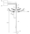
- FIG. 1 is a schematic view showing an optical fiber manufacturing apparatus of the present invention and an embodiment for manufacturing an optical fiber using the manufacturing apparatus.
- the optical fiber manufacturing apparatus according to the present invention includes a nozzle 1 and a light irradiation device 4 arranged so as to emit light below a discharge port 11 at a tip portion of the nozzle 1.
- the light irradiation device 4 in FIG. 1 includes a light source device 43 that outputs light, a light guide 42 that transmits the light, and a light guide tip 41 that emits light from an end (output end). .
- the photocurable composition 2 is discharged vertically from the discharge port 11 of the nozzle 1, and then the photocurable composition suspended from the nozzle 1.
- the object 2 is irradiated with light by the light irradiation device 4. Thereby, the photocurable composition 2 hardens
- the nozzle in the optical fiber manufacturing apparatus of the present invention plays a role of passing the photocurable composition through the inside thereof and discharging it from the discharge port.
- the photocurable composition discharged from the discharge port of the nozzle is usually formed in a thread shape (fiber shape) having a small diameter.
- the shape of the nozzle is not particularly limited as long as it is cylindrical.
- the nozzle may be cylindrical or rectangular.
- a cylindrical shape is preferable from the viewpoint of producing an optical fiber with low propagation loss.
- the material of the nozzle is not particularly limited, and examples thereof include SUS, aluminum, and resin. Among these, SUS is preferable from the viewpoint of durability and strength.
- the nozzle is preferably a double-tube nozzle having an outer tube and an inner tube disposed inside the outer tube from the viewpoint of aligning the center of the optical fiber core and the clad.
- the double pipe nozzle is a cylindrical (particularly cylindrical) inner pipe having an outer diameter smaller than the inner diameter of the outer pipe inside the cylindrical (particularly cylindrical) outer pipe.
- a nozzle having a double-pipe structure in which is arranged. 2 and 3 are schematic views showing an example of a double tube nozzle, FIG. 2 is a perspective view, and FIG. 3 is a cross-sectional view taken along line AA in FIG. 2 and 3, 12 represents an outer tube, and 13 represents an inner tube.
- a photocurable composition (sometimes referred to as a “core agent”) that forms a core inside the inner tube 13 is passed through, and the outer tube 12 and the inner tube 13 are passed through.
- a photocurable composition (sometimes referred to as “clad agent”) that forms a clad between the core agent and the clad agent, the core agent and the clad agent can be simultaneously ejected from the ejection port 11 of the nozzle.
- these photocurable compositions core agent and clad agent
- these photocurable compositions are irradiated with light and cured, so that an optical fiber having a core-clad structure in one step (optical fiber having a double-layer structure of core and clad). Can be manufactured.
- the diameter of the outer tube (inner diameter and outer diameter), the diameter of the inner tube (inner diameter and outer diameter), the core diameter and cladding diameter of the optical fiber to be manufactured, the viscosity and the discharge speed of the photocurable composition. It can select suitably by etc., and is not specifically limited.
- the inner diameter of the outer tube in the double tube nozzle is preferably 2 to 8 mm, and more preferably 2.4 to 5.4 mm.
- the outer diameter of the inner tube in the double tube nozzle is preferably, for example, 1 to 7 mm, more preferably 1.5 to 4 mm, and the inner diameter of the inner tube is, for example, 0.6 to 6.4 mm.
- the thickness is preferably 1.1 to 3.4 mm.
- the axis of the outer tube (center axis) and the axis of the inner tube (center axis) coincide at least at the distal end portion on the discharge port side.
- the double pipe nozzle is sometimes referred to as an adjustment mechanism ("position adjustment mechanism") for adjusting the position of the inner pipe inside the outer pipe in order to match the axis of the outer pipe with the axis of the inner pipe. ) Is preferable.
- the position adjustment mechanism is not particularly limited as long as the position of the inner tube can be adjusted.
- a screw adjustment screw
- FIG. 4 is a schematic diagram (cross-sectional view in the radial direction of the double tube nozzle) illustrating an example of the double tube nozzle provided with the position adjusting mechanism.
- 14 represents an adjusting screw.
- FIG. 4 represents an adjusting screw.
- the position adjusting mechanism is configured by bringing the tips of three adjusting screws into contact with the inner tube at equal intervals, and the screwing degree of these adjusting screws is adjusted to adjust the outer tube. It is possible to adjust the position of the inner tube inside.
- the size, number, and arrangement of the adjusting screws to be used are not limited to this.
- the light irradiation apparatus in the optical fiber manufacturing apparatus of the present invention plays a role of irradiating and curing light to the filamentous photocurable composition discharged from the nozzle.
- An optical fiber is obtained by curing the thread-shaped photocurable composition extending from the nozzle outlet.
- the light irradiated by the light irradiation device is not particularly limited as long as it can cure the photocurable composition, and for example, ultraviolet rays, infrared rays, visible rays, electron beams, and the like can be used. Among these, ultraviolet rays are preferable from the viewpoint that a general photoinitiator can be used. That is, the light irradiation device in the optical fiber manufacturing apparatus of the present invention is preferably an ultraviolet irradiation device.
- the said light irradiation apparatus uses the well-known and usual light irradiation apparatus which radiate
- a light irradiation device (ultraviolet irradiation device) that emits ultraviolet light
- a light source such as a high pressure mercury lamp, an ultrahigh pressure mercury lamp, a xenon lamp, a carbon arc, a metal halide lamp, sunlight, an LED lamp, or a laser.
- a light irradiation device that combines these light sources with a light guide for transmitting light output from the light sources, and a combination of these with various optical systems (for example, lenses, mirrors, etc.) Can be used as
- emits light may be called an "emitted part.”
- the end portion (output end) of the tip portion 41 of the light guide is the emission portion.
- the method of irradiating light to the photocurable composition using the light irradiation device is not particularly limited.
- the arrangement and number of the emitting portions of the light irradiation device are not particularly limited.
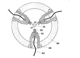
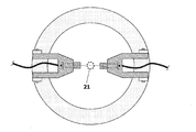
- FIG. 5 is a schematic view (plan view) showing an example of a light irradiation device in the optical fiber manufacturing apparatus of the present invention.
- the light irradiation apparatus in FIG. 5 is a light irradiation apparatus that emits light from three directions below the nozzle outlet and irradiates the photocurable composition.
- the said light irradiation apparatus has the emission part (output end of the front-end
- 21 represents a position through which the photocurable composition passes
- 44 and 45 represent a base (support) for fixing the tip portion 41 of the light guide of the light irradiation device in the optical fiber manufacturing apparatus of the present invention.
- the light irradiation device is not limited to this.
- the light irradiation device may irradiate light from two directions like the light irradiation device shown in FIG. What irradiates light from four or more directions may be used. Further, the light irradiation device is not limited to one that emits light below the nozzle outlet, but may be one that emits light from above the nozzle outlet (see, for example, FIG. 13).
- the optical fiber manufacturing apparatus of the present invention includes not only the above-described nozzle and light irradiation device, but also the light irradiation intensity at the nozzle outlet (hereinafter simply referred to as “light irradiation intensity at the outlet”). And a control means for setting the ratio to 0.2 mW / cm 2 or less.
- the above “irradiation intensity of light at the discharge port” means that light is emitted from the light irradiation device in the optical fiber manufacturing apparatus of the present invention under exactly the same apparatus configuration and conditions as in the optical fiber manufacturing except that the photocurable composition is not fed.
- the method for measuring the irradiation intensity is not particularly limited, and can be measured using, for example, a power meter (trade name “UV light meter UTI-250”, manufactured by USHIO INC.).
- the irradiation intensity of light at the discharge port is not particularly limited as long as it is controlled to 0.2 mW / cm 2 or less, but is 0 from the viewpoint of obtaining an optical fiber with a uniform wire diameter and preventing yarn breakage during production. .1 mW / cm 2 or less is preferable.
- the light irradiation intensity at the discharge port exceeds 0.2 mW / cm 2 , the curing reaction (polymerization reaction) of the photocurable composition proceeds at the discharge port at the tip of the nozzle, and the photocurable composition near the discharge port.
- the viscosity of the product may fluctuate or clog.
- the diameter of the photocurable composition discharged from the nozzle is not stable, and an optical fiber having a constant line diameter cannot be obtained, or yarn breakage frequently occurs during production, resulting in a decrease in productivity of the optical fiber.
- the control means is not particularly limited as long as the light irradiation intensity at the discharge port can be controlled to 0.2 mW / cm 2 or less.
- FIG. 7 shows a cylindrical light shielding member 51 (sometimes referred to as a “light shielding cylinder”) as an example of the light shielding member.
- a cylindrical light shielding member 51 (sometimes referred to as a “light shielding cylinder”) as an example of the light shielding member.
- the material for forming the light shielding member such as the light shielding cylinder and the light shielding plate is not particularly limited.
- SUS SUS, aluminum, resin, paper, etc.
- the light shielding member is not particularly limited, but is preferably black from the viewpoint of preventing light reflection.
- the light irradiation angle with respect to the photocurable composition falls within a specific range. It is preferably controlled. Specifically, in the optical fiber manufacturing apparatus of the present invention, the plane (plane) perpendicular to the direction of the light beam having the maximum irradiation intensity among the light beams emitted from the light irradiation device and the discharge direction of the photocurable composition. It is preferable that the minimum value ⁇ of the angle between the two is controlled so as to satisfy the relationship of the following formula (I).
- ⁇ is the maximum value of the angles formed by the light beams whose irradiation intensity is 3% of the maximum value among the light beams emitted from the light irradiation device (sometimes referred to as “divergence angle”). It is.
- FIG. 10 is a schematic diagram (side view, using a light shielding tube) for explaining the spread angle ⁇ of the light emitted from the light irradiation device.
- 61 indicates the maximum intensity light
- 62 indicates a light beam whose irradiation intensity is 3% of the maximum intensity light.
- the spread angle ⁇ is defined by the maximum value 63 of the angle formed by the light beams whose irradiation intensity is 3% of the maximum intensity light.
- the spread angle ⁇ tends to be small by covering the emitting portion with a light shielding tube.
- the above ⁇ can be derived, for example, by measuring the light intensity distribution at a certain distance (for example, 1.5 cm) from the emitting portion.
- the light intensity distribution can be measured by, for example, using an ultraviolet light meter and moving the light receiver little by little from the center of the irradiation light (the front of the center of the emitting portion) toward the peripheral portion.
- the minimum value ⁇ of the angle formed by the direction of the maximum intensity light emitted from the light irradiation device and the surface perpendicular to the discharge direction of the photocurable composition is expressed by the above formula (I).
- FIG. 11 is a schematic diagram (side view) for explaining the relationship between the minimum value ⁇ of the angle formed by the direction of the maximum intensity light and the surface perpendicular to the discharge direction of the photocurable composition and the light spread angle ⁇ .
- FIG. 13 is a schematic view showing an optical fiber manufacturing apparatus of the present invention and an embodiment (in the case of an epi-illumination system) for manufacturing an optical fiber using the manufacturing apparatus.
- the optical fiber manufacturing apparatus of the present invention in FIG. 13 is a schematic view showing an optical fiber manufacturing apparatus of the present invention and an embodiment (in the case of an epi-illumination system) for manufacturing an optical fiber using the manufacturing apparatus.
- the light irradiation device includes a light guide tip portion that emits light from a light source device 43 that outputs light, a light guide 42 that transmits the light, and a light guide tip portion 41 that emits light from an end portion (output end).
- a reflection mirror 47 that reflects light emitted from the output terminal 41 downward and a condenser lens 48 that condenses the reflected light are provided.
- Reference numeral 54 in FIG. 13 denotes a ring-shaped light shielding member (sometimes referred to as a “light shielding ring”). By mounting such a light shielding ring above the tip of the nozzle, light irradiation at the discharge port 11 of the nozzle 1 is performed. The intensity is controlled to 0.2 mW / cm 2 or less.
- the optical fiber manufacturing apparatus of the present invention is an epi-illumination type optical fiber manufacturing apparatus, as shown in FIG. 13, it is easy to form a shadow on the nozzle outlet by using the light shielding ring 54, and the nozzle is more efficiently used. There is an advantage that the irradiation intensity of light at the discharge port can be lowered.
- the distance between the photocurable composition and the emission part of the light irradiation device is relatively long, it is difficult to irradiate the photocurable composition with high-intensity light, improving the productivity. There are disadvantages that are difficult to make.
- the method for producing an optical fiber of the present invention is a method for producing an optical fiber by irradiating light to a photocurable composition and curing it, and discharging the photocurable composition using a nozzle, and then from the nozzle. Including a step of irradiating the discharged filamentary photocurable composition with light using a light irradiation device, and in the step, the irradiation intensity of light at the nozzle outlet is 0.2 mW / cm 2 or less. It is characterized by control.
- the nozzle is not particularly limited, and for example, the nozzle exemplified in the above-mentioned section of the optical fiber manufacturing apparatus of the present invention can be used.
- the optical fiber manufacturing method of the present invention manufactures an optical fiber having a core-clad structure by using a double-tube nozzle having an outer tube and an inner tube arranged inside the outer tube as the nozzle. It is preferable that it is a method to do.
- the double tube nozzle those exemplified in the above-mentioned section of the optical fiber production apparatus of the present invention can be preferably used.
- the core agent and the clad agent can be simultaneously ejected from the nozzle, and then these photocurable compositions (core agent and clad agent) are irradiated with light and cured.
- an optical fiber having a core-clad structure can be manufactured in one step.
- the light irradiation device is not particularly limited as long as it can emit light capable of curing the photocurable composition, and for example, the one exemplified in the section of the optical fiber manufacturing device of the present invention described above. Can be used.
- the total discharge rate of the core agent and the clad agent at this time is not particularly limited, but is preferably 0.3 to 1 mL / min, and more preferably 0.375 to 0.6 mL / min, for example.
- the core diameter and clad diameter of an optical fiber can be controlled independently by controlling the discharge rate of a core agent and a clad agent independently.
- a metering pump exemplified in the above-mentioned section of the optical fiber manufacturing apparatus of the present invention can be used for controlling the discharge speed.
- the above ⁇ (the minimum value ⁇ of the angle formed between the direction of the maximum intensity light and the surface perpendicular to the discharge direction of the photocurable composition) is, for example, the light guide tip portion of the light irradiation device.
- the angle can be controlled by tilting toward the discharge direction side (for example, downward) of the photocurable composition with respect to a plane (usually a horizontal plane) orthogonal to the discharge direction of the photocurable composition.
- the above ⁇ (expansion angle) can be derived by the above-described method.
- the optical fiber obtained by curing the photocurable composition is not particularly limited, but can be recovered by appropriately winding up.
- the winding speed at this time is not particularly limited, but is preferably, for example, 10 to 1000 mm / second, and more preferably 100 to 500 mm / second.
- the winding speed can be controlled by using, for example, the above-described winding device.
- optical fiber manufacturing method of the present invention other devices and apparatuses (for example, a heating unit, a cooling unit, a fiber diameter measuring device, a fiber tension measuring device, etc.) are used in the same manner as the optical fiber manufacturing device of the present invention described above. It can also be used as appropriate.
- devices and apparatuses for example, a heating unit, a cooling unit, a fiber diameter measuring device, a fiber tension measuring device, etc.
- the optical fiber of the present invention is an optical fiber manufactured by the method described above (the optical fiber manufacturing method of the present invention).
- the photocurable composition as a raw material of the optical fiber of the present invention is not particularly limited, from the viewpoint of heat resistance and mechanical properties, the weight of the oxetane ring-containing (meth) acrylic acid ester compound represented by the following formula (1) It is preferable to contain a polymer or copolymer as an essential component.
- the photocurable composition that forms the core and the photocurable composition that forms the cladding are both oxetane ring-containing (meth) acrylate compounds represented by the following formula (1): It is preferable that it is a photocurable resin composition containing the polymer or copolymer of this as an essential component.
- the photocurable resin composition is a radical polymerized oxetane ring-containing (meth) acrylic acid ester compound represented by the following formula (1) alone or with other compounds having radical polymerizability. Obtained by cationic polymerization of the cation-polymerizable resin obtained by the above or the oxetane ring-containing (meth) acrylic acid ester compound represented by the following formula (1) alone or with other compounds having cationic polymerizability. It is preferable to include a radical polymerizable resin as an essential component.
- the photocurable resin composition is an oxetane ring-containing (meth) acrylic acid ester compound represented by the following formula (1) alone or has radical polymerizability. It is preferable that it is a photocurable resin composition (cationic polymerizable resin composition) which contains the cationically polymerizable resin obtained by radical polymerization with the other compound which has as an essential component.
- the oxetane ring-containing (meth) acrylic acid ester compound is represented by the following formula (1).
- R 1 and R 2 are the same or different and each represents a hydrogen atom or an alkyl group, and A represents a linear or branched alkylene group having 2 to 20 carbon atoms.
- the alkyl group in R 1 and R 2 is preferably an alkyl group having 1 to 6 carbon atoms.
- a straight chain such as a methyl group, an ethyl group, a propyl group, a butyl group, a pentyl group, or a hexyl group Chain C 1-6 (preferably C 1-3 ) alkyl group; isopropyl group, isobutyl group, s-butyl group, t-butyl group, isopentyl group, s-pentyl group, t-pentyl group, isohexyl group, Examples thereof include branched C 1-6 (preferably C 1-3 ) alkyl groups such as s-hexyl group and t-hexyl group.
- R 1 is preferably a hydrogen atom or a methyl group
- R 2 is preferably a methyl group or an ethyl group.
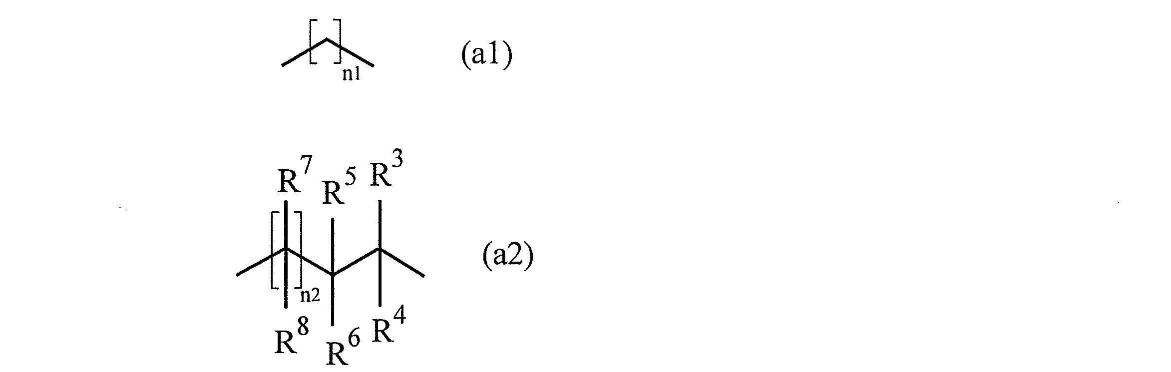
- A represents a linear or branched alkylene group having 2 to 20 carbon atoms.
- a linear alkylene group represented by the following formula (a1) or a branched chain represented by the following formula (a2) is capable of forming an optical fiber having both excellent heat resistance and flexibility.
- An alkylene group is preferred.
- the right end of the formula (a2) is bonded to an oxygen atom constituting an ester bond.
- n1 represents an integer of 2 or more.
- R 3 , R 4 , R 7 and R 8 are the same or different and represent a hydrogen atom or an alkyl group
- R 5 and R 6 are the same or different and represent an alkyl group.
- n2 represents an integer of 0 or more, and when n2 is an integer of 2 or more, 2 or more of R 7 and R 8 may be the same or different.
- N1 in the formula (a1) represents an integer of 2 or more, preferably an integer of 2 to 20, and particularly preferably an integer of 2 to 10.
- n1 1, the flexibility of the cured product obtained by polymerization tends to decrease.
- the alkyl group in R 3 , R 4 , R 5 , R 6 , R 7 , R 8 in the formula (a2) is not particularly limited, but an alkyl group having 1 to 4 carbon atoms is preferable, and examples thereof include a methyl group, Linear C 1-4 (preferably C 1-3 ) alkyl groups such as ethyl, propyl and butyl; branched chains such as isopropyl, isobutyl, s-butyl and t-butyl Examples thereof include C 1-4 (preferably C 1-3 ) alkyl groups.
- R 3 and R 4 are preferably a hydrogen atom
- R 5 and R 6 are preferably a methyl group and an ethyl group.
- N2 in the formula (a2) represents an integer of 0 or more, preferably an integer of 1 to 20, and particularly preferably an integer of 1 to 10.
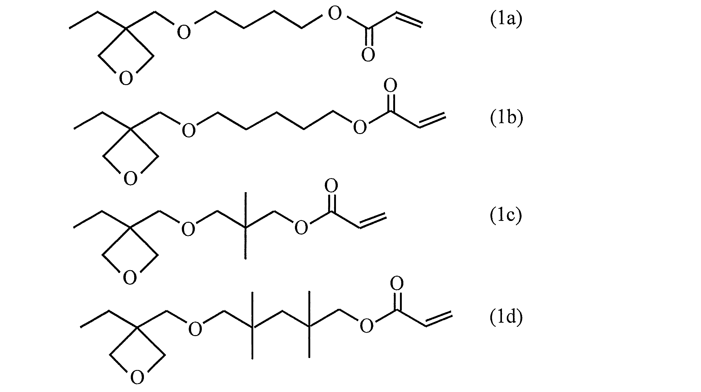
- Typical examples of the oxetane ring-containing (meth) acrylic acid ester compound represented by the formula (1) include the following compounds.
- the oxetane ring-containing (meth) acrylic acid ester compound represented by the formula (1) is, for example, the following formula (2) (In formula (2), R 2 is the same as above. X represents a leaving group) And a compound represented by the following formula (3) (In formula (3), A is the same as above) A compound represented by the following formula (4) is reacted in a liquid phase one-phase system in the presence of a basic substance. (Formula (4), R 2 and A are the same as above) It can be synthesized by obtaining an oxetane ring-containing alcohol represented by the formula (1) and (meth) acrylating the obtained oxetane ring-containing alcohol.
- X represents a leaving group, for example, a halogen atom such as chlorine, bromine and iodine (among others, a bromine atom and an iodine atom are preferred); a p-toluenesulfonyloxy group, a methanesulfonyloxy group, Examples thereof include a sulfonyloxy group such as a trifluoromethanesulfonyloxy group; a group having a high leaving property such as a carbonyloxy group such as an acetyloxy group.
- a halogen atom such as chlorine, bromine and iodine (among others, a bromine atom and an iodine atom are preferred)
- a p-toluenesulfonyloxy group such as a trifluoromethanesulfonyloxy group
- a group having a high leaving property such as a carbonyloxy group such as an
- Examples of the basic substance include alkali metal or alkaline earth metal hydroxides such as sodium hydroxide, potassium hydroxide, calcium hydroxide, and magnesium hydroxide; sodium hydride, magnesium hydride, calcium hydride, and the like.
- liquid phase single phase system means a case where the liquid phase is not a single phase or more but only a single phase, and may contain a solid if the liquid phase is a single phase.
- the solvent is not limited as long as it can dissolve both the compound represented by the formula (2) and the compound represented by the formula (3).
- aromatic hydrocarbons such as benzene, toluene, xylene, and ethylbenzene Ethers such as THF (tetrahydrofuran) and IPE (isopropyl ether); sulfur-containing solvents such as DMSO (dimethyl sulfoxide); nitrogen-containing solvents such as DMF (dimethylformamide) and the like.
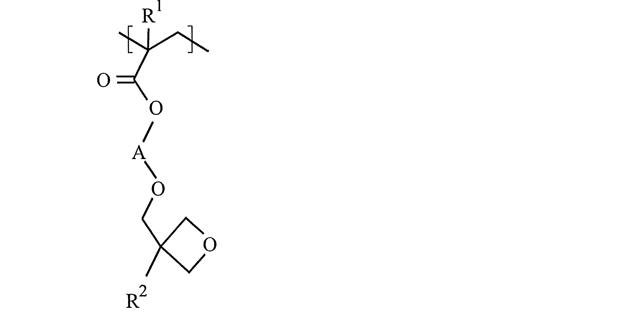
- the cationically polymerizable resin is obtained by radical polymerization of the oxetane ring-containing (meth) acrylic acid ester compound represented by the formula (1) alone or with other compounds having radical polymerizability.
- the “other compound having radical polymerizability” is a compound having radical polymerizability and different from the oxetane ring-containing (meth) acrylic acid ester compound represented by the above formula (1).
- a cationically polymerizable resin represented by the following formula can be synthesized by radical polymerization or radical copolymerization with other radical polymerizable compounds.
- the radical copolymerization includes block copolymerization, random copolymerization and the like.
- the oxetane ring-containing (meth) acrylic acid ester compound represented by the above formula (1) and other radical polymerizable compounds are particularly preferable in that a cured product having more flexibility can be formed.
- Cationic polymerizable resins are preferred.
- radical polymerizable compounds include, for example, radical polymerizable groups such as (meth) acryloyl group, (meth) acryloyloxy group, (meth) acryloylamino group, vinyl ether group, vinylaryl group, vinyloxycarbonyl group and the like.
- radical polymerizable groups such as (meth) acryloyl group, (meth) acryloyloxy group, (meth) acryloylamino group, vinyl ether group, vinylaryl group, vinyloxycarbonyl group and the like.
- numerator can be mentioned.
- Examples of the compound having one or more (meth) acryloyl groups in one molecule include 1-buten-3-one, 1-penten-3-one, 1-hexen-3-one, and 4-phenyl-1- Examples thereof include buten-3-one, 5-phenyl-1-penten-3-one, and derivatives thereof.
- Examples of the compound having one or more (meth) acryloyloxy groups in one molecule include methyl (meth) acrylate, ethyl (meth) acrylate, n-butyl (meth) acrylate, isobutyl (meth) acrylate, and t-butyl.
- Examples of the compound having one or more (meth) acryloylamino groups in one molecule include morpholin-4-yl acrylate, acryloylmorpholine, N, N-dimethylacrylamide, N, N-diethylacrylamide, and N-methylacrylamide.
- Examples of the compound having one or more vinyl ether groups in one molecule include 2-hydroxyethyl vinyl ether, 3-hydroxypropyl vinyl ether, 2-hydroxypropyl vinyl ether, 2-hydroxyisopropyl vinyl ether, 4-hydroxybutyl vinyl ether, 3-hydroxy Butyl vinyl ether, 2-hydroxybutyl vinyl ether, 3-hydroxyisobutyl vinyl ether, 2-hydroxyisobutyl vinyl ether, 1-methyl-3-hydroxypropyl vinyl ether, 1-methyl-2-hydroxypropyl vinyl ether, 1-hydroxymethylpropyl vinyl ether, 4- Hydroxycyclohexyl vinyl ether, 1,6-hexanediol monovinyl ether, 1,4-cyclohexanedi Tanol monovinyl ether, 1,3-cyclohexanedimethanol monovinyl ether, 1,2-cyclohexanedimethanol monovinyl ether, p-xylene glycol monovinyl ether, m-xylene glycol monoviny
- Examples of the compound having one or more vinylaryl groups in one molecule include styrene, divinylbenzene, methoxystyrene, ethoxystyrene, hydroxystyrene, vinylnaphthalene, vinylanthracene, 4-vinylphenyl acetate, (4-vinylphenyl) Dihydroxyborane, (4-vinylphenyl) boranoic acid, (4-vinylphenyl) boronic acid, 4-ethenylphenylboronic acid, 4-vinylphenylboranoic acid, 4-vinylphenylboronic acid, p-vinylphenylboric acid, Examples thereof include p-vinylphenylboronic acid, N- (4-vinylphenyl) maleimide, N- (p-vinylphenyl) maleimide, N- (p-vinylphenyl) maleimide, and derivatives thereof. .
- Examples of the compound having one or more vinyloxycarbonyl groups in one molecule include, for example, isopropenyl formate, isopropenyl acetate, isopropenyl propionate, isopropenyl butyrate, isopropenyl isobutyrate, isopropenyl caproate, and isopropenyl valerate.
- (meth) acryloyl group, (meth) acryloyloxy group, (meth) can be formed in one molecule because an optical fiber excellent in flexibility and heat resistance can be formed.
- a compound having only one functional group selected from an acryloylamino group, a vinylaryl group, a vinyl ether group, and a vinyloxycarbonyl group is preferred.
- n-butyl (meth) acrylate isobutyl (meth) acrylate, t-butyl methacrylate
- Compounds having only one (meth) acryloyloxy group in one molecule such as n-hexyl (meth) acrylate and 2-ethylhexyl (meth) acrylate are preferred. These can be used alone or in admixture of two or more.
- the radical polymerization reaction can be accelerated by heat treatment and / or light irradiation.
- the temperature can be appropriately adjusted according to the components to be subjected to the reaction and the kind of the catalyst, and is preferably 20 to 200 ° C., more preferably 50 to 150 ° C., and further preferably It is about 70 to 120 ° C.
- the light source for example, a mercury lamp, a xenon lamp, a carbon arc lamp, a metal halide lamp, sunlight, an electron beam, a laser beam, or the like can be used.
- a heat treatment may be performed at a temperature of about 50 to 180 ° C. to advance the radical polymerization reaction.
- the radical polymerization reaction is usually performed in the presence of a solvent.
- a solvent examples include 1-methoxy-2-acetoxypropane (PGMEA), benzene, toluene and the like.
- a polymerization initiator may be used for the radical polymerization reaction.
- the polymerization initiator those that can cause radical polymerization such as known and commonly used thermal polymerization initiators and photo radical polymerization initiators can be used without particular limitation, and examples thereof include benzoyl peroxide, azobisiso Examples include butyronitrile (AIBN), azobis-2,4-dimethylvaleronitrile, 2,2'-azobis (isobutyric acid) dimethyl, and the like.
- the amount of the polymerization initiator used in the radical polymerization reaction is not particularly limited, but the radical polymerizable compound (the total of the oxetane ring-containing (meth) acrylic acid ester compound represented by the formula (1) and other radical polymerizable compounds).
- Weight (100 parts by weight), for example, 0.01 to 50 parts by weight is preferable, and 0.1 to 20 parts by weight is more preferable.
- the weight average molecular weight of the cationic polymerizable resin is not particularly limited, but is preferably 500 or more (for example, 500 to 1,000,000), more preferably 3000 to 500,000. If the weight average molecular weight of the cationic polymerizable resin is out of the above range, the flexibility of the optical fiber obtained by curing the cationic polymerizable resin composition tends to be difficult to obtain.
- the number average molecular weight of the cationic polymerizable resin is not particularly limited, but is preferably 100 or more (for example, 100 to 500,000), more preferably 300 to 250,000. If the number average molecular weight of the cationic polymerizable resin is out of the above range, the flexibility of the optical fiber obtained by curing the cationic polymerizable resin composition tends to be difficult to obtain.
- the weight average molecular weight and number average molecular weight of the said cation polymeric resin can be measured as a value of standard polystyrene conversion by GPC (gel permeation chromatography) method, for example.
- the cationic polymerizable resin composition contains the cationic polymerizable resin as an essential component.
- the proportion (content) of the cationic polymerizable resin in the cationic polymerizable resin composition is not particularly limited, but is preferably 5% by weight or more, and the cationic polymerizable resin composition is substantially composed only of the cationic polymerizable resin. It may be configured.
- the proportion of the cationic polymerizable resin is preferably 10 to 95% by weight, and more preferably 40 to 95% by weight in that an optical fiber having more flexibility can be formed.
- the proportion of the cationic polymerizable resin is less than 5% by weight, the flexibility of the optical fiber obtained by curing by cationic polymerization tends to be lowered.
- the cationic polymerizable resin composition is a compound having cationic polymerizability, which is an oxetane ring-containing (meth) acrylic acid ester compound represented by the above formula (1). It may contain different compounds (hereinafter may be referred to as “other cationically polymerizable compounds”).
- Examples of other cationically polymerizable compounds include compounds having one or more cationically polymerizable groups such as oxetane ring, epoxy ring, vinyl ether group, and vinylaryl group in one molecule.
- Examples of the compound having one or more oxetane rings in one molecule include 3,3-bis (vinyloxymethyl) oxetane, 3-ethyl-3-hydroxymethyloxetane, 3-ethyl-3- (2-ethylhexyloxy).
- Examples of compounds having one or more epoxy rings in one molecule include bisphenol A diglycidyl ether, bisphenol F diglycidyl ether, bisphenol S diglycidyl ether, brominated bisphenol A diglycidyl ether, and brominated bisphenol F diglycidyl ether.
- Examples of the compound having one or more vinyl ether groups in one molecule and the compound having one or more vinyl aryl groups in one molecule can include the same examples as those mentioned in the above other radical polymerizable compounds. .
- the above cationic polymerizable resin composition preferably contains another cationic polymerizable compound together with the above cationic polymerizable resin in that an optical fiber having more flexibility can be formed.
- the blending ratio of the cationic polymerizable resin and the other cationic polymerizable compound is not particularly limited, but is preferably 95/5 to 10/90, more preferably 95/5 to 20/80. More preferably, it is 95/5 to 45/55. If the proportion of the cationic polymerizable resin is less than the above range, the flexibility of the resulting optical fiber tends to decrease.
- the cationic polymerizable resin composition may contain a polymerization initiator as necessary.
- a polymerization initiator what can raise
- polymerization initiator examples include sulfonium salts such as triallylsulfonium hexafluorophosphate and triarylsulfonium hexafluoroantimonate; diaryliodonium hexafluorophosphate, diphenyliodonium hexafluoroantimonate, bis (dodecylphenyl) iodonium tetrakis (pentafluoro) Examples thereof include iodonium salts such as phenyl) borate and iodonium [4- (4-methylphenyl-2-methylpropyl) phenyl] hexafluorophosphate; phosphonium salts such as tetrafluorophosphonium hexafluorophosphate; pyridium salts and the like.
- sulfonium salts such as triallylsulfonium hexafluorophosphate and triarylsulfonium he
- the photoacid generator a commercially available product such as a trade name “CPI-100P” (manufactured by San Apro Co., Ltd.) may be used.
- the amount of the polymerization initiator used in the cationic polymerization reaction is 0.01 to 50 parts by weight with respect to the cationically polymerizable compound (total weight of the cationically polymerizable resin and other cationically polymerizable compounds) (100 parts by weight).
- the amount is preferably 0.1 to 20 parts by weight.
- additives may be added to the cationic polymerizable resin composition as necessary within a range not impairing the effects of the present invention.
- Other additives include, for example, curing-expandable monomers, photosensitizers (anthracene sensitizers, etc.), resins, adhesion improvers, reinforcing agents, softeners, plasticizers, viscosity modifiers, solvents, inorganic Or well-known and usual various additives, such as organic particle
- an oxetane ring-containing (meth) acrylic acid ester compound represented by the formula (1) is used as a photocurable composition as a raw material of the optical fiber of the present invention.
- a photo-curable resin composition (radical polymerizable resin composition) containing, as an essential component, a radical polymerizable resin obtained by cation polymerization alone or with other compounds having other cationic polymerization properties (other cationic polymerizable compounds) can also be used.
- the radical polymerizable resin composition it is necessary to perform light irradiation in an atmosphere of a gas inert to radicals (for example, in a nitrogen atmosphere) in order not to inhibit the curing reaction.
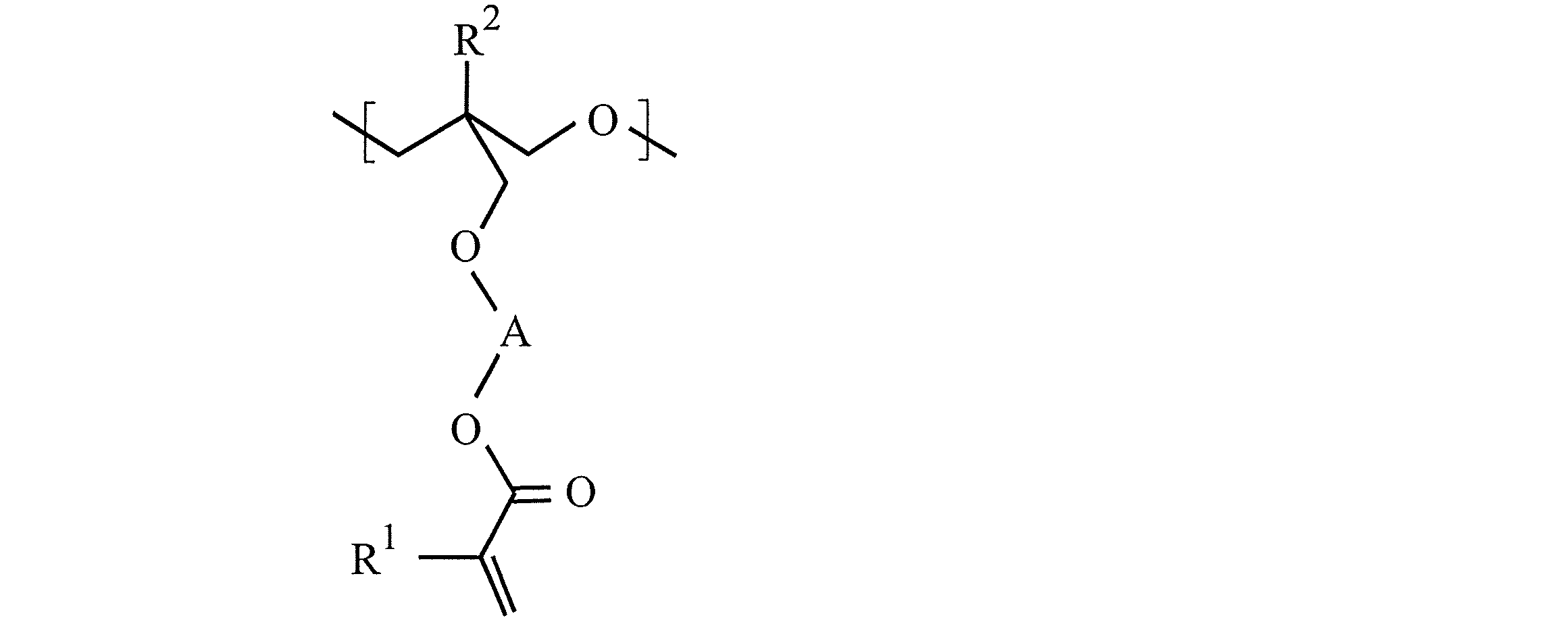
- the radical polymerizable resin is a cation polymerized oxetane ring-containing (meth) acrylic acid ester compound represented by the formula (1) alone or with other compounds having other cationic polymerization properties (other cationic polymerizable compounds). Obtained.
- a radical polymerizable resin represented by the following formula can be synthesized by cationic polymerization or cationic copolymerization with other cationic polymerizable compounds.
- block copolymerization, random copolymerization, etc. are contained in cationic copolymerization.
- the oxetane ring-containing (meth) acrylic acid ester compound represented by the above formula (1) and other cations are particularly preferable in that a cured product (optical fiber) having more flexibility can be formed.
- a radical polymerizable resin obtained by cationic copolymerization of a polymerizable compound is preferred.
- the proportion of the monomer derived from the oxetane ring-containing (meth) acrylic acid ester compound represented by the formula (1) among all monomers constituting the radical polymerizable resin is 0.1% by weight or more (preferably 1 to A resin obtained by cationic copolymerization at a ratio of 99 wt%, particularly preferably 10 to 80 wt%, is preferred.
- Examples of the other cationic polymerizable compound include one or more cationic polymerizable groups such as oxetane ring, epoxy ring, vinyl ether group, and vinyl aryl group exemplified in the section of the cationic polymerizable resin composition in one molecule. And the like.
- the other cationically polymerizable compound is selected from an oxetane ring, an epoxy ring, a vinyl ether group, and a vinylaryl group in one molecule because it can form a cured product having excellent flexibility and heat resistance.
- the cationic polymerization reaction is generally performed in the presence of a solvent.
- a solvent examples include benzene, toluene, xylene and the like.
- a polymerization initiator may be used for the cationic polymerization reaction.
- a polymerization initiator for example, a cationic polymerization initiator, an acid generator and the like exemplified in the section of the cationic polymerizable resin composition can be used.
- the amount of the polymerization initiator used in the cationic polymerization reaction is, for example, a cationic polymerizable compound (total weight of the oxetane ring-containing (meth) acrylic acid ester compound represented by the formula (1) and other cationic polymerizable compounds) ( For example, 0.01 to 50 parts by weight is preferable, and 0.1 to 20 parts by weight is more preferable.
- a cationic polymerizable compound total weight of the oxetane ring-containing (meth) acrylic acid ester compound represented by the formula (1) and other cationic polymerizable compounds
- the cationic polymerization reaction may be performed in the presence of a polymerization inhibitor.
- the polymerization inhibitor include 4-methoxyphenol, hydroquinone, methyl hydroquinone, dimethyl hydroquinone, trimethyl hydroquinone, hydroquinone monomethyl ether, 2,5-di-t-butyl hydroquinone, pt-butyl catechol, mono-t- Quinone / phenol inhibitors such as butyl hydroquinone, p-benzoquinone, naphthoquinone, 2,5-di-t-butyl-p-cresol, ⁇ -naphthol, nitrophenol, thioether inhibitors, phosphite inhibitors Etc.
- the weight average molecular weight of the radical polymerizable resin is not particularly limited, but is preferably 500 or more (for example, about 500 to 1,000,000), more preferably 3000 to 500,000.
- the weight average molecular weight of the radical polymerizable resin is less than the above range, the flexibility of the cured product (optical fiber) obtained by radical polymerization tends to decrease.
- the weight average molecular weight of the said radical polymerizable resin can be measured as a value of standard polystyrene conversion by GPC (gel permeation chromatography) method, for example.
- the radical polymerizable resin composition contains the radical polymerizable resin as an essential component.
- the ratio (content) of the radical polymerizable resin in the radical polymerizable resin composition is not particularly limited, but is preferably 5% by weight or more, and the radical polymerizable resin composition is substantially composed only of the radical polymerizable resin. It may be configured. Among them, the ratio of the radical polymerizable resin is preferably 10% by weight or more, more preferably 60 to 90% by weight, in that an optical fiber having more flexibility can be formed. If the ratio of the radical polymerizable resin is less than 5% by weight, the flexibility of the optical fiber obtained by curing by cationic polymerization tends to be lowered.
- the radical polymerizable resin composition includes a radical polymerizable compound, which is an oxetane ring-containing (meth) acrylic acid ester compound represented by the above formula (1). Different compounds (other radical polymerizable compounds) may be contained.
- Examples of the other radical polymerizable compound include (meth) acryloyl group, (meth) acryloyloxy group, (meth) acryloylamino group, vinylaryl group, vinyl ether group, vinyl exemplified in the above-mentioned section of the cationic polymerizable resin.
- Examples thereof include compounds having one or more radically polymerizable groups such as oxycarbonyl groups in one molecule.
- ethylene glycol di (meth) acrylate, diethylene glycol di (meth) acrylate, triethylene glycol di (()) are particularly preferable in that a cured product having better heat resistance can be formed.
- the radical polymerizable resin composition preferably contains another radical polymerizable compound together with the radical polymerizable resin in that an optical fiber having better heat resistance can be formed.
- the blending ratio (the former / the latter: weight ratio) of the radical polymerizable resin and the other radical polymerizable compound is preferably, for example, 95/5 to 5/95, more preferably 95/5 to 20/80, Preferably, it is 95/5 to 60/40.
- the blending ratio of the radical polymerizable resin is out of the above range, the flexibility of the obtained optical fiber tends to decrease.
- a polymerization initiator may or may not be added to the radical polymerizable resin composition.
- a polymerization initiator what can raise
- photo radical polymerization initiator examples include benzophenone, acetophenone benzyl, benzyl dimethyl ketone, benzoin, benzoin methyl ether, benzoin ethyl ether, benzoin isopropyl ether, dimethoxyacetophenone, dimethoxyphenylacetophenone, diethoxyacetophenone, diphenyl disulfite and the like. Can be mentioned. These can be used alone or in admixture of two or more.
- a synergist for enhancing the conversion of light absorption energy into polymerization initiation free radicals may be added to the polymerization initiator.
- the synergist include amines such as triethylamine, diethylamine, diethanolamine, ethanolamine, dimethylaminobenzoic acid, methyl dimethylaminobenzoate; ketones such as thioxanthone, 2-isopropylthioxanthone, 2,4-diethylthioxanthone, and acetylacetone. Can be mentioned.
- the amount added is a radical polymerizable compound in the radical polymerizable resin composition (total weight of the radical polymerizable resin and other radical polymerizable compounds).
- the amount is preferably 0.01 to 50 parts by weight, more preferably 0.1 to 20 parts by weight with respect to (100 parts by weight).
- additives may be added to the radical polymerizable resin composition as needed within the range not impairing the effects of the present invention.
- Other additives include, for example, curing-expandable monomers, photosensitizers (anthracene sensitizers, etc.), resins, adhesion improvers, reinforcing agents, softeners, plasticizers, viscosity modifiers, solvents, inorganic Or well-known and usual various additives, such as organic particle
- the core diameter (core diameter) is not particularly limited, but is preferably 10 to 999 ⁇ m, more preferably 50 to 100 ⁇ m.
- the diameter of the clad (cladding diameter) of the optical fiber of the present invention is not particularly limited, but is preferably 60 to 1000 ⁇ m, more preferably 100 to 500 ⁇ m.
- the optical fiber of the present invention can also be used by providing an appropriate coating layer outside the cladding.
- the coating layer include a coating layer made of polyimide, polypropylene, polyethylene, PTFE, polyvinyl chloride, or the like.
- the optical fiber of the present invention is manufactured by the optical fiber manufacturing method of the present invention. For this reason, the optical fiber of the present invention has a constant wire diameter and is excellent in quality. In addition, since the productivity is high, the cost is excellent. Furthermore, since the optical fiber of the present invention is made from a photocurable composition that is liquid at room temperature, impurities in the photocurable composition can be easily removed by filtration, making it easy to obtain a high-quality optical fiber. is there.
- the optical fiber of the present invention can accurately match the central axes of the core and the clad when the above-mentioned double tube nozzle is used as a nozzle for discharging the photocurable composition during production. It is possible to exhibit high reliability when connecting optical fibers or connecting with other devices. Furthermore, the optical fiber of the present invention has an optical fiber having a more uniform wire diameter and high productivity when the irradiation angle of light is controlled so as to satisfy the relationship of the above formula (I) at the time of manufacture. can do.
- the optical fiber of the present invention is widely used in optical communication applications and decorative applications.
- communication applications in portable devices, FA devices, OA devices, audio devices, vehicles, LANs, image transmission applications in home and industrial endoscopes, sensor applications, etc. It is particularly useful for light transmission for inspection / measurement lighting, lighting for works of art, etc., decoration for billboards, signs, landscape lighting, and the like.
- the core prepolymer had a weight average molecular weight in terms of polystyrene of 67600 and a number average molecular weight of 11,800.
- 60% by weight of the core prepolymer was mixed with 15% by weight of the trade name “OXT-212” (manufactured by Toagosei Co., Ltd.) and 25% by weight of “OXT-DVE”.
- a trade name “CPI-100P” (manufactured by San Apro Co., Ltd.) is mixed as an agent and mixed to form a photocurable composition for forming a core (photocurable resin composition) (core agent; 25 ° C.
- the viscosity at 15000 cP) was produced.
- the above “OXT-212” is 3-ethyl-3- (2-ethylhexyloxymethyl) oxetane.
- the above “OXT-DVE” is 3,3-bis (vinyloxymethyl) oxetane.
- CPI-100P includes diphenyl [4- (phenylthio) phenyl] sulfonium hexafluorophosphate, thiodi-p-phenylenebis (diphenylsulfonium), bis (hexafluorophosphate), propylene carbonate, and diphenyl sulfide. It is a mixture of
- the mixture was further maintained for 2 hours, and then cooled to 40 ° C. or lower to obtain a resin composition.
- a polymer (liquid resin) was obtained.
- the clad prepolymer had a polystyrene-reduced weight average molecular weight of 288,000 and a number average molecular weight of 61,200.
- Example 1 Optical fiber manufacturing equipment
- the manufacturing apparatus shown in FIG. 14 was used.
- 1 is a double tube nozzle.
- the inner diameters of the outer tube and the inner tube of the double tube nozzle 1 are as shown below.
- the light irradiation apparatus shown in FIG. 5 which can irradiate light from three directions with respect to the photocurable composition 2 was used as a light irradiation apparatus.
- the light irradiation device is equidistant with respect to the photocurable composition 2, and the tip portions of the three light guides (UV light guides) are equally spaced at the same height (120 ° centering on the photocurable composition). (See FIG.
- the distance from the output end (the center of the output end) of the tip portion 41 of the light guide to the photocurable composition 2 was set to 15 mm. Furthermore, the tip portion 41 of the light guide was installed by being inclined 11 ° downward with respect to the horizontal plane. In addition, the spread angle ⁇ of light emitted in a state where the front end portion 41 of the light guide is covered with the light shielding cylinder 51 is 22 °.
- a core agent was sent to the inner tube of the double tube nozzle 1, and a clad agent was fed between the outer tube and the inner tube.
- the core agent and the clad agent were irradiated with ultraviolet rays and cured by a light irradiation device.
- the optical fiber (plastic optical fiber) thus produced was collected by the winding device 8.
- Example 2 [Optical fiber manufacturing equipment] Similarly to Example 1, the optical fiber manufacturing apparatus shown in FIG. 14 was used. [Manufacture of optical fiber] An optical fiber was manufactured in the same manner as in Example 1 except that the feed rate of the core agent was changed as follows. (Experimental conditions) Light irradiation intensity at the nozzle outlet: 0.13 mW / cm 2 Core agent feed rate: 0.075 mL / min Clad agent feed rate: 0.3 mL / min Inner diameter (diameter) of inner tube of double tube nozzle: 1.6 mm Outer diameter (diameter) of inner tube of double tube nozzle: 2mm Inner diameter (diameter) of outer tube of double tube nozzle: 3.4mm UV irradiation intensity: 1800 mW / cm 2 (total of three sides: 600 mW / cm 2 per side) Winding speed: 400 mm / sec [Result] An optical fiber having a core-clad structure (core diameter: 50 ⁇ m, clad diameter: 130
- the roundness (aspect ratio) of the optical fiber was 1.0 for both the core and the clad. Further, by reducing the discharge amount of the core agent with respect to Example 1, it was possible to reduce the wire diameter while maintaining the core-cladding structure of the optical fiber without causing yarn breakage. As described above, it was confirmed that an optical fiber can be manufactured with an arbitrary wire diameter (ratio of core diameter and cladding diameter) by controlling the discharge amount.
- Comparative Example 1 [Optical fiber manufacturing equipment] As the optical fiber manufacturing apparatus, the manufacturing apparatus shown in FIG. 15 was used. In the optical fiber manufacturing apparatus of FIG. 15, 1 is a double tube nozzle. The inner diameter of the outer tube and inner tube of the double tube nozzle 1 is the same as that of the double tube nozzle used in Examples 1 and 2, and is as shown below. Moreover, in the optical fiber manufacturing apparatus of FIG. 15, the light irradiation apparatus which can irradiate light with respect to the photocurable composition 2 from three directions was used as a light irradiation apparatus.
- the tip portion 41 of the light guide is disposed below the discharge port of the double tube nozzle 1, and the output end (output end of the output end) of the tip portion 41 of the light guide extends from the discharge port of the double tube nozzle 1.
- the height (vertical distance) to the center) was 20 mm.
- the distance from the output end (the center of the output end) of the tip portion 41 of the light guide to the photocurable composition 2 was set to 15 mm.
- the difference between the optical fiber manufacturing apparatus shown in FIG. 15 and the optical fiber manufacturing apparatus used in Examples 1 and 2 (see FIG. 14) is that no light shielding cylinder and light shielding plates (51 and 52 in FIG. 14) are installed.
- the tip portion 41 of the light guide is horizontally installed (the angle formed by the light guide tip portion 41 and the horizontal plane: 0 °).
- the core agent and the clad agent were fed at the following feed rate, and simultaneously discharged from the discharge port of the double tube nozzle 1 downward in the vertical direction.
- a core agent was sent to the inner tube of the double tube nozzle 1, and a clad agent was fed between the outer tube and the inner tube.
- the core agent and the clad agent were irradiated with ultraviolet rays and cured by a light irradiation device (light guide tip portion 41) installed below the discharge port of the double tube nozzle 1.
- the optical fiber (plastic optical fiber) thus produced was collected by the winding device 8.
- Light irradiation intensity at the nozzle outlet 0.28 mW / cm 2
- Core agent feed rate 0.3 mL / min
- Clad agent feed rate 0.3 mL / min
- Winding speed 400 mm / sec
- the fiber diameter of the photocurable composition (core agent and clad agent) discharged from the double tube nozzle is not stable, the fiber breakage occurs when the length of the optical fiber is 1 m or less, and continuous spinning (manufacture of optical fiber) ) could not be done.
- an optical fiber having a constant wire diameter can be easily manufactured using a photocurable composition as a raw material, and spinning is continuously performed without causing yarn breakage during the manufacturing. It can be carried out.
- the optical fiber manufactured by the optical fiber device is widely used in optical communication applications, decoration applications, and the like.
Landscapes
- Health & Medical Sciences (AREA)
- Physics & Mathematics (AREA)
- Toxicology (AREA)
- Chemical & Material Sciences (AREA)
- Thermal Sciences (AREA)
- Oral & Maxillofacial Surgery (AREA)
- Engineering & Computer Science (AREA)
- General Physics & Mathematics (AREA)
- Optics & Photonics (AREA)
- Electromagnetism (AREA)
- Organic Chemistry (AREA)
- Polymers & Plastics (AREA)
- Medicinal Chemistry (AREA)
- Chemical Kinetics & Catalysis (AREA)
- Manufacturing & Machinery (AREA)
- Ophthalmology & Optometry (AREA)
- Mechanical Engineering (AREA)
- Optical Fibers, Optical Fiber Cores, And Optical Fiber Bundles (AREA)
- Polymerisation Methods In General (AREA)
- Surface Treatment Of Glass Fibres Or Filaments (AREA)
Abstract
Description
また、本発明の他の目的は、光硬化性組成物をノズルから吐出し、上記光硬化性組成物に光を照射し硬化させることによって光ファイバーを製造する方法であって、一定の線径の光ファイバーを得ることができ、糸切れが発生することなく連続的に紡糸を行うことができる光ファイバーの製造方法を提供することにある。
さらに、本発明の他の目的は、上記製造方法により製造された、一定の線径を有し、生産性に優れる光ファイバーを提供することにある。
θ ≧ ψ/2 (I)
(式(I)中、ψは、光照射装置から出射された光線のうち、照射強度が最大値の3%となる光線同士がなす角度の最大値である)
θ ≧ ψ/2 (I)
(式(I)中、ψは、光照射装置から出射された光線のうち、照射強度が最大値の3%となる光線同士がなす角度の最大値である)
また、本発明の光ファイバーの製造方法によると、光硬化性組成物を原料として、線径が一定の光ファイバーを容易に製造することができ、製造の際には糸切れが発生することなく連続的に紡糸を行うことができる。
また、本発明の光ファイバーは、上記製造方法により製造されるため、一定の線径を有し、生産性に優れ、品質面及びコスト面で有利である。また、耐熱性にも優れる。
上記光硬化性組成物は、光を照射することによって硬化して樹脂硬化物を与える組成物である。上記光硬化性組成物としては、例えば、光の照射により速やかに硬化する、公知慣用の光硬化性組成物(ラジカル重合性組成物、カチオン重合性組成物、アニオン重合性組成物等)、あるいは、後述する特定の光硬化性組成物などを用いることができる。中でも、上記光硬化性組成物は、紫外線の照射により硬化する、紫外線硬化性組成物であることが好ましい。
本発明の光ファイバー製造装置は、光硬化性組成物を吐出するためのノズルと、上記ノズルから吐出された糸状の光硬化性組成物に光を照射するための光照射装置とを備え、さらに、上記ノズルの吐出口における光の照射強度を0.2mW/cm2以下にするための制御手段を備えることを特徴としている。以下、本発明の光ファイバー製造装置について、必要に応じて図面を参照しながら説明する。
本発明の光ファイバー製造装置におけるノズルは、その内側に光硬化性組成物を通液し、吐出口から吐出する役割を担っている。上記ノズルの吐出口から吐出された光硬化性組成物は、通常、細い径を有する糸状(ファイバー状)に形成される。
本発明の光ファイバー製造装置における光照射装置は、ノズルから吐出された糸状の光硬化性組成物に光を照射し、硬化させる役割を担う。ノズルの吐出口から伸びた糸状の光硬化性組成物を硬化させることにより、光ファイバーが得られる。
本発明の光ファイバー製造装置は、上述のノズルと光照射装置を備えることに加え、さらに、上記ノズルの吐出口における光の照射強度(以下、単に「吐出口における光の照射強度」と称する場合がある)を0.2mW/cm2以下にするための制御手段を備える。
本発明の光ファイバー製造装置においては、均一な線径の光ファイバーの取得、及び糸切れの抑制等の効果をより高度なレベルで得るために、光硬化性組成物に対する光の照射角度が特定範囲に制御されていることが好ましい。具体的には、本発明の光ファイバー製造装置においては、光照射装置から出射された光線のうち照射強度が最大となる光線の方向と、光硬化性組成物の吐出方向に垂直な面(平面)とがなす角度の最小値θが、下記式(I)の関係を満たすように制御されていることが好ましい。
θ ≧ ψ/2 (I)
上記式(I)中、ψは、光照射装置から出射された光線のうち、照射強度が最大値の3%となる光線同士がなす角度の最大値(「広がり角」と称する場合がある)である。
図11は、最大強度光の方向と光硬化性組成物の吐出方向に垂直な面とがなす角度の最小値θと光の広がり角ψの関係を説明する概略図(側面図)である。図11の(a)はθ≧ψ/2の場合、即ち、θとψとが上記式(I)の関係を満たす場合の概略図である。この場合、光照射装置から出射される光線のうち、照射強度が最大値の3%となる光線62(ノズル側)と、該光線の光硬化性組成物に対する入射面がなす角Xは、「90°+(θ-ψ/2)」で表される。従って、θ≧ψ/2(即ち、θ-ψ/2≧0)の場合には、Xは90°又は鈍角となり、照射強度が最大値の3%となる光線62(ノズル側)は、光硬化性組成物に対して垂直に、又は吐出方向側に傾いて入射することになる。この場合、照射強度が最大値の3%となる光線62(ノズル側)は、光硬化性組成物中を吐出方向に向かって伝播し、一方でノズル側に伝播し得る光は、照射強度が最大値の3%未満の光線のみである。このため、ノズルの吐出口付近で光硬化性組成物の硬化反応が進行しにくく、線径が均一な光ファイバーの取得、及び糸切れ抑制の効果が得られる。これに対して、θとψとが上記式(I)の関係を満たさないと、Xは鋭角となるため(図11の(b)参照)、少なくとも照射強度が最大値の3%の光線はノズル方向に伝播し、光ファイバーの製造に悪影響を及ぼす場合がある。
本発明の光ファイバー製造装置においては、上記のノズル、光照射装置、制御手段のほか、例えば、ノズルから吐出する光硬化性組成物の量(吐出量)を制御するために、定量ポンプを用いることができる。光硬化性組成物の吐出量を制御することによって、光ファイバーの線径を制御することができる。一般に、吐出量を多くすると、光硬化性組成物(光ファイバー)の線径は太くなる。なお、二重管ノズルを用いる場合には、コア剤とクラッド剤の吐出量をそれぞれ独立に制御することによって、得られる光ファイバーのコアの径とクラッドの径を自在に制御することができる。
本発明の光ファイバー製造装置には、上述のように、ノズルの吐出口の下方に光照射装置の出射部を配置する実施形態(例えば、図1参照)のほか、ノズルの吐出口の上方に光照射装置の出射部を配置し、吐出口よりも上方から光を出射する実施形態(当該形態の装置を「落射方式の光ファイバー製造装置」と称する場合がある)も含まれる。図13は、本発明の光ファイバー製造装置、及び該製造装置を用いて光ファイバーを製造する一実施形態(落射方式の場合)を示す概略図である。図13における本発明の光ファイバー製造装置は、ノズル1と、該ノズル1の先端部分の吐出口11よりも上方から光を照射するように配置された光照射装置を備える。図13において、光照射装置は、光を出力する光源装置43、該光を伝送するライトガイド42、及び端部(出力端)より光を出射するライトガイド先端部41に加え、ライトガイド先端部41の出力端より出射した光を下方に反射させる反射ミラー47と、反射した光を集光する集光レンズ48を備えて構成されている。図13における54はリング状の遮光部材(「遮光リング」と称する場合がある)を示し、このような遮光リングをノズル先端の上方に装着することによって、ノズル1の吐出口11における光の照射強度が0.2mW/cm2以下に制御されている。
本発明の光ファイバーの製造方法は、光硬化性組成物に光を照射し硬化させることによって光ファイバーを製造する方法であって、光硬化性組成物をノズルを用いて吐出し、次いで、上記ノズルから吐出された糸状の光硬化性組成物に光照射装置を用いて光を照射する工程を含み、さらに、上記工程では、上記ノズルの吐出口における光の照射強度を0.2mW/cm2以下に制御することを特徴としている。
θ ≧ ψ/2 (I)
(式(I)中、ψは、光照射装置から出射される光線のうち、照射強度が最大値の3%となる光線同士がなす角度の最大値(広がり角)である)
本発明の光ファイバーは、上述の方法(本発明の光ファイバーの製造方法)により製造された光ファイバーである。本発明の光ファイバーの原料としての光硬化性組成物は、特に限定されないが、耐熱性や機械特性の観点で、下記式(1)で表されるオキセタン環含有(メタ)アクリル酸エステル化合物の重合体又は共重合体を必須成分として含むことが好ましい。特に、本発明の光ファイバーは、コアを形成する光硬化性組成物と、クラッドを形成する光硬化性組成物がともに、下記式(1)で表されるオキセタン環含有(メタ)アクリル酸エステル化合物の重合体又は共重合体を必須成分として含む光硬化性樹脂組成物であることが好ましい。
上記オキセタン環含有(メタ)アクリル酸エステル化合物は、下記式(1)で表される。


で表される化合物と、下記式(3)

で表される化合物を、塩基性物質存在下、液相一相系で反応させて下記式(4)

で表されるオキセタン環含有アルコールを得、得られたオキセタン環含有アルコールを(メタ)アクリル化することにより合成することができる。
上記カチオン重合性樹脂は、式(1)で表されるオキセタン環含有(メタ)アクリル酸エステル化合物を単独で、又はラジカル重合性を有する他の化合物と共にラジカル重合して得られる。なお、上記「ラジカル重合性を有する他の化合物」とは、ラジカル重合性を有し、上記式(1)で表されるオキセタン環含有(メタ)アクリル酸エステル化合物とは異なる化合物であり、以下、「他のラジカル重合性化合物」と称する場合がある。
上記カチオン重合性樹脂組成物は、上記カチオン重合性樹脂を必須成分として含む。上記カチオン重合性樹脂組成物における上記カチオン重合性樹脂の割合(含有量)は、特に限定されないが、5重量%以上が好ましく、実質的にカチオン重合性樹脂組成物が上記カチオン重合性樹脂のみにより構成されていてもよい。中でも、より柔軟性に優れる光ファイバーを形成できる点で、上記カチオン重合性樹脂の割合は、10~95重量%が好ましく、より好ましくは40~95重量%である。上記カチオン重合性樹脂の割合が5重量%を下回ると、カチオン重合により硬化して得られる光ファイバーの柔軟性が低下する傾向にある。
上記ラジカル重合性樹脂は、式(1)で表されるオキセタン環含有(メタ)アクリル酸エステル化合物を単独で、又はカチオン重合性を有する他の化合物(他のカチオン重合性化合物)と共にカチオン重合して得られる。
上記ラジカル重合性樹脂組成物は、上記ラジカル重合性樹脂を必須成分として含む。上記ラジカル重合性樹脂組成物における上記ラジカル重合性樹脂の割合(含有量)は、特に限定されないが、5重量%以上が好ましく、実質的にラジカル重合性樹脂組成物が上記ラジカル重合性樹脂のみにより構成されていてもよい。中でも、より柔軟性に優れる光ファイバーを形成できる点で、上記ラジカル重合性樹脂の割合は、10重量%以上が好ましく、より好ましくは60~90重量%である。上記ラジカル重合性樹脂の割合が5重量%を下回ると、カチオン重合により硬化して得られる光ファイバーの柔軟性が低下する傾向にある。
モノマー滴下ライン、開始剤滴下ライン、温度計、還流管、及び攪拌翼を装着した5口フラスコに、PGMEA 62.07g、下記式で表される3-エチル-3-(3-アクリロイルオキシ-2,2-ジメチルプロピルオキシメチル)オキセタン(EOXTM-NPAL) 10.13g(0.039mol)、及びBA 27.06g(0.195mol)の混合液(モノマー混合液)のうち25%を仕込み、窒素気流下、85±1℃に加熱した。次いで、t-ブチルペロキシピバレート(パーブチルPV:日本油脂(株)製) 0.07gとPGMEA 1.08gの混合液を投入し、撹拌均一化した後、撹拌しながら、上記モノマー混合液の残り75%、AIBN 0.63g、及びPGMEA 6.47gの混合液を送液ポンプで3時間かけて滴下した。滴下終了後、ただちにAIBN 0.21gとPGMEA 2.16gの混合液を投入し、1時間後、AIBN 0.21gとPGMEA 2.21gの混合液を投入した。さらに2時間保持した後、40℃以下に冷却することにより、樹脂組成物を得た。これを5倍量の60重量%メタノール水溶液で再沈精製し、真空乾燥機中(40℃、フルバキューム)で60時間保持することにより、無色透明のコアプレポリマー(液状樹脂)を得た。
該コアプレポリマーのポリスチレン換算重量平均分子量は67600、数平均分子量は11800であった。

なお、上記「OXT-212」は、3-エチル-3-(2-エチルヘキシルオキシメチル)オキセタンである。
なお、上記「OXT-DVE」は、3,3-ビス(ビニルオキシメチル)オキセタンである。
また、上記「CPI-100P」は、ジフェニル[4-(フェニルチオ)フェニル]スルホニウムヘキサフルオロホスファート、チオジ-p-フェニレンビス(ジフェニルスルホニウム)、ビス(ヘキサフルオロホスファート)、プロピレンカーボネート、及びジフェニルサルファイドの混合物である。
モノマー滴下ライン、開始剤滴下ライン、温度計、還流管、及び撹拌翼を装着した5口フラスコに、PGMEA 24.93gを仕込み、窒素気流下、75±1℃に加熱した。次いで、撹拌しながら、PGMEA 43.64g、EOXTM-NPAL20.08g(0.078mol)、BA 50.59g(0.39mol)、及びジメチル-2,2′-アゾビス(2-メチルプロピオネート)(V-601) 0.043gの混合液を送液ポンプで5時間かけて滴下した。滴下終了後、さらに2時間保持した後、40℃以下に冷却することにより、樹脂組成物を得た。これをPGMEA 140.04gで希釈した後、5倍量の60重量%メタノール水溶液で再沈精製し、真空乾燥機中(40℃、フルバキューム)で60時間保持することにより、無色透明のクラッドプレポリマー(液状樹脂)を得た。
該クラッドプレポリマーのポリスチレン換算重量平均分子量は288000、数平均分子量は61200であった。
上記クラッドプレポリマー63重量%に、「OXT-DVE」37重量%を混合し、この混合物100重量部に対して、商品名「セロキサイド 8000」5重量部、開始剤として商品名「CPI-100P」(サンアプロ(株)製)1重量部を配合し、混合して、クラッド形成用の光硬化性組成物(光硬化性樹脂組成物)(クラッド剤;25℃における粘度は70000cP)を作製した。
なお、上記「セロキサイド 8000」は、3,4,3′,4′-ジエポキシビシクロヘキシルである。
[光ファイバー製造装置]
光ファイバー製造装置としては、図14に示す製造装置を用いた。図14の光ファイバー製造装置における1は、二重管ノズルである。二重管ノズル1の外管及び内管の内径は以下に示す通りである。また、図14の光ファイバー製造装置においては、光照射装置として、光硬化性組成物2に対して3方向から光を照射できる、図5に示す光照射装置を用いた。該光照射装置は、光硬化性組成物2に対して等距離に、3つのライトガイド(UVライトガイド)の先端部分を、同じ高さで等間隔(光硬化性組成物を中心に120°間隔)に配置したものである(図5参照)。また、上記光照射装置の光源装置としては、「SPOTCURE SP9-250DB」(ウシオ電機(株)製)を用いた。なお、図14においては、便宜上、2個のライトガイドの先端部分のみを描いている。
また、ライトガイドの先端部分41には遮光筒51を設置し、さらに、ライトガイドの先端部分41の出力端と二重管ノズル1の吐出口の間には、遮光板52を設置した。
図14に示すように、ライトガイドの先端部分41を二重管ノズル1の吐出口よりも下方に配置し、二重管ノズル1の吐出口からライトガイドの先端部分41の出力端(出力端の中心部)までの高さ(垂直距離)を、20mmとした。また、ライトガイドの先端部分41の出力端(出力端の中心部)と光硬化性組成物2までの距離を、15mmとした。
さらに、ライトガイドの先端部分41は、水平面に対して11°下向きに傾けて設置した。なお、ライトガイドの先端部分41を遮光筒51で覆った状態で出射される光の広がり角ψは、22°である。
[光ファイバーの製造]
まず、定量ポンプ71及び72を用いて、上記コア剤及びクラッド剤を下記送り速度にて送液し、二重管ノズル1の吐出口より同時に鉛直方向下方に吐出させた。なお、二重管ノズル1の内管にはコア剤、外管と内管の間にはクラッド剤を送液した。
次に、光照射装置により、コア剤及びクラッド剤に紫外線を照射し硬化させた。このようにして製造された光ファイバー(プラスチック光ファイバー)を、巻取り装置8にて回収した。
(実験条件)
ノズルの吐出口における光の照射強度:0.13mW/cm2
コア剤の送り速度:0.3mL/分
クラッド剤の送り速度:0.3mL/分
二重管ノズルの内管の内径(直径):1.6mm
二重管ノズルの内管の外径(直径)2mm
二重管ノズルの外管の内径(直径):3.4mm
UV照射強度:1800mW/cm2(三方の合計:一方あたり600mW/cm2)
巻取り速度:400mm/秒
[結果]
製造の際に糸切れを起こすことなく、一定の線径でコア-クラッド構造(コア直径:100μm、クラッド直径:200μm)を有する光ファイバーを150m製造することができた。該光ファイバーの真円度(縦横比)は、コア、クラッド共に1.0であった。
[光ファイバー製造装置]
実施例1と同様に、図14に示す光ファイバー製造装置を用いた。
[光ファイバーの製造]
コア剤の送り速度を下記のように変更したこと以外は、実施例1と同様にして光ファイバーの製造を実施した。
(実験条件)
ノズルの吐出口における光の照射強度:0.13mW/cm2
コア剤の送り速度:0.075mL/分
クラッド剤の送り速度:0.3mL/分
二重管ノズルの内管の内径(直径):1.6mm
二重管ノズルの内管の外径(直径):2mm
二重管ノズルの外管の内径(直径):3.4mm
UV照射強度:1800mW/cm2(三方の合計:一方あたり600mW/cm2)
巻取り速度:400mm/秒
[結果]
製造の際に糸切れを起こすことなく、一定の線径でコア-クラッド構造(コア直径:50μm、クラッド直径:130μm)を有する光ファイバーを150m製造することができた。該光ファイバーの真円度(縦横比)は、コア、クラッド共に1.0であった。また、実施例1に対してコア剤の吐出量を少なくすることによって、糸切れを起こすことなく、光ファイバーのコア-クラッド構造を保持させたまま線径を細くすることができた。このように、吐出量の制御により、任意の線径(コア径とクラッド径の比率)で光ファイバーの製造が可能であることを確認した。
[光ファイバー製造装置]
光ファイバー製造装置としては、図15に示す製造装置を用いた。図15の光ファイバー製造装置における1は、二重管ノズルである。二重管ノズル1の外管及び内管の内径は実施例1及び2で用いた二重管ノズルと同じであり、以下に示す通りである。また、図15の光ファイバー製造装置においては、光照射装置として、光硬化性組成物2に対して3方向から光を照射できる光照射装置を用いた。該光照射装置は、光硬化性組成物2に対して等距離に、3つのライトガイド(UVライトガイド)の先端部分を同じ高さで等間隔(光硬化性組成物を中心に120°間隔)に配置したものであり、図5に示す光照射装置から遮光筒51を取り外したものに相当する。また、上記光照射装置の光源装置としては、「SPOTCURE SP9-250DB」(ウシオ電機(株)製)を用いた。なお、図15においては、便宜上、2個のライトガイドの先端部分のみを描いている。
図15に示すように、ライトガイドの先端部分41を二重管ノズル1の吐出口の下方に配置し、二重管ノズル1の吐出口からライトガイドの先端部分41の出力端(出力端の中心部)までの高さ(垂直距離)を、20mmとした。また、ライトガイドの先端部分41の出力端(出力端の中心部)と光硬化性組成物2までの距離を、15mmとした。
なお、図15に示す光ファイバー製造装置の、実施例1及び2で用いた光ファイバー製造装置(図14参照)との違いは、遮光筒及び遮光板(図14における51と52)を設置しないこと、及び、ライトガイドの先端部分41を水平に設置(ライトガイド先端部分41と水平面のなす角度:0°)したことである。
[光ファイバーの製造]
まず、定量ポンプ71及び72を用いて、上記コア剤及びクラッド剤を下記送り速度にて送液し、二重管ノズル1の吐出口より同時に鉛直方向下方に吐出させた。なお、二重管ノズル1の内管にはコア剤、外管と内管の間にはクラッド剤を送液した。
次に、二重管ノズル1の吐出口の下部に設置した光照射装置(ライトガイドの先端部分41)により、コア剤及びクラッド剤に紫外線を照射し硬化させた。このようにして製造した光ファイバー(プラスチック光ファイバー)を、巻取り装置8にて回収した。
(実験条件)
ノズルの吐出口における光の照射強度:0.28mW/cm2
コア剤の送り速度:0.3mL/分
クラッド剤の送り速度:0.3mL/分
二重管ノズルの内管の内径(直径):1.6mm
二重管ノズルの内管の外径(直径):2mm
二重管ノズルの外管の内径(直径):3.4mm
UV照射強度:1800mW/cm2(三方の合計:一方あたり600mW/cm2)
巻取り速度:400mm/秒
[結果]
上記二重管ノズルより吐出される光硬化性組成物(コア剤及びクラッド剤)の線径が安定せず、光ファイバーの長さが1m以下で糸切れが発生し、連続した紡糸(光ファイバーの製造)を行うことができなかった。
11 吐出口
12 外管
13 内管
14 調整用ねじ
2 光硬化性組成物
21 光硬化性組成物が通過する位置
3 光ファイバー
4 光照射装置
41 ライトガイドの先端部分
42 ライトガイド
43 光源装置
44 土台(支持体)
45 土台(支持体)
46 照射角度調整機構
47 反射ミラー
48 集光レンズ
51 遮光筒
52 遮光板
53 光硬化性組成物を通過させるための孔
54 遮光リング
61 最大強度光
62 照射強度が最大強度光の3%となる光線
63 広がり角(ψ)
71 定量ポンプ(コア剤送液用)
72 定量ポンプ(クラッド剤送液用)
8 巻取り装置
Claims (7)
- 光硬化性組成物に光を照射し硬化させることによって光ファイバーを製造する装置であって、
光硬化性組成物を吐出するためのノズルと、前記ノズルから吐出された糸状の光硬化性組成物に光を照射するための光照射装置とを備え、
さらに、前記ノズルの吐出口における光の照射強度を0.2mW/cm2以下にするための制御手段を備えることを特徴とする光ファイバー製造装置。 - 前記ノズルが、外管と、該外管の内側に配置された内管とを有する二重管ノズルである請求項1に記載の光ファイバー製造装置。
- 前記光照射装置から出射された光線のうち照射強度が最大となる光線方向と、光硬化性組成物の吐出方向に垂直な面とがなす角度の最小値θが、下記式(I)の関係を満たすように制御された請求項1又は2に記載の光ファイバー製造装置。
θ ≧ ψ/2 (I)
(式(I)中、ψは、光照射装置から出射された光線のうち、照射強度が最大値の3%となる光線同士がなす角度の最大値である) - 光硬化性組成物に光を照射し硬化させることによって光ファイバーを製造する方法であって、
光硬化性組成物をノズルを用いて吐出し、次いで、前記ノズルから吐出された糸状の光硬化性組成物に光照射装置を用いて光を照射する工程を含み、
前記工程において、前記ノズルの吐出口における光の照射強度を0.2mW/cm2以下に制御することを特徴とする光ファイバーの製造方法。 - 前記ノズルとして、外管と、該外管の内側に配置された内管とを有する二重管ノズルを用い、コア-クラッド構造を有する光ファイバーを製造する請求項4に記載の光ファイバーの製造方法。
- 前記光照射装置から出射された光線のうち照射強度が最大となる光線方向と、光硬化性組成物の吐出方向に垂直な面とがなす角度の最小値θが、下記式(I)の関係を満たすように前記光硬化性組成物に光を照射する請求項4又は5に記載の光ファイバーの製造方法。
θ ≧ ψ/2 (I)
(式(I)中、ψは、光照射装置から出射された光線のうち、照射強度が最大値の3%となる光線同士がなす角度の最大値である) - 請求項4~6のいずれか1項に記載の製造方法により製造された光ファイバー。
Priority Applications (3)
| Application Number | Priority Date | Filing Date | Title |
|---|---|---|---|
| CN2012800069557A CN103339539A (zh) | 2011-02-02 | 2012-01-27 | 光纤制造装置、光纤的制造方法以及通过该方法制造的光纤 |
| US13/983,242 US20130315553A1 (en) | 2011-02-02 | 2012-01-27 | Apparatus for producing optical fiber, method for producing optical fiber, and optical fiber produced by method |
| KR1020137021468A KR20140006880A (ko) | 2011-02-02 | 2012-01-27 | 광섬유 제조 장치, 광섬유의 제조 방법, 및 상기 방법에 의해 제조된 광섬유 |
Applications Claiming Priority (2)
| Application Number | Priority Date | Filing Date | Title |
|---|---|---|---|
| JP2011-021180 | 2011-02-02 | ||
| JP2011021180A JP5694798B2 (ja) | 2011-02-02 | 2011-02-02 | 光ファイバー製造装置、光ファイバーの製造方法、及び該方法により製造された光ファイバー |
Publications (1)
| Publication Number | Publication Date |
|---|---|
| WO2012105435A1 true WO2012105435A1 (ja) | 2012-08-09 |
Family
ID=46602651
Family Applications (1)
| Application Number | Title | Priority Date | Filing Date |
|---|---|---|---|
| PCT/JP2012/051776 Ceased WO2012105435A1 (ja) | 2011-02-02 | 2012-01-27 | 光ファイバー製造装置、光ファイバーの製造方法、及び該方法により製造された光ファイバー |
Country Status (6)
| Country | Link |
|---|---|
| US (1) | US20130315553A1 (ja) |
| JP (1) | JP5694798B2 (ja) |
| KR (1) | KR20140006880A (ja) |
| CN (1) | CN103339539A (ja) |
| TW (1) | TW201241492A (ja) |
| WO (1) | WO2012105435A1 (ja) |
Families Citing this family (3)
| Publication number | Priority date | Publication date | Assignee | Title |
|---|---|---|---|---|
| KR101374401B1 (ko) * | 2010-10-07 | 2014-03-17 | 포항공과대학교 산학협력단 | 전기장 보조 로보틱 노즐 프린터 및 이를 이용한 정렬된 유기 와이어 패턴의 제조 방법 |
| US20150192738A1 (en) * | 2012-06-27 | 2015-07-09 | Afl Telecommunications Llc | Optical fiber processing system using a co2 laser |
| JP6397187B2 (ja) * | 2012-12-28 | 2018-09-26 | 株式会社ダイセル | 高分子光ファイバーの製造方法及び該方法により製造された高分子光ファイバー |
Citations (7)
| Publication number | Priority date | Publication date | Assignee | Title |
|---|---|---|---|---|
| JPS61259202A (ja) * | 1985-05-13 | 1986-11-17 | Sumitomo Electric Ind Ltd | エラストマ−製光フアイバ−の製造方法 |
| JPS6487536A (en) * | 1987-09-29 | 1989-03-31 | Sumitomo Electric Industries | Method for curing resin coating optical fiber |
| JPH01148731A (ja) * | 1987-12-04 | 1989-06-12 | Fujikura Ltd | 光ファイバ心線の製造方法およびその装置 |
| JPH04131804A (ja) * | 1990-09-21 | 1992-05-06 | Nok Corp | 光ファイバの製造方法 |
| JPH0925140A (ja) * | 1995-07-12 | 1997-01-28 | Showa Electric Wire & Cable Co Ltd | 光ファイバ心線の製造方法およびその装置 |
| JPH10338552A (ja) * | 1997-06-04 | 1998-12-22 | Fujikura Ltd | 紫外線硬化型樹脂の硬化装置 |
| JP2003226556A (ja) * | 2002-02-01 | 2003-08-12 | Sumitomo Electric Ind Ltd | 光ファイバの製造方法およびこれに用いられる光ファイバ製造装置 |
Family Cites Families (2)
| Publication number | Priority date | Publication date | Assignee | Title |
|---|---|---|---|---|
| US4708833A (en) * | 1985-05-13 | 1987-11-24 | Sumitomo Electric Industries, Ltd. | Method for producing elastomeric optical fiber |
| JP2006017780A (ja) * | 2004-06-30 | 2006-01-19 | Fuji Photo Film Co Ltd | プラスチック光学部材用プリフォームの製造方法、プラスチック光学部材用プリフォーム及びプラスチック光ファイバ |
-
2011
- 2011-02-02 JP JP2011021180A patent/JP5694798B2/ja not_active Expired - Fee Related
-
2012
- 2012-01-27 US US13/983,242 patent/US20130315553A1/en not_active Abandoned
- 2012-01-27 WO PCT/JP2012/051776 patent/WO2012105435A1/ja not_active Ceased
- 2012-01-27 KR KR1020137021468A patent/KR20140006880A/ko not_active Withdrawn
- 2012-01-27 CN CN2012800069557A patent/CN103339539A/zh active Pending
- 2012-02-02 TW TW101103338A patent/TW201241492A/zh unknown
Patent Citations (7)
| Publication number | Priority date | Publication date | Assignee | Title |
|---|---|---|---|---|
| JPS61259202A (ja) * | 1985-05-13 | 1986-11-17 | Sumitomo Electric Ind Ltd | エラストマ−製光フアイバ−の製造方法 |
| JPS6487536A (en) * | 1987-09-29 | 1989-03-31 | Sumitomo Electric Industries | Method for curing resin coating optical fiber |
| JPH01148731A (ja) * | 1987-12-04 | 1989-06-12 | Fujikura Ltd | 光ファイバ心線の製造方法およびその装置 |
| JPH04131804A (ja) * | 1990-09-21 | 1992-05-06 | Nok Corp | 光ファイバの製造方法 |
| JPH0925140A (ja) * | 1995-07-12 | 1997-01-28 | Showa Electric Wire & Cable Co Ltd | 光ファイバ心線の製造方法およびその装置 |
| JPH10338552A (ja) * | 1997-06-04 | 1998-12-22 | Fujikura Ltd | 紫外線硬化型樹脂の硬化装置 |
| JP2003226556A (ja) * | 2002-02-01 | 2003-08-12 | Sumitomo Electric Ind Ltd | 光ファイバの製造方法およびこれに用いられる光ファイバ製造装置 |
Also Published As
| Publication number | Publication date |
|---|---|
| JP2012159804A (ja) | 2012-08-23 |
| CN103339539A (zh) | 2013-10-02 |
| TW201241492A (en) | 2012-10-16 |
| JP5694798B2 (ja) | 2015-04-01 |
| US20130315553A1 (en) | 2013-11-28 |
| KR20140006880A (ko) | 2014-01-16 |
Similar Documents
| Publication | Publication Date | Title |
|---|---|---|
| JP5722806B2 (ja) | カチオン重合性樹脂、カチオン重合性樹脂組成物、及びその硬化物 | |
| JP6397187B2 (ja) | 高分子光ファイバーの製造方法及び該方法により製造された高分子光ファイバー | |
| JP5694798B2 (ja) | 光ファイバー製造装置、光ファイバーの製造方法、及び該方法により製造された光ファイバー | |
| CN111886525A (zh) | 活性能量射线固化性树脂组合物、偏光薄膜保护层及偏光板 | |
| JP5723213B2 (ja) | カチオン重合性樹脂組成物、及びその硬化物 | |
| WO2014158015A1 (en) | Radiation-curable liquid resin composition for optical three-dimensional shaping, and optically shaped article obtained by photo-curing the same | |
| JP5770164B2 (ja) | ラジカル重合性樹脂、ラジカル重合性樹脂組成物、及びその硬化物 | |
| JP2014059505A (ja) | アルカリ可溶型樹脂組成物及びその硬化物、並びに光導波路 | |
| JP2014130252A (ja) | 光ファイバーの製造方法及び該方法により製造された光ファイバー、並びに光ファイバー製造装置 | |
| JP2014035426A (ja) | 高分子光ファイバーの製造方法及び該方法により製造された高分子光ファイバー | |
| JP2014035425A (ja) | 高分子光ファイバーの製造方法及び該方法により製造された高分子光ファイバー | |
| JP2014035427A (ja) | 高分子光ファイバーの製造方法及び該方法により製造された高分子光ファイバー | |
| JP2012163713A (ja) | ミラー部品及びミラー部品付き光導波路 | |
| JP2015203710A (ja) | 高分子光ファイバー | |
| JP2012041493A (ja) | 硬化性組成物、その硬化物、及び光学材料 | |
| JP2012242459A (ja) | 光ファイバアレイ及びその製造方法 | |
| JP2015127752A (ja) | 光ファイバー製造装置、光ファイバーの製造方法、及び該方法により製造された光ファイバー | |
| JP6059011B2 (ja) | カチオン重合性樹脂組成物の製造方法、並びに、カチオン重合性樹脂組成物及びその硬化物 | |
| JP6373626B2 (ja) | 高分子光ファイバーの製造方法及び該方法により製造された高分子光ファイバー | |
| TWI490248B (zh) | 自由基聚合性樹脂、自由基聚合性樹脂組成物及其硬化物 | |
| JP2014170160A (ja) | 光ファイバー製造装置、光ファイバーの製造方法、及び該方法により製造された光ファイバー | |
| WO2013137238A1 (ja) | 硬化性組成物、及びその硬化物 | |
| JP2014026152A (ja) | 光導波路の製造方法 | |
| JP2014009334A (ja) | 光カチオン架橋型ポリマー組成物 | |
| JP2012242458A (ja) | 高分子光導波路及びその製造方法、光モジュール |
Legal Events
| Date | Code | Title | Description |
|---|---|---|---|
| 121 | Ep: the epo has been informed by wipo that ep was designated in this application |
Ref document number: 12742361 Country of ref document: EP Kind code of ref document: A1 |
|
| WWE | Wipo information: entry into national phase |
Ref document number: 13983242 Country of ref document: US |
|
| NENP | Non-entry into the national phase |
Ref country code: DE |
|
| ENP | Entry into the national phase |
Ref document number: 20137021468 Country of ref document: KR Kind code of ref document: A |
|
| 122 | Ep: pct application non-entry in european phase |
Ref document number: 12742361 Country of ref document: EP Kind code of ref document: A1 |