WO2012105306A1 - ガラス板の隅部研削加工方法及び加工装置 - Google Patents
ガラス板の隅部研削加工方法及び加工装置 Download PDFInfo
- Publication number
- WO2012105306A1 WO2012105306A1 PCT/JP2012/050750 JP2012050750W WO2012105306A1 WO 2012105306 A1 WO2012105306 A1 WO 2012105306A1 JP 2012050750 W JP2012050750 W JP 2012050750W WO 2012105306 A1 WO2012105306 A1 WO 2012105306A1
- Authority
- WO
- WIPO (PCT)
- Prior art keywords
- glass plate
- grindstone
- corner
- grinding
- moving
- Prior art date
- Legal status (The legal status is an assumption and is not a legal conclusion. Google has not performed a legal analysis and makes no representation as to the accuracy of the status listed.)
- Ceased
Links
Images



Classifications
-
- B—PERFORMING OPERATIONS; TRANSPORTING
- B24—GRINDING; POLISHING
- B24B—MACHINES, DEVICES, OR PROCESSES FOR GRINDING OR POLISHING; DRESSING OR CONDITIONING OF ABRADING SURFACES; FEEDING OF GRINDING, POLISHING, OR LAPPING AGENTS
- B24B9/00—Machines or devices designed for grinding edges or bevels on work or for removing burrs; Accessories therefor
- B24B9/02—Machines or devices designed for grinding edges or bevels on work or for removing burrs; Accessories therefor characterised by a special design with respect to properties of materials specific to articles to be ground
- B24B9/06—Machines or devices designed for grinding edges or bevels on work or for removing burrs; Accessories therefor characterised by a special design with respect to properties of materials specific to articles to be ground of non-metallic inorganic material, e.g. stone, ceramics, porcelain
- B24B9/08—Machines or devices designed for grinding edges or bevels on work or for removing burrs; Accessories therefor characterised by a special design with respect to properties of materials specific to articles to be ground of non-metallic inorganic material, e.g. stone, ceramics, porcelain of glass
- B24B9/10—Machines or devices designed for grinding edges or bevels on work or for removing burrs; Accessories therefor characterised by a special design with respect to properties of materials specific to articles to be ground of non-metallic inorganic material, e.g. stone, ceramics, porcelain of glass of plate glass
- B24B9/102—Machines or devices designed for grinding edges or bevels on work or for removing burrs; Accessories therefor characterised by a special design with respect to properties of materials specific to articles to be ground of non-metallic inorganic material, e.g. stone, ceramics, porcelain of glass of plate glass for travelling sheets
-
- B—PERFORMING OPERATIONS; TRANSPORTING
- B24—GRINDING; POLISHING
- B24B—MACHINES, DEVICES, OR PROCESSES FOR GRINDING OR POLISHING; DRESSING OR CONDITIONING OF ABRADING SURFACES; FEEDING OF GRINDING, POLISHING, OR LAPPING AGENTS
- B24B49/00—Measuring or gauging equipment for controlling the feed movement of the grinding tool or work; Arrangements of indicating or measuring equipment, e.g. for indicating the start of the grinding operation
- B24B49/006—Measuring or gauging equipment for controlling the feed movement of the grinding tool or work; Arrangements of indicating or measuring equipment, e.g. for indicating the start of the grinding operation taking regard of the speed
-
- B—PERFORMING OPERATIONS; TRANSPORTING
- B24—GRINDING; POLISHING
- B24B—MACHINES, DEVICES, OR PROCESSES FOR GRINDING OR POLISHING; DRESSING OR CONDITIONING OF ABRADING SURFACES; FEEDING OF GRINDING, POLISHING, OR LAPPING AGENTS
- B24B49/00—Measuring or gauging equipment for controlling the feed movement of the grinding tool or work; Arrangements of indicating or measuring equipment, e.g. for indicating the start of the grinding operation
- B24B49/02—Measuring or gauging equipment for controlling the feed movement of the grinding tool or work; Arrangements of indicating or measuring equipment, e.g. for indicating the start of the grinding operation according to the instantaneous size and required size of the workpiece acted upon, the measuring or gauging being continuous or intermittent
- B24B49/04—Measuring or gauging equipment for controlling the feed movement of the grinding tool or work; Arrangements of indicating or measuring equipment, e.g. for indicating the start of the grinding operation according to the instantaneous size and required size of the workpiece acted upon, the measuring or gauging being continuous or intermittent involving measurement of the workpiece at the place of grinding during grinding operation
-
- B—PERFORMING OPERATIONS; TRANSPORTING
- B24—GRINDING; POLISHING
- B24B—MACHINES, DEVICES, OR PROCESSES FOR GRINDING OR POLISHING; DRESSING OR CONDITIONING OF ABRADING SURFACES; FEEDING OF GRINDING, POLISHING, OR LAPPING AGENTS
- B24B9/00—Machines or devices designed for grinding edges or bevels on work or for removing burrs; Accessories therefor
- B24B9/02—Machines or devices designed for grinding edges or bevels on work or for removing burrs; Accessories therefor characterised by a special design with respect to properties of materials specific to articles to be ground
- B24B9/06—Machines or devices designed for grinding edges or bevels on work or for removing burrs; Accessories therefor characterised by a special design with respect to properties of materials specific to articles to be ground of non-metallic inorganic material, e.g. stone, ceramics, porcelain
- B24B9/08—Machines or devices designed for grinding edges or bevels on work or for removing burrs; Accessories therefor characterised by a special design with respect to properties of materials specific to articles to be ground of non-metallic inorganic material, e.g. stone, ceramics, porcelain of glass
- B24B9/10—Machines or devices designed for grinding edges or bevels on work or for removing burrs; Accessories therefor characterised by a special design with respect to properties of materials specific to articles to be ground of non-metallic inorganic material, e.g. stone, ceramics, porcelain of glass of plate glass
Definitions
- the present invention relates to a glass plate corner grinding method and a glass plate corner grinding apparatus.
- the type of liquid crystal glass substrate is identified by the shape of a processed portion (hereinafter referred to as an orientation flat) that is ground at the corner of the liquid crystal glass substrate.
- an orientation flat As a processing method of the orientation flat, there is a method of grinding a corner portion of the liquid crystal glass substrate with a disk-shaped grindstone disposed on the side of the transport path of the liquid crystal glass substrate while transporting the liquid crystal glass substrate.
- the corner grinding apparatus disclosed in Patent Literature 1 is arranged on both sides of a glass plate conveying means and a glass plate conveying path for conveying a glass plate, and first conveys a grindstone in the glass plate conveying direction.
- a grindstone carrier and a second grindstone carrier are provided.
- the first grindstone transport table and the second grindstone transport table are independent of the glass plate in the glass plate transport direction while the glass plate is transported by the glass plate transport means. And move the grindstone in the direction of grinding the corners of the glass plate in this state, eliminating the difference in transport speed between the first grindstone transport table and the second grindstone transport table and the glass plate. Then, the corner of the glass plate is ground.
- this corner part grinding processing apparatus makes the movement speed of a 1st grindstone conveyance stand and a 2nd grindstone conveyance stand correspond to the detection speed which detects the conveyance speed of a glass plate, and the conveyance speed detected by the detection means. Control means.
- the detection means is disposed at a substantially central portion of the glass plate conveyance path, and a positioning member that is in contact with a substantially central portion of the side portion on the leading side in the conveyance direction of the glass plate, together with the positioning member, the conveyance speed of the glass plate And a displacement sensor for detecting the moving speed of the detection moving table. Therefore, based on the detection signal output from the displacement sensor, the control means matches the moving speeds of the first grindstone transport table and the second grindstone transport table with the transport speed of the glass plate.
- the fact that the glass plate is inclined and conveyed with respect to the conveying direction of the glass plate means that the side on the leading side in the conveying direction of the glass plate is displaced from the direction orthogonal to the conveying direction of the glass plate.
- the present invention has been made in view of such circumstances, and a glass plate corner grinding method and a glass plate corner capable of improving the dimensional processing accuracy of an orientation flat processed at the corner of the glass plate.
- An object is to provide a partial grinding apparatus.
- the inventor of the present application has obtained the following knowledge as a result of examining the cause of the conventional problem. That is, the conventional corner grinding apparatus is configured to transfer the first grindstone carrier and the second grindstone based on a detection signal from one detection means arranged at a substantially central portion of the glass plate conveyance path. It is the structure which moves a stand simultaneously. For this reason, when the glass plate is conveyed while being inclined with respect to the conveying direction of the glass plate, the positions of the first corner and the second corner of the glass plate are deviated from the regular positions. It was found that an error occurred in the processing position of the grindstone with respect to the first corner and the second corner of the glass plate, and this affected the dimensional accuracy of the orientation flat.
- the first grindstone carrier according to the position of the first corner of the glass plate. And the position of the second grindstone carrier according to the position of the second corner is determined to be independently controlled.
- the present invention includes a glass plate conveying step for conveying the glass plate in a horizontal direction, and a first grindstone that is disposed on one side of the glass plate conveying path and is movably mounted.
- the first grindstone transport table and the second grindstone transport table which is disposed on the other side of the transport path of the glass plate and on which the second grindstone is movably mounted, is moved in the glass plate transport direction.
- a whetstone carrier moving step that moves independently of the first whetstone carrier, a speed difference adjusting step that eliminates a difference in conveying speed between the first whetstone carrier, the second whetstone carrier and the glass plate, and the carrier While eliminating the speed difference, the first grindstone of the first grindstone carrier is moved in the direction of grinding the first corner of the glass plate, and the second grindstone carrier of the second grindstone carrier is moved. 2 in the direction to grind the second corner of the glass plate
- the present invention provides a glass plate conveying means for conveying the glass plate in the horizontal direction, and a first corner of the glass plate that is disposed on one side of the conveying path of the glass plate.
- a second grindstone carrier that is movably mounted, first grindstone carrier moving means for moving the first grindstone carrier in the glass plate conveying direction independently of the glass plate, and the first 2nd grindstone conveyance stand moving means for moving the grindstone conveyance stand of 2 independently of the glass plate in the conveyance direction of the glass plate, and first detection means for detecting the first corner of the glass plate; , Second detection means for detecting the second corner of the glass plate, and the first When the first corner is detected by the detecting means, the first grindstone conveying table moving means is controlled to move the first grindstone conveying table from the stop position, and the second detecting means Control means for controlling the second grindstone transport table moving means to move the second grindstone transport table from a stop position when the second corner is detected, and the first grindstone transport table moving And a speed difference adjusting means for controlling the second grindstone transport table moving means to eliminate the transport speed difference between the first grindstone transport table and the second grindstone transport table and the glass plate.
- the movement position of the first grindstone carrier can be individually controlled according to the conveyance position of the first corner of the glass plate, and according to the conveyance position of the second corner of the glass plate.
- the moving position of the second grindstone carrier can be individually controlled. Therefore, according to the present invention, even when the glass plate is inclined and conveyed, the first grindstone processes the regular position of the first corner of the glass plate, and the second grindstone is also the second of the glass plate. Since the regular positions of the corners are processed, the dimensional processing accuracy of the orientation flat processed at the corners of the glass plate is improved.
- the installation positions of the first detection means and the second detection means are arranged on one line orthogonal to the conveyance direction of the glass plate in plan view. That is, when the glass plate is transported without being tilted, the detection of the first corner by the first detection unit and the detection of the second corner by the second detection unit are performed simultaneously. Therefore, the first grindstone transport table and the second grindstone transport table start moving simultaneously.
- the first driving unit that moves the grindstone in a first direction parallel to the conveying direction of the glass plate in plan view, and the first direction
- a second drive unit that moves in a second direction orthogonal to the grinding wheel, wherein the grindstone is moved in a direction that combines the first direction and the second direction in the grinding step.
- the first grindstone driving means and the second grindstone driving means are configured such that the first grindstone is parallel to the conveying direction of the glass plate in plan view. It is preferable to include a first drive unit that moves in the first direction and a second drive unit that moves in the second direction orthogonal to the first direction.
- the first grindstone and the second grindstone each move in a direction in which the first direction by the first drive unit and the second direction by the second drive unit are combined. Further, the initial position (orientation flat grinding start position) of the first grindstone and the second grindstone can be set according to the size of the glass plate by the first drive section and the second drive section. it can.
- the moving speed of the grindstone in the first direction by the first driving unit, and the second driving unit is controlled independently.
- the moving speed of the grindstone in the first direction by the first driving unit, and the first of the grindstone by the second driving unit is independently controlled by the control means.
- the shape of the orientation flat can be changed without changing the setup.
- the dimensional accuracy of corner grinding can be improved.
- FIG. 1 is a plan view of a corner grinding apparatus for glass sheets according to an embodiment.
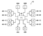
- FIG. 2 is a block diagram showing a control system of the corner grinding apparatus shown in FIG.
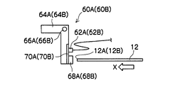
- FIG. 3A is a side view showing a state of the sensor immediately before the glass plate comes into contact with the sensor.
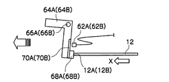
- FIG. 3B is a side view showing the state of the sensor immediately after the glass plate comes into contact with the sensor.
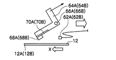
- FIG. 3C is a side view showing a state where the sensor returns to the stop position together with the grindstone carrier.
- FIG. 4 is a schematic plan view showing the operation of the grindstone carrier when the glass plate is conveyed while being inclined.
- FIG. 5 is a schematic plan view showing the operation of the grindstone carrier when the glass plate is conveyed while being tilted.
- FIG. 6 is an explanatory view of grinding a corner portion of a glass plate conveyed while being inclined with a grindstone.
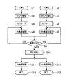
- FIG. 7 is a flowchart showing the operation of the corner grinding apparatus of the
- FIG. 1 is a plan view of a corner grinding apparatus 10 for a glass plate according to an embodiment
- FIG. 2 is a block diagram showing a control system of the corner grinding apparatus 10.
- the X direction shown in FIG. 1 has shown the conveyance direction which conveys the glass plate 12 to a horizontal direction
- the Y direction has shown the direction orthogonal to X direction on a horizontal surface.
- the glass plate 12 is exemplified by a glass substrate for FPD (Flat Panel Display) used for liquid crystal, plasma, etc., but is not limited to this.
- FPD Full Panel Display
- the corner grinding apparatus 10 has a glass plate conveying means 14 for conveying the glass plate 12 in the X direction.
- a grindstone conveying table (first grindstone conveying table) 18A is arranged on one side of the conveying path 16 of the glass plate 12 by the glass plate conveying means 14, and a grindstone conveying table (second wheel) is arranged on the other side of the conveying path 16.
- the grindstone carrier) 18B is disposed.
- the glass plate conveying means 14 has a pair of upper and lower endless conveying belts 20A provided on one side of the conveying path 16, and a pair of upper and lower endless conveying belts 20B provided on the other side of the conveying path 16. ing.
- the glass plate 12 is transported in the X direction in a state where the two opposite sides are sandwiched between a pair of upper and lower transport belts 20A and 20B. Note that the speeds of both of the conveyor belts 20A and 20B are set to the same speed by the motor 22, but a minute speed difference may occur due to a difference in elongation due to aging of the conveyor belts 20A and 20B. This difference in speed contributes to the cause of the inclined conveyance of the glass plate 12.
- a positioning device 24 that determines the conveying posture of the glass plate 12 is installed at a position adjacent to the corner grinding apparatus 10 on the upstream side of the conveying path 16.
- the positioning device 24 includes a conveyor belt 26, a positioning belt 28, and a pressing device 30.
- the conveyor belt 26 is moved around by the driving force of the motor 32 and conveys the glass plate 12 placed on the conveyor belt 26 in the X direction.
- the pressing device 30 includes a cylinder 34 and pins 36, 36.
- the piston 38 of the cylinder 34 is extended to bring the pins 36, 36 into contact with one side of the glass plate 12.
- the other side is pressed against the positioning belt 28.
- the glass plate 12 is positioned on the upstream side of the conveyance path 16.
- the positioned glass plate 12 is carried into the corner grinding apparatus 10 by the circular movement of the conveyor belt 26.
- the grindstone transport table 18A is moved in the X direction by a motor (servo motor or stepping motor: first grindstone transport table moving means) 40A and a feed device (not shown).
- the grindstone transport table 18B is moved in the X direction by a motor (servo motor or stepping motor: second grindstone transport table moving means) 40B and a feed device (not shown).
- the CPU (control means, speed difference adjusting means) 42 shown in FIG. 2 is operated by the motor 40A at the start of movement, the movement speed, the movement stop, and the return movement operation to the movement start position of each of the grindstone carriages 18A and 18B. , 40B are independently controlled. This control method will be described later.
- the grindstone carrier 18A there are a grindstone (first grindstone) 44A for grinding the corner (first corner) 12A of the glass plate 12, and a grindstone 44C for grinding the corner (first corner) 12C. It is mounted freely.
- the grindstone carrier 18B includes a grindstone (second grindstone) 44B for grinding the corner (second corner) 12B of the glass plate 12, and a grindstone for grinding the corner (second corner) 12D. 44D is movably mounted.
- the grindstones 44A to 44D are each configured in a disk shape and are driven to rotate by a motor (not shown).
- a drive means (first grindstone drive means) 46A for moving the grindstone 44A in the direction of processing the orientation flat at the corner 12A is a motor (first drive section) 48 for moving the grindstone 44A in a direction parallel to the X direction.
- the motor 48-1A is driven, the table 52A is moved in the X direction by the feeding device 50A. Since the motor 48-2A and the grindstone 44A are mounted on the table 52A, the grindstone 44A moves in the X direction. Further, when the motor 48-2A is driven, the grindstone 44A is moved in the Y direction by the feeding device 54A.
- the grindstone 44A is moved in the X direction by the motor 48-1A, the Y direction by the motor 48-2A, and the direction in which the X direction and the Y direction are combined. Further, the movement direction of the grindstone 44A, the start of movement, the movement speed, the movement stop, and the return movement operation to the movement start position are controlled by the CPU 42 shown in FIG. 2 individually for the motors 48-1A and 48-2A. Is executed.
- a drive means (second grindstone drive means) 46B for moving the grindstone 44B in the direction of processing the orientation flat at the corner 12B is a motor (first drive section) 48 for moving the grindstone 44B in a direction parallel to the X direction. -1B and a motor (second drive unit) 48-2B for moving the grindstone 44B in the Y direction.
- the motor 48-1B is driven, the table 52B is moved in the X direction by the feeding device 50B. Since the motor 48-2B and the grindstone 44B are mounted on the table 52B, the grindstone 44B moves in the X direction.
- the motor 48-2B is driven, the grindstone 44B is moved in the Y direction by the feeding device 54B.
- the grindstone 44B is moved in the X direction by the motor 48-1B, the Y direction by the motor 48-2B, and the direction in which the X direction and the Y direction are combined. Further, the movement direction of the grindstone 44B, the start of movement, the movement speed, the movement stop, and the return movement operation to the movement start position are controlled by the CPU 42 shown in FIG. 2 individually for the motors 48-1B and 48-2B. Is executed.
- a drive means (first grindstone drive means) 46C for moving the grindstone 44C in the direction of processing the orientation flat at the corner 12C is a motor (first drive section) 48 for moving the grindstone 44C in a direction parallel to the X direction. -1C and a motor (second drive unit) 48-2C for moving the grindstone 44C in the Y direction.
- the motor 48-1C is driven, the table 52C is moved in the X direction by the feeding device 50C. Since the motor 48-2C and the grindstone 44C are mounted on the table 52C, the grindstone 44C moves in the X direction.
- the motor 48-2C is driven, the grindstone 44C is moved in the Y direction by the feeding device 54C.
- the grindstone 44C is moved in the X direction by the motor 48-1C, the Y direction by the motor 48-2C, and the direction in which the X direction and the Y direction are combined. Further, the movement direction of the grindstone 44C, the start of movement, the movement speed, the movement stop, and the return movement operation to the movement start position are controlled by the CPU 42 shown in FIG. 2 individually for the motors 48-1C and 48-2C. Is executed.
- a drive means (second grindstone drive means) 46D for moving the grindstone 44D in the direction of processing the orientation flat at the corner 12D is a motor (first drive section) 48 for moving the grindstone 44D in a direction parallel to the X direction. -1D and a motor (second drive unit) 48-2D for moving the grindstone 44D in the Y direction.
- the motor 48-1D is driven, the table 52D is moved in the X direction by the feeding device 50D. Since the motor 48-2D and the grindstone 44D are mounted on the table 52D, the grindstone 44D moves in the X direction.
- the motor 48-2D is driven, the grindstone 44D is moved in the Y direction by the feeding device 54D.
- the grindstone 44D is moved in the X direction by the motor 48-1D, the Y direction by the motor 48-2D, and the direction in which the X direction and the Y direction are combined.
- the movement direction of the grindstone 44D, the movement start, the movement speed, the movement stop, and the return operation to the movement start position are controlled by the CPU 42 shown in FIG. 2 individually for the motors 48-1D and 48-2D. It is executed by.
- the corner grinding apparatus 10 of the embodiment has a sensor (first detection means) 60A for detecting the corner 12A of the glass plate 12 and a sensor (second detection means) 60B for detecting the corner 12B.
- the sensors 60A and 60B are arranged on a single line orthogonal to the X direction at the movement start positions of the grindstone transport bases 18A and 18B. Although it is most preferable to detect the corner 12A of the glass plate 12 with the sensor 60A and detect the corner 12B with the sensor 60B, the positional relationship between the sensor 60A and the grindstone 44A and the positional relationship between the sensor 60B and the grindstone 44B.
- the vicinity of the corner 12A may be detected by the sensor 60A, and the vicinity of the corner 12B may be detected by the sensor 60B.
- the vicinity portion exists on the side portion on the leading side in the conveyance direction of the glass plate 12.
- Sensors 60A and 60B have the same configuration, and include a distance sensor 62A (62B) and an L-shaped arm 64A (64B) as shown in FIGS. 3A, 3B and 3C.
- the arm 64A (64B) is swingably connected to the grindstone carrier 18A (18B) shown in FIG. 1 via a shaft 66A (66B) arranged in the horizontal direction. Further, the arm 64A (64B) is irradiated with light from the light source of the distance damper 62A (62B) and the resin damper 68A (68B) with which the corner 12A (12B) of the conveyed glass plate 12 contacts. Is attached to the light receiving portion of the distance sensor 62A (62B). Note that the configuration of the distance sensors 62A and 62B is well known, and therefore the description thereof is omitted here.
- the distance sensor 62A (62B) is fixed to the grindstone carrier 18A (18B) and moves together with the grindstone carrier 18A (18B).
- the distance information output from the distance sensor 62A (62B) is output to the CPU 42 in FIG.
- the distance sensor 62A (62B) is in contact with the reflecting portion 70A (70B) in the state of FIG. 3A before the corner portion 12A (12B) of the glass plate 12 contacts the damper 68A (68B). Therefore, information indicating that the distance is zero is output from the distance sensor 62A (62B) to the CPU.
- the distance sensor 62A (62B) is separated from the reflecting portion 70A (70B) in the state of FIG.
- the distance sensor 62A (62B) outputs information indicating the separated distance to the CPU.
- CPU42 controls motor 40A, 40B based on the said information output from distance sensor 62A (62B). This control method will be described later.
- the initial stage in the Y direction of the grindstones 44A-44D sets the position. That is, the motors 48-2A to 48-2D of the grindstones 44A to 44D are driven to set initial positions of the grindstones 44A to 44D in the Y direction.
- initial positions of the grindstones 44A to 44D in the X direction are set.
- the motors 48-1A to 48-1D of the grindstones 44A to 44D are driven to set the initial positions of the grindstones 44A to 44D in the X direction.
- the grindstones 44A to 44D stand by at a grinding start position (a position indicated by a solid line in FIG. 6) where the corners 12A to 12D are ground in the XY horizontal plane.
- the glass plate 12 shown in FIGS. 4 to 6 shows the inclination of the glass plate exaggerated, and the movement trajectories of the grindstones 44A to 44D are shown to be different so as to correspond to the inclination of the glass plate 12.
- the inclination angle of the glass plate 12 is very small, and the movement trajectories of the grindstones 44A to 44D are the same.
- the CPU 42 controls the rotation speed of the motor 40B so that the distance information output from the distance sensor 62B is constant.
- the corner 12A of the glass plate 12 comes into contact with the sensor 60A as shown in FIG. For this reason, the grindstone carrier 18A starts moving in the X direction (S6, 7, 8 in FIG. 7).
- the CPU 42 controls the rotation speed of the motor 40A so that the distance information output from the distance sensor 62A is constant.
- the CPU 42 controls the driving means 46A to 46D to move the grindstones 44A to 44D from the solid line position of FIG. S10 in FIG. Thereby, the orientation flats are processed in the corners 12A to 12D of the glass plate 12. Thereafter, the CPU 42 rotates the motors 40A and 40B in the direction opposite to the previous direction to transfer the grindstone transport tables 18A and 18B in the direction opposite to the transport direction of the glass plate 12, and the grindstone transport tables 18A and 18B are stopped. When returning to the position, the motors 40A and 40B are stopped (S11 in FIG. 7). Thereby, the process of the orientation flat in the one glass plate 12 is complete
- the movement position of the grindstone carrier 18 ⁇ / b> A can be individually controlled according to the conveyance position of the corner 12 ⁇ / b> A of the glass plate 12, and the position of the corner 12 ⁇ / b> B of the glass plate 12 can be controlled. Accordingly, the movement position of the grindstone carrier 18B can be individually controlled.
- the grindstone 44 ⁇ / b> A processes the regular position of the corner 12 ⁇ / b> A of the glass plate 12, and the grindstone 44 ⁇ / b> B. Since the regular position of the corner 12B of the glass plate 12 is processed, the dimensional processing accuracy of the orientation flat processed into the corners 12A and 12B of the glass plate 12 is improved. The same applies to the corners 12B and 12D.
- the grindstone 44A (the same as the other grindstones 44B to 44D) can be moved in the X direction by the motor 48-1A, and can be moved in the Y direction by the motor 48-2A. Therefore, the initial position of the grindstone 44 ⁇ / b> A (orientation flat grinding start position) can be easily set according to the size of the glass plate 12.
- the movement speed in the X direction by the motor 48-1A and the movement speed in the Y direction by the motor 48-2A are independently controlled by the CPU 42, so that both speeds are made the same speed or a difference in speed is given. Since the movement trajectory can be changed, the shape of the orientation flat can be changed without changing the drive unit of the grindstone.
Landscapes
- Engineering & Computer Science (AREA)
- Mechanical Engineering (AREA)
- Chemical & Material Sciences (AREA)
- Ceramic Engineering (AREA)
- Inorganic Chemistry (AREA)
- Grinding And Polishing Of Tertiary Curved Surfaces And Surfaces With Complex Shapes (AREA)
- Constituent Portions Of Griding Lathes, Driving, Sensing And Control (AREA)
Abstract
Description
本出願は、2011年2月1日出願の日本特許出願2011-020052に基づくものであり、その内容はここに参照として取り込まれる。
Claims (6)
- ガラス板を水平方向に搬送するガラス板搬送工程と、
前記ガラス板の搬送路の一方側に配置されるとともに第1の砥石が移動自在に搭載された第1の砥石搬送台、及び該ガラス板の搬送路の他方側に配置されるとともに第2の砥石が移動自在に搭載された第2の砥石搬送台をガラス板の搬送方向にガラス板とは独立して移動させる砥石搬送台移動工程と、
前記第1の砥石搬送台、及び前記第2の砥石搬送台とガラス板との間の搬送速度差を無くす速度差調整工程と、
前記搬送速度差を無くした状態で前記第1の砥石搬送台の前記第1の砥石を、前記ガラス板の第1の隅部を研削する方向に移動するとともに、前記第2の砥石搬送台の前記第2の砥石を、ガラス板の第2の隅部を研削する方向に移動してガラス板の前記第1の隅部、及び前記第2の隅部を研削する研削工程と、
を備え、前記ガラス板搬送工程と前記砥石搬送台移動工程との間に、
前記ガラス板の前記第1の隅部を第1の検知手段によって検知するとともに、前記第2の隅部を第2の検知手段によって検知する隅部検知工程と、
前記第1の検知手段によって前記第1の隅部を検知した際に、前記第1の砥石搬送台を停止位置から移動させるとともに、前記第2の検知手段によって前記第2の隅部を検知した際に、前記第2の砥石搬送台を停止位置から移動させる移動開始時期制御工程と、
を有するガラス板の隅部研削加工方法。 - 前記砥石を平面視において、前記ガラス板の搬送方向に平行な第1の方向に移動させる第1の駆動部、及び前記第1の方向に対して直交する第2の方向に移動させる第2の駆動部を備え、
前記研削工程において前記砥石は、前記第1の方向と前記第2の方向とを合成した方向に移動される請求項1に記載のガラス板の隅部研削加工方法。 - 前記研削工程において、前記第1の駆動部による前記砥石の前記第1の方向への移動速度、及び前記第2の駆動部による前記砥石の前記第2の方向への移動速度が、それぞれ独立して制御されている請求項2に記載のガラス板の隅部研削加工方法。
- ガラス板を水平方向に搬送するガラス板搬送手段と、
前記ガラス板の搬送路の一方側に配置されるともにガラス板の第1の隅部を研削する第1の砥石が移動自在に搭載された第1の砥石搬送台と、
前記ガラス板の搬送路の他方側に配置されるともにガラス板の第2の隅部を研削する第2の砥石が移動自在に搭載された第2の砥石搬送台と、
前記第1の砥石搬送台をガラス板の搬送方向にガラス板とは独立して移動させる第1の砥石搬送台移動手段と、
前記第2の砥石搬送台をガラス板の搬送方向にガラス板とは独立して移動させる第2の砥石搬送台移動手段と、
前記ガラス板の前記第1の隅部を検知する第1の検知手段と、
前記ガラス板の前記第2の隅部を検知する第2の検知手段と、
前記第1の検知手段によって前記第1の隅部を検知した際に、前記第1の砥石搬送台移動手段を制御して前記第1の砥石搬送台を停止位置から移動させるとともに、前記第2の検知手段によって前記第2の隅部を検知した際に、前記第2の砥石搬送台移動手段を制御して前記第2の砥石搬送台を停止位置から移動させる制御手段と、
前記第1の砥石搬送台移動手段、及び前記第2の砥石搬送台移動手段を制御して、前記第1の砥石搬送台、及び前記第2の砥石搬送台と前記ガラス板との間の搬送速度差を無くす速度差調整手段と、
前記搬送速度差を無くした状態で前記第1の砥石搬送台の前記第1の砥石を、前記ガラス板の第1の隅部を研削する方向に移動させてガラス板の前記第1の隅部を研削する第1の砥石駆動手段と、
前記搬送速度差を無くした状態で前記第2の砥石搬送台の前記第2の砥石を、ガラス板の第2の隅部を研削する方向に移動させてガラス板の前記第2の隅部を研削する第2の砥石駆動手段と、
を備えたガラス板の隅部研削加工装置。 - 前記第1の砥石駆動手段、及び前記第2の砥石駆動手段は、平面視において前記砥石を前記ガラス板の搬送方向に平行な第1の方向に移動させる第1の駆動部と、前記第1の方向に対して直交する第2の方向に移動させる第2の駆動部とからなる請求項4に記載のガラス板の隅部研削加工装置。
- 前記第1の駆動部による前記砥石の前記第1の方向への移動速度、及び前記第2の駆動部による前記砥石の前記第2の方向への移動速度が、前記制御手段によってそれぞれ独立して制御されている請求項5に記載のガラス板の隅部研削加工装置。
Priority Applications (3)
| Application Number | Priority Date | Filing Date | Title |
|---|---|---|---|
| KR1020137020420A KR20140007370A (ko) | 2011-02-01 | 2012-01-16 | 유리판의 코너부 연삭 가공 방법 및 가공 장치 |
| JP2012555781A JPWO2012105306A1 (ja) | 2011-02-01 | 2012-01-16 | ガラス板の隅部研削加工方法及び加工装置 |
| CN201280007230XA CN103347650A (zh) | 2011-02-01 | 2012-01-16 | 玻璃板的角部磨削加工方法及加工装置 |
Applications Claiming Priority (2)
| Application Number | Priority Date | Filing Date | Title |
|---|---|---|---|
| JP2011-020052 | 2011-02-01 | ||
| JP2011020052 | 2011-02-01 |
Publications (1)
| Publication Number | Publication Date |
|---|---|
| WO2012105306A1 true WO2012105306A1 (ja) | 2012-08-09 |
Family
ID=46602526
Family Applications (1)
| Application Number | Title | Priority Date | Filing Date |
|---|---|---|---|
| PCT/JP2012/050750 Ceased WO2012105306A1 (ja) | 2011-02-01 | 2012-01-16 | ガラス板の隅部研削加工方法及び加工装置 |
Country Status (5)
| Country | Link |
|---|---|
| JP (1) | JPWO2012105306A1 (ja) |
| KR (1) | KR20140007370A (ja) |
| CN (1) | CN103347650A (ja) |
| TW (1) | TW201242718A (ja) |
| WO (1) | WO2012105306A1 (ja) |
Cited By (4)
| Publication number | Priority date | Publication date | Assignee | Title |
|---|---|---|---|---|
| KR101476640B1 (ko) * | 2014-10-01 | 2014-12-29 | (주) 세명유리 | 판유리의 사각 모서리 라운딩 가공용 연마장치 |
| WO2017094462A1 (ja) * | 2015-12-03 | 2017-06-08 | 日本電気硝子株式会社 | 板ガラスの製造方法及び製造装置 |
| KR20210154145A (ko) | 2019-04-19 | 2021-12-20 | 니폰 덴키 가라스 가부시키가이샤 | 유리판의 제조 장치 및 유리판의 제조 방법 |
| CN113953927A (zh) * | 2021-11-25 | 2022-01-21 | 广东辰钢智能科技有限公司 | 一种用于双边磨边机的伺服追踪式玻璃安全角加工装置 |
Families Citing this family (1)
| Publication number | Priority date | Publication date | Assignee | Title |
|---|---|---|---|---|
| CN106516740B (zh) * | 2016-10-27 | 2018-10-19 | 信义玻璃(天津)有限公司 | 一种自调节双边自动磨边系统 |
Citations (2)
| Publication number | Priority date | Publication date | Assignee | Title |
|---|---|---|---|---|
| JP2003171134A (ja) * | 2001-12-03 | 2003-06-17 | Bando Kiko Co Ltd | ガラス板の隅取方法及びその装置 |
| JP2003285252A (ja) * | 2002-03-27 | 2003-10-07 | Fukuyama Tekkosho:Kk | コーナカット装置 |
Family Cites Families (4)
| Publication number | Priority date | Publication date | Assignee | Title |
|---|---|---|---|---|
| AU2002344609A1 (en) * | 2002-10-30 | 2004-05-25 | Bando Kiko Co., Ltd. | Glass pane machining device |
| JP5051613B2 (ja) * | 2007-03-02 | 2012-10-17 | 旭硝子株式会社 | ガラス板の端面研削装置 |
| JP5625225B2 (ja) * | 2008-02-21 | 2014-11-19 | 坂東機工株式会社 | ガラス板の加工機械 |
| CN201380415Y (zh) * | 2009-03-18 | 2010-01-13 | 广州亚陆控制系统有限公司 | 玻璃导角磨削系统 |
-
2012
- 2012-01-16 JP JP2012555781A patent/JPWO2012105306A1/ja not_active Withdrawn
- 2012-01-16 WO PCT/JP2012/050750 patent/WO2012105306A1/ja not_active Ceased
- 2012-01-16 CN CN201280007230XA patent/CN103347650A/zh active Pending
- 2012-01-16 KR KR1020137020420A patent/KR20140007370A/ko not_active Withdrawn
- 2012-02-01 TW TW101103279A patent/TW201242718A/zh unknown
Patent Citations (2)
| Publication number | Priority date | Publication date | Assignee | Title |
|---|---|---|---|---|
| JP2003171134A (ja) * | 2001-12-03 | 2003-06-17 | Bando Kiko Co Ltd | ガラス板の隅取方法及びその装置 |
| JP2003285252A (ja) * | 2002-03-27 | 2003-10-07 | Fukuyama Tekkosho:Kk | コーナカット装置 |
Cited By (7)
| Publication number | Priority date | Publication date | Assignee | Title |
|---|---|---|---|---|
| KR101476640B1 (ko) * | 2014-10-01 | 2014-12-29 | (주) 세명유리 | 판유리의 사각 모서리 라운딩 가공용 연마장치 |
| WO2017094462A1 (ja) * | 2015-12-03 | 2017-06-08 | 日本電気硝子株式会社 | 板ガラスの製造方法及び製造装置 |
| CN108025415A (zh) * | 2015-12-03 | 2018-05-11 | 日本电气硝子株式会社 | 板状玻璃的制造方法以及制造装置 |
| KR20180091806A (ko) * | 2015-12-03 | 2018-08-16 | 니폰 덴키 가라스 가부시키가이샤 | 판유리의 제조 방법 및 제조 장치 |
| KR102493145B1 (ko) | 2015-12-03 | 2023-01-30 | 니폰 덴키 가라스 가부시키가이샤 | 판유리의 제조 방법 및 제조 장치 |
| KR20210154145A (ko) | 2019-04-19 | 2021-12-20 | 니폰 덴키 가라스 가부시키가이샤 | 유리판의 제조 장치 및 유리판의 제조 방법 |
| CN113953927A (zh) * | 2021-11-25 | 2022-01-21 | 广东辰钢智能科技有限公司 | 一种用于双边磨边机的伺服追踪式玻璃安全角加工装置 |
Also Published As
| Publication number | Publication date |
|---|---|
| TW201242718A (en) | 2012-11-01 |
| CN103347650A (zh) | 2013-10-09 |
| JPWO2012105306A1 (ja) | 2014-07-03 |
| KR20140007370A (ko) | 2014-01-17 |
Similar Documents
| Publication | Publication Date | Title |
|---|---|---|
| JP4887630B2 (ja) | ガラス基板の位置決め装置及び端面研削装置 | |
| KR20150140561A (ko) | 판재의 둘레가장자리 가공장치 및 곡면판의 둘레가장자리 가공방법 | |
| TW201117920A (en) | Method of processing glass substrate and device thereof | |
| JPWO2012105306A1 (ja) | ガラス板の隅部研削加工方法及び加工装置 | |
| JP2008213090A (ja) | ガラス板の端面研削装置 | |
| CN107265839B (zh) | 划片设备 | |
| JP5397840B2 (ja) | ガラス基板の位置決め装置、位置決め方法、端面研削装置及び端面研削方法 | |
| CN107151091B (zh) | 划片设备 | |
| JP2011168444A (ja) | ガラス板加工装置及びその加工方法 | |
| CN105579201A (zh) | 运送装置以及真空装置 | |
| JP2002052449A (ja) | ガラス板の加工方法及びその装置 | |
| WO2018180651A1 (ja) | ガラス板の製造方法及びその製造装置 | |
| TWI572570B (zh) | 具有雙控制器之玻璃面板切割裝置 | |
| KR102341797B1 (ko) | 단재 제거 유닛 | |
| CN107265838B (zh) | 划片设备 | |
| TW202000615A (zh) | 基板加工裝置之基板定位機構及基板定位方法 | |
| JP4854337B2 (ja) | 板材の加工装置とそれを備えた加工設備 | |
| JP2836313B2 (ja) | 板硝子のコーナカット方法及びその装置 | |
| CN109553287B (zh) | 划片设备及划片方法 | |
| TWI499871B (zh) | Exposure apparatus and exposure method | |
| CN102617028A (zh) | 加工管理系统 | |
| KR20160113348A (ko) | 기판 이송 유닛 및 이를 포함하는 기판 이송 장치 | |
| JP2001179586A (ja) | 板ガラスのコーナカット方法及びその装置 | |
| JP2001239443A (ja) | ガラス板を隅取りする方法及びその装置 | |
| KR20190018080A (ko) | 스크라이빙 장치 |
Legal Events
| Date | Code | Title | Description |
|---|---|---|---|
| 121 | Ep: the epo has been informed by wipo that ep was designated in this application |
Ref document number: 12741923 Country of ref document: EP Kind code of ref document: A1 |
|
| ENP | Entry into the national phase |
Ref document number: 2012555781 Country of ref document: JP Kind code of ref document: A |
|
| ENP | Entry into the national phase |
Ref document number: 20137020420 Country of ref document: KR Kind code of ref document: A |
|
| NENP | Non-entry into the national phase |
Ref country code: DE |
|
| 122 | Ep: pct application non-entry in european phase |
Ref document number: 12741923 Country of ref document: EP Kind code of ref document: A1 |