WO2012105290A1 - 内燃機関の冷却構造 - Google Patents
内燃機関の冷却構造 Download PDFInfo
- Publication number
- WO2012105290A1 WO2012105290A1 PCT/JP2012/050544 JP2012050544W WO2012105290A1 WO 2012105290 A1 WO2012105290 A1 WO 2012105290A1 JP 2012050544 W JP2012050544 W JP 2012050544W WO 2012105290 A1 WO2012105290 A1 WO 2012105290A1
- Authority
- WO
- WIPO (PCT)
- Prior art keywords
- cylinder liner
- cylinder
- cooling
- internal combustion
- combustion engine
- Prior art date
- Legal status (The legal status is an assumption and is not a legal conclusion. Google has not performed a legal analysis and makes no representation as to the accuracy of the status listed.)
- Ceased
Links
Images






Classifications
-
- F—MECHANICAL ENGINEERING; LIGHTING; HEATING; WEAPONS; BLASTING
- F02—COMBUSTION ENGINES; HOT-GAS OR COMBUSTION-PRODUCT ENGINE PLANTS
- F02F—CYLINDERS, PISTONS OR CASINGS, FOR COMBUSTION ENGINES; ARRANGEMENTS OF SEALINGS IN COMBUSTION ENGINES
- F02F1/00—Cylinders; Cylinder heads
- F02F1/02—Cylinders; Cylinder heads having cooling means
- F02F1/10—Cylinders; Cylinder heads having cooling means for liquid cooling
-
- F—MECHANICAL ENGINEERING; LIGHTING; HEATING; WEAPONS; BLASTING
- F02—COMBUSTION ENGINES; HOT-GAS OR COMBUSTION-PRODUCT ENGINE PLANTS
- F02F—CYLINDERS, PISTONS OR CASINGS, FOR COMBUSTION ENGINES; ARRANGEMENTS OF SEALINGS IN COMBUSTION ENGINES
- F02F1/00—Cylinders; Cylinder heads
- F02F1/02—Cylinders; Cylinder heads having cooling means
- F02F1/10—Cylinders; Cylinder heads having cooling means for liquid cooling
- F02F1/14—Cylinders with means for directing, guiding or distributing liquid stream
-
- F—MECHANICAL ENGINEERING; LIGHTING; HEATING; WEAPONS; BLASTING
- F01—MACHINES OR ENGINES IN GENERAL; ENGINE PLANTS IN GENERAL; STEAM ENGINES
- F01P—COOLING OF MACHINES OR ENGINES IN GENERAL; COOLING OF INTERNAL-COMBUSTION ENGINES
- F01P3/00—Liquid cooling
- F01P3/02—Arrangements for cooling cylinders or cylinder heads
-
- F—MECHANICAL ENGINEERING; LIGHTING; HEATING; WEAPONS; BLASTING
- F02—COMBUSTION ENGINES; HOT-GAS OR COMBUSTION-PRODUCT ENGINE PLANTS
- F02F—CYLINDERS, PISTONS OR CASINGS, FOR COMBUSTION ENGINES; ARRANGEMENTS OF SEALINGS IN COMBUSTION ENGINES
- F02F1/00—Cylinders; Cylinder heads
- F02F1/02—Cylinders; Cylinder heads having cooling means
- F02F1/10—Cylinders; Cylinder heads having cooling means for liquid cooling
- F02F1/16—Cylinder liners of wet type
-
- F—MECHANICAL ENGINEERING; LIGHTING; HEATING; WEAPONS; BLASTING
- F01—MACHINES OR ENGINES IN GENERAL; ENGINE PLANTS IN GENERAL; STEAM ENGINES
- F01P—COOLING OF MACHINES OR ENGINES IN GENERAL; COOLING OF INTERNAL-COMBUSTION ENGINES
- F01P3/00—Liquid cooling
- F01P3/02—Arrangements for cooling cylinders or cylinder heads
- F01P2003/021—Cooling cylinders
Definitions
- the present invention relates to a cooling structure for an internal combustion engine applied to an internal combustion engine such as a marine diesel engine.
- cooling bore As a cooling structure of an internal combustion engine applied to an internal combustion engine such as a marine diesel engine, a cooling hole (hereinafter referred to as “cooling bore”) tilted with respect to a plane perpendicular to the cylinder axis inside (inside the wall). (For example, refer patent document 1).
- the compressive stress is maximized on the inner peripheral surface and the tensile stress is maximized on the outer peripheral surface, as shown in FIG.
- the shape of the cooling bore (drilling hole: drill hole) located at the uppermost outer peripheral surface in a plan view is shown in FIG. 4 and FIG. As shown in FIG. 7, it becomes elliptical and the thermal stress at the outlet peripheral edge of the cooling bore increases. Therefore, in the cylinder liner disclosed in Patent Document 1, it has been difficult to reduce the wall thickness and reduce the weight.
- the present invention has been made in view of the above circumstances, and an object of the present invention is to provide a cooling structure for an internal combustion engine that can reduce the thickness of the cylinder liner and reduce the weight.
- a cooling structure for an internal combustion engine includes a cylinder liner provided with a plurality of first cooling bores that are opened obliquely upward from the outer peripheral surface into the wall, and the outer peripheral surface into the wall.
- a cooling system for an internal combustion engine comprising: a plurality of second cooling bores that are opened obliquely upward, and a cylinder cover that is disposed on the cylinder liner and closes an opening located above the cylinder liner.
- the cylinder liner and the cylinder cover are fitted to the cylinder liner and the outer peripheral surface of the cylinder cover across the cylinder liner and the cylinder cover at a joint portion between the cylinder liner and the cylinder cover, and the cylinder liner and A cooling water passage is formed between the cylinder cover and the outer peripheral surface of the cylinder cover, and the radial direction of the cylinder liner during operation of the internal combustion engine. It inhibits the spread of outward and is equipped with a ring-shaped reinforcing fittings.
- the outward expansion of the cylinder liner in the radial direction during operation of the internal combustion engine is suppressed (restrained) by the reinforcing hardware.
- the thickness of a cylinder liner can be reduced and the outer diameter of a cylinder liner, a cylinder cover, and a reinforcement hardware can be reduced and weight reduction can be achieved.
- the outlet of the first cooling bore is provided at a central portion in the plate thickness direction of the cylinder liner.
- the outlet (ie, the mouth) of the first cooling bore is the central portion in the plate thickness direction of the cylinder liner, that is, the stress 0 (zero) point (both compressive stress and tensile stress act).
- the outlet of the first cooling bore is directed radially inward from the outer peripheral surface of the upper end portion of the cylinder liner facing the inner peripheral surface of the lower half portion of the reinforcement metal. It is more preferable that it is provided on an inclined surface that is engraved and forms a circumferential groove.
- the outlet of the first cooling bore is provided on the inclined surface forming the circumferential groove so that the shape of the plan view thereof is close to a circular shape.
- the thickness of the cylinder liner can be further reduced, the outer diameter of the cylinder liner, cylinder cover and reinforcement hardware can be reduced and the weight can be reduced, and the stress concentration at the outlet of the first cooling bore can be further reduced. It can be mitigated (reduced).
- the first cooling bore and the inclined surface are provided so that a longitudinal axis of the first cooling bore is orthogonal to the inclined surface. More preferably.
- the outlet of the first cooling bore is provided on the inclined surface forming the circumferential groove so that the planar view shape thereof is circular.
- the thickness of the cylinder liner can be further reduced, the outer diameter of the cylinder liner, cylinder cover and reinforcement hardware can be reduced and the weight can be reduced, and the stress concentration at the outlet of the first cooling bore can be further reduced. It can be mitigated (reduced).
- the reinforcing hardware is made of a metal material having an elastic coefficient larger than that of the cylinder liner and the cylinder cover.
- a (predetermined) gap is ensured between the inner peripheral surface of the lower half of the reinforcing metal and the outer peripheral surface of the cylinder liner when the internal combustion engine is stopped (in a cold state).
- a (predetermined) gap is ensured between the inner peripheral surface of the upper half of the reinforcing hardware and the outer peripheral surface of the cylinder cover, and the inner peripheral surface of the lower half of the reinforcing hardware is in operation (in the warm state) during internal combustion engine operation.
- the outer peripheral surface of the cylinder liner is in contact with the inner peripheral surface of the upper half of the reinforcing metal and the outer peripheral surface of the cylinder cover.
- the reinforcing hardware is configured to be divided into two parts in the vertical direction on a plane including a joint surface between the cylinder liner and the cylinder cover. is there.
- the inner peripheral surface of the lower half portion of the reinforcement metal is in contact with the outer peripheral surface of the cylinder liner
- the inner peripheral surface of the upper half of the reinforcement hardware is the cylinder cover.
- the cylinder cover and the upper half of the reinforcement hardware can be removed from the cylinder liner and the lower half of the reinforcement hardware even in contact with the outer peripheral surface of the cylinder liner.
- the upper half of the cylinder cover and the reinforcing hardware and the lower half of the cylinder liner and the reinforcing hardware are divided by a plane including the joint surface between the cylinder liner and the cylinder cover.
- the lifting height of the piston in the operation can be made the same as the conventional height, and the ceiling height of the engine room can be made the same as the conventional height.
- a cylinder liner is a cylinder liner including a plurality of first cooling bores that are opened obliquely upward from the outer peripheral surface toward the inside of the wall.
- the outlet is provided in an inclined surface that is carved inwardly in the radial direction from the outer peripheral surface of the upper end portion of the cylinder liner at the center in the plate thickness direction of the cylinder liner.
- the outlet of the first cooling bore is provided on the inclined surface that forms the circumferential groove so that the shape in plan view exhibits a shape close to a circular shape.
- the thickness of the cylinder liner can be reduced, the outer diameter of the cylinder liner can be reduced and the weight can be reduced, and the stress concentration at the outlet of the first cooling bore can be reduced (reduced).
- the first cooling bore and the inclined surface are provided so that a longitudinal axis of the first cooling bore is orthogonal to the inclined surface. Further preferred.
- the outlet of the first cooling bore is provided on the inclined surface that forms the circumferential groove so that the planar view shape thereof is circular.
- the thickness of the cylinder liner can be further reduced, the outer diameter of the cylinder liner can be reduced and the weight can be reduced, and stress concentration at the outlet of the first cooling bore can be further reduced (reduced). Can do.
- An internal combustion engine includes any one of the above-described cooling structures for an internal combustion engine or any one of the above-described cylinder liners.
- the internal combustion engine according to the third aspect can reduce the overall size and weight of the engine.
- the thickness of the cylinder liner can be reduced and the weight can be reduced.
- FIG. 3 is a view taken in the direction of arrows III-III in FIG. 2. It is a figure which expands and shows the principal part of FIG.
- FIG. 5 is a VV arrow view of FIG. 4. It is the figure which looked at the lower half part internal peripheral surface of the reinforcement hardware which concerns on 2nd Embodiment of this invention from the center side of the reinforcement hardware, Comprising: It is a figure similar to FIG.
- FIG. 10 is an XX arrow view of FIG. 9.
- FIG. 10 is a view on arrow XI-XI in FIG. 9.
- FIG. 10 is a figure for demonstrating the stress which acts on the exit of the cooling bore which concerns on the past and this invention.
- FIGS. 1 to 5 are perspective views of a cylinder liner according to the present embodiment
- FIG. 2 is a cross-sectional view of a main part showing a cooling structure of an internal combustion engine according to the present embodiment
- FIG. 3 is a view taken in the direction of arrows III-III in FIG.
- FIG. 5 is an enlarged view of the main part of FIG. 2
- FIG. 5 is a view taken along the line VV of FIG.
- the cylinder liner, cylinder cover, and reinforcing hardware according to the present invention are applied to an internal combustion engine such as a marine diesel engine, and a piston (not shown) is disposed therein, and the piston is disposed on the inner peripheral surface thereof. Will slide along.
- the reinforcing hardware 10 according to the present embodiment straddles both the cylinder liner 20 and the cylinder cover 40 at the joint portion between the cylinder liner 20 and the cylinder cover 40.
- the cooling water passage (cooling water flow passage) 11 is formed between the outer periphery of the cylinder liner 20 and the cylinder cover 40 by being fitted to the outer peripheral surfaces of the cylinder liner 20 and the cylinder cover 40, and during operation of the internal combustion engine (temperature state).
- This is a ring-shaped (annular) member that suppresses (restrains) the cylinder liner 20 from spreading outward in the radial direction.
- the cooling water passage 11 has a longitudinal axis (center axis) parallel to the cylinder axis (longitudinal axis of the cylinder liner 20) on the inner peripheral surface 12 of the lower half of the reinforcing hardware 10, and the circumference of the reinforcing metal 10
- a plurality of vertical grooves 13 provided at regular intervals along the direction, and the upper half inner peripheral surface 14 of the reinforcing hardware 10 are orthogonal to the vertical grooves 13 and along the circumferential direction of the reinforcing hardware 10. It is formed by a single (first) circumferential groove 15 provided.
- the longitudinal groove 13 is a groove carved (excavated) radially outward from the lower half inner peripheral surface 12 of the reinforcing hardware 10, and the circumferential groove 15 extends from the upper half inner peripheral surface 14 of the reinforcing hardware 10. It is a groove carved (drilled down) radially outward.
- the upper end part (one end part) of the cylinder liner 20 which concerns on this embodiment is provided with the enlarged diameter part (projection part) 21 which protrudes toward a radial direction outer side along the circumferential direction.
- the enlarged-diameter portion 21 includes a (first) inclined surface 22 whose outer diameter gradually increases from the lower end (other end) side of the cylinder liner 20 toward the upper end (one end) side, and a cylinder.
- the liner 20 is formed so as to be parallel to a (first) side surface (outer peripheral surface) 23 having a constant outer diameter from the lower end side to the upper end side and a plane perpendicular to the cylinder axis.
- An upper surface (end surface) 24 is formed.
- the inclined surface 22 and the side surface 23 are formed so as to be continuous, and the side surface 23 and the upper surface 24 are formed so as to be continuous.
- a (second) side surface (outer peripheral surface) 25 having a (substantially) constant outer diameter from the lower end side to the upper end side of the cylinder liner 20.
- the outer diameter of the cylinder liner 20 gradually decreases from the lower end (other end) side to the upper end (one end) side of the side surface 25.
- a (second) inclined surface 26 is provided.
- the upper surface 24 and the side surface 25 are formed so as to be continuous, and the side surface 25 and the inclined surface 26 are formed so as to be continuous.
- the cylinder liner 20 is provided with a plurality of (first) cooling bores 30 (14 in this embodiment) along the circumferential direction.
- the cooling bore 30 is a straight hole that communicates the inclined surface 22 and the inclined surface 26.
- the inlet (wood opening) 31 of the cooling bore 30 is provided on the inclined surface 22
- the outlet (wood opening) 32 of the cooling bore 30 is provided on the inclined surface 26, and the longitudinal axis of the cooling bore 30 ( The central axis) is inclined with respect to a plane perpendicular to the cylinder axis.
- a cylinder cover 40 is disposed on the cylinder liner 20, and an opening located above the cylinder liner 20 is closed (sealed).
- the cylinder cover 40 includes an upper cooling bore 41 and a lower cooling bore (second cooling bore) 42.
- the upper cooling bore 41 is provided on the outer peripheral surface of the cylinder cover 40 when a cover outer cylinder (water chamber hardware) (not shown) is fitted on the outer peripheral surface of the cylinder cover 40 located above (one side) of the reinforcing hardware 10.
- a plurality of cylinder covers 40 are provided along the circumferential direction of the cylinder cover 40.
- the longitudinal axis (center axis) of the upper cooling bore 41 is inclined with respect to a plane perpendicular to the cylinder axis.
- the lower cooling bore 42 is a circumference provided on the inner peripheral surface 14 of the upper half portion of the reinforcing hardware 10 when the cover outer cylinder is fitted to the outer peripheral surface of the cylinder cover 40 located above (one side) of the reinforcing hardware 10. It is a straight hole that communicates the groove 15 and the water chamber 43 located above (one side) the circumferential groove 15, and a plurality of holes are provided along the circumferential direction of the cylinder cover 40.
- the longitudinal axis (center axis) of the lower cooling bore 42 is inclined with respect to a plane perpendicular to the cylinder axis.
- the outer diameter gradually increases gradually from the lower end side to the upper end side of the cylinder liner 20.
- a (third) inclined surface 27 is provided, and on the upper side (one end side) of the inclined surface 27, a (third) side surface (outer peripheral surface) 28 having a (substantially) constant outer diameter is provided.
- the inclined surface 26 and the inclined surface 27 are formed so as to be continuous, and the inclined surface 27 and the side surface 28 are formed so as to be continuous. Further, the inclined surfaces 26 and 27 form a circumferential groove 29 that is carved (digged down) radially inward from the outer peripheral surface of the upper end portion of the cylinder liner 20 along the circumferential direction of the cylinder liner 20. .
- the lower surface (bottom surface) 16 of the reinforcing hardware 10 is in contact with the upper surface 24 of the enlarged diameter portion 21, and the lower half inner peripheral surface 12, the side surface 25, and the side surface 28 A (predetermined) gap is secured between them, and a (predetermined) gap is secured between the upper surface (horizontal plane) 17 facing the lower surface of the peripheral edge of the cylinder cover 40, and the inner peripheral surface 14 of the upper half thereof is the cylinder cover. 40 in contact with the outer peripheral surface, and when the internal combustion engine is operating (during warming), the lower surface 16 is in contact with the upper surface 24 of the enlarged diameter portion 21, and the lower half inner peripheral surface 12 is in contact with the side surface 25 and the side surface 28.
- a (predetermined) gap is secured between the lower surface of the peripheral edge of the cylinder cover 40 and the upper surface 17 facing the cylinder cover 40, and the upper half inner peripheral surface 14 is in contact with the outer peripheral surface of the cylinder cover 40.
- 2 and 4 indicates a (third) water chamber formed by the lower half inner peripheral surface 12 of the reinforcing hardware 10 and the inclined surfaces 26 and 27 of the cylinder liner 20.
- the expansion of the cylinder liner 20 to the outside in the radial direction during operation of the internal combustion engine is suppressed by the reinforcing hardware 10. (Restricted).
- the thickness of the cylinder liner 20 can be reduced, and the outer diameter of the cylinder liner 20, the cylinder cover 40, and the reinforcement hardware 10 can be reduced and the weight thereof can be reduced.
- the outlet 32 of the cooling bore 30 is the central portion in the plate thickness direction of the cylinder liner 20, that is, In the vicinity of a stress 0 (zero) point (a point at which neither compressive stress nor tensile stress acts) and at a place (region) where a thermal stress smaller than the thermal stress on the outermost peripheral surface acts.
- a stress 0 (zero) point a point at which neither compressive stress nor tensile stress acts
- a place (region) where a thermal stress smaller than the thermal stress on the outermost peripheral surface acts the thickness of the cylinder liner 20 can be further reduced, the outer diameter of the cylinder liner 20, the cylinder cover 40, and the reinforcing hardware 10 can be reduced, the weight can be reduced, and the stress concentration at the outlet of the cooling bore 30 can be achieved. Can be reduced (reduced).
- the outlet 32 of the cooling bore 30 is provided on the inclined surface 26 that forms the circumferential groove 29.
- the planar view shape is provided so as to exhibit a shape close to a circular shape.
- the cooling bore 30 and the inclined surface 26 are provided so that the longitudinal axis of the cooling bore 30 is orthogonal to the inclined surface 26.
- the outlet 32 of the cooling bore 30 is provided on the inclined surface 26 forming the circumferential groove 29 so that the shape in plan view thereof is circular.
- the inner peripheral surface of the lower half portion of the reinforcement hardware when the internal combustion engine is stopped (during cooling). (Predetermined) between the cylinder liner and the outer peripheral surface of the cylinder liner, and a (predetermined) clearance is secured between the upper half inner peripheral surface of the reinforcing hardware and the outer peripheral surface of the cylinder cover.
- the cylinder liner 20 is arranged such that the inner peripheral surface of the lower half of the reinforcement hardware contacts the outer peripheral surface of the cylinder liner, and the inner peripheral surface of the upper half of the reinforcement hardware contacts the outer peripheral surface of the cylinder cover.
- a metal material having an elastic modulus larger than that of the cylinder cover 40 for example, when the cylinder liner 20 and the cylinder cover 40 are made of FC250, S25C or Reinforcement hardware 10 is made of SS400.
- FC250, S25C or Reinforcement hardware 10 is made of SS400.
- FC250 flake graphite cast iron (gray cast iron) with a guaranteed tensile strength of 250 N / mm 2 or more
- S25C is a general structural carbon steel with a carbon content of 0.25%
- SS400 is 400 N / mm 2 or more. It is a general structural rolled steel with a guaranteed tensile strength.
- the outlet 32 of the cooling bore 30 is provided on the inclined surface 26 that forms the circumferential groove 29 so that the planar view shape thereof is a shape close to a circular shape. Become. Thereby, the thickness of the cylinder liner 20 can be reduced, the outer diameter of the cylinder liner 20 can be reduced and the weight thereof can be reduced, and stress concentration at the outlet 32 of the cooling bore 30 can be reduced (reduced). it can.
- the cooling bore 30 and the inclined surface 26 are provided so that the longitudinal axis of the cooling bore 30 is orthogonal to the inclined surface 26.
- the outlet 32 of the cooling bore 30 is provided on the inclined surface 26 forming the circumferential groove 29 so that the shape in plan view thereof is circular.
- the entire engine can be reduced in size and weight.
- FIG. 6 is a view of the inner peripheral surface of the lower half portion of the reinforcing hardware according to the present embodiment as viewed from the center side of the reinforcing hardware, and is the same as FIG.
- the reinforcing metal piece 50 according to the present embodiment is different from that of the first embodiment described above in that a vertical groove (oblique groove) 51 is provided instead of the vertical groove 13. Since other components are the same as those of the first embodiment described above, description of these components is omitted here.
- symbol is attached
- the longitudinal groove 51 is a groove carved from the inner peripheral surface 12 of the lower half portion of the reinforcing hardware 50 toward the outside in the radial direction, and has a longitudinal axis (center axis) as shown in FIG. There are provided a plurality of pieces that are inclined with respect to a plane perpendicular to the cylinder axis and that are provided at regular intervals along the circumferential direction of the reinforcing hardware 50.
- the passage length (flow path length) of the longitudinal groove 51 is longer than the passage length of the longitudinal groove 13 of the first embodiment described above, and the longitudinal groove 51 is formed from the cylinder liner 20. A lot of heat is transferred to the circulating cooling water, and the cooling efficiency of the cylinder liner 20 can be improved. Other functions and effects are the same as those of the above-described first embodiment, and thus description thereof is omitted here.
- FIGS. 7 is a cross-sectional view of the main part showing the cooling structure of the internal combustion engine according to the present embodiment, and is a view similar to FIG. 2, FIG. 8 is a view taken along arrow VIII-VIII in FIG. 7, and FIG. FIG. 10 is an enlarged view of the main part, FIG. 10 is a view taken along arrow XX in FIG. 9, and FIG. 11 is a view taken along arrow XI-XI in FIG.
- the reinforcing hardware 60 according to this embodiment is different from that of the first embodiment described above in that a communication hole 61 is provided instead of the vertical groove 13. Since other components are the same as those of the first embodiment described above, description of these components is omitted here.
- symbol is attached
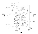
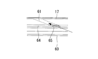
- the communication hole 61 is parallel to the circumferential groove 15 on the inner peripheral surface 12 of the lower half portion of the reinforcing hardware 60 and is provided with a single (second) circumferential groove 62 provided along the circumferential direction of the reinforcing hardware 60. These are straight holes that communicate with the upper surface 17, and a plurality of holes are provided along the circumferential direction of the reinforcing hardware 60.
- the communication hole 61 is provided such that its longitudinal axis (center axis) is inclined with respect to a plane perpendicular to the cylinder axis, and is spaced apart along the circumferential direction of the reinforcing hardware 60.
- the circumferential groove 62 is a groove carved from the inner peripheral surface 12 of the lower half portion of the reinforcing hardware 60 toward the radially outer side, and has an inner diameter from the lower end side to the upper end side of the cylinder liner 20. Is gradually (gradually) enlarged (first) inclined surface 63, and the inner diameter of the cylinder liner 20 is gradually (gradually) reduced from the lower end side toward the upper end side (second) inclination.
- the surface 64 is formed.
- the inclined surface 63 and the inclined surface 64 are formed so as to be continuous.
- An inlet (a kerf) 65 of the communication hole 61 is provided on an inclined surface 64, and a (fourth) water chamber is formed by the inclined surfaces 26 and 27 of the cylinder liner 20 and the inclined surfaces 63 and 64 of the reinforcing hardware 60. 66 is formed.
- FIG. 12 is an enlarged cross-sectional view showing a main part showing the internal combustion engine cooling structure according to the present embodiment.
- the reinforcing metal piece 70 according to the present embodiment is a plane (horizontal plane) 71 including a joint surface at the outer peripheral edge portion between the cylinder liner 20 and the cylinder cover 90, and is configured so as to be divided into two parts in the vertical direction.
- plane (horizontal plane) 71 including a joint surface at the outer peripheral edge portion between the cylinder liner 20 and the cylinder cover 90, and is configured so as to be divided into two parts in the vertical direction.
- symbol is attached
- the reinforcing hardware 70 is fitted to the outer peripheral surfaces of the cylinder liner 20 and the cylinder cover 90 across the cylinder liner 20 and the cylinder cover 90 at the joint portion between the cylinder liner 20 and the cylinder cover 90.
- a cooling water passage (cooling water passage) 72 is formed between the cylinder liner 20 and the outer peripheral surface of the cylinder cover 90, and the cylinder liner 20 spreads outward in the radial direction when the internal combustion engine is operating (during the warm state). It is a ring-shaped (annular) member that is restrained (restrained), and includes an upper half 73 and a lower half 74 that are vertically divided by a plane 71.
- the cooling water passage 72 has a longitudinal axis (center axis) inclined on the inner peripheral surface of the upper half 73 with respect to a plane parallel to the cylinder axis or perpendicular to the cylinder axis.
- a plurality of vertical grooves (or oblique grooves) 75 provided at regular intervals along the circumferential direction of the cylinder and a longitudinal axis (center axis) thereof on the inner peripheral surface of the lower half 74 is a cylinder axis.
- a plurality of vertical grooves (or slant grooves) 76 which are inclined with respect to a plane perpendicular to the cylinder axis and provided at regular intervals along the circumferential direction of the lower half 74. Is formed.
- the vertical groove 75 is a groove carved (digged down) from the inner peripheral surface of the upper half 73 toward the radial outer side, and the vertical groove 76 extends radially outward from the inner peripheral surface of the lower half 74. It is a groove carved towards (digged into).
- a recess 91 is formed along the circumferential direction.
- the recess 91 includes a (first) side surface (outer peripheral surface) 92 having a (substantially) constant outer diameter from the lower end (one end) side to the upper end (other end) side of the cylinder cover 90, and a cylinder shaft. And a lower surface (end surface) 93 formed to be parallel to a plane perpendicular to the surface.
- the side surface 92 and the lower surface 93 are formed to be continuous, and the lower surface 93 and the (second) side surface (outer peripheral surface) 94 are formed to be continuous.
- the side surface 92 is provided with one circumferential groove 95 which is parallel to the plane 71 and provided along the circumferential direction of the cylinder cover 90.
- the circumferential groove 95 is a groove carved (digged down) radially inward from the side surface 92, and its outer diameter gradually decreases gradually from the lower end side to the upper end side of the cylinder cover 90.
- a (first) inclined surface 96 having a diameter and a (second) inclined surface 97 whose inner diameter gradually increases gradually from the lower end side to the upper end side of the cylinder cover 90 are formed. Yes.
- the inclined surface 96 and the inclined surface 97 are formed to be continuous. Further, in the present embodiment, the inlet (wood end) 98 of the lower cooling bore 42 is provided on the inclined surface 97.
- the lower surface (bottom surface) 77 of the lower half portion 74 is in contact with the upper surface 24 of the enlarged diameter portion 21, and the inner peripheral surface and the side surface 25 of the lower half portion 74.
- a (predetermined) gap is ensured between the side surface 28 and a (predetermined) gap is secured between the inner peripheral surface of the upper half 73 and the side surface 92, and the upper surface 78 of the upper half 73 is recessed.
- the lower surface 79 of the upper half 73 is in contact with the lower surface 79 of the upper half 73 and the upper surface 80 of the lower half 74, and the lower surface 77 of the lower half 74 is the expanded portion during internal combustion engine operation (during warming).
- the inner peripheral surface of the lower half 74 is in contact with the outer peripheral surface of the cylinder liner 20, and the inner peripheral surface of the upper half 73 is a cylinder.
- the cylinder cover 90 and the upper half part 73 can be removed from the cylinder liner 20 and the lower half part 74 even in a state in contact with the outer peripheral surface of the cover 90.
- the upper half of the cylinder covers 90 and 73 and the cylinder liner 20 and the lower half 74 are divided by the plane 71 including the joint surface between the cylinder liner 20 and the cylinder cover 90, so that the piston removal operation is performed.
- the lifting height of the piston in can be made the same as the conventional height, and the ceiling height of the engine room can be made the same as the conventional height.
- Other functions and effects are the same as those of the first embodiment and the second embodiment described above, and the description thereof is omitted here.
Landscapes
- Engineering & Computer Science (AREA)
- Chemical & Material Sciences (AREA)
- Combustion & Propulsion (AREA)
- Mechanical Engineering (AREA)
- General Engineering & Computer Science (AREA)
- Cylinder Crankcases Of Internal Combustion Engines (AREA)
Abstract
Description
本発明の第1の態様に係る内燃機関の冷却構造は、外周面から壁内に向かって斜め上方にあけられた第1のクーリングボアを複数本備えたシリンダライナと、外周面から壁内に向かって斜め上方にあけられた第2のクーリングボアを複数本備え、前記シリンダライナの上に配置されて、前記シリンダライナの上方に位置する開口を塞ぐシリンダカバーと、を具備した内燃機関の冷却構造であって、前記シリンダライナと前記シリンダカバーとの接合部において、前記シリンダライナと前記シリンダカバーとの双方に跨って、前記シリンダライナおよび前記シリンダカバーの外周面に嵌って、前記シリンダライナおよび前記シリンダカバーの外周面との間に冷却水通路を形成するとともに、内燃機関運転時における前記シリンダライナの半径方向外側への拡がりを抑制するリング状の補強金物を備えている。
これにより、シリンダライナの肉厚を低減させて、シリンダライナ、シリンダカバーおよび補強金物の外径の小径化、軽量化を図ることができる。
これにより、シリンダライナの肉厚をさらに低減させて、シリンダライナ、シリンダカバーおよび補強金物の外径の小径化、軽量化を図ることができるとともに、第1のクーリングボアの出口における応力集中を緩和(軽減)させることができる。
これにより、シリンダライナの肉厚をさらに低減させて、シリンダライナ、シリンダカバーおよび補強金物の外径の小径化、軽量化を図ることができるとともに、第1のクーリングボアの出口における応力集中をさらに緩和(軽減)させることができる。
これにより、シリンダライナの肉厚をさらに低減させて、シリンダライナ、シリンダカバーおよび補強金物の外径の小径化、軽量化を図ることができるとともに、第1のクーリングボアの出口における応力集中をさらに緩和(軽減)させることができる。
これにより、内燃機関休止時(冷態時)におけるシリンダカバーの、補強金物およびシリンダライナからの取り外し作業、補強金物の、シリンダライナからの取り外し作業を容易なものとすることができ、内燃機関運転時(温態時)における(ガスおよび冷却水の)シール性を向上させることができる。
また、シリンダカバー、および補強金物の上半部と、シリンダライナ、および補強金物の下半部とは、シリンダライナとシリンダカバーとの接合面を含む平面で分割されることになるので、ピストン抜き作業におけるピストンのつり上げ高さを従来と同じ高さにすることができ、機関室の天井高さを従来と同じ高さにすることができる。
これにより、シリンダライナの肉厚を低減させて、シリンダライナの外径の小径化、軽量化を図ることができるとともに、第1のクーリングボアの出口における応力集中を緩和(軽減)させることができる。
これにより、シリンダライナの肉厚をさらに低減させて、シリンダライナの外径の小径化、軽量化を図ることができるとともに、第1のクーリングボアの出口における応力集中をさらに緩和(軽減)させることができる。
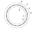
以下、本発明の第1実施形態に係るシリンダライナ、シリンダカバーおよび補強金物について、図1から図5を参照しながら説明する。
図1は本実施形態に係るシリンダライナの斜視図、図2は本実施形態に係る内燃機関の冷却構造を示す要部の断面図、図3は図2のIII-III矢視図、図4は図2の要部を拡大して示す図、図5は図4のV-V矢視図である。
図1から図5の少なくとも一図に示すように、本実施形態に係る補強金物10は、シリンダライナ20とシリンダカバー40との接合部において、シリンダライナ20とシリンダカバー40との双方に跨って、シリンダライナ20およびシリンダカバー40の外周面に嵌って、シリンダライナ20およびシリンダカバー40の外周面との間に冷却水通路(冷却水流路)11を形成するとともに、内燃機関運転時(温態時)におけるシリンダライナ20の半径方向外側への拡がりを抑制(拘束)するリング状(環状)の部材である。冷却水通路11は、補強金物10の下半部内周面12に、その長手方向軸線(中心軸線)が、シリンダ軸(シリンダライナ20の長手方向軸線)と平行になるとともに、補強金物10の周方向に沿って一定の間隔をあけて設けられた複数本の縦溝13と、補強金物10の上半部内周面14に、縦溝13と直交するとともに、補強金物10の周方向に沿って設けられた一本の(第1の)周溝15とで形成されている。縦溝13は、補強金物10の下半部内周面12から半径方向外側に向かって彫り込まれた(掘り下げられた)溝であり、周溝15は、補強金物10の上半部内周面14から半径方向外側に向かって彫り込まれた(掘り下げられた)溝である。
クーリングボア30は、傾斜面22と傾斜面26とを連通する直線状の穴である。すなわち、クーリングボア30の入口(木口)31は、傾斜面22に設けられており、クーリングボア30の出口(木口)32は、傾斜面26に設けられていて、クーリングボア30の長手方向軸線(中心軸線)は、シリンダ軸に垂直な平面に対して傾いている。
シリンダカバー40は、上部クーリングボア41と、下部クーリングボア(第2のクーリングボア)42とを備えている。
上部クーリングボア41は、補強金物10の上方(一方)に位置するシリンダカバー40の外周面に図示しないカバー外筒(水室金物)が嵌められた際に、シリンダカバー40の外周面に設けられた(第1の)水室43と、この水室43の上方(一方)に位置するシリンダカバー40の外周面に設けられた(第2の)水室44とを連通する直線状の穴であり、シリンダカバー40の周方向に沿って複数本設けられている。
なお、上部クーリングボア41の長手方向軸線(中心軸線)は、シリンダ軸に垂直な平面に対して傾いている。
なお、下部クーリングボア42の長手方向軸線(中心軸線)は、シリンダ軸に垂直な平面に対して傾いている。
なお、図2および図4中の符号45は、補強金物10の下半部内周面12、シリンダライナ20の傾斜面26,27とにより形成された(第3の)水室を示している。
これにより、シリンダライナ20の肉厚を低減させて、シリンダライナ20、シリンダカバー40および補強金物10の外径の小径化、軽量化を図ることができる。
これにより、シリンダライナ20の肉厚をさらに低減させて、シリンダライナ20、シリンダカバー40および補強金物10の外径の小径化、軽量化を図ることができるとともに、クーリングボア30の出口における応力集中を緩和(軽減)させることができる。
これにより、シリンダライナ20の肉厚をさらに低減させて、シリンダライナ20、シリンダカバー40および補強金物10の外径の小径化、軽量化を図ることができるとともに、クーリングボア30の出口32における応力集中をさらに緩和(軽減)させることができる。
このようにすることにより、クーリングボア30の出口32が、周溝29を形成する傾斜面26に、その平面視形状が円形状を呈するようにして設けられることになる。
これにより、シリンダライナ20の肉厚をさらに低減させて、シリンダライナ20、シリンダカバー40および補強金物10の外径の小径化、軽量化を図ることができるとともに、クーリングボア30の出口32における応力集中をさらに緩和(軽減)させることができる。
これにより、内燃機関休止時(冷態時)におけるシリンダカバーの、補強金物およびシリンダライナからの取り外し作業、補強金物の、シリンダライナからの取り外し作業を容易なものとすることができ、内燃機関運転時(温態時)における(ガスおよび冷却水の)シール性を向上させることができる。
なお、FC250は250N/mm2以上の引張強さが保証された片状黒鉛鋳鉄(ねずみ鋳鉄)、S25Cは炭素含有率0.25%の一般構造用炭素鋼、SS400は400N/mm2以上の引張強さが保証された一般構造用圧延鋼材のことである。
これにより、シリンダライナ20の肉厚を低減させて、シリンダライナ20の外径の小径化、軽量化を図ることができるとともに、クーリングボア30の出口32における応力集中を緩和(軽減)させることができる。
このようにすることにより、クーリングボア30の出口32が、周溝29を形成する傾斜面26に、その平面視形状が円形状を呈するようにして設けられることになる。
これにより、シリンダライナ20の肉厚をさらに低減させて、シリンダライナ20の外径の小径化、軽量化を図ることができるとともに、クーリングボア30の出口32における応力集中をさらに緩和(軽減)させることができる。
本発明の第2実施形態に係るシリンダライナ、シリンダカバーおよび補強金物について、図6を参照しながら説明する。
図6は本実施形態に係る補強金物の下半部内周面を、補強金物の中心側から見た図であって、図5と同様の図である。
本実施形態に係る補強金物50には、縦溝13の代わりに縦溝(斜溝)51が設けられているという点で上述した第1実施形態のものと異なる。その他の構成要素については上述した第1実施形態のものと同じであるので、ここではそれら構成要素についての説明は省略する。
なお、上述した第1実施形態と同一の部材には同一の符号を付している。
その他の作用効果は、上述した第1実施形態のものと同じであるので、ここではその説明を省略する。
本発明の第3実施形態に係るシリンダライナ、シリンダカバーおよび補強金物について、図7から図11を参照しながら説明する。
図7は本実施形態に係る内燃機関の冷却構造を示す要部の断面図であって、図2と同様の図、図8は図7のVIII-VIII矢視図、図9は図7の要部を拡大して示す図、図10は図9のX-X矢視図、図11は図9のXI-XI矢視図である。
本実施形態に係る補強金物60には、縦溝13の代わりに連通穴61が設けられているという点で上述した第1実施形態のものと異なる。その他の構成要素については上述した第1実施形態のものと同じであるので、ここではそれら構成要素についての説明は省略する。
なお、上述した第1実施形態と同一の部材には同一の符号を付している。
本発明の第4実施形態に係るシリンダライナ、シリンダカバーおよび補強金物について、図12を参照しながら説明する。
図12は本実施形態に係る内燃機関の冷却構造を示す要部を拡大して示す断面図である。
本実施形態に係る補強金物70は、シリンダライナ20とシリンダカバー90との、外周縁部における接合面を含む平面(水平面)71で、上下に二分割できるように構成されているという点で上述した第1実施形態および第2実施形態のものと異なる。その他の構成要素については上述した第1実施形態および第2実施形態のものと同じであるので、ここではそれら構成要素についての説明は省略する。
なお、上述した第1実施形態および第2実施形態と同一の部材には同一の符号を付している。
なお、図12中の符号81は、下半部74の内周面、シリンダライナ20の傾斜面26,27とにより形成された(第3の)水室を示し、図12中の符号82は、上半部73の内周面、シリンダカバー90の傾斜面96,97とにより形成された(第4の)水室を示している。
また、シリンダカバー90および73上半部と、シリンダライナ20および下半部74とは、シリンダライナ20とシリンダカバー90との接合面を含む平面71で分割されることになるので、ピストン抜き作業におけるピストンのつり上げ高さを従来と同じ高さにすることができ、機関室の天井高さを従来と同じ高さにすることができる。
その他の作用効果は、上述した第1実施形態および第2実施形態のものと同じであるので、ここではその説明を省略する。
11 冷却水通路
12 下半部内周面
20 シリンダライナ
26 傾斜面
29 周溝
30 (第1の)クーリングボア
32 出口
40 シリンダカバー
42 (第2の)クーリングボア
50 補強金物
60 補強金物
70 補強金物
71 平面
72 冷却水通路
90 シリンダカバー
Claims (9)
- 外周面から壁内に向かって斜め上方にあけられた第1のクーリングボアを複数本備えたシリンダライナと、
外周面から壁内に向かって斜め上方にあけられた第2のクーリングボアを複数本備え、前記シリンダライナの上に配置されて、前記シリンダライナの上方に位置する開口を塞ぐシリンダカバーと、を具備した内燃機関の冷却構造であって、
前記シリンダライナと前記シリンダカバーとの接合部において、前記シリンダライナと前記シリンダカバーとの双方に跨って、前記シリンダライナおよび前記シリンダカバーの外周面に嵌って、前記シリンダライナおよび前記シリンダカバーの外周面との間に冷却水通路を形成するとともに、内燃機関運転時における前記シリンダライナの半径方向外側への拡がりを抑制するリング状の補強金物を備えている内燃機関の冷却構造。 - 前記第1のクーリングボアの出口が、前記シリンダライナの板厚方向における中央部に設けられている請求項1に記載の内燃機関の冷却構造。
- 前記第1のクーリングボアの出口が、前記補強金物の下半部内周面と対向する前記シリンダライナの上端部外周面から半径方向内側に向かって彫り込まれて周溝を形成する傾斜面に設けられている請求項2に記載の内燃機関の冷却構造。
- 前記第1のクーリングボアの長手方向軸線が、前記傾斜面に対して直交するように、前記第1のクーリングボアおよび前記傾斜面が設けられている請求項3に記載の内燃機関の冷却構造。
- 前記シリンダライナおよび前記シリンダカバーが有する弾性係数よりも大きい弾性係数を有する金属材料で前記補強金物が作られている請求項1から4のいずれか一項に記載の内燃機関の冷却構造。
- 前記補強金物が、前記シリンダライナと前記シリンダカバーとの接合面を含む平面で、上下に二分割できるように構成されている請求項1から5のいずれか一項に記載の内燃機関の冷却構造。
- 外周面から壁内に向かって斜め上方にあけられた第1のクーリングボアを複数本備えたシリンダライナであって、
前記第1のクーリングボアの出口が、前記シリンダライナの板厚方向における中央部において、前記シリンダライナの上端部外周面から半径方向内側に向かって彫り込まれて周溝を形成する傾斜面に設けられてシリンダライナ。 - 前記第1のクーリングボアの長手方向軸線が、前記傾斜面に対して直交するように、前記第1のクーリングボアおよび前記傾斜面が設けられている請求項7に記載のシリンダライナ。
- 請求項1から6に記載の内燃機関の冷却構造または請求項7または8に記載のシリンダライナを具備している内燃機関。
Priority Applications (2)
| Application Number | Priority Date | Filing Date | Title |
|---|---|---|---|
| KR1020137004475A KR101465373B1 (ko) | 2011-01-31 | 2012-01-13 | 내연 기관의 냉각 구조 |
| CN201280002527.7A CN103080519B (zh) | 2011-01-31 | 2012-01-13 | 内燃机的冷却结构 |
Applications Claiming Priority (2)
| Application Number | Priority Date | Filing Date | Title |
|---|---|---|---|
| JP2011019088A JP5909043B2 (ja) | 2011-01-31 | 2011-01-31 | 内燃機関の冷却構造 |
| JP2011-019088 | 2011-01-31 |
Publications (1)
| Publication Number | Publication Date |
|---|---|
| WO2012105290A1 true WO2012105290A1 (ja) | 2012-08-09 |
Family
ID=46602511
Family Applications (1)
| Application Number | Title | Priority Date | Filing Date |
|---|---|---|---|
| PCT/JP2012/050544 Ceased WO2012105290A1 (ja) | 2011-01-31 | 2012-01-13 | 内燃機関の冷却構造 |
Country Status (4)
| Country | Link |
|---|---|
| JP (1) | JP5909043B2 (ja) |
| KR (1) | KR101465373B1 (ja) |
| CN (1) | CN103080519B (ja) |
| WO (1) | WO2012105290A1 (ja) |
Cited By (1)
| Publication number | Priority date | Publication date | Assignee | Title |
|---|---|---|---|---|
| US12473871B2 (en) | 2024-02-15 | 2025-11-18 | Progress Rail Locomotive Inc. | Cylinder liner having coolant flow balancer and engine power assembly using same |
Families Citing this family (4)
| Publication number | Priority date | Publication date | Assignee | Title |
|---|---|---|---|---|
| DK179020B1 (en) * | 2015-11-02 | 2017-08-28 | Man Diesel & Turbo Filial Af Man Diesel & Turbo Se Tyskland | A cylinder liner for a two-stroke crosshead engine |
| DK178939B1 (en) * | 2015-11-02 | 2017-06-19 | Man Diesel & Turbo Filial Af Man Diesel & Turbo Se Tyskland | A cylinder liner for a two-stroke crosshead engine |
| DK179175B1 (en) * | 2016-03-16 | 2018-01-08 | Man Diesel & Turbo Filial Af Man Diesel & Turbo Se Tyskland | A cylinder cover for a large two-stroke turbocharged compression-ignited internal combustion engine |
| DE202023102190U1 (de) | 2023-04-25 | 2023-05-04 | Innio Jenbacher Gmbh & Co Og | Zylinderlaufbuchse für eine Brennkraftmaschine |
Citations (2)
| Publication number | Priority date | Publication date | Assignee | Title |
|---|---|---|---|---|
| JPS62243944A (ja) * | 1986-04-14 | 1987-10-24 | Mitsubishi Heavy Ind Ltd | シリンダライナ及びシリンダカバ−構造 |
| JPH0742611A (ja) * | 1993-07-27 | 1995-02-10 | Mitsubishi Heavy Ind Ltd | シリンダライナ冷却通路 |
Family Cites Families (7)
| Publication number | Priority date | Publication date | Assignee | Title |
|---|---|---|---|---|
| JPS58167752U (ja) * | 1982-05-01 | 1983-11-09 | 三菱重工業株式会社 | ボアク−リング式エンジン |
| DE3417515C1 (de) * | 1984-05-11 | 1985-08-14 | Krupp Mak Maschinenbau Gmbh, 2300 Kiel | Brennkraftmaschine mit Kolbenlaufbuchsen |
| JPH05214933A (ja) * | 1992-02-06 | 1993-08-24 | Mitsubishi Heavy Ind Ltd | 内燃機関のシリンダ |
| JPH08200062A (ja) * | 1995-01-27 | 1996-08-06 | Mitsubishi Heavy Ind Ltd | 深溝冷却シリンダライナ |
| KR19980030646A (ko) * | 1996-10-30 | 1998-07-25 | 김영귀 | 자동차 실린더보어의 보강구조 |
| JP4182571B2 (ja) * | 1998-10-21 | 2008-11-19 | 東栄技工株式会社 | シリンダカバ−のボア−ク−ル穴部補修方法 |
| JP2004218546A (ja) * | 2003-01-15 | 2004-08-05 | Toyota Motor Corp | シリンダブロック、シリンダヘッド及びエンジン本体 |
-
2011
- 2011-01-31 JP JP2011019088A patent/JP5909043B2/ja not_active Expired - Fee Related
-
2012
- 2012-01-13 KR KR1020137004475A patent/KR101465373B1/ko not_active Expired - Fee Related
- 2012-01-13 WO PCT/JP2012/050544 patent/WO2012105290A1/ja not_active Ceased
- 2012-01-13 CN CN201280002527.7A patent/CN103080519B/zh not_active Expired - Fee Related
Patent Citations (2)
| Publication number | Priority date | Publication date | Assignee | Title |
|---|---|---|---|---|
| JPS62243944A (ja) * | 1986-04-14 | 1987-10-24 | Mitsubishi Heavy Ind Ltd | シリンダライナ及びシリンダカバ−構造 |
| JPH0742611A (ja) * | 1993-07-27 | 1995-02-10 | Mitsubishi Heavy Ind Ltd | シリンダライナ冷却通路 |
Cited By (1)
| Publication number | Priority date | Publication date | Assignee | Title |
|---|---|---|---|---|
| US12473871B2 (en) | 2024-02-15 | 2025-11-18 | Progress Rail Locomotive Inc. | Cylinder liner having coolant flow balancer and engine power assembly using same |
Also Published As
| Publication number | Publication date |
|---|---|
| CN103080519B (zh) | 2015-05-06 |
| KR20130029821A (ko) | 2013-03-25 |
| JP5909043B2 (ja) | 2016-04-26 |
| JP2012159035A (ja) | 2012-08-23 |
| CN103080519A (zh) | 2013-05-01 |
| KR101465373B1 (ko) | 2014-11-26 |
Similar Documents
| Publication | Publication Date | Title |
|---|---|---|
| JP5909043B2 (ja) | 内燃機関の冷却構造 | |
| US10125870B2 (en) | Piston ring | |
| JP5162655B2 (ja) | 内燃機関用のピストン | |
| JP2009091927A (ja) | 往復動機関のピストンリング | |
| JP2018200104A (ja) | 主燃焼封止型押しの内部の小型弾性封止特徴 | |
| CN101251059B (zh) | 气缸盖密封垫 | |
| JP5721595B2 (ja) | 内燃機関の冷却構造 | |
| JP5468673B1 (ja) | ガスケットとシリンダヘッドガスケット | |
| JP2016527460A (ja) | ピストンリング | |
| JP6546274B2 (ja) | 高温内燃機関のためのキーストーン形の第2のリング溝を有するピストン | |
| US9188080B2 (en) | Gasket and engine with the gasket | |
| JP6261857B2 (ja) | シリンダカバー、シリンダヘッドガスケット及び内燃機関 | |
| CN204877696U (zh) | 用于发动机的汽缸衬套及内燃机 | |
| KR20080078549A (ko) | 실린더 헤드 개스킷 | |
| JP5656506B2 (ja) | シリンダライナ | |
| JP2011111954A (ja) | シリンダブロック、シリンダヘッド間の締結構造 | |
| JP6514216B2 (ja) | ピストンリング溝、特にコンプレッション溝を有するピストン | |
| JP2009185865A (ja) | ピストンリング、並びに、これを適用したピストン及びエンジン | |
| JP4427506B2 (ja) | 内燃機関用ピストン | |
| JP6048179B2 (ja) | ピストン及び内燃機関 | |
| KR100916453B1 (ko) | 내연기관의 피스톤 링 구조 | |
| JP4889975B2 (ja) | ピストン装置 | |
| JP2010270801A (ja) | 組合せオイルリング | |
| JP6308192B2 (ja) | レシプロ式エンジン | |
| JP2002235603A (ja) | エンジンのシール構造 |
Legal Events
| Date | Code | Title | Description |
|---|---|---|---|
| WWE | Wipo information: entry into national phase |
Ref document number: 201280002527.7 Country of ref document: CN |
|
| 121 | Ep: the epo has been informed by wipo that ep was designated in this application |
Ref document number: 12741777 Country of ref document: EP Kind code of ref document: A1 |
|
| ENP | Entry into the national phase |
Ref document number: 20137004475 Country of ref document: KR Kind code of ref document: A |
|
| NENP | Non-entry into the national phase |
Ref country code: DE |
|
| 122 | Ep: pct application non-entry in european phase |
Ref document number: 12741777 Country of ref document: EP Kind code of ref document: A1 |