WO2012091069A1 - 金型の焼入れ方法 - Google Patents
金型の焼入れ方法 Download PDFInfo
- Publication number
- WO2012091069A1 WO2012091069A1 PCT/JP2011/080342 JP2011080342W WO2012091069A1 WO 2012091069 A1 WO2012091069 A1 WO 2012091069A1 JP 2011080342 W JP2011080342 W JP 2011080342W WO 2012091069 A1 WO2012091069 A1 WO 2012091069A1
- Authority
- WO
- WIPO (PCT)
- Prior art keywords
- mold
- temperature
- cooling
- quenching
- oil
- Prior art date
- Legal status (The legal status is an assumption and is not a legal conclusion. Google has not performed a legal analysis and makes no representation as to the accuracy of the status listed.)
- Ceased
Links
Images

Classifications
-
- C—CHEMISTRY; METALLURGY
- C21—METALLURGY OF IRON
- C21D—MODIFYING THE PHYSICAL STRUCTURE OF FERROUS METALS; GENERAL DEVICES FOR HEAT TREATMENT OF FERROUS OR NON-FERROUS METALS OR ALLOYS; MAKING METAL MALLEABLE, e.g. BY DECARBURISATION OR TEMPERING
- C21D1/00—General methods or devices for heat treatment, e.g. annealing, hardening, quenching or tempering
- C21D1/18—Hardening; Quenching with or without subsequent tempering
-
- B—PERFORMING OPERATIONS; TRANSPORTING
- B22—CASTING; POWDER METALLURGY
- B22D—CASTING OF METALS; CASTING OF OTHER SUBSTANCES BY THE SAME PROCESSES OR DEVICES
- B22D30/00—Cooling castings, not restricted to casting processes covered by a single main group
-
- C—CHEMISTRY; METALLURGY
- C21—METALLURGY OF IRON
- C21D—MODIFYING THE PHYSICAL STRUCTURE OF FERROUS METALS; GENERAL DEVICES FOR HEAT TREATMENT OF FERROUS OR NON-FERROUS METALS OR ALLOYS; MAKING METAL MALLEABLE, e.g. BY DECARBURISATION OR TEMPERING
- C21D1/00—General methods or devices for heat treatment, e.g. annealing, hardening, quenching or tempering
- C21D1/18—Hardening; Quenching with or without subsequent tempering
- C21D1/19—Hardening; Quenching with or without subsequent tempering by interrupted quenching
-
- C—CHEMISTRY; METALLURGY
- C21—METALLURGY OF IRON
- C21D—MODIFYING THE PHYSICAL STRUCTURE OF FERROUS METALS; GENERAL DEVICES FOR HEAT TREATMENT OF FERROUS OR NON-FERROUS METALS OR ALLOYS; MAKING METAL MALLEABLE, e.g. BY DECARBURISATION OR TEMPERING
- C21D1/00—General methods or devices for heat treatment, e.g. annealing, hardening, quenching or tempering
- C21D1/56—General methods or devices for heat treatment, e.g. annealing, hardening, quenching or tempering characterised by the quenching agents
-
- C—CHEMISTRY; METALLURGY
- C21—METALLURGY OF IRON
- C21D—MODIFYING THE PHYSICAL STRUCTURE OF FERROUS METALS; GENERAL DEVICES FOR HEAT TREATMENT OF FERROUS OR NON-FERROUS METALS OR ALLOYS; MAKING METAL MALLEABLE, e.g. BY DECARBURISATION OR TEMPERING
- C21D1/00—General methods or devices for heat treatment, e.g. annealing, hardening, quenching or tempering
- C21D1/56—General methods or devices for heat treatment, e.g. annealing, hardening, quenching or tempering characterised by the quenching agents
- C21D1/58—Oils
-
- C—CHEMISTRY; METALLURGY
- C21—METALLURGY OF IRON
- C21D—MODIFYING THE PHYSICAL STRUCTURE OF FERROUS METALS; GENERAL DEVICES FOR HEAT TREATMENT OF FERROUS OR NON-FERROUS METALS OR ALLOYS; MAKING METAL MALLEABLE, e.g. BY DECARBURISATION OR TEMPERING
- C21D9/00—Heat treatment, e.g. annealing, hardening, quenching or tempering, adapted for particular articles; Furnaces therefor
- C21D9/0068—Heat treatment, e.g. annealing, hardening, quenching or tempering, adapted for particular articles; Furnaces therefor for particular articles not mentioned below
Definitions
- the present invention relates to a mold quenching method.
- the mold is required to have high hardness and high toughness, and its characteristics are greatly influenced by the quenching method.
- a higher quenching temperature is selected so that the crystal grains are not coarsened in order to dissolve the alloy elements to the maximum.
- rapid cooling is required.
- rapid cooling increases the distortion and deformation of the mold, and thus it is necessary to appropriately control the cooling rate. For this reason, various proposals have been made in the past, and a method of achieving both low strain and high toughness by adjusting the cooling conditions from the quenching temperature is mainly employed.
- Patent Document 1 cooling subsequent to heating to the quenching temperature is set to 20 ° C./min to 5 ° C./min in the high temperature region from the quenching temperature to 600 ° C.
- a marquenching method has been proposed in which the low temperature region from 400 ° C. to 200 ° C. is maintained at 1 ° C./min to 15 ° C./min after being held.
- the marquenching method is a process in which the cooling during quenching is kept constant at the upper part of the martensite transformation or at a slightly higher temperature to cool after quenching, in order to prevent quench cracking due to rapid cooling. is there.
- the present applicant has proposed a method for quenching a mold in JP 2009-074155 A (Patent Document 2), focusing on both the temperature raising side condition and the cooling side condition of the quenching temperature. That is, after the quenching and heating step of heating the temperature range from the A1 transformation point to the A3 transformation point at a rate of 100 ° C./h or more, a holding step for holding a temperature range not lower than 1150 ° C. above the A3 transformation point is performed. Next, a high temperature side quenching and cooling process is performed in which the temperature range from the A3 transformation point to 600 ° C.
- Patent Document 3 discloses techniques related to a quenching method by the same applicant. Specifically, a steel part is rapidly cooled to a temperature just above the martensite transformation start point (Ms point), taken out of the quenching oil, and immediately above the martensite transformation start point (Ms point) by the retained heat of the steel part. This is a technology that maintains a constant temperature until the temperature reaches a nearby temperature.
- a material having a small internal volume such as a part such as a gear illustrated in paragraph 0002 of cited document 3 or a sharpened portion such as a corner portion of a prism member illustrated in paragraph 0009 of cited document 4, is preferably quenched. it can.
- Patent Document 3 and Patent Document 4 when the techniques disclosed in Patent Document 3 and Patent Document 4 are applied to a mold having a larger volume than a gear or the like, it is difficult to control the cooling rate, and the surface of the mold is Ms during rapid cooling. The temperature falls below the point. At this time, there is almost no temperature drop inside the mold, and if it is taken out from the quenching oil, the surface temperature again becomes higher than the Ms point due to the retained heat inside the mold, the metal structure becomes unstable, and the mold becomes unstable. Hardness variation will occur. In the case of a heavy mold, if an attempt is made to maintain a constant temperature until it reaches a temperature just above the Ms point, the time required for the mold becomes too long, and the productivity is remarkably deteriorated.
- An object of the present invention is to provide a quenching method capable of rationally improving the toughness of the mold surface.
- the present inventor In order to improve the toughness of the surface of the hot mold, the present inventor 1) It is necessary to apply a cooling rate much faster than the cooling rate considering the transformation region of bainite (bainite nose) in order to reliably avoid carbide precipitation at the grain boundaries. and, 2) The adverse effects due to the temperature difference between the surface and the interior due to the application of this fast cooling rate can be reasonably eliminated by appropriately managing the cooling interruption state. And reached the present invention.
- the present invention A heating / holding step of heating the mold and holding it in a temperature range from the A3 transformation point to 1150 ° C, After the heating / holding step, a first cooling step of immersing the mold in an oil bath and cooling to a temperature at which the surface temperature of the mold is 700 ° C.
- the mold is lifted from the oil tank to interrupt the oil cooling, and the surface temperature of the mold exceeds the Ms point, and the temperature difference between the mold surface and the inside Improved holding step for holding until the temperature is within 200 ° C.
- a second cooling step of cooling at a rate of 1 ° C./min to 50 ° C./min until the surface temperature of the mold reaches 200 ° C .
- the present invention provides the improved holding step in which the mold is lifted from the oil tank and the oil cooling is interrupted, and the immersion and the pulling are performed again in a temperature range where the surface temperature of the mold exceeds the Ms point. You may change to the process repeated until the temperature difference of the surface of a type
- the mold is quenched by cooling at a rate of 1 ° C./min to 15 ° C./min until the temperature inside the mold drops from 400 ° C. to 250 ° C. More preferably, the second cooling step is oil cooling. More preferably, the environment in the first cooling step, the improved holding step, and the second cooling step is a non-oxidizing atmosphere.
- the mold toughening method of the present invention can improve the surface toughness of the mold, it can be expected to improve the life of the mold.
- the temperature of the heating / holding step of the present invention is set to a temperature range not lower than 1150 ° C. above the A3 transformation point. This is because if this temperature is lower than the A3 transformation point, the solid solution of carbides and alloy elements is insufficient, the hardness is low, and the high temperature strength is also low, so heat cracks are likely to occur. Further, when the temperature exceeds 1150 ° C., the carbide pinning the crystal grains also dissolves and the crystal grains grow abnormally. In order to suppress the occurrence of these problems and achieve the refinement of crystal grains, a temperature range from the A3 transformation point to below 1150 ° C. is required. Preferably it is the temperature range of 1010 degreeC or more and less than 1150 degreeC.
- the cooling process of the present invention will be described.
- the mold is immersed in an oil tank and cooled until the surface temperature of the mold becomes 700 ° C. or lower (temperature exceeding the Ms point) by oil cooling.
- a process is performed (FIG. 1 (5)).
- the reason why the first cooling step is oil-cooled in the present invention is that a region in which carbide precipitates at the grain boundaries can be surely avoided. This oil cooling surely increases the toughness of the mold surface.
- the reason why oil cooling is selected in the present invention is that if it is oil cooling, the cooling capacity can be suitably adjusted by adjusting the temperature of the quenching oil.
- the cooling rate is too high, and there is a high risk that the mold surface will undergo martensitic transformation in the first cooling process. This is because there is a possibility that the cooling of the mold surface slows down and passes through the carbide precipitation region.
- the cooling speed of the mold surface in the first cooling step by oil cooling is approximately 80 ° C / min to 250 ° C / min, depending on the size of the mold, and it is possible to use conventional blast cooling or liquid spraying. Compared with the quenching method of the mold, the cooling rate is much faster. In the first cooling step, cooling until the surface temperature of the mold becomes 700 ° C.
- the toughness of the mold surface and the vicinity thereof can be improved by the first cooling step by oil cooling described above.
- an improved holding process is performed. (Fig. 1 (6) and Fig. 2) Since a remarkably fast cooling rate is applied in the first cooling step, the temperature difference between the mold surface and the inside becomes large. In the improved holding process, this is quickly reduced to alleviate the thermal stress. There are two methods for this improved holding process.
- the first improved holding process is a method of lifting the mold from the oil tank, interrupting the oil rejection, and allowing it to cool.
- This method a large amount of heat inside the mold is transferred to the mold surface, and the surface temperature rises. Thereby, the temperature difference between the mold surface and the inside is quickly reduced.
- the second improved holding step is a method of repeatedly immersing the mold in the oil tank and pulling it up from the oil tank.
- the temperature difference between the mold surface and the inside is quickly relaxed as in the first improved holding step, and the following effects can also be obtained.
- (1) The amount of heat removed from the mold can be increased, and the cooling rate inside the mold can be increased. As a result, generation of pearlite inside the mold can be prevented more reliably.
- (2) The cooling rate inside the mold surface and inside the mold is increased, and it is possible to cool the inside of the mold while avoiding the carbide precipitation region.
- Since the cooling speed of the whole mold is fast, it is particularly suitable for quenching large molds of 200 kg or more.
- the time required for quenching can be shortened and productivity can be improved.
- the first time may be raised before the mold surface falls below 400 ° C. This is because the mold is often a heavy object, and if the mold is excessively cooled to the vicinity of the Ms point, the temperature difference between the mold surface and the inside of the mold is widened and the mold is easily deformed.
- Which one of the first improvement holding process and the second improvement holding process described above is selected is determined, for example, in consideration of the weight and processing time of the mold, and the surface area and volume of the mold. good.
- the second improved holding process is suitable for processing a mold of 100 kg or more in a short time.
- the two improved holding steps described above are performed until the temperature difference between the surface and the inside of the mold reaches 200 ° C. or less by oil cooling. This is because if the temperature difference exceeds 200 ° C. and the second cooling step is performed, there is a risk of distortion or deformation due to the thermal stress difference. In order to prevent distortion and deformation more reliably, the temperature difference between the surface of the mold and the inside is preferably within 150 ° C. In addition, since some molds exceed 100 kg and are about 2 tons heavy, if the temperature is kept constant until the temperature is just above the Ms point as in the prior art, the processing time becomes longer and the productivity is significantly reduced.
- the second cooling step may be performed when the temperature difference between the surface of the mold and the inside becomes 50 ° C. to 200 ° C. (preferably 50 ° C. to 150 ° C.). .
- a constant temperature holding furnace or a salt bath which has been required in conventional marquenches, can be eliminated.
- a second cooling step is performed in which the mold is cooled at a rate of 1 ° C./min to 50 ° C./min until the mold surface temperature reaches 200 ° C. (Fig. 1 (7))
- the cooling rate of this second cooling step suppresses the generation of bainite of the material to be heat-treated (mold) during cooling, and also suppresses temperature unevenness due to rapid cooling, and controls toughness, quenching distortion, and cracking. This is the cooling rate necessary for this.
- the cooling rate of the surface temperature is less than 1 ° C./min, the suppression of bainite formation is insufficient and the toughness is lowered.
- a preferable cooling rate of the surface temperature is 10 ° C./min to 30 ° C./min.
- the cooling rate at the center is also important from the viewpoint of controlling the metal structure, and the region of 400 ° C. to 250 ° C. where bainite is generated is cooled at 1 ° C./min to 15 ° C./min. good. If it is this range, the production
- this second cooling step it is 5 ° C./min to 15 ° C./min, and the above effect can be obtained more reliably.
- this second cooling step it is easy to adjust the cooling rate to the above-mentioned temperature range, and in particular, the metal structure inside the heat-treated material is not likely to be a massive bainite structure, and it is easy to obtain a cooling rate, which is oil cooling. Is good.
- the environment in the first cooling step, the improved holding step, and the second cooling step described above is preferably a non-oxidizing atmosphere.
- nitrogen, an inert gas, or a vacuum atmosphere (reduced pressure atmosphere) can be applied. This is because the quenching oil burns violently to cause a disaster such as a fire because the first cooling process is a rapid cooling from the quenching temperature to the oil tank.
- oxidation and decarburization of the heat-treated material can be prevented.
- the conditions for heating to the above quenching temperature will be described.
- the low temperature side here means the temperature range below the A1 transformation point.
- the condition for the low temperature side quenching temperature raising step is preferably a temperature rising rate of 200 ° C./h or less. This is because if the rate of temperature increase is too high, the material to be heat treated may be distorted, or the temperature difference between the surface layer portion and the inside of the material to be heat treated will increase, resulting in variations in crystal grains depending on the part. This is because it becomes higher.
- a preferred rate of temperature rise is in the range of 50 ° C./h to 150 ° C./h.
- the temperature holding process which hold maintains temperature more than once in the middle of the above-mentioned low temperature side hardening temperature rising process (FIG. 1 (2)).
- the temperature holding step By performing the temperature holding step, the temperature unevenness when the heat-treated material is heated is reduced, so that deformation is reduced. Further, the processing residual stress generated at the time of mold manufacture is removed by preheating, and there is also an effect of suppressing abnormal growth of crystal grains using residual strain as a driving force when passing through the transformation point by subsequent heating.
- the temperature holding step is preferably performed in the temperature range of A1 transformation point ⁇ 200 ° C. to A1 transformation point ⁇ 15 ° C.
- the temperature range is from A1 transformation point to -70 ° C to A1 transformation point to -20 ° C.
- the temperature holding time is intended to reduce the temperature unevenness when the heat-treated material is heated as described above, and therefore it is difficult to obtain the effect of reducing the temperature unevenness in a very short time. Therefore, it is preferable to set a time sufficient to reduce the temperature unevenness. Although the time cannot be generally determined depending on the weight and shape of the material to be heat-treated, it is preferable to hold it for about 0.5 to 5 hours from experience. If held for 0.75 hours or longer, the difference between the surface layer temperature and the internal temperature can be kept within 30 ° C., so it is preferable to hold it for 0.75 hours (45 minutes) or longer.
- the temperature range from the A1 transformation point to the A3 transformation point may be heated at a rate of 100 ° C./h or more as a high temperature side temperature raising step (FIG. 1 (3)).
- a high temperature side temperature raising step FOG. 1 (3)
- the non-heat treated member can be adjusted to uniform crystal grains by adjusting the conditions of the temperature raising step up to the heating / holding step.
- Quenching treatment was performed using the above sample.
- the temperature conditions up to the heating / holding step are as follows. ⁇ First sample> The first sample was inserted into a quenching furnace, and the temperature increase was started. The conditions of the low temperature side temperature raising step (1) were 150 ° C./h, and the temperature holding step (2) was performed at 800 ° C. for 4 hours. Then, it heated up to 1025 degreeC on 150 degreeC / h conditions as a high temperature side temperature rising process (3), and moved to the heating and holding process (4).
- ⁇ Second sample> The second sample was inserted into the quenching furnace and the temperature increase was started.
- the conditions of the low temperature side temperature rising step (1) were 200 ° C./h, and the temperature holding step (2) was performed at 800 ° C. for 2 hours. Then, it heated up to 1025 degreeC on 200 degreeC / h conditions as a high temperature side temperature rising process (3), and moved to the heating and holding process (4).
- the first improved holding step and measurement temperature applied to the first sample, and the second cooling step, and the second improved holding step and measured temperature applied to the second sample, and the second Table 3 shows the cooling process.
- the temperature is a result of measuring the vicinity of the surface and the inside (center portion) by forming a drilling hole in the sample and inserting a thermocouple thermometer.
- the Charpy impact test was a 2 mm U notch test.
- Table 4 shows the Charpy impact values.
- the “comparative example” in Table 4 is the “No. This is a test result of 6 alloys (JIS SKD61 equivalent alloy), which is due to cooling by the conventional marquenching method.
- This comparative example (No. 6 of Patent Document 2) has almost the same thermal history as the example performed this time, and the quenching conditions are as follows. The test piece was heated at 75 ° C./h (low temperature side heating step (1)) and held at 800 ° C. for 1 hour (temperature holding step (2)), and the temperature was increased to 1020 ° C.
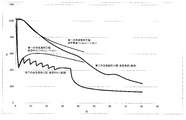
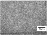
- FIG. 2 shows the measured values of the heat pattern after the first cooling step for the second sample, and the simulation result when the dipping and lifting are performed only once (adopting the first improved holding step). (Corresponding to the result) was plotted. As shown in FIG. 2, it can be seen that the internal (center) cooling rate is faster when immersion and pulling are repeated. It can also be confirmed that the overall cooling rate is fast. From these results, it can be seen that the present invention in which the second improved holding step is particularly suitable for quenching a heavy mold. In addition, as a result of cutting out the test piece for micro observation from the surface side of the 2nd sample and investigating the presence or absence of grain boundary precipitation, as shown in FIG. 3, the grain boundary precipitate could hardly be confirmed. Moreover, the dimensional change amount was about 0.5 mm at the maximum, and it was confirmed that the dimensional change could be suppressed.
- the mold quenching method of the present invention can improve the toughness of the mold, it can be expected to improve the life of the mold. Therefore, not only the mold but also the other application can be expected as a quenching method capable of improving toughness. In particular, the larger the heat-treated material, the better the improvement effect can be expected.
Landscapes
- Chemical & Material Sciences (AREA)
- Engineering & Computer Science (AREA)
- Mechanical Engineering (AREA)
- Physics & Mathematics (AREA)
- Thermal Sciences (AREA)
- Crystallography & Structural Chemistry (AREA)
- Materials Engineering (AREA)
- Metallurgy (AREA)
- Organic Chemistry (AREA)
- Oil, Petroleum & Natural Gas (AREA)
- Heat Treatment Of Articles (AREA)
Abstract
金型を加熱してA3変態点以上から1150℃未満の温度範囲に保持する加熱・保持工程と、前記加熱・保持工程の後、前記金型を油槽に浸漬し、油冷により金型の表面温度が700℃以下であってMs点は超えている温度まで冷却する第一の冷却工程と、前記第一の冷却工程の後、前記金型を油槽から引き上げて油冷を中断し、前記金型の表面温度がMs点を超える温度域であって前記金型の表面と内部との温度差が200℃以内となるまで保持する改良保持工程と、前記改良保持工程の後、前記金型の表面温度が200℃となるまで1℃/分~50℃/分の速度で冷却する第二の冷却工程と、を具備した金型の焼入れ方法。
Description
本発明は、金型の焼入れ方法に関する。
金型には高硬度、高靭性が要求され、その特性は焼入れ方法により大きく影響される。
昇温の際には、合金元素を最大限固溶させるため、結晶粒が粗大化しない範囲で高めの焼入れ温度が選定される。また、焼入れの際には、高靭性を得るために、結晶粒を微細化するのと同時に、結晶粒界への炭化物析出を抑え、ベイナイト変態も防止する必要がある。このとき、急冷が求められるが、一方、急冷すると金型の歪み、変形が大きくなるため、冷却速度を適切にコントロールする必要がある。このため、従来から種々の提案がなされており、主として、焼入れ温度からの冷却条件を調整して、低歪みと高靭性の両立を達成するといった方法が採用されている。
昇温の際には、合金元素を最大限固溶させるため、結晶粒が粗大化しない範囲で高めの焼入れ温度が選定される。また、焼入れの際には、高靭性を得るために、結晶粒を微細化するのと同時に、結晶粒界への炭化物析出を抑え、ベイナイト変態も防止する必要がある。このとき、急冷が求められるが、一方、急冷すると金型の歪み、変形が大きくなるため、冷却速度を適切にコントロールする必要がある。このため、従来から種々の提案がなされており、主として、焼入れ温度からの冷却条件を調整して、低歪みと高靭性の両立を達成するといった方法が採用されている。
例えば、特開2006-342377号公報(特許文献1)には、焼入れ温度への加熱に続く冷却を、焼入れ温度から600℃までの高温領域は20℃/分~5℃/分とし、次いで恒温保持してから、400℃から200℃までの低温領域は1℃/分~15℃/分となるように実施するマルクエンチ法が提案されている。これにより、焼割れを避けて、低歪みかつ高靱性の金型を得ることができるとされている。マルクエンチ法は、急冷による焼割れを防止するために、焼入れ時の冷却を、マルテンサイト変態の上部、またはそれよりやや高い温度で恒温保持して、各部の温度が均一化した後に冷却する処理である。
また、本出願人は特開2009-074155号公報(特許文献2)において、焼入れ温度の昇温側条件と、冷却側条件との両方に着目した金型の焼入れ方法を提案した。すなわち、A1変態点からA3変態点の温度域を100℃/h以上の速度で加熱する焼入れ昇温工程の後、A3変態点以上で1150℃を超えない温度域を保持する保持工程を行い、次いでA3変態点から600℃までの温度域を5℃/分~20℃/分の速度で冷却する高温側焼入冷却工程を行い、500℃~400℃までの温度域にて0.5時間~5時間保持する中断保持工程を経た後、400℃~200℃の温度域を1℃/分~15℃/分の速度で冷却する低温側焼入冷却工程を経る方法である。
また、特開2001-152243号公報(特許文献3)、特開2002-309314号公報(特許文献4)は、同一出願人による焼入れ方法に関する技術が開示されている。具体的には、鋼材部品を、マルテンサイト変態開始点(Ms点)の直上温度まで急冷し、焼入れ油の中から取り出し、当該鋼材部品の保有熱によりマルテンサイト変態開始点(Ms点)の直上近傍の温度になるまで恒温保持する技術である。これにより、引用文献3の0002段落に例示される歯車等の部品や、引用文献4の0009段落に例示される角柱部材のコーナー部などの先鋭部、といった内部体積の小さなものを好適に焼入れ処理できる。
本発明者らも、マルクエンチ法を検討してきたが、上述した特許文献1および特許文献2に開示される条件では、金型の表面の靭性が不足し、更に改善の余地があることを認識した。
また、特許文献3および特許文献4に開示される技術を、歯車等より一般的に体積が大である金型に適用すると、冷却速度のコントロールが難しく、急冷の際、金型の表面がMs点以下の温度に低下してしまう。このとき、金型内部は殆ど温度低下が見られず、焼入れ油から取り出すと、金型内部の保有熱により再び表面の温度がMs点以上となり、金属組織が不安定となって、金型に硬さのばらつきが生じてしまう。また、重量の大きな金型の場合では、Ms点直上近傍の温度になるまで恒温保持しようとすると、それに必要な時間が長くなり過ぎ、生産性も著しく悪くなってしまう。
本発明の目的は、特に金型表面の靭性を合理的に改善できる焼入れ方法を提供することである。
本発明者は、熱間金型の表面の靭性を改善するためには、
1)結晶粒界への炭化物析出を確実に避けるため、ベイナイトの変態領域(ベイナイトノーズ)を考慮した冷却速度よりも遥かに早い冷却速度を適用する必要があること、
および、
2)この早い冷却速度の適用による表面と内部の温度差による弊害は、冷却中断状態を適正に管理することにより合理的に解消できること、
を見出し本発明に到達した。
1)結晶粒界への炭化物析出を確実に避けるため、ベイナイトの変態領域(ベイナイトノーズ)を考慮した冷却速度よりも遥かに早い冷却速度を適用する必要があること、
および、
2)この早い冷却速度の適用による表面と内部の温度差による弊害は、冷却中断状態を適正に管理することにより合理的に解消できること、
を見出し本発明に到達した。
すなわち本発明は、
金型を加熱してA3変態点以上から1150℃未満の温度範囲に保持する加熱・保持工程と、
前記加熱・保持工程の後、前記金型を油槽に浸漬し、油冷により金型の表面温度が700℃以下であってMs点は超えている温度まで冷却する第一の冷却工程と、
前記第一の冷却工程の後、前記金型を油槽から引き上げて油冷を中断し、前記金型の表面温度がMs点を超える温度域であって前記金型の表面と内部との温度差が200℃以内となるまで保持する改良保持工程と、
前記改良保持工程の後、前記金型の表面温度が200℃となるまで1℃/分~50℃/分の速度で冷却する第二の冷却工程と、
を具備したことを特徴とする金型の焼入れ方法である。
金型を加熱してA3変態点以上から1150℃未満の温度範囲に保持する加熱・保持工程と、
前記加熱・保持工程の後、前記金型を油槽に浸漬し、油冷により金型の表面温度が700℃以下であってMs点は超えている温度まで冷却する第一の冷却工程と、
前記第一の冷却工程の後、前記金型を油槽から引き上げて油冷を中断し、前記金型の表面温度がMs点を超える温度域であって前記金型の表面と内部との温度差が200℃以内となるまで保持する改良保持工程と、
前記改良保持工程の後、前記金型の表面温度が200℃となるまで1℃/分~50℃/分の速度で冷却する第二の冷却工程と、
を具備したことを特徴とする金型の焼入れ方法である。
また本発明は、前記改良保持工程を、前記金型を油槽から引き上げて油冷を中断し、再度の浸漬および引き上げを、前記金型の表面温度がMs点を超える温度域であって前記金型の表面と内部との温度差が200℃以内となるまで繰り返す工程に変更しても良い。このとき、引き上げ回数が3回以上であることが好ましい。
好ましくは、前記第二の冷却工程では、金型内部の温度が400℃から250℃に下がるまで1℃/分~15℃/分の速度で冷却する金型の焼入れ方法である。
更に好ましくは、前記第二の冷却工程は、油冷とする。
更に好ましくは、前記第一の冷却工程、改良保持工程、および、第二の冷却工程における環境は、非酸化性雰囲気とする。
好ましくは、前記第二の冷却工程では、金型内部の温度が400℃から250℃に下がるまで1℃/分~15℃/分の速度で冷却する金型の焼入れ方法である。
更に好ましくは、前記第二の冷却工程は、油冷とする。
更に好ましくは、前記第一の冷却工程、改良保持工程、および、第二の冷却工程における環境は、非酸化性雰囲気とする。
本発明の金型の焼入れ方法により、特に金型の表面靭性を改善することができるため、金型の寿命を向上させることが期待できる。
上述したように、本発明の重要な特徴は、金型の焼入れ方法において、焼入れ時の冷却条件を最適化したことにある。以下に本発明を説明する。
先ず、加熱・保持工程について説明する(図1(4))。
本発明の加熱・保持工程の温度は、A3変態点以上で1150℃を超えない温度域に設定する。これは、この温度がA3変態点未満であると、炭化物や合金元素の固溶が不十分で、硬さが低く、また高温強度も低いためヒートクラックが発生しやすくなるからである。また、温度が1150℃を超えると、結晶粒をピンニングしている炭化物も固溶し、結晶粒が異常成長するからである。
これらの問題の発生を抑制し、結晶粒の微細化を達成するには、A3変態点以上で1150℃未満の温度範囲が必要となる。好ましくは1010℃以上1150℃未満の温度範囲である。
先ず、加熱・保持工程について説明する(図1(4))。
本発明の加熱・保持工程の温度は、A3変態点以上で1150℃を超えない温度域に設定する。これは、この温度がA3変態点未満であると、炭化物や合金元素の固溶が不十分で、硬さが低く、また高温強度も低いためヒートクラックが発生しやすくなるからである。また、温度が1150℃を超えると、結晶粒をピンニングしている炭化物も固溶し、結晶粒が異常成長するからである。
これらの問題の発生を抑制し、結晶粒の微細化を達成するには、A3変態点以上で1150℃未満の温度範囲が必要となる。好ましくは1010℃以上1150℃未満の温度範囲である。
次に、本発明の冷却工程について説明する。
本発明では、加熱・保持工程の後、金型を油槽に浸漬し油冷により金型の表面温度が700℃以下の温度(但し、Ms点を超える温度)となるまで冷却する第一の冷却工程を行う(図1(5))。
本発明で第一の冷却工程を油冷とするのは、結晶粒界に炭化物が析出する領域を確実に避けることができるためである。この油冷により、金型表面の靭性が確実に高まる。
本発明で油冷を選択したのは、油冷であると焼入れ油の温度の調節により、冷却能を好適に調節することも可能であるためである。例えば、冷却能の高い水冷とすると冷却速度が速すぎて、第一の冷却工程で金型表面がマルテンサイト変態する危険性が高く、また、冷却能の低い衝風冷却や液体噴霧では、金型表面の冷却が遅くなって炭化物析出領域を経る可能性があるためである。
なお、油冷による第一の冷却工程の金型表面の冷却速度は金型の大きさにもよるが、おおよそ80℃/分~250℃/分程度であり、従来の衝風冷却や液体噴霧による金型の焼入れ方法と比較して遥かに速い冷却速度である。
また、第一の冷却工程において、金型の表面温度が700℃以下となるまで冷却するのは、700℃を超える温度領域で油冷を中断すると、結晶粒界に炭化物が析出する可能性があるためである。析出の可能性をなくすためには、金型の表面温度がMs点を超えてMs点+200℃の温度範囲に至るまで油冷を行う。なお、表面温度をMs点以下まで冷却すると、金型の表面近傍の金属組織がマルテンサイト変態して、次の改良保持工程時で金属組織が不均一となる。そのため、本発明では表面温度の管理が重要となる。
本発明では上述した油冷による第一の冷却工程により、特に金型表面とその近傍領域の靭性を向上させることができる。
本発明では、加熱・保持工程の後、金型を油槽に浸漬し油冷により金型の表面温度が700℃以下の温度(但し、Ms点を超える温度)となるまで冷却する第一の冷却工程を行う(図1(5))。
本発明で第一の冷却工程を油冷とするのは、結晶粒界に炭化物が析出する領域を確実に避けることができるためである。この油冷により、金型表面の靭性が確実に高まる。
本発明で油冷を選択したのは、油冷であると焼入れ油の温度の調節により、冷却能を好適に調節することも可能であるためである。例えば、冷却能の高い水冷とすると冷却速度が速すぎて、第一の冷却工程で金型表面がマルテンサイト変態する危険性が高く、また、冷却能の低い衝風冷却や液体噴霧では、金型表面の冷却が遅くなって炭化物析出領域を経る可能性があるためである。
なお、油冷による第一の冷却工程の金型表面の冷却速度は金型の大きさにもよるが、おおよそ80℃/分~250℃/分程度であり、従来の衝風冷却や液体噴霧による金型の焼入れ方法と比較して遥かに速い冷却速度である。
また、第一の冷却工程において、金型の表面温度が700℃以下となるまで冷却するのは、700℃を超える温度領域で油冷を中断すると、結晶粒界に炭化物が析出する可能性があるためである。析出の可能性をなくすためには、金型の表面温度がMs点を超えてMs点+200℃の温度範囲に至るまで油冷を行う。なお、表面温度をMs点以下まで冷却すると、金型の表面近傍の金属組織がマルテンサイト変態して、次の改良保持工程時で金属組織が不均一となる。そのため、本発明では表面温度の管理が重要となる。
本発明では上述した油冷による第一の冷却工程により、特に金型表面とその近傍領域の靭性を向上させることができる。
続いて本発明では、改良保持工程を行う。(図1(6)および図2)
第一の冷却工程では著しく早い冷却速度を適用するため、金型の表面と内部の温度差が大きくなる。改良保持工程ではこれを速やかに少なくして熱応力を緩和する。
この改良保持工程には二つの方法がある。
第一の冷却工程では著しく早い冷却速度を適用するため、金型の表面と内部の温度差が大きくなる。改良保持工程ではこれを速やかに少なくして熱応力を緩和する。
この改良保持工程には二つの方法がある。
第一の改良保持工程は、金型を油槽から引き上げ、油却を中断して放冷したままにする方法である。この方法では、金型内部の熱が金型表面に多量に伝達され表面温度が上昇してくる。これにより金型表面と内部の温度差が速やかに緩和されていく。
第二の改良保持工程は、金型の油槽への浸漬と油槽からの引き上げを繰り返す方法である。この第二の改良保持工程では、第一改良保持工程と同様に金型表面と内部の温度差が速やかに緩和されていく他、以下の効果も得ることができる。
(1)金型の抜熱量を大きくすることができ、金型内部の冷却速度を速めることができる。その結果、金型内部のパーライトの生成をより確実に防止することが可能となる。
(2)金型表面および金型内部の冷却速度が速くなり、金型内部まで炭化物析出領域を避けて冷却することが可能となる。
(3)金型全体の冷却速度が速いことから、特に200kg以上の大型の金型の焼入れに好適である。
(4)焼入れに要する時間を短縮でき生産性を向上することができる。
このうち、特に(1)、(2)及び(4)の効果をより確実に得るには、Ms点+25℃以上の温度範囲で第二の改良保持工程に移行することが好ましい。特に一回目は金型表面が400℃を下回らないうちに引き上げると良い。これは、金型が重量物であることが多く、過度にMs点近傍まで冷却すると、金型表面と金型内部との温度差が広がって変形し易くなるためである。
また、金型表面の温度が直近の引き上げ時の表面温度から200℃(好ましくは100℃)上昇するまでに次の浸漬を開始すると良い。
(1)金型の抜熱量を大きくすることができ、金型内部の冷却速度を速めることができる。その結果、金型内部のパーライトの生成をより確実に防止することが可能となる。
(2)金型表面および金型内部の冷却速度が速くなり、金型内部まで炭化物析出領域を避けて冷却することが可能となる。
(3)金型全体の冷却速度が速いことから、特に200kg以上の大型の金型の焼入れに好適である。
(4)焼入れに要する時間を短縮でき生産性を向上することができる。
このうち、特に(1)、(2)及び(4)の効果をより確実に得るには、Ms点+25℃以上の温度範囲で第二の改良保持工程に移行することが好ましい。特に一回目は金型表面が400℃を下回らないうちに引き上げると良い。これは、金型が重量物であることが多く、過度にMs点近傍まで冷却すると、金型表面と金型内部との温度差が広がって変形し易くなるためである。
また、金型表面の温度が直近の引き上げ時の表面温度から200℃(好ましくは100℃)上昇するまでに次の浸漬を開始すると良い。
これにより、金型表面のマルテンサイト変態を防止し、抜熱量を大きくして処理時間を短縮することが可能となる。油槽への浸漬回数が増えるほど前述の効果が特に得やすくなり、引き上げは3回以上繰り返すのが良い。特に200kgを超える大型の金型の場合では、上記のように、最初の引き上げ温度(表面温度)を高めとし、順次引き上げ温度を下げるようにして、浸漬と引き上げの繰り返しの回数を増やすのが好ましい。
上述した第一の改良保持工程と第二の改良保持工程の何れを選択するかは、例えば、金型の重量や処理時間、また、金型の表面積と体積とを考慮して判断するのが良い。例えば、100kg以上の金型を短時間で処理するには第二の改良保持工程が適している。
上述した二つの改良保持工程とも、油冷によって金型の表面と内部の温度差が200℃以内に至るまで行う。温度差が200℃を越えたまま第二の冷却工程に移ると、熱応力差に起因する歪みや変形のおそれがあるためである。より確実に歪みや変形を防止するには金型の表面と内部の温度差を150℃以内とすると良い。
なお、金型は100kgを越え約2トン程度の重量物のものもあるため、従来技術のようにMs点の直上近傍の温度になるまで恒温保持すると処理時間が長くなり、生産性を著しく低下させる。そのため、使用の態様により、例えば、金型の表面と内部との温度差が50℃~200℃(好ましくは50℃~150℃)となった時点で第二の冷却工程を行っても差し支えない。
この改良保持工程を採用することにより、従来のマルクエンチで必要とされていた恒温保持炉、あるいはソルトバスを不要とすることができることも本発明の大きな特徴である。
なお、金型は100kgを越え約2トン程度の重量物のものもあるため、従来技術のようにMs点の直上近傍の温度になるまで恒温保持すると処理時間が長くなり、生産性を著しく低下させる。そのため、使用の態様により、例えば、金型の表面と内部との温度差が50℃~200℃(好ましくは50℃~150℃)となった時点で第二の冷却工程を行っても差し支えない。
この改良保持工程を採用することにより、従来のマルクエンチで必要とされていた恒温保持炉、あるいはソルトバスを不要とすることができることも本発明の大きな特徴である。
次いで、改良保持工程の後、金型の表面温度が200℃となるまで1℃/分~50℃/分の速度で冷却する第二の冷却工程を行う。(図1(7))
この第二の冷却工程の冷却速度は、冷却中の被熱処理材(金型)のベイナイトの生成を抑制し、また、急冷による温度むらも抑制し、靭性と焼入れ歪み、および、割れを制御するのに必要な冷却速度である。
表面温度の冷却速度が1℃/分未満では、ベイナイトの生成抑制が不十分となり靭性が低下する。50℃/分を越えるとマルテンサイト変態中の製品の温度差が大きくなり、冷却中の温度むらにより、歪みが大きくなり易く、焼割れのリスクも大きくなる。好ましい表面温度の冷却速度は10℃/分~30℃/分である。
第二の冷却工程は、金属組織制御の観点から、中心部の冷却速度も重要であり、ベイナイトが生成する400℃~250℃の領域を1℃/分~15℃/分で冷却するのが良い。この範囲であれば、粗大なベイナイトの生成を抑制し、より確実に靭性を向上させることができる。好ましくは、5℃/分~15℃/分であり、前記の効果をより確実に得ることができる。
この第二の冷却工程では、冷却速度を上述の温度範囲に調整するのが容易であり、特に被熱処理材の内部の金属組織が塊状ベイナイト組織となり難い冷却速度を得やすい、油冷とするのが良い。
この第二の冷却工程の冷却速度は、冷却中の被熱処理材(金型)のベイナイトの生成を抑制し、また、急冷による温度むらも抑制し、靭性と焼入れ歪み、および、割れを制御するのに必要な冷却速度である。
表面温度の冷却速度が1℃/分未満では、ベイナイトの生成抑制が不十分となり靭性が低下する。50℃/分を越えるとマルテンサイト変態中の製品の温度差が大きくなり、冷却中の温度むらにより、歪みが大きくなり易く、焼割れのリスクも大きくなる。好ましい表面温度の冷却速度は10℃/分~30℃/分である。
第二の冷却工程は、金属組織制御の観点から、中心部の冷却速度も重要であり、ベイナイトが生成する400℃~250℃の領域を1℃/分~15℃/分で冷却するのが良い。この範囲であれば、粗大なベイナイトの生成を抑制し、より確実に靭性を向上させることができる。好ましくは、5℃/分~15℃/分であり、前記の効果をより確実に得ることができる。
この第二の冷却工程では、冷却速度を上述の温度範囲に調整するのが容易であり、特に被熱処理材の内部の金属組織が塊状ベイナイト組織となり難い冷却速度を得やすい、油冷とするのが良い。
本発明では、上述した前記第一の冷却工程、改良保持工程、および、第二の冷却工程における環境は、非酸化性雰囲気とするのがよい。具体的には窒素や不活性ガスあるいは真空雰囲気(減圧雰囲気)が適用できる。
これは、特に、第一の冷却工程が焼入れ温度から油槽への急冷を行うものであるため、焼入れ油が激しく燃焼して火災等の災害が生じる可能性をなくすためである。
また、非酸化性雰囲気とすると、被熱処理材の酸化や脱炭も防止できる。
これは、特に、第一の冷却工程が焼入れ温度から油槽への急冷を行うものであるため、焼入れ油が激しく燃焼して火災等の災害が生じる可能性をなくすためである。
また、非酸化性雰囲気とすると、被熱処理材の酸化や脱炭も防止できる。
次に、上述の焼入れ温度まで加熱する条件について述べておく。
本発明では、焼入れ温度に加熱する条件として、低温側焼入れ昇温工程の昇温条件も併せて調整すると更に好ましい(図1(1))。なお、ここでいう低温側とは、A1変態点以下の温度領域をいう。
低温側焼入れ昇温工程の条件は、200℃/h以下の昇温速度とするのが良い。これは、この昇温速度が速すぎると、被熱処理材に歪みが生じたり、被熱処理材の表層部と内部との温度差が大きくなってしまい、部位による結晶粒のばらつきが生じる可能性が高くなるためである。好ましい昇温速度は50℃/h~150℃/hの範囲である。
本発明では、焼入れ温度に加熱する条件として、低温側焼入れ昇温工程の昇温条件も併せて調整すると更に好ましい(図1(1))。なお、ここでいう低温側とは、A1変態点以下の温度領域をいう。
低温側焼入れ昇温工程の条件は、200℃/h以下の昇温速度とするのが良い。これは、この昇温速度が速すぎると、被熱処理材に歪みが生じたり、被熱処理材の表層部と内部との温度差が大きくなってしまい、部位による結晶粒のばらつきが生じる可能性が高くなるためである。好ましい昇温速度は50℃/h~150℃/hの範囲である。
上述の低温側焼入れ昇温工程の途中で、1回以上の温度保持をする温度保持工程を行ってもよい(図1(2))。
温度保持工程を行うことにより、被熱処理材を加熱したときの温度むらが軽減されるため、変形が少なくなる。また、金型製作時に発生した加工残留応力も予熱することで除去され、その後の加熱で変態点を通過する際に残留歪みを駆動力にした結晶粒の異常成長も抑制する効果もある。この効果をより確実に得るには、A1変態点-200℃~A1変態点-15℃の温度範囲で温度保持工程を行うとよい。より好ましくはA1変態点-70℃~A1変態点-20℃の温度範囲である。
なお、温度保持をする時間は、上述のように被熱処理材を加熱したときの温度むらを軽減することを目的とするため、余りに短時間では温度むらの軽減効果が得難くなる。そのため、温度むらを軽減させるのに十分な時間とするのが良い。被熱処理材の重量や形状によって時間は一概に定めることはできないが、経験上、0.5時間~5時間程度保持するのが好ましい。0.75時間以上保持すると、表層温度と内部の温度差を30℃以内とすることが可能となるため、好ましくは0.75時間(45分)以上保持するのが良い。
温度保持工程を行うことにより、被熱処理材を加熱したときの温度むらが軽減されるため、変形が少なくなる。また、金型製作時に発生した加工残留応力も予熱することで除去され、その後の加熱で変態点を通過する際に残留歪みを駆動力にした結晶粒の異常成長も抑制する効果もある。この効果をより確実に得るには、A1変態点-200℃~A1変態点-15℃の温度範囲で温度保持工程を行うとよい。より好ましくはA1変態点-70℃~A1変態点-20℃の温度範囲である。
なお、温度保持をする時間は、上述のように被熱処理材を加熱したときの温度むらを軽減することを目的とするため、余りに短時間では温度むらの軽減効果が得難くなる。そのため、温度むらを軽減させるのに十分な時間とするのが良い。被熱処理材の重量や形状によって時間は一概に定めることはできないが、経験上、0.5時間~5時間程度保持するのが好ましい。0.75時間以上保持すると、表層温度と内部の温度差を30℃以内とすることが可能となるため、好ましくは0.75時間(45分)以上保持するのが良い。
温度保持工程の後、高温側昇温工程として、A1変態点からA3変態点の温度域を100℃/h以上の速度で加熱するとよい(図1(3))。これは、フェライトから新しいオーステナイトの結晶粒が生成するときに、加熱速度が速いと、平衡温度からの過熱効果により、オーステナイトの核生成密度が高く、結晶粒を微細化する作用が得られるためである。
以上、加熱・保持工程までの昇温工程の条件を調整することで、非熱処理部材を均一な結晶粒に調整できる。
以上、加熱・保持工程までの昇温工程の条件を調整することで、非熱処理部材を均一な結晶粒に調整できる。
以下の実施例で本発明を更に詳しく説明する。
表1に示す組成の熱間ダイス用金型材料から、300mm(w)×300mm(l)×300mm(t)のブロックを切り出して、第一の改良保持工程を施す第一の試料と、第二の改良保持工程を施す第二の資料とを作成した。用意した合金は何れもJIS-SKD61相当材である。
この合金のA1変態点は850℃、A3変態点は895℃、Ms点は300℃、粒界炭化物析出領域のノーズは、700℃-20分である。
表1に示す組成の熱間ダイス用金型材料から、300mm(w)×300mm(l)×300mm(t)のブロックを切り出して、第一の改良保持工程を施す第一の試料と、第二の改良保持工程を施す第二の資料とを作成した。用意した合金は何れもJIS-SKD61相当材である。
この合金のA1変態点は850℃、A3変態点は895℃、Ms点は300℃、粒界炭化物析出領域のノーズは、700℃-20分である。

上記の試料を用いて焼入れ処理をした。加熱・保持工程までの温度条件は、以下の通りである。
<第一の試料>
第一の試料を焼入れ炉に挿入し、昇温を開始した。低温側昇温工程(1)の条件は150℃/hとし、800℃で4時間の温度保持工程(2)を実施した。その後、高温側昇温工程(3)として150℃/hの条件で1025℃まで昇温して、加熱・保持工程(4)に移った。
<第二の試料>
第二の試料を焼入れ炉に挿入し、昇温を開始した。低温側昇温工程(1)の条件は200℃/hとし、800℃で2時間の温度保持工程(2)を実施した。その後、高温側昇温工程(3)として200℃/hの条件で1025℃まで昇温して、加熱・保持工程(4)に移った。
<第一の試料>
第一の試料を焼入れ炉に挿入し、昇温を開始した。低温側昇温工程(1)の条件は150℃/hとし、800℃で4時間の温度保持工程(2)を実施した。その後、高温側昇温工程(3)として150℃/hの条件で1025℃まで昇温して、加熱・保持工程(4)に移った。
<第二の試料>
第二の試料を焼入れ炉に挿入し、昇温を開始した。低温側昇温工程(1)の条件は200℃/hとし、800℃で2時間の温度保持工程(2)を実施した。その後、高温側昇温工程(3)として200℃/hの条件で1025℃まで昇温して、加熱・保持工程(4)に移った。
続く、第一の試料に施す第一の改良保持工程および測定温度、並びに、第二の冷却工程を表2に、第二の試料に施す第二の改良保持工程および測定温度、並びに、第二の冷却工程を表3に示す。なお、温度は、何れも試料にドリルで切削孔を形成して熱電対温度計を挿入し、表面近傍と内部(中心部)を測定した結果である。


上記工程終了の後、45HRCに焼戻しをして、シャルピー衝撃値を評価した。シャルピー衝撃試験は2mmUノッチ試験を実施した。シャルピー衝撃値を表4に示す。なお、表4の「比較例」は特許文献2のNo.6合金(JIS SKD61相当合金)の試験結果であり、従来のマルクエンチ法による冷却によるものである。この比較例(特許文献2のNo.6)は、今回行った実施例とほぼ同じ熱履歴であり、その焼入れ条件は以下の通りである。
試験片を、75℃/hで昇温し(低温側昇温工程(1))、800℃で1時間保持し(温度保持工程(2))、175℃/hの条件で1020℃まで昇温して(高温側昇温工程(3))、加熱・保持工程(4)に移した。その後、A3~600℃の温度域については12℃/分の速度で冷却し、400℃で1時間の保持を行い、400℃~200℃の温度域については10℃/分の速度で冷却を行った。冷却は不活性ガス雰囲気でガス加圧量を制御しながら行ったものである。
試験片を、75℃/hで昇温し(低温側昇温工程(1))、800℃で1時間保持し(温度保持工程(2))、175℃/hの条件で1020℃まで昇温して(高温側昇温工程(3))、加熱・保持工程(4)に移した。その後、A3~600℃の温度域については12℃/分の速度で冷却し、400℃で1時間の保持を行い、400℃~200℃の温度域については10℃/分の速度で冷却を行った。冷却は不活性ガス雰囲気でガス加圧量を制御しながら行ったものである。

表4に示したように、本発明の焼入れ方法を適用したものは、従来のマルクエンチ法を適用したものより優れた靭性を有することが確認できた。また、試料の大きさと重量が同じであるにも関わらず、第二の試料の内部のシャルピー衝撃値が向上している。これは、金型内部の冷却速度が速まったため、金型内部においても炭化物の粒界析出が抑制できていることを示している。
また、図2に、第二の試料について、第一の冷却工程以降のヒートパターンの実測値を示すと共に、浸漬と引き上げを1回のみ行った場合のシミュレーション結果(第一の改良保持工程の採用結果に相当)をプロットした。
図2に示したように、浸漬と引き上げを繰り返し行ったほうが内部(中心部)の冷却速度が速いことが分かる。また、全体の冷却速度も早いことが確認できる。これらの結果から、特に、第二の改良保持工程を施す本発明は、重量の大きな金型の焼入れに適していることが分かる。
なお、第二の試料の表面側からミクロ観察用試験片を切り出して、粒界析出の有無を調査した結果、図3に示したように粒界析出物は殆ど確認することができなかった。また、寸法変化量も最大で0.5mm程度であり、寸法変化も抑制できていることを確認した。
図2に示したように、浸漬と引き上げを繰り返し行ったほうが内部(中心部)の冷却速度が速いことが分かる。また、全体の冷却速度も早いことが確認できる。これらの結果から、特に、第二の改良保持工程を施す本発明は、重量の大きな金型の焼入れに適していることが分かる。
なお、第二の試料の表面側からミクロ観察用試験片を切り出して、粒界析出の有無を調査した結果、図3に示したように粒界析出物は殆ど確認することができなかった。また、寸法変化量も最大で0.5mm程度であり、寸法変化も抑制できていることを確認した。
本発明の金型の焼入れ方法は、金型の靭性を改善することができるため、金型の寿命を向上させることが期待できる。そのため、金型に限らず、靭性を改善可能な焼入れ方法として他の用途への適用も期待できる。特に大型の被熱処理材であるほど、その改善効果が期待できる。
1 低温側昇温工程
2 温度保持工程
3 高温側昇温工程
4 加熱・保持工程
5 第一の冷却工程
6 改良保持工程
7 第二の冷却工程
2 温度保持工程
3 高温側昇温工程
4 加熱・保持工程
5 第一の冷却工程
6 改良保持工程
7 第二の冷却工程
Claims (6)
- 金型を加熱してA3変態点以上から1150℃未満の温度範囲に保持する加熱・保持工程と、
前記加熱・保持工程の後、前記金型を油槽に浸漬し、油冷により金型の表面温度が700℃以下であってMs点は超えている温度まで冷却する第一の冷却工程と、
前記第一の冷却工程の後、前記金型を油槽から引き上げて油冷を中断し、前記金型の表面温度がMs点を超える温度域であって前記金型の表面と内部との温度差が200℃以内となるまで保持する改良保持工程と、
前記改良保持工程の後、前記金型の表面温度が200℃となるまで1℃/分~50℃/分の速度で冷却する第二の冷却工程と、
を具備したことを特徴とする金型の焼入れ方法。 - 前記改良保持工程を、前記金型を油槽から引き上げて油冷を中断し、再度の浸漬および引き上げを、前記金型の表面温度がMs点を超える温度域であって前記金型の表面と内部との温度差が200℃以内となるまで繰り返す工程としたことを特徴とする請求項1に記載の金型の焼入れ方法。
- 前記改良保持工程における引き上げ回数が3回以上であることを特徴とする請求項2に記載の金型の焼入れ方法。
- 前記第二の冷却工程では、金型内部の温度が400℃から250℃に下がるまで1℃/分~15℃/分の速度で冷却することを特徴とする請求項1乃至3の何れかに記載の金型の焼入れ方法。
- 前記第二の冷却工程は、油冷であることを特徴とする請求項1乃至4の何れかに記載の金型の焼入れ方法。
- 前記第一の冷却工程、改良保持工程、および、第二の冷却工程における環境は、非酸化性雰囲気とすることを特徴とする請求項1乃至5の何れかに記載の金型の焼入れ方法。
Priority Applications (2)
| Application Number | Priority Date | Filing Date | Title |
|---|---|---|---|
| JP2012520604A JP5075293B2 (ja) | 2010-12-29 | 2011-12-27 | 金型の焼入れ方法 |
| CN201180056966.1A CN103228802B (zh) | 2010-12-29 | 2011-12-27 | 模具的淬火方法 |
Applications Claiming Priority (2)
| Application Number | Priority Date | Filing Date | Title |
|---|---|---|---|
| JP2010-294349 | 2010-12-29 | ||
| JP2010294349 | 2010-12-29 |
Publications (1)
| Publication Number | Publication Date |
|---|---|
| WO2012091069A1 true WO2012091069A1 (ja) | 2012-07-05 |
Family
ID=46383157
Family Applications (1)
| Application Number | Title | Priority Date | Filing Date |
|---|---|---|---|
| PCT/JP2011/080342 Ceased WO2012091069A1 (ja) | 2010-12-29 | 2011-12-27 | 金型の焼入れ方法 |
Country Status (4)
| Country | Link |
|---|---|
| JP (1) | JP5075293B2 (ja) |
| CN (1) | CN103228802B (ja) |
| TW (1) | TWI427152B (ja) |
| WO (1) | WO2012091069A1 (ja) |
Cited By (2)
| Publication number | Priority date | Publication date | Assignee | Title |
|---|---|---|---|---|
| JP2014101576A (ja) * | 2012-10-23 | 2014-06-05 | Hitachi Metals Ltd | 金型の焼入方法 |
| JP2016194132A (ja) * | 2015-04-01 | 2016-11-17 | トヨタ自動車東日本株式会社 | 鋼板の焼入方法 |
Families Citing this family (1)
| Publication number | Priority date | Publication date | Assignee | Title |
|---|---|---|---|---|
| JP6388193B2 (ja) * | 2014-03-18 | 2018-09-12 | 日立金属株式会社 | 金型の焼入方法および金型の製造方法 |
Citations (5)
| Publication number | Priority date | Publication date | Assignee | Title |
|---|---|---|---|---|
| JPH11350034A (ja) * | 1998-06-10 | 1999-12-21 | Hitachi Metals Ltd | 金型の焼入れ方法 |
| JP2004137539A (ja) * | 2002-10-17 | 2004-05-13 | Sumitomo Denko Shoketsu Gokin Kk | 鉄系焼結合金部品の温間サイジング設備 |
| JP2006342368A (ja) * | 2005-06-07 | 2006-12-21 | Daido Steel Co Ltd | 鋼部材の熱処理方法 |
| JP2008031530A (ja) * | 2006-07-28 | 2008-02-14 | Daido Steel Co Ltd | 合金鋼の製造方法 |
| JP2009074155A (ja) * | 2007-09-25 | 2009-04-09 | Hitachi Metals Ltd | 金型の焼入れ方法 |
Family Cites Families (2)
| Publication number | Priority date | Publication date | Assignee | Title |
|---|---|---|---|---|
| CN101255491A (zh) * | 2007-03-02 | 2008-09-03 | 上海市机械制造工艺研究所 | 大型压铸模微变形真空热处理工艺 |
| JP2009074115A (ja) * | 2007-09-19 | 2009-04-09 | Dowa Metals & Mining Co Ltd | 硫酸鉛の製造方法 |
-
2011
- 2011-12-27 JP JP2012520604A patent/JP5075293B2/ja active Active
- 2011-12-27 CN CN201180056966.1A patent/CN103228802B/zh active Active
- 2011-12-27 WO PCT/JP2011/080342 patent/WO2012091069A1/ja not_active Ceased
- 2011-12-28 TW TW100149269A patent/TWI427152B/zh active
Patent Citations (5)
| Publication number | Priority date | Publication date | Assignee | Title |
|---|---|---|---|---|
| JPH11350034A (ja) * | 1998-06-10 | 1999-12-21 | Hitachi Metals Ltd | 金型の焼入れ方法 |
| JP2004137539A (ja) * | 2002-10-17 | 2004-05-13 | Sumitomo Denko Shoketsu Gokin Kk | 鉄系焼結合金部品の温間サイジング設備 |
| JP2006342368A (ja) * | 2005-06-07 | 2006-12-21 | Daido Steel Co Ltd | 鋼部材の熱処理方法 |
| JP2008031530A (ja) * | 2006-07-28 | 2008-02-14 | Daido Steel Co Ltd | 合金鋼の製造方法 |
| JP2009074155A (ja) * | 2007-09-25 | 2009-04-09 | Hitachi Metals Ltd | 金型の焼入れ方法 |
Cited By (2)
| Publication number | Priority date | Publication date | Assignee | Title |
|---|---|---|---|---|
| JP2014101576A (ja) * | 2012-10-23 | 2014-06-05 | Hitachi Metals Ltd | 金型の焼入方法 |
| JP2016194132A (ja) * | 2015-04-01 | 2016-11-17 | トヨタ自動車東日本株式会社 | 鋼板の焼入方法 |
Also Published As
| Publication number | Publication date |
|---|---|
| TW201243058A (en) | 2012-11-01 |
| JPWO2012091069A1 (ja) | 2014-06-05 |
| CN103228802A (zh) | 2013-07-31 |
| TWI427152B (zh) | 2014-02-21 |
| JP5075293B2 (ja) | 2012-11-21 |
| CN103228802B (zh) | 2014-10-08 |
Similar Documents
| Publication | Publication Date | Title |
|---|---|---|
| JP5105235B2 (ja) | 金型の焼入れ方法 | |
| WO2011037210A1 (ja) | 高強度高靭性鋳鋼材及びその製造方法 | |
| JP6460883B2 (ja) | 加工性に優れた熱処理鋼線の製造方法 | |
| CN114000059B (zh) | 热作工具钢及热作工具 | |
| JP5075293B2 (ja) | 金型の焼入れ方法 | |
| JP5904409B2 (ja) | 靭性に優れた金型用鋼材の製造方法 | |
| JP2008174820A (ja) | 工具鋼中間素材の製造方法及び工具鋼の製造方法 | |
| JP7229827B2 (ja) | 高炭素鋼板の製造方法 | |
| JP2006342377A (ja) | 大物金型の焼入れ方法 | |
| JP4835972B2 (ja) | 工具鋼中間素材の製造方法及び工具鋼の製造方法 | |
| CN116536581A (zh) | 一种热作模具钢sd400及其制备方法 | |
| JP7200869B2 (ja) | ステンレス鋼管の製造方法 | |
| JP5023441B2 (ja) | ダイカスト金型用鋼部材の熱処理方法 | |
| JP6108924B2 (ja) | 冷間鍛造用鋼の製造方法 | |
| CN102770566A (zh) | 具有出色的钻孔加工性和减少的加工应变的模具用钢及其制备方法 | |
| KR101322972B1 (ko) | 고탄소 마르텐사이트계 스테인리스강 및 그 제조방법 | |
| JP5597115B2 (ja) | 硬引き線、ばね、及び硬引き線の製造方法 | |
| US20210032713A1 (en) | Method of production of steel parts by quenching with temperature equalization at ms | |
| TWI557244B (zh) | 耐蝕高鎳合金的製造方法 | |
| JP5050436B2 (ja) | 合金鋼の製造方法 | |
| CN104357631B (zh) | 一种消除300m钢低倍组织缺陷的热处理方法 | |
| JP2006213990A (ja) | 熱間加工用金型の製造方法 | |
| JP6795112B1 (ja) | 金型用工具鋼の製造方法 | |
| EP4363628A1 (en) | A super bainite steel, an object comprising said steel and a method for manufacturing said object | |
| CN116103582A (zh) | 一种高横纵冲击比叶片钢的制备方法 |
Legal Events
| Date | Code | Title | Description |
|---|---|---|---|
| WWE | Wipo information: entry into national phase |
Ref document number: 2012520604 Country of ref document: JP |
|
| 121 | Ep: the epo has been informed by wipo that ep was designated in this application |
Ref document number: 11853402 Country of ref document: EP Kind code of ref document: A1 |
|
| NENP | Non-entry into the national phase |
Ref country code: DE |
|
| 122 | Ep: pct application non-entry in european phase |
Ref document number: 11853402 Country of ref document: EP Kind code of ref document: A1 |