WO2012090907A1 - 現像カートリッジ - Google Patents
現像カートリッジ Download PDFInfo
- Publication number
- WO2012090907A1 WO2012090907A1 PCT/JP2011/080014 JP2011080014W WO2012090907A1 WO 2012090907 A1 WO2012090907 A1 WO 2012090907A1 JP 2011080014 W JP2011080014 W JP 2011080014W WO 2012090907 A1 WO2012090907 A1 WO 2012090907A1
- Authority
- WO
- WIPO (PCT)
- Prior art keywords
- cap
- electrode
- side wall
- developer
- boss
- Prior art date
- Legal status (The legal status is an assumption and is not a legal conclusion. Google has not performed a legal analysis and makes no representation as to the accuracy of the status listed.)
- Ceased
Links
Images







Classifications
-
- G—PHYSICS
- G03—PHOTOGRAPHY; CINEMATOGRAPHY; ANALOGOUS TECHNIQUES USING WAVES OTHER THAN OPTICAL WAVES; ELECTROGRAPHY; HOLOGRAPHY
- G03G—ELECTROGRAPHY; ELECTROPHOTOGRAPHY; MAGNETOGRAPHY
- G03G15/00—Apparatus for electrographic processes using a charge pattern
- G03G15/80—Details relating to power supplies, circuits boards, electrical connections
-
- G—PHYSICS
- G03—PHOTOGRAPHY; CINEMATOGRAPHY; ANALOGOUS TECHNIQUES USING WAVES OTHER THAN OPTICAL WAVES; ELECTROGRAPHY; HOLOGRAPHY
- G03G—ELECTROGRAPHY; ELECTROPHOTOGRAPHY; MAGNETOGRAPHY
- G03G15/00—Apparatus for electrographic processes using a charge pattern
- G03G15/06—Apparatus for electrographic processes using a charge pattern for developing
- G03G15/08—Apparatus for electrographic processes using a charge pattern for developing using a solid developer, e.g. powder developer
- G03G15/0806—Apparatus for electrographic processes using a charge pattern for developing using a solid developer, e.g. powder developer on a donor element, e.g. belt, roller
-
- G—PHYSICS
- G03—PHOTOGRAPHY; CINEMATOGRAPHY; ANALOGOUS TECHNIQUES USING WAVES OTHER THAN OPTICAL WAVES; ELECTROGRAPHY; HOLOGRAPHY
- G03G—ELECTROGRAPHY; ELECTROPHOTOGRAPHY; MAGNETOGRAPHY
- G03G15/00—Apparatus for electrographic processes using a charge pattern
- G03G15/06—Apparatus for electrographic processes using a charge pattern for developing
- G03G15/08—Apparatus for electrographic processes using a charge pattern for developing using a solid developer, e.g. powder developer
- G03G15/0806—Apparatus for electrographic processes using a charge pattern for developing using a solid developer, e.g. powder developer on a donor element, e.g. belt, roller
- G03G15/0808—Apparatus for electrographic processes using a charge pattern for developing using a solid developer, e.g. powder developer on a donor element, e.g. belt, roller characterised by the developer supplying means, e.g. structure of developer supply roller
-
- G—PHYSICS
- G03—PHOTOGRAPHY; CINEMATOGRAPHY; ANALOGOUS TECHNIQUES USING WAVES OTHER THAN OPTICAL WAVES; ELECTROGRAPHY; HOLOGRAPHY
- G03G—ELECTROGRAPHY; ELECTROPHOTOGRAPHY; MAGNETOGRAPHY
- G03G15/00—Apparatus for electrographic processes using a charge pattern
- G03G15/06—Apparatus for electrographic processes using a charge pattern for developing
- G03G15/08—Apparatus for electrographic processes using a charge pattern for developing using a solid developer, e.g. powder developer
- G03G15/0822—Arrangements for preparing, mixing, supplying or dispensing developer
- G03G15/0865—Arrangements for supplying new developer
-
- G—PHYSICS
- G03—PHOTOGRAPHY; CINEMATOGRAPHY; ANALOGOUS TECHNIQUES USING WAVES OTHER THAN OPTICAL WAVES; ELECTROGRAPHY; HOLOGRAPHY
- G03G—ELECTROGRAPHY; ELECTROPHOTOGRAPHY; MAGNETOGRAPHY
- G03G15/00—Apparatus for electrographic processes using a charge pattern
- G03G15/06—Apparatus for electrographic processes using a charge pattern for developing
- G03G15/08—Apparatus for electrographic processes using a charge pattern for developing using a solid developer, e.g. powder developer
- G03G15/0896—Arrangements or disposition of the complete developer unit or parts thereof not provided for by groups G03G15/08 - G03G15/0894
-
- G—PHYSICS
- G03—PHOTOGRAPHY; CINEMATOGRAPHY; ANALOGOUS TECHNIQUES USING WAVES OTHER THAN OPTICAL WAVES; ELECTROGRAPHY; HOLOGRAPHY
- G03G—ELECTROGRAPHY; ELECTROPHOTOGRAPHY; MAGNETOGRAPHY
- G03G21/00—Arrangements not provided for by groups G03G13/00 - G03G19/00, e.g. cleaning, elimination of residual charge
- G03G21/16—Mechanical means for facilitating the maintenance of the apparatus, e.g. modular arrangements
- G03G21/18—Mechanical means for facilitating the maintenance of the apparatus, e.g. modular arrangements using a processing cartridge, whereby the process cartridge comprises at least two image processing means in a single unit
- G03G21/1839—Means for handling the process cartridge in the apparatus body
- G03G21/1867—Means for handling the process cartridge in the apparatus body for electrically connecting the process cartridge to the apparatus, electrical connectors, power supply
-
- G—PHYSICS
- G03—PHOTOGRAPHY; CINEMATOGRAPHY; ANALOGOUS TECHNIQUES USING WAVES OTHER THAN OPTICAL WAVES; ELECTROGRAPHY; HOLOGRAPHY
- G03G—ELECTROGRAPHY; ELECTROPHOTOGRAPHY; MAGNETOGRAPHY
- G03G21/00—Arrangements not provided for by groups G03G13/00 - G03G19/00, e.g. cleaning, elimination of residual charge
- G03G21/16—Mechanical means for facilitating the maintenance of the apparatus, e.g. modular arrangements
- G03G21/18—Mechanical means for facilitating the maintenance of the apparatus, e.g. modular arrangements using a processing cartridge, whereby the process cartridge comprises at least two image processing means in a single unit
- G03G21/1839—Means for handling the process cartridge in the apparatus body
- G03G21/1867—Means for handling the process cartridge in the apparatus body for electrically connecting the process cartridge to the apparatus, electrical connectors, power supply
- G03G21/1871—Means for handling the process cartridge in the apparatus body for electrically connecting the process cartridge to the apparatus, electrical connectors, power supply associated with a positioning function
-
- G—PHYSICS
- G03—PHOTOGRAPHY; CINEMATOGRAPHY; ANALOGOUS TECHNIQUES USING WAVES OTHER THAN OPTICAL WAVES; ELECTROGRAPHY; HOLOGRAPHY
- G03G—ELECTROGRAPHY; ELECTROPHOTOGRAPHY; MAGNETOGRAPHY
- G03G2221/00—Processes not provided for by group G03G2215/00, e.g. cleaning or residual charge elimination
- G03G2221/16—Mechanical means for facilitating the maintenance of the apparatus, e.g. modular arrangements and complete machine concepts
- G03G2221/163—Mechanical means for facilitating the maintenance of the apparatus, e.g. modular arrangements and complete machine concepts for the developer unit
-
- G—PHYSICS
- G03—PHOTOGRAPHY; CINEMATOGRAPHY; ANALOGOUS TECHNIQUES USING WAVES OTHER THAN OPTICAL WAVES; ELECTROGRAPHY; HOLOGRAPHY
- G03G—ELECTROGRAPHY; ELECTROPHOTOGRAPHY; MAGNETOGRAPHY
- G03G2221/00—Processes not provided for by group G03G2215/00, e.g. cleaning or residual charge elimination
- G03G2221/16—Mechanical means for facilitating the maintenance of the apparatus, e.g. modular arrangements and complete machine concepts
- G03G2221/1651—Mechanical means for facilitating the maintenance of the apparatus, e.g. modular arrangements and complete machine concepts for connecting the different parts
-
- G—PHYSICS
- G03—PHOTOGRAPHY; CINEMATOGRAPHY; ANALOGOUS TECHNIQUES USING WAVES OTHER THAN OPTICAL WAVES; ELECTROGRAPHY; HOLOGRAPHY
- G03G—ELECTROGRAPHY; ELECTROPHOTOGRAPHY; MAGNETOGRAPHY
- G03G2221/00—Processes not provided for by group G03G2215/00, e.g. cleaning or residual charge elimination
- G03G2221/16—Mechanical means for facilitating the maintenance of the apparatus, e.g. modular arrangements and complete machine concepts
- G03G2221/1651—Mechanical means for facilitating the maintenance of the apparatus, e.g. modular arrangements and complete machine concepts for connecting the different parts
- G03G2221/1657—Mechanical means for facilitating the maintenance of the apparatus, e.g. modular arrangements and complete machine concepts for connecting the different parts transmitting mechanical drive power
-
- G—PHYSICS
- G03—PHOTOGRAPHY; CINEMATOGRAPHY; ANALOGOUS TECHNIQUES USING WAVES OTHER THAN OPTICAL WAVES; ELECTROGRAPHY; HOLOGRAPHY
- G03G—ELECTROGRAPHY; ELECTROPHOTOGRAPHY; MAGNETOGRAPHY
- G03G2221/00—Processes not provided for by group G03G2215/00, e.g. cleaning or residual charge elimination
- G03G2221/16—Mechanical means for facilitating the maintenance of the apparatus, e.g. modular arrangements and complete machine concepts
- G03G2221/1651—Mechanical means for facilitating the maintenance of the apparatus, e.g. modular arrangements and complete machine concepts for connecting the different parts
- G03G2221/166—Electrical connectors
-
- G—PHYSICS
- G03—PHOTOGRAPHY; CINEMATOGRAPHY; ANALOGOUS TECHNIQUES USING WAVES OTHER THAN OPTICAL WAVES; ELECTROGRAPHY; HOLOGRAPHY
- G03G—ELECTROGRAPHY; ELECTROPHOTOGRAPHY; MAGNETOGRAPHY
- G03G2221/00—Processes not provided for by group G03G2215/00, e.g. cleaning or residual charge elimination
- G03G2221/16—Mechanical means for facilitating the maintenance of the apparatus, e.g. modular arrangements and complete machine concepts
- G03G2221/18—Cartridge systems
- G03G2221/1815—Cartridge systems for cleaning or developing but not being a process cartridge
-
- G—PHYSICS
- G03—PHOTOGRAPHY; CINEMATOGRAPHY; ANALOGOUS TECHNIQUES USING WAVES OTHER THAN OPTICAL WAVES; ELECTROGRAPHY; HOLOGRAPHY
- G03G—ELECTROGRAPHY; ELECTROPHOTOGRAPHY; MAGNETOGRAPHY
- G03G2221/00—Processes not provided for by group G03G2215/00, e.g. cleaning or residual charge elimination
- G03G2221/16—Mechanical means for facilitating the maintenance of the apparatus, e.g. modular arrangements and complete machine concepts
- G03G2221/18—Cartridge systems
- G03G2221/183—Process cartridge
Definitions
- the present invention relates to a developing cartridge provided in an image forming apparatus such as a laser printer.
- a photosensitive cartridge including a photosensitive drum is detachably provided in the main body, and a developing cartridge including a developing roller and a supply roller is attached to the photosensitive cartridge.
- Developed in the developing cartridge is a hopper that accommodates toner.
- the toner in the hopper is supplied from the supply roller to the developing roller, and is supplied from the developing roller to the electrostatic latent image formed on the surface of the photosensitive drum as the photosensitive drum and the developing roller rotate.
- the electrostatic latent image is developed into a toner image.
- the toner image is transferred to a sheet, thereby forming an image on the sheet.
- the developing cartridge is provided with a developing electrode and a supply electrode.
- the development electrode and the supply electrode are disposed on the side surface of the development cartridge and are electrically connected to the development roller and the supply roller, respectively.
- the development electrode or the supply electrode is disposed so as to overlap the cap, the position of the overlapped electrode becomes unstable, and there is a risk of causing a connection failure between the electrode and the electrode on the main body side. is there.
- An object of the present invention is to provide a developing cartridge that can keep the position of an electrode stable.
- the present invention has a first side wall and a second side wall facing each other in a predetermined direction, and a housing for containing a developer therein, and a support supported by the first side wall and the second side wall.
- a developer carrying member that is rotatably provided about a rotation axis extending in the predetermined direction and that supports the developer; and a rotation axis that is supported by the first side wall and the second side wall and extends in the predetermined direction.
- a developer supply member that is rotatably provided at the center and supplies the developer to the developer carrying member; a cap that closes a developer filling port formed in the first side wall; the developer carrying member; An electrode for supplying a bias to at least one of the developer supply members, the electrode being arranged to overlap the cap in the predetermined direction, and being fixed to the cap by a screwing member It provides the image cartridge.
- the developer is supplied from the developer supply member to the developer carrying member, and the developer is carried on the developer carrying member.
- the electrode is arranged so as to overlap the cap in a predetermined direction, and the portion of the electrode that overlaps the cap is fixed to the cap, so that at least two positions on the electrode, that is, the developer carrying member and the developer supplying member Two positions of a portion connected to at least one and a portion overlapping with the cap are fixed. Therefore, the position of the electrode can be kept stable.
- the screwing member is used for fixing the electrode to the cap, the position of the electrode can be finely adjusted, and the position of the electrode can be set to the optimum position by the fine adjustment. Moreover, when an electrode is damaged, the damaged electrode can be easily replaced with a new electrode. Furthermore, since the electrode overlaps the cap, the cap can be prevented from being inadvertently removed from the developer filling port.
- an electrode fixing portion is formed on the cap, and a fixed portion fixed to the electrode in contact with the electrode fixing portion by the screwing member; A contact portion that contacts a portion different from the electrode fixing portion is formed.
- the screwing member is a screw
- the cap is formed with a boss protruding outward in the predetermined direction, and the shaft of the screw is inserted, and the electrode is fitted with the boss.
- a fitting hole is formed, and the boss has a substantially elliptical outer shape in a cross section in a direction orthogonal to a direction in which the shaft of the screw is inserted.
- the electrode can also be provided in a fixed posture. As a result, the position of the electrode can be kept stable at a certain position.
- the cap is formed with an engaging portion that engages with a predetermined portion of the first side wall in a state where the boss is in a certain posture. By engaging the engaging portion with the predetermined portion, the cap can be attached to the right side wall so that the boss has a fixed posture.
- the electrode is made of conductive resin
- the screwing member is a screw
- the shaft of the screw is screwed into the cap. Since the screw is screwed into the boss instead of the electrode, the electrode can be prevented from being damaged even if the electrode is formed of a relatively brittle conductive resin.
- An attachment portion to which the cap is attached is formed around the developer filling port on the first side wall, and the attachment portion is stepped inward in the predetermined direction from the outermost end surface.
- a stepped surface is formed, and an outer peripheral portion of the cap is in contact with the stepped surface.
- the boundary between the step surface and the outer peripheral portion is not exposed to the outside, and it is possible to prevent a tool or the like from being inserted into the boundary between the step surface and the outer peripheral portion, and the cap is inadvertently removed from the toner filling port. Can be prevented.
- FIG. 1 is a schematic cross-sectional view of a laser printer provided with a developing cartridge according to an embodiment of the present invention.
- FIG. 2 is a perspective view of the process cartridge shown in FIG. 1 as viewed from the left rear.
- FIG. 3 is a perspective view of the process cartridge shown in FIG. 1 as viewed from the right front.
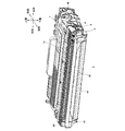
- 4 is a perspective view of the developing cartridge shown in FIG. 1 as seen from the upper right front (developing electrode is not shown).
- FIG. 5 is a cross-sectional view of the developing cartridge shown in FIG.
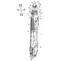
- FIG. 6 is a perspective view of the developer cartridge shown in FIG. 4 as viewed from the upper left rear of the left side wall, the right side wall, and the lower wall of the housing.
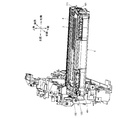
- FIG. 7 is a perspective view of the developing cartridge shown in FIG.
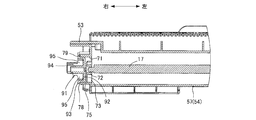
- FIG. 8 is a cross-sectional view when the right end portion of the developing cartridge shown in FIG. 4 is cut along a plane including the central axis of the toner filling port.
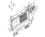
- FIG. 9 is an exploded perspective view of the developing cartridge shown in FIG. 4 as viewed from the front right (developing electrode is not shown), and shows a state where the cap, the supply electrode, and the screw are removed.
- FIG. 10 is an exploded perspective view (development electrode is not shown) of the developing cartridge shown in FIG. 4 as viewed from the upper right front, and shows a state where the supply electrode and the screw are removed.
- FIG. 9 is an exploded perspective view of the developing cartridge shown in FIG. 4 as viewed from the front right (developing electrode is not shown), and shows a state where the cap, the supply electrode, and the screw are removed.
- FIG. 10 is an exploded perspective view (development electrode is not shown) of the developing cartridge shown in FIG. 4 as viewed from the upper right front, and shows a state where the supply electrode and the screw are removed
- FIG. 11 is an exploded perspective view (development electrode is not shown) of the developing cartridge shown in FIG. 4 as viewed from the upper right front, and shows a state where screws are removed.
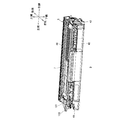
- FIG. 12 is a right side view of the developing cartridge shown in FIG.
- FIG. 13 is a perspective view showing a state in the middle of mounting the process cartridge shown in FIG. 3 in the main casing 2.
- FIG. 14 is a perspective view showing a state in which the process cartridge shown in FIG. 3 is mounted in the main casing 2.
- FIG. 15 is a perspective view showing a state in which the process cartridge shown in FIG. 3 is inserted into a main body casing of a model different from that of a regular laser printer.
- the laser printer 1 includes a main body casing 2.
- a cartridge attaching / detaching port 3 is formed on the front side wall of the main casing 2, and a front cover 4 for opening and closing the cartridge attaching / detaching port 3 is provided.
- the front side of the laser printer 1 is the front side in the front-rear direction. Further, in a state where the laser printer 1 is placed on a plane, the direction perpendicular to the plane is the vertical direction. Then, when the laser printer 1 placed on a plane is viewed from the front side, the left and right sides of the laser printer 1 are defined.
- the process cartridge 5 is mounted at a position slightly ahead of the center in the main body casing 2.
- the process cartridge 5 is mounted in the main body casing 2 via the cartridge attaching / detaching port 3 with the front cover 4 opened, and is detached from the main body casing 2.
- the process cartridge 5 includes a drum cartridge 6 and a developing cartridge 7 that is detachably attached to the drum cartridge 6.
- the drum cartridge 6 includes a drum frame 8.
- a photosensitive drum 9 is rotatably held at the rear end of the drum frame 8.
- the drum frame 8 holds a charger 10 and a transfer roller 11.
- the charger 10 and the transfer roller 11 are disposed behind and below the photosensitive drum 9, respectively.
- a portion of the drum frame 8 in front of the photosensitive drum 9 is a cartridge mounting portion 12.
- the developing cartridge 7 is mounted on the cartridge mounting portion 12.
- the developing cartridge 7 includes a housing 13 that accommodates toner.
- a hopper 14 and a developing chamber 15 communicating with each other are formed adjacent to each other in the front and rear in the housing 13.
- the hopper 14 is a space for storing toner.
- the hopper 14 accommodates an agitator 16 made of a resin film.
- the agitator 16 is attached to an agitator shaft 17 extending in the left-right direction, and is provided so as to be rotatable integrally with the agitator shaft 17. As the agitator 16 rotates, the toner stored in the hopper 14 is agitated and sent from the hopper 14 to the developing chamber 15.
- a developing roller 18 as an example of a developer carrying member and a supply roller 19 as an example of a developer supply member are rotatable about a developing roller shaft 20 and a supply roller shaft 21 that extend in the left-right direction, respectively.
- the developing roller 18 is disposed such that a part of its surface (circumferential surface) is exposed from the rear end of the housing 13.
- the developing cartridge 7 is mounted on the drum cartridge 6 so that the surface of the developing roller 18 is in contact with the surface (circumferential surface) of the photosensitive drum 9.
- the supply roller 19 is disposed such that the surface (circumferential surface) thereof is in contact with the surface of the developing roller 18 from the front lower side.
- the toner in the developing chamber 15 is supplied to the surface of the developing roller 18 by the supply roller 19 and is carried as a thin layer on the surface of the developing roller 18.
- an exposure unit 22 including a laser is disposed above the process cartridge 5.
- the photosensitive drum 9 is rotated at a constant speed clockwise as viewed from the left side. As the photosensitive drum 9 rotates, the surface of the photosensitive drum 9 is uniformly charged by the discharge from the charger 10.
- a laser beam is emitted from the exposure device 22 based on image data received from a personal computer (not shown) connected to the laser printer 1.
- the laser beam passes between the charger 10 and the developing cartridge 7 and is irradiated onto the uniformly positively charged surface of the photosensitive drum 9 to selectively expose the surface of the photosensitive drum 9.
- charges are selectively removed from the exposed portion of the photosensitive drum 9, and an electrostatic latent image is formed on the surface of the photosensitive drum 9.
- toner is supplied from the developing roller 18 to the electrostatic latent image.
- a toner image is formed on the surface of the photosensitive drum 9.
- a paper feed cassette 23 that stores paper P is disposed at the bottom of the main casing 2.
- a pickup roller 24 for feeding paper from the paper feed cassette 23 is provided.
- a S-shaped transport path 25 is formed in a side view.
- the conveyance path 25 reaches from the paper feed cassette 23 to the paper discharge tray 26 formed on the upper surface of the main body casing 2 via the space between the photosensitive drum 9 and the transfer roller 11.
- a separation roller 27 and a separation pad 28 On the transport path 25, a separation roller 27 and a separation pad 28, a pair of paper feed rollers 29, a pair of registration rollers 30, and a pair of paper discharge rollers 31 that face each other are arranged in the transport direction of the paper P. In order.
- the paper P sent out from the paper feed cassette 23 passes between the separation roller 27 and the separation pad 28, and is fed one by one at that time. Thereafter, the paper P is conveyed toward the registration roller 30 by the paper supply roller 29. Then, the sheet P is transported between the photosensitive drum 9 and the transfer roller 11 by the registration roller 30 at an appropriate timing.
- the toner image on the circumferential surface of the photosensitive drum 9 is electrically attracted by the transfer roller 11 when the photosensitive drum 9 rotates and faces the paper P passing between the photosensitive drum 9 and the transfer roller 11. And transferred to the paper P.
- a fixing device 32 is provided on the downstream side in the conveyance direction of the paper P with respect to the transfer roller 11.
- the paper P on which the toner image has been transferred is transported through the transport path 25 and passes through the fixing device 32.
- the toner image becomes an image and is fixed on the paper P by heating and pressing.
- the laser printer 1 has, as operation modes, a single-side mode in which an image (toner image) is formed on one side of the paper P, and the other side opposite to one side of the paper P after an image is formed on one side of the paper P. And a double-sided mode for forming an image.
- the paper P on which an image is formed on one side is discharged onto the paper discharge tray 26 by the paper discharge roller 31.
- a reverse conveyance path 33 is formed in the main casing 2.
- the reverse conveyance path 33 extends from the vicinity of the paper discharge roller 31 between the conveyance path 25 and the paper feed cassette 23, and is connected to a portion of the conveyance path 25 between the paper feed roller 29 and the registration roller 30.
- a pair of first reverse conveyance rollers 34 and a pair of second reverse conveyance rollers 35 are provided on the reverse conveyance path 33.
- the paper P is sent to the reverse conveyance path 33 by the paper discharge roller 31 without being discharged to the paper discharge tray 26. Then, the sheet P is transported through the reverse transport path 33 by the first reverse transport roller 34 and the second reverse transport roller 35, the front and back are reversed, and the other surface on which the image is not formed is the periphery of the photosensitive drum 9. It is fed into the conveyance path 25 in a posture facing the surface. Then, an image is formed on both sides of the paper P by forming an image on the other side of the paper P. The paper P on which images are formed on both sides is discharged onto the paper discharge tray 26 by the paper discharge roller 31. 2.
- the drum frame 8 of the drum cartridge 6 includes a left side wall 41 and a right side wall 42 as shown in FIGS.
- the left side wall 41 and the right side wall 42 have a plate shape extending in the front-rear direction and are opposed to each other with an interval in the left-right direction.
- a front wall 43 is installed between the front end portions of the left side wall 41 and the right side wall 42.
- a rear wall 44 is installed between the rear end portions of the left side wall 41 and the right side wall 42.
- a lower wall 45 is installed between the lower end portions of the left side wall 41 and the right side wall 42.
- an upper wall 46 is installed between the upper ends of the rear end portions of the left side wall 41 and the right side wall 42 so as to cover from above.
- the photosensitive drum 9 and the transfer roller 11 are rotatably supported by the left side wall 41 and the right side wall 42.
- an opening 47 through which the paper P can pass is formed in the lower wall 45 at a position in front of the photosensitive drum 9 and the transfer roller 11.
- an opening 48 through which the paper P can pass is formed in the rear wall 44 at a position facing the contact portion between the photosensitive drum 9 and the transfer roller 11.
- the paper P enters the drum cartridge 6 through the opening 47, passes between the photosensitive drum 9 and the transfer roller 11, and then passes through the opening 48.
- the charger 10 is provided on the upper wall 46.
- an incompatible protrusion 49 protruding leftward is formed at the front end portion of the left side wall 41.
- the incompatible protrusions 49 extend in the vertical direction, bend and extend rearward and downward, and further bend and extend rearward.
- the housing 13 of the developing cartridge 7 is made of resin (for example, polystyrene). As shown in FIG. 4, the housing 13 includes a left side wall 51 as an example of a second side wall and a right side wall 52 as an example of a first side wall that face each other in the left-right direction. Further, as shown in FIG. 5, the housing 13 is installed between the upper wall 53 constructed between the upper ends of the left side wall 51 and the right side wall 52 and between the lower ends of the left side wall 51 and the right side wall 52.
- the lower wall 54 is provided.
- the lower wall 54 extends rearward from the rear end portion of the upper wall 53, faces the developing roller 18 from below, and a supply roller from the front end edge of the tongue portion 55.
- a first curved portion 56 having a semicircular arc cross section extending forward while being curved downward along the circumferential surface of 19;
- the second curved portion 57, the partition wall 58 extending upward from the front end edge (upper edge) of the second curved portion 57, and the staircase so as to be located upward from the middle of the partition wall 58 in the vertical direction.
- a bent portion 59 bent integrally.
- a pair of ribs 60 and 61 facing each other with a minute gap in the front-rear direction are formed in the middle part of the upper wall 53 in the front-rear direction over the entire width in the left-right direction.
- a sealing material (not shown) is provided between the ribs 60 and 61.
- the upper end part of the partition wall part 58 of the lower wall 54 is inserted between the ribs 60 and 61, and is in contact with the sealing material.
- the front end portion of the upper wall 53 is joined to the middle portion in the front-rear direction of the bent portion 59 of the lower wall 54.
- a bent portion 59 behind the joined portion is separated from the upper wall 53.
- a space 62 defined by the left side wall 51, the right side wall 52, the upper wall 53, the partition wall part 58, and the bent part 59 is formed on the front side of the partition wall part 58.
- the hopper 14 and the developing chamber 15 are formed on the rear side of the partition wall portion 58. The hopper 14, the developing chamber 15, and the space 62 are completely isolated by the partition wall portion 58 and the sealing material.
- the partition wall portion 58 may be formed separately from the remaining portion of the lower wall 54. In this case, by removing the partition wall portion 58, the space 62 can be used as a space for storing the toner, so that the capacity of the toner that can be stored in the developing cartridge 7 can be increased. Therefore, using the lower wall 54 formed of the same mold, the small capacity developing cartridge 7 having a relatively small amount of toner and a large amount having a relatively large amount of toner. The capacity developing cartridge 7 can be manufactured.
- a substantially C-shaped (U-shaped) gripping portion 63 opened downward in front view is formed by a central portion in the left-right direction bulging upward.
- the grip portion 63 is gripped by a hand when a user or the like carries the developing cartridge 7. Since the upper wall 53 is joined to the middle portion of the bent portion 59 in the front-rear direction, the rigidity of the bent portion 59 when the grip portion 63 is gripped can be ensured.
- the hopper 14 is a space above the second bending portion 57.
- a toner filling port 71 that is a round hole is formed in a portion of the right side wall 52 that faces the hopper 14.
- an agitator bearing ring 72 and three thin rod-shaped ring support portions 73 are formed in the toner filling port 71 as an example of the developer filling port.
- the agitator bearing ring 72 is provided at the center of the toner filling port 71.
- the ring support 73 is installed between the inner peripheral surface of the toner filling port 71 and the outer peripheral surface of the agitator bearing ring 72, and extends radially at equal angular intervals (120 ° intervals).
- an agitator bearing hole 74 which is a round hole is formed at a position facing the agitator bearing ring 72 in the left-right direction.
- the right end portion and the left end portion of the agitator shaft 17 are rotatably inserted (inserted) into the agitator bearing ring 72 and the agitator bearing hole 74, respectively.
- the agitator shaft 17 (the agitator 16) is provided so as to be rotatable about a rotation axis that coincides with the center line of the toner filling port 71.
- the posture of the agitator 16 can be visually recognized from the outside of the housing 13 through the toner filling port 71. Further, it can be easily confirmed that the agitator shaft 17 is held in the agitator bearing ring 72 and the agitator bearing hole 74.
- a toner filling port 71 is used for filling the hopper 14 with toner. Since the ring support portion 73 has a thin rod shape, a sufficient opening can be secured between the ring support portions 73. Therefore, it is possible to smoothly fill the hopper 14 with toner.
- the cross-sectional shape when cut in the direction orthogonal to the longitudinal direction of the ring support portion 73 is a home base shape that tapers toward the right side. Therefore, when the hopper 14 is filled with toner, the toner is smoothly introduced into the hopper 14 along the tapered cross section of the ring support portion 73. As a result, the hopper 14 can be filled with toner more smoothly.
- the right end of the agitator shaft 17 has a cross shape when viewed from the right side. Therefore, when the right end portion of the agitator shaft 17 is inserted into the agitator bearing ring 72, a gap is generated between the right end portion and the inner peripheral surface of the agitator bearing ring 72. Therefore, the toner can be introduced into the hopper 14 from the gap when the hopper 14 is filled with the toner. As a result, the hopper 14 can be filled with toner more smoothly.
- the agitator bearing hole 74 of the left side wall 51 functions as a hole for removing air when the toner remaining in the hopper 14 is extracted through the toner filling port 71. Therefore, the residual toner can be smoothly extracted from the hopper 14.
- the right wall 52 is formed with a fitted wall portion 75 protruding rightward from the periphery of the toner filling port 71.
- the inner peripheral surface of the fitted wall portion 75 forms a cylindrical surface that is continuous with the inner peripheral surface of the toner filling port 71.
- an engaged portion 76 as an example of a predetermined portion is integrally formed on the outer peripheral portion of the fitted wall portion 75.
- the engaged portion 76 protrudes forward and upward from the fitted wall portion 75.
- the engaged portion 76 is formed with an engaged recessed portion 77 having a circular shape in a side view that is recessed leftward from the right end surface.
- a flange portion 78 is formed integrally with the to-be-fitted wall portion 75 and the to-be-engaged portion 76 so as to project outward from the outer peripheral edge of the to-be-fitted wall portion 75 in the radial direction.
- the flange portion 78 as an example of the attachment portion has a step surface 79 that is recessed by one step with respect to the rightmost end surface of the flange portion 78 by bending the outer peripheral end portion to the right. is doing.
- developing roller bearing holes 81 and 82 are formed through the left side wall 51 and the right side wall 52 at positions above the tongue 55, respectively.
- the developing roller bearing holes 81 and 82 are opened at the rear end edges of the left side wall 51 and the right side wall 52, respectively.
- the left end and the right end of the developing roller shaft 20 are inserted from the rear into the developing roller bearing holes 81 and 82, respectively.
- the developing roller shaft 20 is rotatably supported in the developing roller bearing holes 81 and 82, and both ends thereof. The portion protrudes outward from the left side wall 51 and the right side wall 52.
- supply roller bearing holes 83 and 84 are formed through the left side wall 51 and the right side wall 52 at positions above the first bending portion 56, respectively.
- the supply roller bearing holes 83 and 84 are formed as U-shaped grooves that are opened rearward.
- the left end portion and the right end portion of the supply roller shaft 21 are respectively inserted from the rear, and the supply roller shaft 21 is rotatably supported in the supply roller bearing holes 83 and 84.
- the portion protrudes outward from the left side wall 51 and the right side wall 52.
- the cap 91 is made of the same resin as that of the housing 13, and as shown in FIGS. 8 and 9, a main body 92, an outer peripheral portion 93, a boss 94, and six ribs 95 are integrally formed.
- the cap 91 also has a function of fixing a supply electrode 101 described later.
- the main body portion 92 is a portion that is fitted into the fitted wall portion 75.
- the main body 92 has a U-shaped cross section (angular C-shape) integrally including a cylindrical portion that contacts the inner peripheral surface of the fitted wall portion 75 and a portion that closes the left end surface of the cylindrical portion. I am doing.
- the outer peripheral portion 93 is formed in a flange shape that protrudes from the right end portion of the main body portion 92 to the outside in the radial direction of the main body portion 92, and is welded in contact with the stepped surface 79 of the fitted wall portion 75. Therefore, the boundary between the stepped surface 79 and the outer peripheral portion 93 is not exposed to the outside. Therefore, a tool or the like can be prevented from being inserted into the boundary between the stepped surface 79 and the outer peripheral portion 93, and the cap 91 can be prevented from being carelessly removed from the toner filling port 71. Further, the outer peripheral portion 93 of the cap 91 is welded to the stepped surface 79, whereby the cap 91 is firmly fixed to the fitted wall portion 75. Therefore, the position of the supply electrode 101 fixed to the cap 91 can be kept more stable at a fixed position.
- the outer peripheral portion 93 is formed with an engaging portion 96 corresponding to the engaged portion 76.
- a cylindrical protrusion 97 that fits into the engaged recess 77 is formed.
- the boss 94 as an example of the electrode fixing portion has a substantially cylindrical shape extending rightward from the main body 92 along the central axis of the main body 92 (toner filling port 71). As shown in FIG. 10, the right end portion of the boss 94 has a substantially elliptical (oval) outer shape in which the rotationally symmetric portions of the cylindrical outer peripheral portion are cut out. Thus, the right end portion of the boss 94 has thick portions 98 on both sides of the substantially elliptical long axis direction with respect to the hollow portion, and has thin portions 99 on both sides of the substantially elliptical short axis direction with respect to the hollow portion. ing.
- the developing cartridge 7 is provided with a supply electrode 101 as an example of an electrode for supplying a bias to the supply roller 19.
- the supply electrode 101 is made of a conductive resin.
- the supply electrode 101 includes a crowning portion 102 that is crowned on the right end portion of the supply roller shaft 21, a first extension portion 103 that extends from the crowning portion 102 toward the boss 94 of the cap 91, and the first extension portion 103.
- a substantially elliptical fitting hole 108 corresponding to the outer shape of the right end portion (portion having a substantially elliptical outer shape) of the boss 94 is formed penetrating in the left-right direction.
- the crown portion 102 is crowned to the right end portion of the supply roller shaft 21, the right end portion of the boss 94 is fitted into the fitting hole 108 of the fixed portion 104, and the contact portion 107 contacts the outer peripheral portion 93 of the cap 91.
- the supply electrode 101 is fixed to the cap 91 by screwing a screw 109 as an example of a screwing member into the hollow portion of the boss 94 in the contact state. Even if the supply electrode 101 is formed of a relatively fragile conductive resin, the shaft of the screw 109 is screwed into the hollow portion (screw hole) of the boss 94 of the cap 91, so that the supply electrode 101 is not damaged by the screw 109. Can be prevented.
- the fixed portion 104 is in contact with a step surface that is one step lower than the right end surface of the boss 94.
- the right side surface of the fixed portion 104 is flush with the right end surface of the boss 94.
- the head of the screw 109 is in contact with the right end surface of the boss 94 and the right side surface of the fixed portion 104.
- the supply electrode 101 is arranged so as to overlap with the cap 91 in the left-right direction, and a portion of the supply electrode 101 overlapping the cap 91 is fixed to the cap 91. As a result, at least two positions on the supply electrode 101, that is, two positions of a portion connected to the supply roller shaft 21 and a portion overlapping the cap 91 are fixed. Therefore, the position of the supply electrode 101 can be kept stable.
- the position of the supply electrode 101 can be finely adjusted. By the fine adjustment, the position of the supply electrode 101 can be set to an optimal position. it can. Further, when the supply electrode 101 is damaged, the damaged supply electrode 101 can be easily replaced with a new supply electrode 101.
- the cap 91 can be prevented from being inadvertently removed from the toner filling port 71.
- the supply electrode 101 is formed with a fixed portion 104 that is fixed in a state of being in contact with the boss 94 by a screw 109 and an abutting portion 107 that abuts a portion of the cap 91 different from the boss 94.
- the supply electrode 101 is supported on the cap 91 at two points of the fixed portion 104 and the contact portion 107. Therefore, the position of the supply electrode 101 can be kept more stable.
- the boss 94 has the thick portion 98, the strength of the boss 94 can be ensured.
- the boss 94 has the thin portion 99, even if the head of the screw 109 is small, the head is pushed from the head of the screw 109 to the portion around the fitting hole 108 in the fixed portion 104 without using a washer. Pressure can be applied. Therefore, the screw 109 for fixing the supply electrode 101 can be made common with the screw used for the other part of the developing cartridge 7.
- the cap 91 can be attached to the right side wall 52 so that the boss 94 takes a fixed posture. Since the boss 94 having a substantially elliptical outer shape has a fixed posture, the supply electrode 101 having the substantially elliptical fitting hole 108 can be provided in a fixed posture. As a result, the position of the supply electrode 101 can be kept stable at a certain position.
- the developing cartridge 7 is provided with a developing electrode 111.
- the developing electrode 111 is made of the same conductive resin as the supply electrode 101.
- the developing electrode 111 includes a crowning portion 112 that is crowned at the right end portion of the developing roller shaft 20, an extension portion 113 that extends forward from the crowning portion 112, extends upward and bends upward, and an upper end portion of the extension portion 113.
- a contact portion 114 that is formed and contacts a main body side development electrode (not shown) provided in the main body casing 2 is integrally provided.
- the developing electrode 111 is fixed to the housing 13 by inserting a screw 115 through a bent portion of the extending portion 113 and screwing the screw 115 into a boss 116 (see FIG. 11) protruding from the housing 13. Has been.
- gear cover 121 is attached to the left side surface of the housing 13.
- the gear cover 121 covers almost the entire left side surface of the housing 13.
- gears are attached to the developing roller shaft 20 and the supply roller shaft 21.
- An incompatible protrusion 122 extending leftward is projected from the front end portion of the gear cover 121.
- the process cartridge 5 is inserted into the main casing 2 through the cartridge attaching / detaching port 3, and then the process cartridge 5 is inserted.
- the cartridge can be smoothly moved to the cartridge mounting position shown in FIG.
- the incompatible protrusions 49 and 122 are provided at the front end portions of the drum cartridge 6 and the developing cartridge 7, respectively, when the incompatible protrusions 49 and 122 contact the obstacles 202 and 203, the contact state is changed. It can be confirmed visually.
- the developing cartridge of the present invention is industrially useful because it can stably hold the position of its own electrode, and therefore can provide a good connection with the electrode on the image forming apparatus main body side.
Landscapes
- Physics & Mathematics (AREA)
- General Physics & Mathematics (AREA)
- Dry Development In Electrophotography (AREA)
- Electrophotography Configuration And Component (AREA)
Abstract
電極の位置を安定に保つことができる現像カートリッジである。現像カートリッジ7の筐体13は、左右方向に互いに対向する左側壁51および右側壁52を有している。右側壁52には、キャップ91により閉塞されるトナー充填口が形成されている。また、現像カートリッジ7には、供給ローラにバイアスを供給するための供給電極101が備えられている。供給電極101は、キャップ91と左右方向に重なるように配置されている。そして、供給電極101におけるキャップ91と重なる部分は、ねじ109により、キャップ91に固定されている。
Description
本発明は、レーザプリンタなどの画像形成装置に備えられる現像カートリッジに関する。
レーザプリンタなどの画像形成装置の一例では、感光ドラムを備える感光体カートリッジが本体内に着脱可能に設けられ、現像ローラおよび供給ローラを備える現像カートリッジが感光体カートリッジに装着される。
現像カートリッジ内には、トナーを収容するホッパが形成されている。ホッパ内のトナーは、供給ローラから現像ローラに供給され、感光ドラムおよび現像ローラの回転に伴って、現像ローラから感光ドラムの表面に形成されている静電潜像に供給される。これにより、静電潜像がトナー像に現像される。そして、そのトナー像が用紙に転写されることにより、用紙への画像の形成が達成される。
現像動作のためには、現像ローラおよび供給ローラへのバイアスの供給が必要である。そのため、現像カートリッジには、現像電極および供給電極が設けられている。現像電極および供給電極は、現像カートリッジの側面に配置されて、それぞれ現像ローラおよび供給ローラと電気的に接続されている。現像カートリッジが感光体カートリッジとともに本体内に装着されると、本体内に配置されている電極が現像電極および供給電極に接続されて、現像電極および供給電極にそれぞれバイアスが供給される。
近年、現像カートリッジは、小型化の一途をたどっている。現像カートリッジの小型化により、現像カートリッジの側面における各部材の配置に制約が生じる。たとえば、現像カートリッジの一方の側面には、現像電極および供給電極の他に、ホッパにトナーを充填するための孔を閉塞するキャップが設けられている。現像カートリッジの小型化に伴い、ホッパのサイズも小さくなり、キャップの位置が現像ローラおよび供給ローラに近づく。そのため、現像電極または供給電極とキャップとを並べて配置することが困難となる。
ところが、現像電極または供給電極がキャップとオーバラップして配置されると、そのオーバラップして配置された電極の位置が不安定となり、その電極と本体側の電極との接続不良を生じるおそれがある。
本発明の目的は、電極の位置を安定に保つことができる、現像カートリッジを提供することである。
前記の目的を達成するため、本発明は、所定方向に互いに対向する第1側壁および第2側壁を有し、内部に現像剤を収容する筺体と、前記第1側壁および前記第2側壁に支持され、前記所定方向に延びる回転軸線を中心に回転可能に設けられ、現像剤を担持する現像剤担持部材と、前記第1側壁および前記第2側壁に支持され、前記所定方向に延びる回転軸線を中心に回転可能に設けられ、前記現像剤担持部材に現像剤を供給する現像剤供給部材と、前記第1側壁に形成された現像剤充填口を閉塞するキャップと、前記現像剤担持部材および前記現像剤供給部材の少なくとも一方にバイアスを供給するための電極とを備え、前記電極は、前記キャップと前記所定方向に重なるように配置され、螺合部材により前記キャップに固定されている現像カートリッジを提供している。
現像剤供給部材から現像剤担持部材に現像剤が供給され、その現像剤が現像剤担持部材に担持される。電極は、キャップと所定方向に重なるように配置されており、電極におけるキャップと重なる部分はキャップに固定されているので、電極における少なくとも2箇所の位置、つまり現像剤担持部材および現像剤供給部材の少なくとも一方に接続される部分およびキャップと重なる部分の2箇所の位置が固定される。そのため、電極の位置を安定に保つことができる。
また、キャップに対する電極の固定に、螺合部材が用いられているので、電極の位置の微調整が可能であり、その微調整により、電極の位置を最適な位置にすることができる。また、電極が破損した場合に、その破損した電極を新品の電極と容易に交換することができる。さらに、電極がキャップと重なっているので、キャップが現像剤充填口から不用意に取り外されることを防止できる。
上述の現像カートリッジにおいて、前記キャップには、電極固定部が形成されており、前記電極には、前記螺合部材により前記電極固定部に接触した状態で固定される被固定部と、前記キャップにおける前記電極固定部とは異なる部分に当接する当接部とが形成されている。かかる構成により、電極はキャップ上において被固定部と当接部との2点で支持されることとなり、電極の位置をより安定に保つことができる。
また、前記螺合部材は、ねじであり、前記キャップには、前記所定方向の外側に突出し、前記ねじの軸が挿入されるボスが形成されており、前記電極には、前記ボスが嵌合する嵌合孔が形成されており、前記ボスは、前記ねじの前記軸が挿入される方向と直交する方向の断面において、略楕円形の外形を有している。
電極の嵌合孔を、ボスの外形にあわせた略楕円形とすれば、電極も一定の姿勢に設けることができる。その結果電極の位置を一定の位置で安定に保つことができる。
また、前記キャップには、前記ボスが一定の姿勢をなす状態で前記第1側壁の所定部と係合する係合部が形成されている。 係合部を所定部と係合させることで、ボスが一定の姿勢をなすようにキャップを右側壁に取り付けることができる。
また、前記電極は導電性樹脂からなり、前記螺合部材はねじであり、前記ねじの軸は前記キャップにねじ込まれている。ねじは電極ではなくボスに螺合するので、比較的脆い導電性樹脂で電極を形成したとしても、電極の破損を防止できる。
また、前記第1側壁における前記現像剤充填口の周囲には、前記キャップが取り付けられる取付部が形成されており、前記取付部には、その最外端面よりも前記所定方向の内側に一段下がった段差面が形成されており、前記キャップは、その外周部が前記段差面に当接している。
そのために、段差面と外周部との境界が外部に露出せず、段差面と外周部との境界に工具などが差し込まれることを防止でき、キャップがトナー充填口から不用意に取り外されることを防止できる。
以下では、本発明の実施の形態について、添付図面を参照しつつ詳細に説明する。
1.レーザプリンタ
図1に示されるように、レーザプリンタ1は、本体ケーシング2を備えている。本体ケーシング2の正面側の側壁には、カートリッジ着脱口3が形成され、このカートリッジ着脱口3を開閉するフロントカバー4が設けられている。
1.レーザプリンタ
図1に示されるように、レーザプリンタ1は、本体ケーシング2を備えている。本体ケーシング2の正面側の側壁には、カートリッジ着脱口3が形成され、このカートリッジ着脱口3を開閉するフロントカバー4が設けられている。
なお、レーザプリンタ1の正面側は、前後方向における前側である。また、レーザプリンタ1が平面上に載置された状態で、その平面に直交する方向が上下方向である。そして、平面上に載置されたレーザプリンタ1を前側から見て、レーザプリンタ1の左右を規定する。
本体ケーシング2内の中央より少し前側の位置には、プロセスカートリッジ5が装着されている。プロセスカートリッジ5は、フロントカバー4を開いた状態で、カートリッジ着脱口3を介して、本体ケーシング2内に装着され、また、本体ケーシング2内から離脱される。
プロセスカートリッジ5は、ドラムカートリッジ6と、そのドラムカートリッジ6に着脱自在に装着される現像カートリッジ7とからなる。
ドラムカートリッジ6は、ドラムフレーム8を備えている。ドラムフレーム8の後端部には、感光ドラム9が回転可能に保持されている。また、ドラムフレーム8には、帯電器10および転写ローラ11が保持されている。帯電器10および転写ローラ11は、それぞれ感光ドラム9の後方および下方に配置されている。
ドラムフレーム8における感光ドラム9よりも前側の部分は、カートリッジ装着部12とされている。現像カートリッジ7は、カートリッジ装着部12に装着される。
現像カートリッジ7は、トナーを収容する筐体13を備えている。筐体13の内部には、互いに連通するホッパ14および現像室15が前後に隣接して形成されている。
ホッパ14は、トナーを収容するための空間である。ホッパ14には、樹脂フィルムからなるアジテータ16が収容されている。アジテータ16は、左右方向に延びるアジテータ軸17に貼り付けられ、アジテータ軸17と一体的に回転可能に設けられている。アジテータ16の回転により、ホッパ14内に収容されているトナーが攪拌されつつ、ホッパ14から現像室15へ送られる。
現像室15には、現像剤担持部材の一例としての現像ローラ18および現像剤供給部材の一例としての供給ローラ19がそれぞれ左右方向に延びる現像ローラ軸20および供給ローラ軸21を中心に回転可能に設けられている。現像ローラ18は、その表面(周面)の一部が筐体13の後端部から露出するように配置されている。現像カートリッジ7は、現像ローラ18の表面が感光ドラム9の表面(周面)と接触するように、ドラムカートリッジ6に装着される。供給ローラ19は、その表面(周面)が現像ローラ18の表面に対して前下方から接触するように配置されている。現像室15内のトナーは、供給ローラ19により現像ローラ18の表面に供給され、現像ローラ18の表面上に薄層となって担持される。
また、本体ケーシング2内には、プロセスカートリッジ5の上方に、レーザなどを備える露光器22が配置されている。
画像形成時には、感光ドラム9が左側から見て時計回りに一定速度で回転される。感光ドラム9の回転に伴って、感光ドラム9の表面は、帯電器10からの放電により、一様に帯電される。一方、レーザプリンタ1に接続されたパーソナルコンピュータ(図示せず)から受信する画像データに基づいて、露光器22からレーザビームが出射される。レーザビームは、帯電器10と現像カートリッジ7との間を通り、一様に正帯電された感光ドラム9の表面に照射され、感光ドラム9の表面を選択的に露光する。これにより、感光ドラム9の露光された部分から電荷が選択的に除去され、感光ドラム9の表面に静電潜像が形成される。感光ドラム9の回転により、静電潜像が現像ローラ18に対向すると、現像ローラ18から静電潜像にトナーが供給される。これによって、感光ドラム9の表面にトナー像が形成される。
本体ケーシング2の底部には、用紙Pを収容する給紙カセット23が配置されている。給紙カセット23の上方には、給紙カセット23から用紙を送り出すためのピックアップローラ24が設けられている。
また、本体ケーシング2内には、側面視S字状の搬送路25が形成されている。この搬送路25は、給紙カセット23から感光ドラム9と転写ローラ11との間を経由して、本体ケーシング2の上面に形成された排紙トレイ26に至る。搬送路25上には、互いに対向配置される分離ローラ27および分離パッド28、1対の給紙ローラ29、1対のレジストローラ30ならびに1対の排紙ローラ31が用紙Pの搬送方向にこの順で設けられている。
給紙カセット23から送り出された用紙Pは、分離ローラ27と分離パッド28との間を通過し、その際に1枚ずつに捌かれる。その後、用紙Pは、給紙ローラ29により、レジストローラ30に向けて搬送される。そして、その用紙Pは、レジストローラ30により、適切なタイミングで、感光ドラム9と転写ローラ11との間に向けて搬送される。
感光ドラム9の周面上のトナー像は、感光ドラム9の回転により、感光ドラム9と転写ローラ11との間を通過する用紙Pと対向したときに、転写ローラ11により電気的に引き寄せられて、用紙Pに転写される。
搬送路25上には、転写ローラ11に対して用紙Pの搬送方向の下流側に、定着器32が設けられている。トナー像が転写された用紙Pは、搬送路25を搬送されて、定着器32を通過する。定着器32では、加熱および加圧により、トナー像が画像となって用紙Pに定着される。
このレーザプリンタ1は、動作モードとして、用紙Pの片面に画像(トナー像)を形成する片面モードと、用紙Pの一方面に画像を形成した後、その用紙Pの一方面と反対の他方面に画像を形成する両面モードとを有している。
片面モードでは、一方面に画像が形成された用紙Pは、排紙ローラ31により、排紙トレイ26上に排出される。
両面モードを実現するための構成として、本体ケーシング2内には、反転搬送路33が形成されている。反転搬送路33は、排紙ローラ31の近傍から搬送路25と給紙カセット23との間を延び、搬送路25における給紙ローラ29とレジストローラ30との間の部分に接続されている。反転搬送路33上には、1対の第1反転搬送ローラ34および1対の第2反転搬送ローラ35が設けられている。
両面モードでは、用紙Pの一方面に画像が形成された後、その用紙Pは、排紙ローラ31により、排紙トレイ26に排出されずに、反転搬送路33に送り込まれる。そして、用紙Pは、第1反転搬送ローラ34および第2反転搬送ローラ35により、反転搬送路33を搬送され、その表裏が反転されて、画像が形成されていない他方面が感光ドラム9の周面と対向する姿勢で搬送路25に送り込まれる。そして、用紙Pの他方面に画像が形成されることにより、用紙Pの両面への画像の形成が達成される。両面に画像が形成された用紙Pは、排紙ローラ31により、排紙トレイ26上に排出される。
2.ドラムカートリッジ
ドラムカートリッジ6のドラムフレーム8は、図2,3に示されるように、左側壁41および右側壁42を備えている。左側壁41および右側壁42は、前後方向に長く延びる板状をなし、左右方向に間隔を空けて対向している。左側壁41および右側壁42の各前端部間には、前壁43が架設されている。左側壁41および右側壁42の各後端部間には、後壁44が架設されている。左側壁41および右側壁42の各下端部間には、図1に示されるように、下壁45が架設されている。左側壁41および右側壁42の各後端部の上端部間には、図2,3に示されるように、上壁46が上方から覆い被さるように架設されている。
2.ドラムカートリッジ
ドラムカートリッジ6のドラムフレーム8は、図2,3に示されるように、左側壁41および右側壁42を備えている。左側壁41および右側壁42は、前後方向に長く延びる板状をなし、左右方向に間隔を空けて対向している。左側壁41および右側壁42の各前端部間には、前壁43が架設されている。左側壁41および右側壁42の各後端部間には、後壁44が架設されている。左側壁41および右側壁42の各下端部間には、図1に示されるように、下壁45が架設されている。左側壁41および右側壁42の各後端部の上端部間には、図2,3に示されるように、上壁46が上方から覆い被さるように架設されている。
上壁46と下壁45との間において、感光ドラム9および転写ローラ11が左側壁41および右側壁42に回転可能に支持されている。下壁45には、図1に示されるように、感光ドラム9および転写ローラ11よりも前方の位置に、用紙Pが通過可能な開口47が形成されている。また、後壁44には、感光ドラム9と転写ローラ11との接触部分に対向する位置に、用紙Pが通過可能な開口48が形成されている。用紙Pは、開口47からドラムカートリッジ6内に進入し、感光ドラム9と転写ローラ11との間を通過した後、開口48を通過する。図1,2に示されるように、上壁46に、帯電器10が設けられている。
また、図2に示されるように、左側壁41の前端部には、左方に突出する非互換突起49が形成されている。非互換突起49は、上下方向に延び、後下方に屈曲して延び、さらに後方に屈曲して延びる形状をなしている。
3.現像カートリッジ
(1)筐体
現像カートリッジ7の筐体13は、樹脂(たとえば、ポリスチレン)からなる。筐体13は、図4に示されるように、左右方向に互いに対向する第2側壁の一例としての左側壁51および第1側壁の一例としての右側壁52を備えている。また、筐体13は、図5に示されるように、左側壁51および右側壁52の各上端部間に架設される上壁53と、左側壁51および右側壁52の各下端部間に架設される下壁54とを備えている。
(1)筐体
現像カートリッジ7の筐体13は、樹脂(たとえば、ポリスチレン)からなる。筐体13は、図4に示されるように、左右方向に互いに対向する第2側壁の一例としての左側壁51および第1側壁の一例としての右側壁52を備えている。また、筐体13は、図5に示されるように、左側壁51および右側壁52の各上端部間に架設される上壁53と、左側壁51および右側壁52の各下端部間に架設される下壁54とを備えている。
下壁54は、図5,6に示されるように、上壁53の後端部よりも後方に延び、現像ローラ18に下方から対向する舌部55と、舌部55の前端縁から供給ローラ19の周面に沿って下方に凸湾曲しつつ前方に延びる断面半円弧状の第1湾曲部56と、第1湾曲部56の前端縁から下方に凸湾曲しつつ前方に延びる断面半円弧状の第2湾曲部57と、第2湾曲部57の前端縁(上端縁)から上方に延びる仕切壁部58と、仕切壁部58の上下方向の途中部から前方ほど上方に位置するように階段状に屈曲した屈曲部59とを一体的に有している。
上壁53の前後方向の途中部には、前後方向に微小な間隔を空けて対向する1対のリブ60,61が左右方向の全幅にわたって形成されている。リブ60,61間には、シール材(図示せず)が設けられている。そして、下壁54の仕切壁部58の上端部は、リブ60,61間に差し込まれて、シール材に当接している。また、上壁53の前端部は、下壁54の屈曲部59の前後方向の途中部に接合されている。この接合している部分よりも後方の屈曲部分59は上壁53から離間している。これにより、仕切壁部58の前側には、左側壁51、右側壁52、上壁53、仕切壁部58および屈曲部59により区画される空間62が形成されている。一方、仕切壁部58の後側には、ホッパ14および現像室15が形成されている。ホッパ14および現像室15と空間62とは、仕切壁部58およびシール材により完全に隔離されている。
なお、仕切壁部58が下壁54の残余の部分と別体に形成されていてもよい。この場合、仕切壁部58を取り外すことにより、トナーを収容するスペースとして空間62を使用できるので、現像カートリッジ7に収容可能なトナーの容量を増大させることができる。そのため、同じ金型で形成される下壁54を用いて、トナーの収容量が相対的に小容量である小容量用の現像カートリッジ7と、トナーの収容量が相対的に大容量である大容量用の現像カートリッジ7とを製造することができる。
屈曲部59の前端部には、左右方向の中央部が上方に膨出することにより、正面視で下方に開放された略C字状(コ字状)の把持部63が形成されている。把持部63は、ユーザなどが現像カートリッジ7を持ち運ぶ際に手で把持される。屈曲部59の前後方向の途中部に上壁53が接合されているので、把持部63が把持されたときの屈曲部59の剛性を確保することができる。ホッパ14は、第2湾曲部57の上方の空間である。
図6に示されるように、右側壁52におけるホッパ14に臨む部分には、丸孔であるトナー充填口71が形成されている。現像剤充填口の一例としてのトナー充填口71内には、図7に示されるように、アジテータ軸受リング72および3本の細い棒状のリング支持部73が形成されている。アジテータ軸受リング72は、トナー充填口71の中心部に設けられている。リング支持部73は、トナー充填口71の内周面とアジテータ軸受リング72の外周面との間に架設され、等角度間隔(120°間隔)で放射状に延びている。
左側壁51には、アジテータ軸受リング72と左右方向に対向する位置に、丸孔であるアジテータ軸受孔74が形成されている。
そして、図6~8に示されるように、アジテータ軸受リング72およびアジテータ軸受孔74には、それぞれアジテータ軸17の右端部および左端部が回転可能に挿通(挿入)されている。これにより、アジテータ軸17(アジテータ16)は、トナー充填口71の中心線と一致する回転軸線を中心に回転可能に設けられている。
そのため、筐体13の外部からトナー充填口71を通してアジテータ16の姿勢を視認することができる。また、アジテータ軸17がアジテータ軸受リング72およびアジテータ軸受孔74に保持されていることを容易に確認することができる。
ホッパ14へのトナーの充填には、トナー充填口71が使用される。リング支持部73が細い棒状をなしているので、各リング支持部73の間に十分な開口を確保することができる。よって、ホッパ14にトナーをスムーズに充填することができる。
また、図7に示されるように、リング支持部73の長手方向と直交する方向に切断したときの断面形状は、右側に向かって先細りとなるホームベース形状をなしている。そのため、ホッパ14へのトナーの充填の際に、トナーがリング支持部73の断面先細り形状に沿ってホッパ14にスムーズに導入される。その結果、ホッパ14にトナーを一層スムーズに充填することができる。
さらに、アジテータ軸17の右端部は、右側面視で十字状をなしている。そのため、アジテータ軸17の右端部がアジテータ軸受リング72に挿通された状態において、その右端部とアジテータ軸受リング72の内周面との間に隙間が生じる。よって、ホッパ14へのトナーの充填の際に、その隙間からもトナーをホッパ14に導入することができる。その結果、ホッパ14にトナーをより一層スムーズに充填することができる。
また、左側壁51のアジテータ軸受孔74は、ホッパ14に残留するトナーがトナー充填口71を介して抜き取られるときに、空気抜きのための孔として機能する。そのため、ホッパ14から残留トナーをスムーズに抜き取ることができる。
右側壁52には、図7,8に示されるように、トナー充填口71の周囲から右方に突出する被嵌合壁部75が形成されている。被嵌合壁部75の内周面は、トナー充填口71の内周面に連続する円筒面をなしている。被嵌合壁部75の外周部には、図7に示されるように、所定部の一例としての被係合部76が一体的に形成されている。被係合部76は、被嵌合壁部75から前上方に突出している。被係合部76には、右端面から左方に凹む側面視円形の被係合凹部77が形成されている。そして、被嵌合壁部75および被係合部76と一体的に、それらの外周縁から被嵌合壁部75の径方向の外側に張り出すフランジ部78が形成されている。取付部の一例としてのフランジ部78は、図8に示されるように、その外周端部が右方に屈曲することにより、フランジ部78の最右端面に対して一段凹んだ段差面79を有している。
左側壁51および右側壁52には、図6に示されるように、舌部55の上方の位置に、それぞれ現像ローラ軸受孔81,82が貫通して形成されている。現像ローラ軸受孔81,82は、それぞれ左側壁51および右側壁52の後端縁において開放されている。現像ローラ軸受孔81,82には、それぞれ現像ローラ軸20の左端部および右端部が後方から差し入れられ、現像ローラ軸20は、現像ローラ軸受孔81,82内において回転可能に支持され、その両端部が左側壁51および右側壁52の外方に突出している。
また、左側壁51および右側壁52には、第1湾曲部56の上方の位置に、それぞれ供給ローラ軸受孔83,84が貫通して形成されている。供給ローラ軸受孔83,84は、後方に開放される側面視U字状の溝として形成されている。供給ローラ軸受孔83,84には、それぞれ供給ローラ軸21の左端部および右端部が後方から差し入れられ、供給ローラ軸21は、供給ローラ軸受孔83,84内において回転可能に支持され、その両端部が左側壁51および右側壁52の外方に突出している。
(2)キャップ
図8に示されるように、筐体13の被嵌合壁部75にはキャップ91が嵌合されている。このキャップ91により、トナー充填口71が閉塞されている。キャップ91は、筐体13と同じ樹脂からなり、図8,9に示されるように、本体部92、外周部93、ボス94および6個のリブ95が一体的に形成されている。キャップ91は後述する供給電極101を固定する機能も有している。
(2)キャップ
図8に示されるように、筐体13の被嵌合壁部75にはキャップ91が嵌合されている。このキャップ91により、トナー充填口71が閉塞されている。キャップ91は、筐体13と同じ樹脂からなり、図8,9に示されるように、本体部92、外周部93、ボス94および6個のリブ95が一体的に形成されている。キャップ91は後述する供給電極101を固定する機能も有している。
本体部92は、被嵌合壁部75に内嵌される部分である。本体部92は、被嵌合壁部75の内周面に接する円筒状の部分およびその円筒状の部分の左端面を閉塞する部分を一体的に有する断面コ字状(角張ったC字状)をなしている。
外周部93は、本体部92の右端部から本体部92の径方向の外側に張り出すフランジ状に形成され、被嵌合壁部75の段差面79に当接して溶着されている。そのため、段差面79と外周部93との境界が外部に露出しない。よって、段差面79と外周部93との境界に工具などが差し込まれることを防止でき、キャップ91がトナー充填口71から不用意に取り外されることを防止できる。また、キャップ91の外周部93が段差面79に溶着されることにより、キャップ91が被嵌合壁部75に対して強固に固定されている。そのため、キャップ91に固定される供給電極101の位置を一定の位置で一層安定に保つことができる。
外周部93には、図9に示されるように、被係合部76に対応して、係合部96が形成されている。係合部96の左端面には、被係合凹部77に嵌合する円柱状の突起97が形成されている。被係合凹部77に突起97が嵌合することにより、キャップ91が被嵌合壁部75に対してトナー充填口71の周方向に位置決めされている。
電極固定部の一例としてのボス94は、本体部92(トナー充填口71)の中心軸線に沿って、本体部92から右方に延びる略円筒状をなしている。ボス94の右端部は、図10に示されるように、その円筒状の外周部における互いに回転対称をなす部分が切除された略楕円形(小判形)の外形を有している。これにより、ボス94の右端部は、中空部分に対する略楕円形の長軸方向の両側に肉厚部98を有し、中空部分に対する略楕円形の短軸方向の両側に肉薄部99を有している。
6個のリブ95は、ボス94の外周面から本体部92に向けて延びる放射状に形成されている。
(3)電極
図9~11に示されるように、現像カートリッジ7には、供給ローラ19にバイアスを供給するための電極の一例としての供給電極101が設けられている。供給電極101は、導電性樹脂からなる。供給電極101は、供給ローラ軸21の右端部に冠着される冠着部102と、冠着部102からキャップ91のボス94に向けて延びる第1延部103と、第1延部103の先端部に形成され、ボス94に固定される被固定部104と、被固定部104から上方に延びる第2延部105と、第2延部105の上端部に形成され、本体ケーシング2内に設けられる本体側供給電極(図示せず)が当接する接点部106と、第2延部105の左側面(裏面)に突設され、キャップ91の外周部93に当接する当接部107(図9参照)とを一体的に有している。
(3)電極
図9~11に示されるように、現像カートリッジ7には、供給ローラ19にバイアスを供給するための電極の一例としての供給電極101が設けられている。供給電極101は、導電性樹脂からなる。供給電極101は、供給ローラ軸21の右端部に冠着される冠着部102と、冠着部102からキャップ91のボス94に向けて延びる第1延部103と、第1延部103の先端部に形成され、ボス94に固定される被固定部104と、被固定部104から上方に延びる第2延部105と、第2延部105の上端部に形成され、本体ケーシング2内に設けられる本体側供給電極(図示せず)が当接する接点部106と、第2延部105の左側面(裏面)に突設され、キャップ91の外周部93に当接する当接部107(図9参照)とを一体的に有している。
被固定部104には、ボス94の右端部(略楕円形の外形を有する部分)の外形に対応した略楕円形の嵌合孔108が左右方向に貫通して形成されている。
冠着部102が供給ローラ軸21の右端部に冠着され、被固定部104の嵌合孔108にボス94の右端部が嵌合され、当接部107がキャップ91の外周部93に当接した状態で、螺合部材の一例としてのねじ109がボス94の中空部分にねじ込まれることにより、供給電極101はキャップ91に固定されている。供給電極101が比較的脆い導電性樹脂から形成されていたとしても、ねじ109の軸は、キャップ91のボス94の中空部分(ねじ穴)にねじ込まれるので、ねじ109による供給電極101の破損を防止することができる。
被固定部104は、ボス94の右端面に対して一段下がった段差面に当接している。被固定部104の右側面は、ボス94の右端面と面一をなしている。そして、ねじ109の頭は、ボス94の右端面および被固定部104の右側面に跨がって接触している。
供給電極101は、キャップ91と左右方向に重なるように配置されており、供給電極101におけるキャップ91と重なる部分は、キャップ91に固定されている。これにより、供給電極101における少なくとも2箇所の位置、つまり供給ローラ軸21に接続される部分およびキャップ91と重なる部分の2箇所の位置が固定される。そのため、供給電極101の位置を安定に保つことができる。
キャップ91に対する供給電極101の固定に、ねじ109が用いられているので、供給電極101の位置の微調整が可能であり、その微調整により、供給電極101の位置を最適な位置にすることができる。また、供給電極101が破損した場合に、その破損した供給電極101を新品の供給電極101と容易に交換することができる。
さらに、供給電極101がキャップ91と重なっているので、キャップ91がトナー充填口71から不用意に取り外されることを防止できる。
また、供給電極101には、ねじ109によりボス94に接触した状態で固定される被固定部104と、キャップ91におけるボス94とは異なる部分に当接する当接部107とが形成されているので、供給電極101は、キャップ91上において被固定部104と当接部107との2点で支持される。そのため、供給電極101の位置をより安定に保つことができる。
また、ボス94が肉厚部98を有することにより、ボス94の強度を確保することができる。その一方で、ボス94が肉薄部99を有することにより、ねじ109の頭が小さくても、ワッシャを用いることなく、ねじ109の頭から被固定部104における嵌合孔108の周囲の部分に押圧力を加えることができる。そのため、供給電極101の固定のためのねじ109を現像カートリッジ7の他の部分に使用されるねじと共通にすることができる。
また、係合部96を被係合部76と係合させることにより、ボス94が一定の姿勢をなすように、キャップ91を右側壁52に取り付けることができる。外形が略楕円形のボス94が一定の姿勢をなすので、略楕円形の嵌合孔108を有する供給電極101を一定の姿勢に設けることができる。その結果、供給電極101の位置を一定の位置で安定に保つことができる。
図12に示されるように、現像カートリッジ7には、現像電極111が設けられている。現像電極111は、供給電極101と同じ導電性樹脂からなる。現像電極111は、現像ローラ軸20の右端部に冠着される冠着部112と、冠着部112から前方に延び、上方に屈曲して延びる延部113と、延部113の上端部に形成され、本体ケーシング2内に設けられる本体側現像電極(図示せず)が当接する接点部114とを一体的に有している。現像電極111は、延部113の屈曲した部分にねじ115が挿通され、ねじ115が筐体13に突設されたボス116(図11参照)にねじ込まれることにより、筐体13に対して固定されている。
(4)ギヤカバー
図4に示されるように、筐体13の左側面には、ギヤカバー121が取り付けられている。ギヤカバー121は、筐体13の左側面のほぼ全体を覆っている。ギヤカバー121の内側において、現像ローラ軸20および供給ローラ軸21などにギヤが取り付けられている。ギヤカバー121の前端部には、左方に延びる非互換突起122が突設されている。
図4に示されるように、筐体13の左側面には、ギヤカバー121が取り付けられている。ギヤカバー121は、筐体13の左側面のほぼ全体を覆っている。ギヤカバー121の内側において、現像ローラ軸20および供給ローラ軸21などにギヤが取り付けられている。ギヤカバー121の前端部には、左方に延びる非互換突起122が突設されている。
4.本体ケーシング内へのプロセスカートリッジの装着
図13,14に示されるように、本体ケーシング2(図1参照)内において、本体ケーシング2内に対するプロセスカートリッジ5の着脱時にドラムカートリッジ6の非互換突起49および現像カートリッジ7の非互換突起122がそれぞれ通過する領域131,132は、空間とされている。すなわち、本体ケーシング2内に対するプロセスカートリッジ5の着脱時に非互換突起49,122が通過する領域には、何らの部材も設けられていない。
図13,14に示されるように、本体ケーシング2(図1参照)内において、本体ケーシング2内に対するプロセスカートリッジ5の着脱時にドラムカートリッジ6の非互換突起49および現像カートリッジ7の非互換突起122がそれぞれ通過する領域131,132は、空間とされている。すなわち、本体ケーシング2内に対するプロセスカートリッジ5の着脱時に非互換突起49,122が通過する領域には、何らの部材も設けられていない。
したがって、フロントカバー4(図1参照)が開かれた状態で、図13に示されるように、プロセスカートリッジ5をカートリッジ着脱口3を介して本体ケーシング2内に差し入れた後、そのプロセスカートリッジ5を図14に示されるカートリッジ装着位置までスムーズに移動させることができる。
一方、図15に示されるように、レーザプリンタ1とは異なる機種の本体ケーシング201内にプロセスカートリッジ5が差し入れられた場合、プロセスカートリッジ5が後方に移動されると、その移動の途中で非互換突起49が本体ケーシング2内の障害物202に当接するか、および/または、非互換突起122が本体ケーシング2内の障害物203に当接し、それ以上のプロセスカートリッジ5の移動が阻止される。よって、プロセスカートリッジ5が本体ケーシング201内に誤装着されることを防止できる。また、非互換突起49,122がそれぞれドラムカートリッジ6および現像カートリッジ7の前端部に設けられているので、非互換突起49,122が障害物202,203に当接した時に、その当接状態を目視で確認することができる。
本発明の現像カートリッジは、自身の電極の位置を安定して保持でき、そのため画像形成装置本体側の電極との接続を良好に提供できるので、産業上有用である。
7 現像カートリッジ
13 筐体
18 現像ローラ
19 供給ローラ
51 左側壁
52 右側壁
71 トナー充填口
76 被係合部
79 段差面
91 キャップ
94 ボス
96 係合部
101 供給電極
104 被固定部
107 当接部
108 嵌合孔
109 ねじ
13 筐体
18 現像ローラ
19 供給ローラ
51 左側壁
52 右側壁
71 トナー充填口
76 被係合部
79 段差面
91 キャップ
94 ボス
96 係合部
101 供給電極
104 被固定部
107 当接部
108 嵌合孔
109 ねじ
Claims (6)
- 現像剤充填口(71)が形成された第1側壁(52)と、該第1側壁(52)に所定方向で対向する第2側壁(51)とを有し、内部に現像剤を収容する筺体(13)と、
前記第1側壁(52)および前記第2側壁(51)に支持され、前記所定方向に延びる回転軸線を中心に回転可能に設けられ、現像剤を担持する現像剤担持部材(18)と、
前記第1側壁(52)および前記第2側壁(51)に支持され、前記所定方向に延びる回転軸線を中心に回転可能に設けられ、前記現像剤担持部材(18)に現像剤を供給する現像剤供給部材(19)と、
前記現像剤充填口(71)を閉塞するキャップ(91)と、
前記現像剤担持部材(18)および前記現像剤供給部材(19)の少なくとも一方にバイアスを供給するための電極(101)と、
前記電極(101)を前記キャップに固定する螺合部材(109)と、を有し、
前記電極(101)は前記キャップ(91)と前記所定方向に重なるように配置されて、前記螺合部材(109)により前記キャップ(91)に固定されている、現像カートリッジ。 - 前記キャップ(91)には、電極固定部(94)が形成されており、
前記電極(101)には、前記螺合部材(109)により前記電極固定部(94)に接触した状態で固定される被固定部(104)と、前記キャップ(91)における前記電極固定部(94)とは異なる部分に当接する当接部(107)とが形成されている、請求項1に記載の現像カートリッジ。 - 前記螺合部材(109)は、ねじであり、
前記キャップ(91)には、前記所定方向の外側に突出し、前記ねじ(109)の軸が挿入されるボス(94)が形成されており、
前記電極(101)には、前記ボス(94)が嵌合する嵌合孔(108)が形成されており、
前記ボス(94)は、前記ねじ(109)の前記軸が挿入される方向と直交する方向の断面において、略楕円形の外形を有している、請求項1に記載の現像カートリッジ。 - 前記キャップ(91)には、前記ボス(94)が一定の姿勢をなす状態で前記第1側壁(52)の所定部(76)と係合する係合部(96)が形成されている、請求項3に記載の現像カートリッジ。
- 前記電極(101)は、導電性樹脂からなり、
前記螺合部材(109)は、ねじであり、
前記ねじ(109)の軸は、前記キャップ(91)にねじ込まれる、請求項1に記載の現像カートリッジ。 - 前記第1側壁(52)における前記現像剤充填口(71)の周囲には、前記キャップ(91)が取り付けられる取付部(78)が形成されており、
前記取付部(78)には、その最外端面よりも前記所定方向の内側に一段下がった段差面(79)が形成されており、
前記キャップ(91)は、その外周部(93)が前記段差面(79)に当接している、請求項1~5のいずれか一項に記載の現像カートリッジ。
Priority Applications (1)
| Application Number | Priority Date | Filing Date | Title |
|---|---|---|---|
| US13/928,465 US9316991B2 (en) | 2010-12-27 | 2013-06-27 | Developer cartridge |
Applications Claiming Priority (2)
| Application Number | Priority Date | Filing Date | Title |
|---|---|---|---|
| JP2010290486A JP5299419B2 (ja) | 2010-12-27 | 2010-12-27 | 現像カートリッジ |
| JP2010-290486 | 2010-12-27 |
Related Child Applications (1)
| Application Number | Title | Priority Date | Filing Date |
|---|---|---|---|
| US13/928,465 Continuation-In-Part US9316991B2 (en) | 2010-12-27 | 2013-06-27 | Developer cartridge |
Publications (1)
| Publication Number | Publication Date |
|---|---|
| WO2012090907A1 true WO2012090907A1 (ja) | 2012-07-05 |
Family
ID=46383011
Family Applications (1)
| Application Number | Title | Priority Date | Filing Date |
|---|---|---|---|
| PCT/JP2011/080014 Ceased WO2012090907A1 (ja) | 2010-12-27 | 2011-12-26 | 現像カートリッジ |
Country Status (4)
| Country | Link |
|---|---|
| US (1) | US9316991B2 (ja) |
| JP (1) | JP5299419B2 (ja) |
| CN (1) | CN202472243U (ja) |
| WO (1) | WO2012090907A1 (ja) |
Cited By (5)
| Publication number | Priority date | Publication date | Assignee | Title |
|---|---|---|---|---|
| WO2014010114A1 (ja) * | 2012-07-09 | 2014-01-16 | ブラザー工業株式会社 | カートリッジ |
| WO2014010129A1 (ja) * | 2012-07-09 | 2014-01-16 | ブラザー工業株式会社 | プロセスカートリッジおよび画像形成装置 |
| WO2014010118A1 (ja) * | 2012-07-09 | 2014-01-16 | ブラザー工業株式会社 | 現像装置 |
| CN110161819A (zh) * | 2012-07-09 | 2019-08-23 | 兄弟工业株式会社 | 显影盒 |
| US11150573B2 (en) | 2012-07-09 | 2021-10-19 | Brother Kogoyo Kabushiki Kaisha | Developing cartridge having electrode |
Families Citing this family (13)
| Publication number | Priority date | Publication date | Assignee | Title |
|---|---|---|---|---|
| JP5299419B2 (ja) * | 2010-12-27 | 2013-09-25 | ブラザー工業株式会社 | 現像カートリッジ |
| JP6031912B2 (ja) * | 2012-09-21 | 2016-11-24 | ブラザー工業株式会社 | カートリッジ、および、カートリッジの製造方法 |
| JP6056406B2 (ja) * | 2012-11-20 | 2017-01-11 | ブラザー工業株式会社 | カートリッジおよびカートリッジの製造方法 |
| JP6127918B2 (ja) * | 2013-10-31 | 2017-05-17 | ブラザー工業株式会社 | 現像装置 |
| JP6194797B2 (ja) * | 2014-01-06 | 2017-09-13 | ブラザー工業株式会社 | 現像カートリッジ |
| JP6379855B2 (ja) * | 2014-08-25 | 2018-08-29 | ブラザー工業株式会社 | 現像カートリッジ |
| JP6387844B2 (ja) * | 2015-01-30 | 2018-09-12 | ブラザー工業株式会社 | 現像カートリッジ |
| JP6439468B2 (ja) * | 2015-01-30 | 2018-12-19 | ブラザー工業株式会社 | 現像カートリッジ |
| USD795340S1 (en) * | 2015-10-15 | 2017-08-22 | Brother Industries, Ltd. | Toner cartridge |
| JP6604197B2 (ja) * | 2015-12-25 | 2019-11-13 | ブラザー工業株式会社 | 現像カートリッジ |
| JP6206530B2 (ja) | 2016-03-31 | 2017-10-04 | ブラザー工業株式会社 | トナーカートリッジ |
| JP6693302B2 (ja) * | 2016-06-30 | 2020-05-13 | ブラザー工業株式会社 | 現像カートリッジ |
| JP6821979B2 (ja) * | 2016-07-08 | 2021-01-27 | ブラザー工業株式会社 | 画像形成システム |
Citations (4)
| Publication number | Priority date | Publication date | Assignee | Title |
|---|---|---|---|---|
| JP2000010389A (ja) * | 1998-06-23 | 2000-01-14 | Ricoh Co Ltd | トナーカートリッジ用キャップ |
| JP2006235472A (ja) * | 2005-02-28 | 2006-09-07 | Brother Ind Ltd | 画像形成装置、トナーカートリッジ、及び現像カートリッジ |
| JP2006276690A (ja) * | 2005-03-30 | 2006-10-12 | Brother Ind Ltd | 現像剤カートリッジおよびその再生方法 |
| JP2007102152A (ja) * | 2005-07-08 | 2007-04-19 | Brother Ind Ltd | 現像カートリッジ |
Family Cites Families (7)
| Publication number | Priority date | Publication date | Assignee | Title |
|---|---|---|---|---|
| US5614996A (en) * | 1994-03-03 | 1997-03-25 | Kyocera Corporation | Toner storage unit, residual toner collect unit, toner container with these units and image forming apparatus with such toner container |
| US7229213B2 (en) | 2003-10-07 | 2007-06-12 | Nsk, Ltd. | Linear guide device |
| JP4479300B2 (ja) | 2004-03-29 | 2010-06-09 | 日本精工株式会社 | リニアガイド装置 |
| US7486905B2 (en) | 2005-01-28 | 2009-02-03 | Brother Kogyo Kabushiki Kaisha | Developer cartridge including developer filling port cap and recycling method thereof |
| JP4284622B2 (ja) * | 2005-01-31 | 2009-06-24 | ブラザー工業株式会社 | 現像カートリッジ及び画像形成装置 |
| JP2008191401A (ja) | 2007-02-05 | 2008-08-21 | Murata Mach Ltd | トナーカートリッジ |
| JP5299419B2 (ja) * | 2010-12-27 | 2013-09-25 | ブラザー工業株式会社 | 現像カートリッジ |
-
2010
- 2010-12-27 JP JP2010290486A patent/JP5299419B2/ja active Active
-
2011
- 2011-12-26 CN CN2011205498496U patent/CN202472243U/zh not_active Expired - Lifetime
- 2011-12-26 WO PCT/JP2011/080014 patent/WO2012090907A1/ja not_active Ceased
-
2013
- 2013-06-27 US US13/928,465 patent/US9316991B2/en active Active
Patent Citations (4)
| Publication number | Priority date | Publication date | Assignee | Title |
|---|---|---|---|---|
| JP2000010389A (ja) * | 1998-06-23 | 2000-01-14 | Ricoh Co Ltd | トナーカートリッジ用キャップ |
| JP2006235472A (ja) * | 2005-02-28 | 2006-09-07 | Brother Ind Ltd | 画像形成装置、トナーカートリッジ、及び現像カートリッジ |
| JP2006276690A (ja) * | 2005-03-30 | 2006-10-12 | Brother Ind Ltd | 現像剤カートリッジおよびその再生方法 |
| JP2007102152A (ja) * | 2005-07-08 | 2007-04-19 | Brother Ind Ltd | 現像カートリッジ |
Cited By (19)
| Publication number | Priority date | Publication date | Assignee | Title |
|---|---|---|---|---|
| WO2014010114A1 (ja) * | 2012-07-09 | 2014-01-16 | ブラザー工業株式会社 | カートリッジ |
| WO2014010129A1 (ja) * | 2012-07-09 | 2014-01-16 | ブラザー工業株式会社 | プロセスカートリッジおよび画像形成装置 |
| WO2014010118A1 (ja) * | 2012-07-09 | 2014-01-16 | ブラザー工業株式会社 | 現像装置 |
| JP2014016498A (ja) * | 2012-07-09 | 2014-01-30 | Brother Ind Ltd | プロセスカートリッジおよび画像形成装置 |
| CN104412173A (zh) * | 2012-07-09 | 2015-03-11 | 兄弟工业株式会社 | 处理盒及图像形成装置 |
| CN104471491A (zh) * | 2012-07-09 | 2015-03-25 | 兄弟工业株式会社 | 盒 |
| CN104412173B (zh) * | 2012-07-09 | 2019-01-01 | 兄弟工业株式会社 | 处理盒及图像形成装置 |
| CN110161819A (zh) * | 2012-07-09 | 2019-08-23 | 兄弟工业株式会社 | 显影盒 |
| CN104471491B (zh) * | 2012-07-09 | 2020-01-10 | 兄弟工业株式会社 | 盒 |
| US11150573B2 (en) | 2012-07-09 | 2021-10-19 | Brother Kogoyo Kabushiki Kaisha | Developing cartridge having electrode |
| US11231660B2 (en) | 2012-07-09 | 2022-01-25 | Brother Kogyo Kabushiki Kaisha | Developing cartridge having electrode |
| US11307511B2 (en) | 2012-07-09 | 2022-04-19 | Brother Kogyo Kabushiki Kaisha | Developing cartridge having electrode |
| US11480889B2 (en) | 2012-07-09 | 2022-10-25 | Brother Kogyo Kabushiki Kaisha | Developing cartridge having electrode |
| US11567423B2 (en) | 2012-07-09 | 2023-01-31 | Brother Kogyo Kabushiki Kaisha | Developing cartridge having electrode |
| CN110161819B (zh) * | 2012-07-09 | 2024-02-09 | 兄弟工业株式会社 | 显影盒 |
| US11906908B2 (en) | 2012-07-09 | 2024-02-20 | Brother Kogyo Kabushiki Kaisha | Developing cartridge having electrode |
| US12032306B2 (en) | 2012-07-09 | 2024-07-09 | Brother Kogyo Kabushiki Kaisha | Developing cartridge having electrode |
| US12313983B2 (en) | 2012-07-09 | 2025-05-27 | Brother Kogyo Kabushiki Kaisha | Developing cartridge having electrode |
| US12449743B2 (en) | 2012-07-09 | 2025-10-21 | Brother Kogyo Kabushiki Kaisha | Developing cartridge having electrode |
Also Published As
| Publication number | Publication date |
|---|---|
| US9316991B2 (en) | 2016-04-19 |
| US20130287425A1 (en) | 2013-10-31 |
| JP2012137655A (ja) | 2012-07-19 |
| JP5299419B2 (ja) | 2013-09-25 |
| CN202472243U (zh) | 2012-10-03 |
Similar Documents
| Publication | Publication Date | Title |
|---|---|---|
| JP5299419B2 (ja) | 現像カートリッジ | |
| US11385571B2 (en) | Developing cartridge including housing and gear | |
| US9454102B2 (en) | Developing cartridge and method for manufacturing the same | |
| JP5962271B2 (ja) | 現像カートリッジ | |
| JP5136582B2 (ja) | 現像カートリッジ | |
| JP5861581B2 (ja) | プロセスカートリッジおよび画像形成装置 | |
| JP2016142873A (ja) | カートリッジおよびカバー | |
| CN104656398B (zh) | 显影盒、处理盒和具有显影盒及处理盒的成像设备 | |
| JP4284622B2 (ja) | 現像カートリッジ及び画像形成装置 | |
| JP2015129814A (ja) | プロセスカートリッジおよび感光体カートリッジ | |
| JP5994443B2 (ja) | プロセスカートリッジ | |
| JP6988621B2 (ja) | 画像形成装置 | |
| JP6011085B2 (ja) | カートリッジ | |
| JP6102232B2 (ja) | カートリッジ | |
| WO2014010118A1 (ja) | 現像装置 |
Legal Events
| Date | Code | Title | Description |
|---|---|---|---|
| 121 | Ep: the epo has been informed by wipo that ep was designated in this application |
Ref document number: 11854057 Country of ref document: EP Kind code of ref document: A1 |
|
| NENP | Non-entry into the national phase |
Ref country code: DE |
|
| 122 | Ep: pct application non-entry in european phase |
Ref document number: 11854057 Country of ref document: EP Kind code of ref document: A1 |