WO2012086566A1 - 無線通信装置 - Google Patents
無線通信装置 Download PDFInfo
- Publication number
- WO2012086566A1 WO2012086566A1 PCT/JP2011/079292 JP2011079292W WO2012086566A1 WO 2012086566 A1 WO2012086566 A1 WO 2012086566A1 JP 2011079292 W JP2011079292 W JP 2011079292W WO 2012086566 A1 WO2012086566 A1 WO 2012086566A1
- Authority
- WO
- WIPO (PCT)
- Prior art keywords
- signal
- noise
- phase
- unit
- received
- Prior art date
Links
Images


Classifications
-
- H—ELECTRICITY
- H04—ELECTRIC COMMUNICATION TECHNIQUE
- H04B—TRANSMISSION
- H04B1/00—Details of transmission systems, not covered by a single one of groups H04B3/00 - H04B13/00; Details of transmission systems not characterised by the medium used for transmission
- H04B1/06—Receivers
- H04B1/10—Means associated with receiver for limiting or suppressing noise or interference
- H04B1/1027—Means associated with receiver for limiting or suppressing noise or interference assessing signal quality or detecting noise/interference for the received signal
-
- H—ELECTRICITY
- H04—ELECTRIC COMMUNICATION TECHNIQUE
- H04B—TRANSMISSION
- H04B1/00—Details of transmission systems, not covered by a single one of groups H04B3/00 - H04B13/00; Details of transmission systems not characterised by the medium used for transmission
- H04B1/06—Receivers
- H04B1/10—Means associated with receiver for limiting or suppressing noise or interference
- H04B1/12—Neutralising, balancing, or compensation arrangements
- H04B1/123—Neutralising, balancing, or compensation arrangements using adaptive balancing or compensation means
- H04B1/126—Neutralising, balancing, or compensation arrangements using adaptive balancing or compensation means having multiple inputs, e.g. auxiliary antenna for receiving interfering signal
-
- H—ELECTRICITY
- H04—ELECTRIC COMMUNICATION TECHNIQUE
- H04B—TRANSMISSION
- H04B7/00—Radio transmission systems, i.e. using radiation field
- H04B7/02—Diversity systems; Multi-antenna system, i.e. transmission or reception using multiple antennas
- H04B7/04—Diversity systems; Multi-antenna system, i.e. transmission or reception using multiple antennas using two or more spaced independent antennas
- H04B7/08—Diversity systems; Multi-antenna system, i.e. transmission or reception using multiple antennas using two or more spaced independent antennas at the receiving station
- H04B7/0837—Diversity systems; Multi-antenna system, i.e. transmission or reception using multiple antennas using two or more spaced independent antennas at the receiving station using pre-detection combining
- H04B7/0842—Weighted combining
Definitions
- the present invention relates to a wireless communication device, and particularly to a wireless communication device that performs communication using a plurality of antennas.
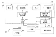
- Patent Document 1 describes a high-frequency device as shown in FIG.
- a high-frequency device 800 shown in FIG. 11 includes a plurality of noise pickup antennas (a noise pickup antenna 714 arranged around the noise source 742 and a noise pickup antenna arranged around the noise source 842). 815), the switch 824 selects a noise signal received by one of the switches 824 and inputs it to the cancel signal generation circuit 725.
- the system control unit 841 switches the switch 824 according to the situation, the high frequency device 800 can improve the reception quality.
- the present invention has been made in view of the above problems.
- a noise pickup antenna is used.
- a signal transmission / reception antenna is used to achieve a suitable communication state.
- the main purpose is to provide technology to do this.
- a wireless communication apparatus is a wireless communication apparatus that performs diversity reception and noise cancellation processing, and a signal combining unit that combines a plurality of reception signals at the time of diversity reception; In the noise canceling process, a signal synthesizing unit that synthesizes the received signal and the noise signal is shared.
- the noise cancellation unit can be effectively used, and a compact apparatus configuration can be used for noise countermeasures and a plurality of A suitable communication state can be realized in consideration of both communication using the antenna.
- (A) is a block diagram which shows schematic structure of the radio
- (b) is a schematic diagram which shows an example of a structure of the 2nd antenna for signal communication.
- 5 is a graph illustrating an example of received power of a signal in each unit when noise cancellation processing is performed in an embodiment of the present invention.
- it is a graph which shows an example of the reception power of the signal in each part at the time of performing diversity communication.
- it is a flowchart which shows the flow of the process which switches a switch based on reception quality.
- FIG. 5 is a flowchart illustrating a flow of processing for switching a switch based on a use channel in an embodiment of the present invention. It is a graph which shows an example of the noise amount for every channel in one Embodiment of this invention. In one Embodiment of this invention, it is a flowchart which shows the flow of the process which switches a switch based on the connection state of an external antenna. In one Embodiment of this invention, it is a flowchart which shows the flow of the process which switches a switch based on the amount of noise. It is a block diagram which shows schematic structure of the radio
- the wireless communication device is a portable or non-portable wireless communication device, for example, a mobile phone terminal, a portable information terminal, an in-vehicle information terminal, an in-vehicle phone terminal, a wireless communication device, an installation type
- a mobile phone terminal a portable information terminal
- an in-vehicle information terminal an in-vehicle phone terminal
- a wireless communication device an installation type
- the present invention is not limited thereto, and the present invention can be applied to a wireless communication apparatus in general.
- the content of the signal to communicate is not limited at all.
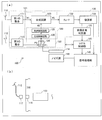
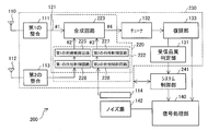
- FIG. 1A is a block diagram illustrating a schematic configuration of the wireless communication apparatus 100 according to the present embodiment.
- the wireless communication device 100 includes a first antenna (first signal receiving antenna) 110, a first matching 111, and a second antenna (second signal receiving antenna). ) 112, second matching 113, noise pickup antenna 114, first signal transmission unit 121, second signal transmission unit 122, synthesis circuit (signal synthesis unit) 123, reception quality judgment unit (reception quality judgment means, Noise amount detection means) 131, tuner 132, demodulation section 133, signal processing section 140, and system control section (switch control means) 141.
- the second antenna 112 may be an external antenna that is detachably attached to the wireless communication apparatus 100. That is, as shown in FIG. 1B, the wireless communication apparatus 100 includes a connector 116 connected to the second matching 113, and the connector 116 has an external antenna element such as an earphone antenna or an external antenna element. A connector 117 such as a cradle equipped with a connector may be connectable.
- the wireless communication device 100 includes a noise source 142.
- the noise source 142 is a part that emits a radio wave that becomes noise with respect to a received signal in accordance with the operation of the wireless communication apparatus 100, and may be a specific part or the whole of the wireless communication apparatus 100.
- the second signal transmission unit 122 includes a switch (switching unit) 124, a gain control circuit (adjustment unit) 125, and a phase control circuit (phase adjustment unit, adjustment unit) 126. Further, the first matching 111, the second matching 113, the first signal transmission unit 121, the second signal transmission unit 122, the synthesis circuit 123, the tuner 132, the demodulation unit 133, and the reception quality determination unit 131 A processing unit 130 is configured. In addition, the synthesis circuit 123, the gain control circuit 125, and the phase control circuit 126 constitute a synthesis processing unit 120.
- the gain control circuit 125 includes, for example, an amplifier and an attenuator (not shown).
- the phase control circuit 126 includes, for example, a phase shifter (not shown). The gain control circuit 125 and the phase control circuit 126 can change at least one of the amplitude and phase of the input signal within a set range.
- the first matching 111 and the second matching 113 are matching circuits that impedance-match the first antenna 110 and the second antenna 112, respectively.
- the first matching 111 and the second matching 113 may include an amplifier such as an LNA (Low Noise Amp) that amplifies a high-frequency signal.
- a signal received by the first antenna 110 is input to the first signal transmission unit 121.
- the signal received by the second antenna 112 is input to the second signal transmission unit 122.
- the noise pickup antenna 114 is disposed in the vicinity of the noise source 142. A signal (noise) received by the noise pickup antenna 114 is input to the second signal transmission unit 122.
- the first signal transmission unit 121 outputs the signal input from the first antenna 110 to the synthesis circuit 123.
- the first signal transmission unit 121 may include an amplifier such as an LNA that amplifies a high frequency signal.
- the second signal transmission unit 122 synthesizes one of the signal input from the second antenna 112 and the signal input from the noise pickup antenna 114 by adjusting at least one of amplitude and phase. Output to the circuit 123.
- the signal from the second antenna 112 is input to the port P1 of the switch 124 of the second signal transmission unit 122, and the signal from the noise pickup antenna 114 is input to the port P2.
- the switch 124 outputs a signal input to either one of the ports P1 and P2 to the phase control circuit 126.
- the phase control circuit 126 adjusts the phase of the input signal and outputs it to the gain control circuit 125.
- the gain control circuit 125 adjusts the amplitude of the input signal and outputs it to the synthesis circuit 123. Note that switching of the switch 124 and amplitude and phase adjustment amounts in the gain control circuit 125 and the phase control circuit 126 are both controlled by the system control unit 141.
- the order of the gain control circuit 125 and the phase control circuit 126 may be switched. That is, the signal output from the switch 124 is input to the gain control circuit 125, the signal output from the gain control circuit 125 is input to the phase control circuit 126, and the signal output from the phase control circuit 126 is combined. It may be inputted to the circuit 123.
- the gain control circuit 125 and the phase control circuit of the second signal transmission unit 122 (which adjusts at least one of the amplitude and phase of the input signal and outputs the adjusted signal to the synthesis circuit 123). 126) includes, for example, the following operations: the gain control circuit 125 and the phase control circuit 126 output the input signal to the synthesis circuit 123 without adjusting the amplitude and phase of the input signal.
- the gain control circuit 125 and the phase control circuit 126 output almost no signal to the synthesizing circuit 123; and the input signal is synthesized with the gain control circuit 125 and the phase control circuit 126 turned off. Output to 123 or not.
- the synthesis circuit 123 synthesizes the signal (# 1) input from the first signal transmission unit 121 and the signal (# 2) input from the second signal transmission unit 122 to form a tuner 132 as a signal (# 3). Output to.
- the signal output from the synthesis circuit 123 is tuned by the tuner 132, demodulated by the demodulation unit 133, and provided to the signal processing unit 140.
- the signal processing unit 140 performs processing such as decoding on the provided signal.
- the reception quality determination unit 131 determines reception quality such as reception power, C / N (Carrier-to-Noise ratio), noise amount, and the like for the signal demodulated by the demodulation unit 133.
- the system control unit 141 controls the switch 124, the gain control circuit 125, and the phase control circuit 126 based on the determination result of the reception quality determination unit 131 and the like. Details will be described later.
- the wireless communication device 100 When the switch 124 is tilted to the port P1, the wireless communication device 100 combines the signal from the first antenna 110 and the signal from the noise pickup antenna 114 in which at least one of the amplitude and the phase is adjusted. Noise cancellation processing.
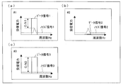
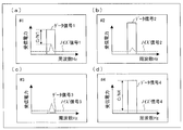
- FIG. 2 is a graph showing an example of received power of the signals (# 1 and # 2) input to the synthesis circuit 123 and the signal (# 3) output from the synthesis circuit 123 when the noise cancellation process is performed. .
- the signal (# 1) includes the noise signal 1 in addition to the data signal 1.
- the signal (# 2) has the same amplitude as that of the noise signal 1 of the signal (# 1), and the noise signal 2 has a substantially opposite phase.
- the synthesizing circuit 123 synthesizes the signal (# 1) and the signal (# 2) to cancel the noise signals, and the received power of the noise signal 3 is reduced as shown in (c) of FIG. Signal (# 3) can be output.
- the carrier-to-noise ratio C / N3 of the signal (# 3) is larger than the carrier-to-noise ratio C / N1 of the signal (# 1), and it can be seen that the reception sensitivity is improved.
- the wireless communication device 100 combines the signal from the first antenna 110 and the signal from the second antenna 112 whose amplitude and phase are adjusted, Diversity communication.
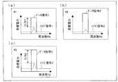
- FIG. 3 is a graph showing an example of received power of signals (# 1 and # 2) input to the combining circuit 123 and signals (# 3) output from the combining circuit 123 when performing diversity communication.
- the signal (# 1) includes a data signal 1 and a noise signal 1.
- the signal (# 2) also includes the data signal 2 and the noise signal 2.
- the combining circuit 123 outputs the signal (# 3) by combining the signal (# 1) and the signal (# 2).
- the signal (# 2) is composed of the data signal 2 and the noise signal 2, but the phase of the data signal 2 is substantially the same as that of the data signal 1, and the amplitude is appropriately adjusted.
- the synthesizing circuit 123 synthesizes the signal (# 1) and the signal (# 2), thereby adding the data signals and improving the reception power of the data signal 3 of the signal (# 3).
- the phase relationship between the data signal 1 and the noise signal 1 in the signal (# 1) and the phase relationship between the data signal 2 and the noise signal 2 in the signal (# 2) are generally Therefore, even if the data signal 1 and the data signal 2 have the same phase, the noise signal 1 and the noise signal 2 do not have the same phase. For this reason, the reception power of the noise signal 3 in the signal (# 3) does not simply improve, and as shown in FIG. 3C, the synthesis circuit 123 has a signal with a large carrier-to-noise ratio C / N3 (# 3) can be output.
- the frequency is such that no noise signal is generated, only the data signals are added, so the effect of increasing the carrier-to-noise ratio C / N3 is significant. Thereby, reception sensitivity can be improved.
- the noise signals included in the signal (# 1) and the signal (# 2) are combined so as to cancel each other as the same amplitude and opposite phase, and diversity communication is performed.
- the data signals included in the signal (# 1) and the signal (# 2) are combined in phase so that the received power is improved.
- the synthesizing processing unit 120 or the like which is the same component, performs reverse synthesizing between the noise canceling process and the diversity communication process, but it can be understood that the reception sensitivity can be improved in either case.
- Whether the wireless communication apparatus 100 performs noise cancellation processing or diversity communication may be controlled according to a criterion as described later, and processing for improving reception quality according to the situation can be performed.
- a part of a circuit for performing noise cancellation processing and diversity communication can be shared. Therefore, a plurality of signal receiving antennas and noise pickup antennas can be configured with a compact device configuration. By appropriately combining the received signals according to the situation, the communication sensitivity can be improved and a suitable communication state can be realized.
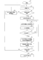
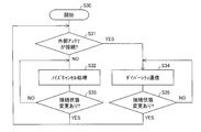
- FIG. 4 is a flowchart showing a flow of processing for switching the switch 124 based on the reception quality. The process starts in a state where the switch 124 is tilted to P0 or P1 (step S0).
- the reception processing unit 130 and the signal processing unit 140 receive a data signal (step S1). Then, the reception quality determination unit 131 determines the reception quality of the data signal received in step S1 (step S2). In the determination of reception quality, for example, C / N can be used as an index. However, the present invention is not limited to this, and other indexes such as reception power, BER (Bit Error Rate), and noise amount may be used.
- the reception quality determination unit 131 determines whether the reception quality is good (OK) or bad (NG) by comparing a specific index with, for example, a predetermined reference value.
- step S2 If it is determined in step S2 that the reception quality is good, the system control unit 141 does not switch the switch 124, and changes the amplitude adjustment amount in the gain control circuit 125 and the phase adjustment amount in the phase control circuit 126 to the current values. It keeps (step S3), returns to step S1, and continues reception.
- step S2 when it is determined in step S2 that the reception quality is poor, the system control unit 141 switches the switch 124 (step S4), and the amplitude adjustment amount and phase control in the gain control circuit 125 in steps S5 to S9.
- the phase adjustment amount in the circuit 126 is optimized.
- the system control unit 141 changes the amplitude adjustment amount in the gain control circuit 125 and the phase adjustment amount in the phase control circuit 126, thereby changing the amplitude and phase of the signal (# 2) input to the synthesis circuit 123. Change (step S5).
- the reception quality determination unit 131 measures C / N (step S6).
- the system control unit 141 repeats steps S5 and S6 until all the correspondences between the adjustment amounts of the amplitude and phase of the signal (# 2) and C / N are measured over a predetermined range (step S7). .
- the system control unit 141 determines the adjustment amount of the amplitude and phase with the best C / N as an optimum value (step S8), and the gain is set so that the adjustment amount of the amplitude and phase becomes the optimum value.
- the control circuit 125 and the phase control circuit 126 are controlled (step S9).
- reception quality is determined based on C / N.
- other indicators may be used to determine the reception quality.
- step S7 it is not necessary to measure all the correspondences between the adjustment amount and C / N. For example, when an adjustment amount exceeding a predetermined C / N reference value is found, step 7 is ended there. In step S8, the adjustment amount may be determined as the optimum value.
- the system control unit 141 calculates the optimum value of the adjustment amount so as to increase the C / N of the signal (# 3) according to another known optimization algorithm,
- the gain control circuit 125 and the phase control circuit 126 may be controlled according to the calculated optimum value.
- the reception quality determination unit 131 determines the reception quality again (step S10). If it is determined in step S10 that the reception quality is good, the process returns to step S1 to continue reception. If it is determined in step S10 that the reception quality is poor, the system control unit 141 switches the switch 124 (step S11), and again in steps S5 to S9, the amplitude adjustment amount in the gain control circuit 125 and The phase adjustment amount in the phase control circuit 126 is optimized.
- step S10 when it is determined that the reception quality is poor multiple times and steps S5 to S11 are repeated, the switching process of the switch 124 based on the reception quality may be stopped at a predetermined timing.
- the wireless communication device 100 performs the processing as described above, it is possible to perform processing with good reception quality among noise cancellation processing and diversity communication. Therefore, it is possible to realize a suitable communication state according to the situation. .
- FIG. 5 is a flowchart showing a flow of processing for switching a switch based on a used channel. The process is started with the use channel selected (step S20).
- the amount of noise when reception is performed using the channel is measured in advance.
- An example of the measurement result is shown in FIG. In the example shown in FIG. 6, when the channel is “X” (X1 or X2), the amount of noise is large.
- description will be made under this condition.
- the system control unit 141 determines whether or not the channel (frequency band) used in the reception processing unit 130 is a specific channel (“X”) in which the amount of noise increases (step S21).
- step S21 When it is determined in step S21 that the used channel is “X”, the system control unit 141 causes the reception processing unit 130 to perform noise cancellation processing (step S22). That is, the switch 124 is brought down to the port P1. At this time, the system control unit 141 may optimize the amplitude adjustment amount in the gain control circuit 125 and the phase adjustment amount in the phase control circuit 126 as in steps S5 to S9. In addition, the optimum values of the amplitude and phase adjustment amounts for noise when using the channel “X” are measured in advance and stored in the system control unit 141, and the system control unit 141 stores the optimum values stored in advance. It is possible to read out and optimize the amplitude adjustment amount in the gain control circuit 125 and the phase adjustment amount in the phase control circuit 126.
- Step S22 is repeated until the used channel is changed or the communication is completed (Step S23). If the channel used is changed, the process returns to step S21.
- step S21 when it is determined in step S21 that the used channel is other than “X”, it is known in advance that the amount of noise is not large, and thus the system control unit 141 executes diversity communication to the reception processing unit 130. (Step S24). That is, the switch 124 is brought down to the port P2. At this time, the system control unit 141 may optimize the amplitude adjustment amount in the gain control circuit 125 and the phase adjustment amount in the phase control circuit 126 as in steps S5 to S9. Then, step S24 is repeated until the used channel is changed or communication is completed (step S25). If the channel used is changed, the process returns to step S21.
- the amount of noise is reduced by performing a noise cancellation process, thereby suitably improving communication sensitivity.
- the communication sensitivity can be improved by performing diversity communication, so that a suitable communication state according to the situation can be realized.
- FIG. 7 is a flowchart showing a flow of processing for switching the switch based on the connection state of the external antenna. The process is started in a state where the system control unit 141 can detect the connection state of the external antenna (step S30).
- the second antenna 112 is an external antenna connected to the connector 116 of the wireless communication apparatus 100, and the system control unit 141 determines whether or not the second antenna 112 is connected to the connector 116. The case where it can be detected will be described below.
- the system control unit 141 detects the connection state of the second antenna 112 by, for example, measuring a reflected power from a physical mechanism (not shown) or the connector 116.
- the system control unit 141 determines whether or not the second antenna 112 is connected (step S31).
- step S31 When it is determined in step S31 that the second antenna 112 is not connected, the system control unit 141 causes the reception processing unit 130 to perform noise cancellation processing (step S32). That is, the switch 124 is brought down to the port P1. At this time, the system control unit 141 may optimize the amplitude adjustment amount in the gain control circuit 125 and the phase adjustment amount in the phase control circuit 126 as in steps S5 to S9. And step S32 is repeated until the change of the connection state of the 2nd antenna 112 is detected or communication is complete
- step S31 when it is determined in step S31 that the second antenna 112 is connected, the system control unit 141 causes the reception processing unit 130 to execute diversity communication (step S34). That is, the switch 124 is brought down to the port P2. At this time, the system control unit 141 may optimize the amplitude adjustment amount in the gain control circuit 125 and the phase adjustment amount in the phase control circuit 126 as in steps S5 to S9. Then, step S34 is repeated until the used channel is changed or communication is completed (step S35). If a change in the connection state of the second antenna 112 is detected, the process returns to step S31.
- the second antenna 112 is connected and diversity communication is enabled.
- the built-in noise is transmitted. Since noise cancellation processing is performed using the pickup antenna 114, a suitable communication state according to the situation can be realized.
- FIG. 8 is a flowchart showing a flow of processing for switching the switch based on the amount of noise. The processing is started in a state where the reception quality determination unit 131 can detect the amount of noise (step S40).
- the method of detecting the amount of noise by the reception quality determination unit 131 may be configured to detect the magnitude of the amount of noise based on the power of the noise signal received by the noise pickup antenna 114, for example. May be detected.
- the reception quality determination unit 131 compares the detected noise amount with a predetermined reference value (step S41).
- step S41 When it is determined in step S41 that the amount of noise exceeds the reference value, the system control unit 141 causes the reception processing unit 130 to perform noise cancellation processing (step S42). That is, the switch 124 is brought down to the port P1. At this time, the system control unit 141 may optimize the amplitude adjustment amount in the gain control circuit 125 and the phase adjustment amount in the phase control circuit 126 as in steps S5 to S9. Then, at an appropriately set timing, the process returns to step S41 to make a determination again.
- step S41 when it is determined in step S41 that the amount of noise is equal to or less than the reference value, the system control unit 141 causes the reception processing unit 130 to execute diversity communication (step S43). That is, the switch 124 is brought down to the port P2. At this time, the system control unit 141 may optimize the amplitude adjustment amount in the gain control circuit 125 and the phase adjustment amount in the phase control circuit 126 as in steps S5 to S9. Then, at an appropriately set timing, the process returns to step S41 to make a determination again.
- the wireless communication device 100 Since the wireless communication device 100 performs the above processing, noise cancellation processing is performed when the amount of noise is large, and diversity communication is performed when the amount of noise is small, so that a suitable communication state according to the situation can be realized. it can.
- the system control unit 100 can realize a suitable communication state according to the situation by controlling the switch 124, the gain control circuit 125, and the phase control circuit 126 based on various indexes.
- the system control unit 100 may perform control based on a plurality of indices.
- the system control unit 100 may perform two or more processes among the processes illustrated in FIGS.
- the switch 124 has ports corresponding to the total number of the second antennas and the noise pickup antennas, and any one of the signals input to all the ports is used as the gain control circuit 125 and the phase control circuit 126. May be output to the synthesis circuit 123 via
- the second signal transmission unit 122 may include a plurality of switches, gain control circuits, and phase control circuits. That is, the ports corresponding to the total number of the second antennas and the noise pickup antennas may be divided into a plurality of switches, and signals may be selected in each switch. At this time, the signal selected in each switch is adjusted in at least one of amplitude and phase by a gain control circuit and a phase control circuit connected to each switch, and is input to the synthesis circuit 123 and synthesized.
- FIG. 9 is a block diagram showing a schematic configuration of a wireless communication apparatus 200 according to another embodiment (second embodiment) of the present invention.
- the same members as those in the wireless communication device 100 are denoted by the same reference numerals and description thereof is omitted.
- the wireless communication device 200 differs from the wireless communication device 100 in the configuration of the reception processing unit 230 and the operation of the system control unit 241. More specifically, in the reception processing unit 230, the second signal transmission unit 222 converts both the signal input from the second antenna 112 and the signal input from the noise pickup antenna 114 into at least an amplitude and a phase. Any one of them is adjusted and output to the synthesis circuit (signal synthesis unit) 223, and the synthesis circuit 223 receives the signal (# 1) input from the first signal transmission unit 121 and the second signal transmission unit 222. Are combined with each other (# 2 and # 3) and output to the tuner 132 as a signal (# 4).
- the second signal transmission unit 222 receives the signals from the first phase control circuit (phase adjustment unit, adjustment unit) 226 and the first phase control circuit 226 to which the signal from the second antenna 112 is input.
- a second gain control circuit (adjustment unit) 227 to which a signal from the circuit 228 is input is provided.
- the signal (# 2) is output from the first gain control circuit 225 to the combining circuit 223, and the signal (# 3) is output from the second gain control circuit 227 to the combining circuit 223.
- signals from the second antenna 112 and the noise pickup antenna 114 are input to the synthesis processing unit 220.
- the order of the first gain control circuit 225 and the first phase control circuit 226 and the order of the second gain control circuit 227 and the first phase control circuit 228 may be interchanged.
- the wireless communication apparatus 200 includes a signal from the first antenna 110, a signal from the second antenna 112 in which at least one of amplitude and phase is adjusted, and a noise pickup in which at least one of amplitude and phase is adjusted.
- the signal from the antenna 114 is combined to perform diversity communication and noise cancellation processing.
- FIG. 10 shows an example of the received power of the signals (# 1, # 2, and # 3) input to the synthesis circuit 223 and the signal (# 4) output from the synthesis circuit 123 when performing the noise cancellation process. It is a graph.
- the signal (# 1) includes a data signal 1 and a noise signal 1. Further, as shown in FIG. 10B, the data signal 2 and the noise signal 2 are also included in the signal (# 2). Further, as shown in FIG. 10C, the signal (# 3) contains almost only a noise signal.
- the synthesizing circuit 223 synthesizes the signal (# 1), the signal (# 2), and the signal (# 3) to output the signal (# 4).
- the amplitude and phase of the signal (# 2) are adjusted so that the carrier-to-noise ratio C / N4 of the signal (# 4) is larger than the carrier-to-noise ratio C / N1 of the signal (# 1).
- FIG. 10A the signal (# 1) includes a data signal 1 and a noise signal 1.
- the data signal 2 and the noise signal 2 are also included in the signal (# 2).
- the signal (# 3) contains almost only a noise signal.
- the synthesizing circuit 223 synthesizes the signal (# 1),
- the synthesis circuit 223 can output a signal (# 4) having a large carrier-to-noise ratio C / N4. Further, the amplitude and phase of the signal (# 3) are canceled by the noise signal in the signal (# 4), and the carrier-to-noise ratio C / N4 becomes larger than the carrier-to-noise ratio C / N1 of the signal (# 1). By adjusting in this way, as shown in FIG. 10D, the synthesis circuit 223 can output a large signal (# 4) with a reduced noise signal. Thereby, reception sensitivity can be improved.
- the system control unit 241 controls the amplitude or phase adjustment amount in the first gain control circuit 225, the first phase control circuit 226, the second gain control circuit 227, and the second phase control circuit 228. As described above, the reception sensitivity of the wireless communication apparatus 200 can be improved. For example, the system control unit 241 performs the first gain control circuit 225, the first phase control circuit 226, the second gain control circuit 227, and the second phase control circuit 228 in accordance with steps S5 to S9 shown in FIG. May be controlled, or other known optimization algorithms may be used to calculate the optimum value of the adjustment amount so as to increase the C / N of the signal (# 4), and each amplitude according to the calculated optimum value. In addition, the first gain control circuit 225, the first phase control circuit 226, the second gain control circuit 227, and the second phase control circuit 228 may be controlled so as to adjust the phase.
- the wireless communication apparatus 200 can share a part of a circuit for performing noise cancellation processing and diversity communication. Therefore, a plurality of signal receiving antennas and The signal received by the noise pickup antenna can be appropriately combined to improve the reception sensitivity suitably.
- the second signal transmission unit 122 includes a further gain control circuit and a phase control circuit, and signals from all the second antennas and noise pickup antennas are different from each other. May be input to the synthesis circuit 223.
- the second signal transmission unit may include a switch, select a signal to be output to the synthesis circuit by switching the switch, and output a plurality of signals to the synthesis circuit.
- a switch may be connected to the second phase control circuit 228, and signals from a plurality of noise pickup antennas may be input to the switch.
- the reception sensitivity can be further improved by appropriately selecting signals from a plurality of noise pickup antennas based on a predetermined reference and inputting them to the synthesis circuit 223.
- the signal input to the switch is not limited to signals from a plurality of noise pickup antennas, but may be signals from a plurality of signal receiving antennas. Signals from both the noise pickup antenna and the signal receiving antenna It may be.
- the second signal transmission unit receives the signal received by the one or more second signal receiving antennas and the signal received by the one or more noise pickup antennas. As long as at least one of the signals is adjusted to at least one of the phase and the amplitude, the signal may be output to the synthesis circuit. If the second signal transmission unit has the above-described configuration, a part of the circuit for performing noise cancellation processing and diversity communication can be shared, so that a plurality of signals can be received with a compact device configuration. The signals received by the antenna for noise and the antenna for noise pickup can be appropriately combined to perform suitable communication.
- the wireless communication devices 100 and 200 perform diversity communication using a plurality of signal receiving antennas (the first antenna 110 and the second antenna 112).
- the present invention is not limited to this, and radio communication apparatuses 100 and 200 may use a plurality of signal receiving antennas as adaptive array antennas, or to realize a technology using other plurality of antennas. You may use for.
- system control units 141 and 241 may be realized in hardware by a logic circuit formed on an integrated circuit (IC chip), or may be realized in software using a CPU (Central Processing Unit). May be.
- the system control units 141 and 241 include a CPU that executes instructions of a program that implements each function, a ROM (Read Memory) that stores the program, a RAM (Random Access Memory) that expands the program, and the above
- a storage device such as a memory for storing programs and various data is provided.
- An object of the present invention is a recording in which program codes (execution format program, intermediate code program, source program) of control programs of the system control units 141 and 241 which are software for realizing the functions described above are recorded so as to be readable by a computer. This can also be achieved by supplying the medium to the system control units 141 and 241 and reading and executing the program code recorded on the recording medium by the computer (or CPU or MPU).
- Examples of the recording medium include tapes such as magnetic tapes and cassette tapes, magnetic disks such as floppy (registered trademark) disks / hard disks, and disks including optical disks such as CD-ROM / MO / MD / DVD / CD-R.
- IC cards including memory cards
- semiconductor memories such as mask ROM / EPROM / EEPROM / flash ROM, or PLD (Programmable logic device) or FPGA (Field Programmable Gate Array) Logic circuits can be used.
- system control units 141 and 241 may be configured to be connectable to a communication network, and the program code may be supplied via the communication network.
- the communication network is not particularly limited as long as it can transmit the program code.
- the Internet intranet, extranet, LAN, ISDN, VAN, CATV communication network, virtual private network (Virtual Private Network), telephone line network, mobile communication network, satellite communication network, etc. can be used.
- the transmission medium constituting the communication network may be any medium that can transmit the program code, and is not limited to a specific configuration or type.
- wired lines such as IEEE 1394, USB, power line carrier, cable TV line, telephone line, ADSL (Asymmetric Digital Subscriber Line) line, infrared rays such as IrDA and remote control, Bluetooth (registered trademark), IEEE 802.11 wireless, HDR ( It can also be used by wireless such as High Data Rate, NFC (Near Field Communication), DLNA (Digital Living Network Alliance), mobile phone network, satellite line, and terrestrial digital network.
- wired lines such as IEEE 1394, USB, power line carrier, cable TV line, telephone line, ADSL (Asymmetric Digital Subscriber Line) line, infrared rays such as IrDA and remote control, Bluetooth (registered trademark), IEEE 802.11 wireless, HDR ( It can also be used by wireless such as High Data Rate, NFC (Near Field Communication), DLNA (Digital Living Network Alliance), mobile phone network, satellite line, and terrestrial digital network.
- wired lines such as IEEE 1394, USB, power line carrier, cable TV line, telephone line, ADSL (Asymmetric Digital Subscriber Line) line,
- the wireless communication apparatus is a wireless communication apparatus that performs diversity reception and noise cancellation processing, and includes a signal combining unit that combines a plurality of received signals at the time of diversity reception, and the noise.
- a signal synthesis unit that synthesizes the reception signal and the noise signal is shared.
- the wireless communication device includes a phase adjustment unit that adjusts the phase of a part of the plurality of reception signals during the diversity reception, and the noise signal during the noise cancellation processing. It is preferable to share a phase adjustment unit that adjusts the phase of the phase.
- phase adjustment unit used for noise cancellation processing can be used for diversity reception even when no noise is generated, noise is generated. When not in use, unnecessary parts can be further reduced. Thereby, a suitable communication state is realizable with a more compact apparatus structure.
- the phase adjustment unit may receive the phase of the part of the reception signal and the reception signal to be combined with the part of the reception signal in the signal combining unit during the diversity reception. So that the phase of the noise signal is opposite to the phase of the received signal to be combined with the noise signal in the signal combiner during the noise canceling process. It is preferable to adjust to.
- the wireless communication apparatus includes a switching unit that switches a signal input to the phase adjustment unit, and the switching unit switches the partial reception signal to be input to the phase adjustment unit.
- the phase adjusting unit adjusts the phase of the signal input to the phase adjusting unit so that the signal synthesizing unit has the same phase as the phase of the received signal to be combined with the partial received signal.
- the phase adjustment unit converts the phase of the signal input to the phase adjustment unit in the signal synthesis unit. It is preferable to adjust so that the phase of the received signal to be combined with the noise signal is opposite to that of the received signal.
- the phase adjustment unit adjusts the phase according to the type of the input signal after switching in accordance with the switching of the signal input to the phase adjustment unit. Can be suitably performed, and diversity reception and noise cancellation processing can be suitably performed.
- a wireless communication apparatus includes a first signal transmission antenna that outputs a reception signal received by a first signal reception antenna, a noise pickup antenna, and a first signal reception antenna to the signal synthesis unit. And a reception signal received by a second signal reception antenna different from the first signal reception antenna, and a noise signal received by the noise pickup antenna, and the received reception signal and noise signal
- a second signal transmission unit that adjusts at least one of the phase and amplitude of the signal and outputs the signal to the signal synthesis unit, and the second signal receiving antenna receives the second signal transmission unit. Diversity combining is performed using at least the received signal, and noise cancellation processing is performed using at least the noise signal received by the noise pickup antenna. Or may be carried out.
- the signal synthesis unit adjusts the amplitude and phase of the signal received by the other signal receiving antenna and the noise pickup antenna with respect to the signal received by the first signal receiving antenna. Since they can be combined as appropriate, they function as part of a circuit for performing noise cancellation processing and part of a circuit for performing communication using a plurality of antennas. As described above, according to the above configuration, it is possible to share a part of a circuit for performing noise canceling processing and communication using a plurality of antennas. A suitable communication state can be realized in consideration of both of the utilized communications.
- the second signal receiving antenna may be a removable external antenna.
- the second signal receiving antenna is a removable external antenna such as an earphone antenna. Therefore, it is possible to avoid the influence of the radio communication device as a ground and to obtain better antenna characteristics than the first signal receiving antenna that is often arranged in the radio communication device. Further, since the distance from the noise source of the wireless communication device can be taken, the amount of noise received by the second signal receiving antenna should be smaller than the amount of noise received by the first signal receiving antenna. Is possible. As described above, according to the above configuration, it is possible to improve the antenna characteristics of the second signal receiving antenna and realize more suitable diversity communication.
- the radio communication apparatus preferably includes a tuner that tunes at least a reception signal received by the first signal receiving antenna, and a signal synthesized by the signal synthesis unit is preferably input to the tuner.
- a tuner can be shared in a circuit for performing noise cancellation processing and a circuit for performing communication using a plurality of antennas. Thereby, a suitable communication state is realizable with a compact apparatus structure.
- the second signal transmission unit includes a switch, and by switching the switch, the signal output to the signal synthesis unit is received and the received signal input to the second signal transmission unit and It is preferable to select from noise signals.
- the signal synthesizer only needs to synthesize the signal input from the first signal transmission unit and the signal selected by the switch. A state can be realized.
- the second signal transmission unit includes an adjustment unit that adjusts at least one of a phase and an amplitude of a signal output to the signal synthesis unit, and the switch includes the adjustment unit, It is preferable to connect either the second signal receiving antenna or the noise pickup antenna.
- the adjustment unit can be shared in a circuit for performing noise cancellation processing and a circuit for performing communication using a plurality of antennas, which is preferable with a more compact device configuration.
- a communication state can be realized.
- the wireless communication apparatus preferably includes switch control means for switching the switch.
- the wireless communication device may include reception quality determination means for determining reception quality, and the switch control means may switch the switch according to a determination result of the reception quality determination means.
- the switch control means may switch the switch according to a frequency band in which the wireless communication device is performing wireless communication.
- the noise amount is reduced by performing noise cancellation processing, thereby suitably improving communication sensitivity.
- communication sensitivity can be improved by performing communication using a plurality of antennas, a suitable communication state corresponding to the situation can be realized.
- the second signal receiving antenna is an external antenna
- the switch control means is configured to output the second signal when the second signal receiving antenna is connected to the wireless communication device.
- the switch may be switched so that a reception signal received by the reception antenna is input to the signal synthesis unit.
- the wireless communication device includes noise amount detection means for detecting the amount of noise in the wireless communication device, and the switch control means is configured to detect when the noise amount detected by the noise amount detection means exceeds a reference value.
- the switch control means is configured to detect when the noise amount detected by the noise amount detection means exceeds a reference value.
- the noise signal received by the noise pickup antenna is input to the signal synthesizer, and the magnitude of the noise is below a reference value, the received signal received by the second signal receiving antenna is the signal synthesizer.
- the switch may be switched so as to be input to.
- the wireless communication apparatus there may be two or more noise pickup antennas or two or more second signal receiving antennas.
- a program for operating the apparatus according to the present invention which causes a computer to realize the functions of each of the above apparatuses, and a computer-readable recording medium recording the program are also included in the scope of the present invention.
- the present invention can be used in the field of manufacturing wireless communication devices.
- Wireless communication device 110 First antenna (first signal receiving antenna) 111 First matching 112 Second antenna (second signal receiving antenna) 113 Second Matching 114 Noise Pickup Antenna 120, 220 Combining and etc. Processing Unit 121 First Signal Transmission Unit 122, 222 Second Signal Transmission Unit 123, 223 Synthesis Circuit (Signal Synthesis Unit) 124 switch (switching part) 125 Gain control circuit (adjustment unit) 126 Phase control circuit (phase adjustment unit, adjustment unit) 225 First gain control circuit (adjustment unit) 226 First phase control circuit (phase adjustment unit, adjustment unit) 227 Second gain control circuit (adjustment unit) 228 Second phase control circuit (phase adjustment unit, adjustment unit) 130, 230 Reception processing unit 131 Reception quality determination unit (reception quality determination means, noise amount detection means) 132 Tuner 133 Demodulator 140 Signal Processor 141, 241 System Controller (Switch Control Unit) 142 Noise source
Abstract
Description
以下、図面を参照して、本発明の一実施形態(第1実施形態)に係る無線通信装置を説明する。なお、本実施形態に係る無線通信装置は、携帯型または非携帯型の無線通信装置であり、例えば、携帯電話端末、携帯情報端末、車載情報端末、車載電話端末、無線通信機器、設置型の情報端末等であり得るが、これらに限定されず、本発明は無線通信装置一般に適用することができる。また、通信する信号の内容も全く限定されない。
図1の(a)は、本実施形態に係る無線通信装置100の概略構成を示すブロック図である。図1の(a)に示すように、無線通信装置100は、第1のアンテナ(第1の信号受信用アンテナ)110、第1の整合111、第2のアンテナ(第2の信号受信用アンテナ)112、第2の整合113、ノイズピックアップ用アンテナ114、第1の信号伝送部121、第2の信号伝送部122、合成回路(信号合成部)123、受信品質判定部(受信品質判定手段、ノイズ量検出手段)131、チューナ132、復調部133、信号処理部140、およびシステム制御部(スイッチ制御手段)141を備えている。
無線通信装置100は、スイッチ124がポートP1に倒れている場合、第1のアンテナ110からの信号と、振幅および位相の少なくとも何れかが調整されたノイズピックアップ用アンテナ114からの信号とを合成して、ノイズキャンセル処理を行う。
続いて、システム制御部141によるスイッチ124、利得制御回路125および位相制御回路126の制御について説明する。以下、システム制御部141による制御のいくつかのバリエーションを説明するが、本発明はこれらに限定されない。
上記では、第2のアンテナおよびノイズピックアップ用アンテナがそれぞれ1つである構成について説明したが、本実施形態はこれに限定されず、第2のアンテナおよびノイズピックアップ用アンテナはそれぞれ複数であってもよい。
図9は、本発明の他の実施形態(第2実施形態)に係る無線通信装置200の概略構成を示すブロック図である。無線通信装置200において、無線通信装置100と同様の部材については、同じ番号を付し、説明を省略する。
本実施形態においても、第2のアンテナおよびノイズピックアップ用アンテナはそれぞれ複数であってもよい。この場合、例えば、第2の信号伝送部122が、さらなる利得制御回路および位相制御回路を備え、全ての第2のアンテナおよびノイズピックアップ用アンテナからの信号が、それぞれ異なる利得制御回路および位相制御回路を介して合成回路223に入力されるようになっていてもよい。
最後に、システム制御部141および241は、集積回路(ICチップ)上に形成された論理回路によってハードウェア的に実現してもよいし、CPU(Central Processing Unit)を用いてソフトウェア的に実現してもよい。
以上のように、本発明に係る無線通信装置は、ダイバーシティ受信およびノイズキャンセル処理を行う無線通信装置であって、該ダイバーシティ受信の際に、複数の受信信号を合成する信号合成部と、該ノイズキャンセル処理の際に、受信信号およびノイズ信号を合成する信号合成部と、を共用していることを特徴としている。
110 第1のアンテナ(第1の信号受信用アンテナ)
111 第1の整合
112 第2のアンテナ(第2の信号受信用アンテナ)
113 第2の整合
114 ノイズピックアップ用アンテナ
120、220 合成等処理部
121 第1の信号伝送部
122、222 第2の信号伝送部
123、223 合成回路(信号合成部)
124 スイッチ(切り換え部)
125 利得制御回路(調整部)
126 位相制御回路(位相調整部、調整部)
225 第1の利得制御回路(調整部)
226 第1の位相制御回路(位相調整部、調整部)
227 第2の利得制御回路(調整部)
228 第2の位相制御回路(位相調整部、調整部)
130、230 受信処理部
131 受信品質判定部(受信品質判定手段、ノイズ量検出手段)
132 チューナ
133 復調部
140 信号処理部
141、241 システム制御部(スイッチ制御手段)
142 ノイズ源
Claims (15)
- ダイバーシティ受信およびノイズキャンセル処理を行う無線通信装置であって、
該ダイバーシティ受信の際に、複数の受信信号を合成する信号合成部と、
該ノイズキャンセル処理の際に、受信信号およびノイズ信号を合成する信号合成部と、
を共用していることを特徴とする無線通信装置。 - 上記ダイバーシティ受信の際に、上記複数の受信信号のうちの一部の受信信号の位相を調整する位相調整部と、
上記ノイズキャンセル処理の際に、上記ノイズ信号の位相を調整する位相調整部と、
を共用していることを特徴とする請求項1に記載の無線通信装置。 - 上記位相調整部は、
上記ダイバーシティ受信の際に、上記一部の受信信号の位相を、上記信号合成部において当該一部の受信信号と合成されるべき受信信号の位相と同位相になるように調整し、
上記ノイズキャンセル処理の際に、上記ノイズ信号の位相を、上記信号合成部において当該ノイズ信号と合成されるべき受信信号の位相と逆位相になるように調整する
ことを特徴とする請求項2に記載の無線通信装置。 - 上記位相調整部に入力される信号を切り換える切り換え部を備え、
上記切り換え部が、上記位相調整部に上記一部の受信信号が入力されるように切り換えたとき、上記位相調整部は、当該上記位相調整部に入力された信号の位相を、上記信号合成部において当該一部の受信信号と合成されるべき受信信号の位相と同位相になるように調整し、
上記切り換え部が、上記位相調整部に上記ノイズ信号が入力されるように切り換えたとき、上記位相調整部は、当該上記位相調整部に入力された信号の位相を、上記信号合成部において当該ノイズ信号と合成されるべき受信信号の位相と逆位相になるように調整する
ことを特徴とする請求項2または3に記載の無線通信装置。 - 第1の信号受信用アンテナと、
ノイズピックアップ用アンテナと、
第1の信号受信用アンテナが受信した受信信号を上記信号合成部に出力する第1の信号伝送部と、
第1の信号受信用アンテナとは異なる第2の信号受信用アンテナが受信した受信信号、および、該ノイズピックアップ用アンテナが受信したノイズ信号が入力され、入力された受信信号およびノイズ信号のうちの少なくとも1つの信号を、位相および振幅の少なくとも何れかを調整して、上記信号合成部に出力する第2の信号伝送部と、
を備えており、
第2の信号受信用アンテナが受信した受信信号を少なくとも用いてダイバーシティ合成を行い、
該ノイズピックアップ用アンテナが受信したノイズ信号を少なくとも用いてノイズキャンセル処理を行う
ことを特徴とする請求項1~4の何れか1項に記載の無線通信装置。 - 第2の信号受信用アンテナが、着脱可能な外部アンテナであることを特徴とする請求項5に記載の無線通信装置。
- 少なくとも第1の信号受信用アンテナが受信した受信信号をチューニングするチューナを備え、
該チューナには、上記信号合成部が合成した信号が入力されることを特徴とする請求項5または6に記載の無線通信装置。 - 第2の信号伝送部は、スイッチを備え、該スイッチの切り替えにより、上記信号合成部に出力する信号を、第2の信号伝送部に入力された受信信号およびノイズ信号から選択することを特徴とする請求項5~7の何れか1項に記載の無線通信装置。
- 第2の信号伝送部は、上記信号合成部に出力する信号の位相および振幅の少なくとも何れかを調整する調整部を備え、上記スイッチは、該調整部と、第2の信号受信用アンテナおよび上記ノイズピックアップ用アンテナのうちの何れか一方とを接続することを特徴とする請求項8に記載の無線通信装置。
- 上記スイッチを切り替えるスイッチ制御手段を備えていることを特徴とする請求項8または9に記載の無線通信装置。
- 受信品質を判定する受信品質判定手段を備え、
上記スイッチ制御手段は、該受信品質判定手段の判断結果に応じて、上記スイッチを切り替えることを特徴とする請求項10に記載の無線通信装置。 - 上記スイッチ制御手段は、上記無線通信装置が無線通信を行っている周波数帯に応じて、上記スイッチを切り替えることを特徴とする請求項10または11に記載の無線通信装置。
- 第2の信号受信用アンテナは、外部アンテナであり、
上記スイッチ制御手段は、第2の信号受信用アンテナが上記無線通信装置に接続されたときに、第2の信号受信用アンテナが受信した受信信号が上記信号合成部に入力されるように、上記スイッチを切り替えることを特徴とする請求項10~12の何れか1項に記載の無線通信装置。 - 上記無線通信装置におけるノイズの大きさを検出するノイズ量検出手段を備え、
上記スイッチ制御手段は、該ノイズ量検出手段が検出したノイズの大きさが基準値を超えるときは、上記ノイズピックアップ用アンテナが受信したノイズ信号が上記信号合成部に入力され、該ノイズの大きさが基準値以下のときは、第2の信号受信用アンテナが受信した受信信号が上記信号合成部に入力されるように、上記スイッチを切り替えることを特徴とする請求項10~13の何れか1項に記載の無線通信装置。 - 上記ノイズピックアップ用アンテナが2本以上であるか、または、第2の信号受信用アンテナが2本以上であることを特徴とする請求項5~14の何れか1項に記載の無線通信装置。
Priority Applications (3)
| Application Number | Priority Date | Filing Date | Title |
|---|---|---|---|
| US13/876,575 US8818306B2 (en) | 2010-12-22 | 2011-12-19 | Wireless communication device |
| CN201180052019.5A CN103168433B (zh) | 2010-12-22 | 2011-12-19 | 无线通信装置 |
| JP2012549785A JP5464628B2 (ja) | 2010-12-22 | 2011-12-19 | 無線通信装置 |
Applications Claiming Priority (2)
| Application Number | Priority Date | Filing Date | Title |
|---|---|---|---|
| JP2010286380 | 2010-12-22 | ||
| JP2010-286380 | 2010-12-22 |
Publications (1)
| Publication Number | Publication Date |
|---|---|
| WO2012086566A1 true WO2012086566A1 (ja) | 2012-06-28 |
Family
ID=46313836
Family Applications (1)
| Application Number | Title | Priority Date | Filing Date |
|---|---|---|---|
| PCT/JP2011/079292 WO2012086566A1 (ja) | 2010-12-22 | 2011-12-19 | 無線通信装置 |
Country Status (4)
| Country | Link |
|---|---|
| US (1) | US8818306B2 (ja) |
| JP (1) | JP5464628B2 (ja) |
| CN (1) | CN103168433B (ja) |
| WO (1) | WO2012086566A1 (ja) |
Families Citing this family (4)
| Publication number | Priority date | Publication date | Assignee | Title |
|---|---|---|---|---|
| US9722713B2 (en) * | 2015-06-26 | 2017-08-01 | Intel IP Corporation | Architecture and control of analog self-interference cancellation |
| JP7033887B2 (ja) * | 2017-11-08 | 2022-03-11 | キヤノン株式会社 | 通信装置およびその制御方法、プログラム |
| US20190190555A1 (en) * | 2017-12-18 | 2019-06-20 | Government of the United States, as epresented by the Secretary of the Air Force | Very low frequency noise cancellation receiver system |
| JPWO2020203875A1 (ja) * | 2019-03-29 | 2020-10-08 |
Citations (5)
| Publication number | Priority date | Publication date | Assignee | Title |
|---|---|---|---|---|
| JP2003018074A (ja) * | 2001-06-29 | 2003-01-17 | Toshiba Corp | 無線基地局及びビーム制御方法 |
| JP2005252533A (ja) * | 2004-03-03 | 2005-09-15 | Toyota Central Res & Dev Lab Inc | 通信制御装置 |
| WO2009128221A1 (ja) * | 2008-04-16 | 2009-10-22 | パナソニック株式会社 | アンテナ結合相関除去方法およびアンテナ結合相関除去機能を備えた無線装置 |
| WO2009136494A1 (ja) * | 2008-05-09 | 2009-11-12 | パナソニック株式会社 | 復調装置 |
| JP2010118880A (ja) * | 2008-11-13 | 2010-05-27 | Panasonic Corp | 受信装置 |
Family Cites Families (4)
| Publication number | Priority date | Publication date | Assignee | Title |
|---|---|---|---|---|
| US2860238A (en) * | 1953-03-05 | 1958-11-11 | Motorola Inc | Diversity receiving system |
| US6128355A (en) * | 1997-05-21 | 2000-10-03 | Telefonaktiebolget Lm Ericsson | Selective diversity combining |
| US20100007742A1 (en) | 2008-07-09 | 2010-01-14 | Panasonic Corporation | High frequency receiver and high frequency device using the same |
| JP2010021682A (ja) | 2008-07-09 | 2010-01-28 | Panasonic Corp | 高周波受信部とこれを用いた高周波機器 |
-
2011
- 2011-12-19 CN CN201180052019.5A patent/CN103168433B/zh not_active Expired - Fee Related
- 2011-12-19 WO PCT/JP2011/079292 patent/WO2012086566A1/ja active Application Filing
- 2011-12-19 JP JP2012549785A patent/JP5464628B2/ja not_active Expired - Fee Related
- 2011-12-19 US US13/876,575 patent/US8818306B2/en not_active Expired - Fee Related
Patent Citations (5)
| Publication number | Priority date | Publication date | Assignee | Title |
|---|---|---|---|---|
| JP2003018074A (ja) * | 2001-06-29 | 2003-01-17 | Toshiba Corp | 無線基地局及びビーム制御方法 |
| JP2005252533A (ja) * | 2004-03-03 | 2005-09-15 | Toyota Central Res & Dev Lab Inc | 通信制御装置 |
| WO2009128221A1 (ja) * | 2008-04-16 | 2009-10-22 | パナソニック株式会社 | アンテナ結合相関除去方法およびアンテナ結合相関除去機能を備えた無線装置 |
| WO2009136494A1 (ja) * | 2008-05-09 | 2009-11-12 | パナソニック株式会社 | 復調装置 |
| JP2010118880A (ja) * | 2008-11-13 | 2010-05-27 | Panasonic Corp | 受信装置 |
Also Published As
| Publication number | Publication date |
|---|---|
| CN103168433A (zh) | 2013-06-19 |
| CN103168433B (zh) | 2015-11-25 |
| US20130210377A1 (en) | 2013-08-15 |
| JPWO2012086566A1 (ja) | 2014-05-22 |
| US8818306B2 (en) | 2014-08-26 |
| JP5464628B2 (ja) | 2014-04-09 |
Similar Documents
| Publication | Publication Date | Title |
|---|---|---|
| US7529528B2 (en) | Power consumption controlling apparatus for high frequency amplifier | |
| WO2015101343A1 (en) | Wireless electronic device with switchable antenna system cross-reference to related application (s) and claim of priority | |
| US8103235B2 (en) | Communicating apparatus, noise canceling method and memory product | |
| US8843097B2 (en) | Method and system for blocker attenuation using multiple receive antennas | |
| US8942647B2 (en) | Method and system for antenna switching for 60 GHz distributed communication | |
| US20200328788A1 (en) | Radio frequency beamforming calibration systems and methods | |
| WO2006112279A1 (ja) | アダプティブアンテナ装置及び無線通信装置 | |
| JP5464628B2 (ja) | 無線通信装置 | |
| US8942121B2 (en) | Communication device | |
| JP2008147808A (ja) | ダイバシティアンテナを用いた高周波信号受信部とこれを用いた高周波信号受信装置 | |
| US10601473B2 (en) | System and methods for enabling simultaneous transmit and receive in the same WiFi band within a device | |
| JP2005064819A (ja) | アレイアンテナ受信装置及び受信信号の校正方法 | |
| WO2014045729A1 (ja) | 無線回路および無線回路の制御方法 | |
| JP2009253898A (ja) | 通信装置 | |
| WO2015125391A1 (ja) | 通信装置、アンテナ切替制御プログラムおよび記録媒体 | |
| JP2008136255A (ja) | ダイバーシチ受信装置および電子装置 | |
| JP4116504B2 (ja) | ダイバーシチ受信装置および電子装置 | |
| JP6275976B2 (ja) | 無線通信機器 | |
| JP2006287713A (ja) | 受信装置、その制御方法、通信コントローラ及び電子機器 | |
| JP3616375B2 (ja) | 多元接続通信装置 | |
| JP4735122B2 (ja) | 受信モジュールとこれを用いた受信機器 | |
| WO2009139099A1 (ja) | 携帯無線機 | |
| JP2004343269A (ja) | ダイバーシチ受信機及びダイバーシチ制御方法並びにプログラム | |
| JP2009005207A (ja) | 携帯型無線通信装置 |
Legal Events
| Date | Code | Title | Description |
|---|---|---|---|
| 121 | Ep: the epo has been informed by wipo that ep was designated in this application |
Ref document number: 11850060 Country of ref document: EP Kind code of ref document: A1 |
|
| ENP | Entry into the national phase |
Ref document number: 2012549785 Country of ref document: JP Kind code of ref document: A |
|
| WWE | Wipo information: entry into national phase |
Ref document number: 13876575 Country of ref document: US |
|
| NENP | Non-entry into the national phase |
Ref country code: DE |
|
| 122 | Ep: pct application non-entry in european phase |
Ref document number: 11850060 Country of ref document: EP Kind code of ref document: A1 |