WO2012086265A1 - 吸収体および吸収性物品 - Google Patents
吸収体および吸収性物品 Download PDFInfo
- Publication number
- WO2012086265A1 WO2012086265A1 PCT/JP2011/069663 JP2011069663W WO2012086265A1 WO 2012086265 A1 WO2012086265 A1 WO 2012086265A1 JP 2011069663 W JP2011069663 W JP 2011069663W WO 2012086265 A1 WO2012086265 A1 WO 2012086265A1
- Authority
- WO
- WIPO (PCT)
- Prior art keywords
- liquid
- absorption
- absorber
- recess
- receiving layer
- Prior art date
- Legal status (The legal status is an assumption and is not a legal conclusion. Google has not performed a legal analysis and makes no representation as to the accuracy of the status listed.)
- Ceased
Links
Images











Classifications
-
- A—HUMAN NECESSITIES
- A61—MEDICAL OR VETERINARY SCIENCE; HYGIENE
- A61F—FILTERS IMPLANTABLE INTO BLOOD VESSELS; PROSTHESES; DEVICES PROVIDING PATENCY TO, OR PREVENTING COLLAPSING OF, TUBULAR STRUCTURES OF THE BODY, e.g. STENTS; ORTHOPAEDIC, NURSING OR CONTRACEPTIVE DEVICES; FOMENTATION; TREATMENT OR PROTECTION OF EYES OR EARS; BANDAGES, DRESSINGS OR ABSORBENT PADS; FIRST-AID KITS
- A61F13/00—Bandages or dressings; Absorbent pads
- A61F13/15—Absorbent pads, e.g. sanitary towels, swabs or tampons for external or internal application to the body; Supporting or fastening means therefor; Tampon applicators
- A61F13/53—Absorbent pads, e.g. sanitary towels, swabs or tampons for external or internal application to the body; Supporting or fastening means therefor; Tampon applicators characterised by the absorbing medium
- A61F13/534—Absorbent pads, e.g. sanitary towels, swabs or tampons for external or internal application to the body; Supporting or fastening means therefor; Tampon applicators characterised by the absorbing medium having an inhomogeneous composition through the thickness of the pad
- A61F13/535—Absorbent pads, e.g. sanitary towels, swabs or tampons for external or internal application to the body; Supporting or fastening means therefor; Tampon applicators characterised by the absorbing medium having an inhomogeneous composition through the thickness of the pad inhomogeneous in the plane of the pad, e.g. core absorbent layers being of different sizes
- A61F13/536—Absorbent pads, e.g. sanitary towels, swabs or tampons for external or internal application to the body; Supporting or fastening means therefor; Tampon applicators characterised by the absorbing medium having an inhomogeneous composition through the thickness of the pad inhomogeneous in the plane of the pad, e.g. core absorbent layers being of different sizes having discontinuous areas of compression
-
- A—HUMAN NECESSITIES
- A61—MEDICAL OR VETERINARY SCIENCE; HYGIENE
- A61F—FILTERS IMPLANTABLE INTO BLOOD VESSELS; PROSTHESES; DEVICES PROVIDING PATENCY TO, OR PREVENTING COLLAPSING OF, TUBULAR STRUCTURES OF THE BODY, e.g. STENTS; ORTHOPAEDIC, NURSING OR CONTRACEPTIVE DEVICES; FOMENTATION; TREATMENT OR PROTECTION OF EYES OR EARS; BANDAGES, DRESSINGS OR ABSORBENT PADS; FIRST-AID KITS
- A61F13/00—Bandages or dressings; Absorbent pads
- A61F13/15—Absorbent pads, e.g. sanitary towels, swabs or tampons for external or internal application to the body; Supporting or fastening means therefor; Tampon applicators
- A61F13/53—Absorbent pads, e.g. sanitary towels, swabs or tampons for external or internal application to the body; Supporting or fastening means therefor; Tampon applicators characterised by the absorbing medium
- A61F13/531—Absorbent pads, e.g. sanitary towels, swabs or tampons for external or internal application to the body; Supporting or fastening means therefor; Tampon applicators characterised by the absorbing medium having a homogeneous composition through the thickness of the pad
- A61F13/532—Absorbent pads, e.g. sanitary towels, swabs or tampons for external or internal application to the body; Supporting or fastening means therefor; Tampon applicators characterised by the absorbing medium having a homogeneous composition through the thickness of the pad inhomogeneous in the plane of the pad
- A61F13/533—Absorbent pads, e.g. sanitary towels, swabs or tampons for external or internal application to the body; Supporting or fastening means therefor; Tampon applicators characterised by the absorbing medium having a homogeneous composition through the thickness of the pad inhomogeneous in the plane of the pad having discontinuous areas of compression
Definitions
- the present invention relates to an absorbent body and an absorbent article.
- absorbent articles such as disposable diapers
- the material and structure of each member have been improved to improve its function and feeling of wear.
- the absorbent body applied to the absorbent article has also been developed with the aim of such improvement, and in recent years, various ones having functionality according to the use situation and the type of the article have been proposed.
- an absorber made up of a large number of individual absorbent parts is arranged between the top sheet and the back sheet and in the plane direction, and an intermediate sheet is arranged between the absorber and the back sheet.
- An absorbent article is disclosed.
- This intermediate sheet has a function of drawing the liquid drained into the absorbent article and a function of diffusing the liquid, and fixes the absorbing portion through a fixing point.
- This fixing point is, for example, ultrasonic embossing or hot melt adhesive. Therefore, the absorber and the intermediate sheet have an interface between them and are not integrally molded.
- Patent Document 2 includes a tuft area that is a low-density area that is not substantially densified, and a channel that separates and surrounds the tuft area from each other, and the tuft area and the channel are continuous.
- An absorbent pad is disclosed.
- the channel includes a storage area and a transport area, the storage area having a density greater than the tuft area, and the transport area having a density greater than the storage area.
- the transport area is separated and surrounded by a storage area. Thereby, the penetration capability is improved and softness is imparted.
- the absorbent portion is arranged and fixed to the intermediate sheet via a fixed portion having a smaller area than the absorbent portion. Therefore, the absorbent article is attached to perform an operation such as walking.
- the absorber may “sway” and the absorbent part may float, and in either case, there was a sense of incongruity.
- the fixed portion is interposed between the intermediate sheet and the absorbent portion and has an interface, diffusion from the intermediate sheet to the absorber may be hindered by the fixed portion and the interface, and may be insufficient. The absorption performance of the absorber was not sufficiently drawn out.
- the disposable diaper disclosed in Patent Document 3 includes a liquid-permeable top sheet, a liquid-impervious back sheet, and a liquid-absorbent core interposed between the two sheets. It has a front waistline region, a back waistline region, and a crotch region located between both regions, and absorbs along a virtual line extending from the front waistline region to the back waistline region via the crotch region. At least a part of the liquid core is divided.
- the liquid-absorbent core is disposed between the fiber layer and the first fiber layer and the second fiber layer containing pulverized pulp as a main component and containing 1 to 10% by mass of the superabsorbent polymer particles.
- the first and second fiber layers and the particle layer except for the side surfaces of the liquid-absorbing core in the divided portions, and the surface sheet is a side surface between the side surfaces of the liquid-absorbing core that is divided and opposed to each other.
- the front and back sheets are joined to each other at the contact portion.
- the body fluid is not only absorbed from the top surface of the absorbent core, but also directly absorbed from the side surface of the absorbent core into the particle layer and the fiber layer located below the particle layer.
- the paper diaper disclosed in Patent Document 4 includes a water-absorbing polymer excellent in water absorption for artificial urine under load in the absorber. However, since a plurality of grooves are not arranged in the absorber, it has been difficult to achieve a high absorption rate.
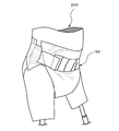
- Patent Document 5 as an absorbent article, an abdominal panel that can be bent between panels, a crotch panel, a back panel, and an outer edge panel are arranged at intervals, and each panel is a single absorbent core panel as a whole. Is held as. Each panel is configured to be able to bend in the front, rear, left and right directions independently within each panel surface. Therefore, as shown in FIG. 33, gaps C1 and C2 may be generated between the skin surfaces 120S of the model 120 at the bent portions B1 and B2 between the panels 121 and 122 and between the panels 121 and 122 when worn. is there.
- the object of the present invention is to improve the feeling of wearing and improve liquid diffusibility and liquid absorbency while maintaining excellent body compatibility even when walking or sitting. Further, it is an object of the present invention not to significantly reduce these performances even in repeated excretion.
- the present invention is divided into a first absorbent part of an intermediate part in which the absorbent body is divided into three in the longitudinal direction, a second absorbent part divided on one side of the first absorbent part, and a second absorbent part on the other side of the first absorbent part
- Each of the absorbing parts is continuous with the liquid receiving layer part on one side of the liquid receiving layer part, and a liquid receiving layer part that absorbs the liquid and diffuses in the plane direction.
- a projecting liquid absorption storage section that is separately distributed and absorbs and stores the liquid, and has a recess recessed in a groove shape on one surface or in a position opposite to both surfaces,
- the concave portion is disposed between the projecting liquid absorbing and storing portions, and the first concave portion disposed in the first absorbing portion is disposed in the longitudinal direction inside the outer edge of the first absorbing portion in plan view, and 2, the second and third recesses arranged in each of the third absorption parts are respectively arranged obliquely with respect to the longitudinal direction, and the same as the first and second recesses.
- the first and third recesses are formed as continuous recesses, or the first recess, the second recess, and the third recess are separated from each other, and the protruding liquid absorption storage part is more than the recess.
- the liquid receiving layer portion at the bottom of the concave portion solves the above problems by an absorbent body having a lower basis weight and density than the protruding liquid absorption storage portion.
- the absorbent body of the present invention is capable of diffusing liquid over a wide range by improving liquid diffusibility, and also diffusing the liquid supplied to the absorbent body in the plane direction with a low-density liquid receiving layer part, Since the diffused liquid can be absorbed and stored in a high-density protruding liquid absorption storage part that is continuous with the liquid receiving layer part, the amount of liquid absorption increases and the absorption performance can be improved.
- each absorption part is easy to change so as to fit the body shape well by the second and third recesses while expressing softness such as flexibility by the first recess, and the necessity for the skin surface of each absorption part Because the adhesion at the part to be raised is improved, it is excellent in body shape compatibility even when walking or sitting.
- the absorbent article of the present invention is excellent in body conformity even when walking or sitting because the adhesiveness at the required portion of each absorbent portion with respect to the skin surface is enhanced.
- the side edge part of an absorber becomes easy to fit a shading part by a 1st recessed part, the side leakage of the liquid supplied to the 1st absorption part can be prevented.
- the upper surface side of the protruding liquid absorption storage part is arranged on the skin contact surface side, and the liquid receiving layer part side is on the non-skin contact surface side By arranging, the feeling of stickiness to the skin can be reduced. Furthermore, since the protruding liquid absorption storage part is continuous with the liquid receiving layer part, it is reduced that the protruding liquid absorption storage part is lifted, and the protruding liquid absorption storage part is not lifted. Is eliminated and the feeling of wearing becomes better.
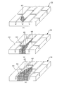
- the absorbent body 10 (10A) of the present invention includes a liquid-receiving layer part 31 that once receives a liquid, and a continuous surface of the liquid-receiving layer part 31 on one side of the liquid-receiving layer part 31. And it has the protrusion liquid absorption storage part 32 distribute
- the protruding liquid absorption storage part 32 and the recessed part 20 are arranged so that the area ratio of the plurality of protruding liquid absorption storage parts 32 is higher than the area ratio of the recessed part 20.
- the area ratio will be described in detail later.
- the plurality of protruding liquid absorption storage portions 32 absorb and store the liquid diffused in the liquid receiving layer portion 31.
- the plurality of protruding liquid absorption storage parts 32 absorb and store the liquid from the part that directly contacts the liquid.
- the density of the protruding liquid absorption storage part 32 is higher than the density of the liquid receiving layer part 31 below the protruding liquid absorption storage part 32. Therefore, the protruding liquid absorption storage part 32 absorbs liquid from the liquid receiving layer part 31 by capillary force.
- the basis weight of the liquid receiving layer portion 31 is preferably 10 g / m 2 or more and 300 g / m 2 or less, more preferably 30 g / m 2 or more and 200 g / m 2 or less, and particularly preferably 40 g / m 2 or more. 150 g / m 2 or less.
- the basis weight of the protruding liquid absorption storage part 32 is higher than the basic weight of the liquid receiving layer part 31 in the recess as the total basic weight of the liquid receiving layer part 31 in contact with the protruding liquid absorption storage part 32, preferably Is 200 g / m 2 or more and 800 g / m 2 or less, more preferably 300 g / m 2 or more and 700 g / m 2 or less, and particularly preferably 400 g / m 2 or more and 600 g / m 2 or less.
- the basis weight of the protruding liquid absorption storage part 32 can be calculated from the difference in basis weight of the liquid receiving layer part 31 in the recess.
- the basis weight of the protruding liquid absorption storage unit 32 is 100 g / m 2 or more and 600 g / m 2 or less, preferably 200 g / m 2 or more and 600 g / m 2 or less, more preferably 300 g / m 2 or more and 600 g / m 2. 2 or less.
- the density of the liquid receiving layer portion 31 is preferably 0.01 g / cm 3 or more and 0.09 g / cm 3 or less, more preferably 0.02 g / cm 3 or more and 0.07 g / cm 3 or less. If the basis weight of the liquid receiving layer part 31 is too low, the diffusibility in the liquid receiving layer part 31 is low, the liquid accumulates in the vicinity of the urination part, the liquid return amount becomes large, and the liquid easily leaks. If the basis weight of the part 31 is too high, the liquid will not easily move to the protruding liquid absorption storage part 32 and the liquid will easily return.
- the density of the liquid receiving layer part 31 is too low, the capillary force does not work sufficiently, the diffusibility in the liquid receiving layer part 31 decreases, the liquid accumulates in the vicinity of the urination part, and the liquid return amount increases. It becomes easy to leak.
- the density of the liquid receiving layer portion 31 is too high, voids in the liquid receiving layer portion 31 are reduced, so that the amount of liquid to be diffused is reduced and the amount of liquid delivered to the protruding liquid absorption storage portion 32 is reduced. And it becomes easy to leak.
- the density of the protruding liquid absorption storage part 32 is higher than the density of the liquid receiving layer part 31, preferably 0.03 g / cm 3 or more and 0.3 g / cm 3 or less, more preferably 0.05 g / cm 3. 3 or more and 0.2 g / cm 3 or less, particularly preferably 0.06 g / cm 3 or more and 0.15 g / cm 3 or less.
- the density of the protruding liquid absorption storage part 32 is too low, the capillary force hardly acts and it is difficult to guide the liquid that has passed through the liquid receiving layer part 31 to the protruding liquid absorption storage part 32 and it is difficult to hold the liquid. .
- the density of the protruding liquid absorption storage part 32 is higher than that of the liquid receiving layer part 31 and set in the above range.
- the measuring method of basic weight and a density is mentioned later.
- the shape of the protruding liquid absorption storage part 32 is not particularly limited, and an arbitrary shape can be adopted.
- the liquid receiving layer portion 31 and the protruding liquid absorption storage portion 32 are composed of pulp fibers and a superabsorbent polymer (SAP), and the contours thereof are not regular as shown in the figure. It is preferable that the whole is a three-dimensional shape. Further, the vertical and horizontal arrangements of the protruding liquid absorption storage unit 32 are not limited, and are preferably determined as appropriate according to the application.
- the protrusion liquid absorption storage part 32 has a rectangle or trapezoid which is long in the width direction in the longitudinal section, and the area of the surface 32S on the skin contact surface side is the area of the back surface 32B on the non-skin contact surface side. Are the same or smaller.
- the absorbent body 10 of the present embodiment is configured by a set of a large number of separated protruding liquid absorption storage portions 32, the “body compatibility” that fits the undulations on the skin surface is a normal large-sized absorbent body (continuous). Significantly higher than that of the absorber.
- the “tracking ability” that follows the wearer's movement satisfactorily and prevents a partial gap from occurring on the skin is extremely good. According to the present embodiment, it is possible to achieve both such good deformability and good absorption and retention of liquid and the like that are not affected by the deformation.
- the absorber 10 repeats the excretion from the initial excretion, so that the liquid is spread to a wider range, for example, the entire region of the liquid receiving layer 31 or a region close to the entire region by the diffusion action of the liquid receiving layer 31. Spread. Then, the liquid can be absorbed from the liquid receiving layer portion 31 by using the protruding liquid absorption storage portion 32 in the diffused region. Therefore, the amount of liquid absorbed by the absorber 10 is greatly improved.
- the absorption amount of the conventional absorbent body (see Patent Document 1) in which the protruding liquid absorption storage unit is independently arranged is reduced by repeating the discharge from the first discharge.
- the protruding liquid absorption storage parts are separated from each other, so that the liquid does not easily transfer between the protruding liquid absorption storage parts, thereby lowering the liquid permeability, and in particular the liquid transfer from the drainage part to other parts.
- This is thought to be due to the fact that it may not be performed sufficiently.
- the range of use stays in a narrow area around the drainage section and its surroundings, and a large amount of liquid that exceeds the absorption amount is liable to cause liquid return and leakage.
- the excretory part is a part directly receiving excretion of urine, soft stool, menstrual blood or vaginal discharge in the absorber and its vicinity.
- the basic weight and density of each part of the above-mentioned absorber 10 are obtained as follows.
- the basis weight in the planar direction of the absorbent body 10 is obtained as follows. First, when the absorber 10 is viewed in plan, the protruding liquid absorption storage part 32 and the lower liquid receiving layer part 31 are cut out integrally, and the liquid receiving layer part 31 of the concave part 20 is cut out to obtain a mass and a planar size. (Area) is measured and the basis weight is calculated. Moreover, the basic weight of the thickness direction of the absorber 10 is calculated
- the protruding liquid absorption storage part 32 on the liquid receiving layer part 31 is cut out, the mass and the planar size (area) are measured, and the basis weight is calculated.
- the difference from the basis weight of the liquid receiving layer portion 31 of the recess 20 measured previously is the basis weight of the protruding liquid absorption storage portion 32.
- the basis weight of the liquid receiving layer portion 31 below the protruding liquid absorption storage portion 32 is equal to the basis weight of the liquid receiving layer portion 31 below the concave portion 20 adjacent thereto.
- the thickness of the liquid receiving layer portion 31 and the protruding liquid absorption storage portion 32 is the same as that of the liquid receiving layer portion 31 and the liquid receiving portion in the recess 20 from cross-sectional observation using a microscope [Microscope manufactured by Keyence (trade name: VHX-1000)).
- the area ratio of each of the plurality of protruding liquid absorption storage portions 32 and the recesses 20 is obtained as follows. Using the above-mentioned microscope, focusing on the concave portion 20, measuring a range including one or more protruding liquid absorption storage portions 32 and the concave portion 20, binarizing the concave portion from the image, and using the image processing apparatus, the area of the concave portion The ratio is derived, and the difference is the area ratio of the protruding liquid absorption storage unit 32. If necessary, use manual correction of the image analyzer. It is preferable to image the entire absorber at once and obtain the area ratio using an image analysis device.
- a pixel (pixel) Sb of the protruding liquid absorption storage unit 32 in a predetermined region.
- ⁇ Sb the sum ⁇ St of the pixels (pixels) St of the recess 20, or the sum ⁇ Sb + ⁇ St of the absorber pixels (pixels)
- the area ratio is calculated, or the representative area ratios of parts having different area ratios
- the area ratio of the protruding liquid absorption storage unit 32 is ⁇ Sb / ( ⁇ Sb + ⁇ St), and the area ratio of the recess 20 can be calculated by ⁇ St / ( ⁇ Sb + ⁇ St).
- the area ratio is set so that the area ratio of the protruding liquid absorption storage section 32 is higher than the area ratio of the recess 20.
- the area ratio of the recess 20 is 100%-[area ratio (%) of the protruding liquid absorption storage section 32].
- the area ratio of the protruding liquid absorption storage unit 32 is set to 60% to 95%, preferably 60% to 90%, more preferably 65% to 90%, more preferably 70%. It is set to 85% or less. If the area ratio of the protruding liquid absorption storage part 32 is too high, the area ratio of the recess 20 becomes too low, and the amount of liquid absorbed from the bottom of the recess 20 to the liquid receiving layer part 31 decreases, and the liquid receiving layer part.
- the diffusion of the liquid to the entire region 31 is insufficient.
- the area ratio of the protruding liquid absorption storage unit 32 is too low, the amount of liquid that can be stored in the protruding liquid absorption storage unit 32 decreases, and the amount of liquid absorbed as the absorber 10 decreases. Therefore, it is desirable that the area ratio of the protruding liquid absorption storage unit 32 be in the above range.
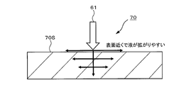
- the liquid 61 passing through the recess 20 is diffused and absorbed from the side surface of the protruding liquid absorption storage unit 32 into the protruding liquid absorption storage unit 32.
- the liquid 61 diffused in the liquid receiving layer portion 31 is diffused from the liquid receiving layer portion 31 into the protruding liquid absorption storage portion 32 by capillary force. In this way, the liquid 61 is stored inside the protruding liquid absorption storage section 32. Since most of the liquid 61 supplied to the surface of the absorbent body 10 diffuses inside the liquid receiving layer portion 31, the protruding liquid absorption storage portion 32 side is defined as the skin contact surface side, and the liquid receiving layer portion 31 side. By using the absorbent body 10 on the non-skin contact surface side, the liquid 61 can be diffused in the liquid receiving layer portion 31 far from the skin side. As a result, the effect of reducing the feeling of stickiness on the skin can be obtained.
- the density of the protruding liquid absorption storage part 32 is higher than the density of the liquid receiving layer part 31, most of the liquid supplied to the absorbent body 10 has a low density liquid receiving layer. It penetrates into the portion 31 and diffuses in the liquid receiving layer portion 31, and is absorbed and stored by the capillary force from the liquid receiving layer portion 31 into the high-density protruding liquid absorption storage portion 32. Moreover, since the protruding liquid absorption storage part 32 is arranged continuously from the liquid receiving layer part 31, the diffusibility due to the presence of the interface when the liquid diffuses from the liquid receiving layer part 31 to the protruding liquid absorption storage part 32.
- the liquid taken in the liquid receiving layer portion 31 without being lowered is smoothly absorbed and stored in the protruding liquid absorption storage portion 32 having a high density by capillary force. Thereby, the absorption performance (absorption amount and absorption speed) of the absorber 10 can be improved.
- the area ratio of the plurality of protruding liquid absorption storage sections 32 is higher than the area ratio of the recesses 20 arranged between the respective protruding liquid absorption storage sections 32, the amount of liquid absorbed in the protruding liquid absorption storage section 32 is reduced. It can be secured sufficiently.
- the absorbent article (not shown) on which the absorbent body 10 is disposed is mounted by arranging a plurality of protruding liquid absorption storage portions 32 so that a part of the absorbent body 10 is blocked.
- the advantage that the adhesion (fitness) to the skin is improved is maintained.
- the protrusion liquid absorption storage part 32 and the liquid receiving layer part 31 form a continuous body, the protrusion liquid absorption storage part 32 is reduced from being swung by a movement of the wearer or the like and prevented from floating.
- the uncomfortable feeling at the time of wearing is eliminated, and the feeling of wearing is remarkably improved.
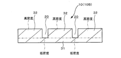
- the absorbent body 10 (10B) of the second embodiment is similar to the absorbent body 10 (10A) of the first embodiment described above, and the liquid receiving layer portion 31, the protruding liquid absorption storage portion 32, and A recess 20 is disposed. Further, the protruding liquid absorption storage part 32 and the concave part 20 are arranged so that the area ratio of the plurality of protruding liquid absorption storage parts 32 is higher than the area ratio of the concave part 20. Further, the density of the protruding liquid absorption storage part 32 is higher than the density of the liquid receiving layer part 31 below, and closer to the density of the liquid receiving layer part 31 at the bottom of the recess 20 than the liquid receiving layer part in the first embodiment. ing.
- the protruding liquid absorption storage part 32 can more easily accept the liquid from the liquid receiving layer part 31 by using the capillary force, and more easily absorb the liquid. Furthermore, the density of the liquid receiving layer part 31 at the bottom of the recess 20 is lower than the density of the protruding liquid absorption storage part 32. It is preferable that the density of the liquid receiving layer part 31 and the protrusion liquid absorption storage part 32 is set to the same value as that of the absorber 10 of the first embodiment described above. Thereby, it becomes easy to absorb the liquid from the liquid receiving layer portion 31 at the bottom of the recess 20.
- the absorbed liquid diffuses in the liquid receiving layer portion 31 and is absorbed into the protruding liquid absorption storage portion 32 from the lower portion of the protruding liquid absorption storage portion 32, so that the liquid absorbability of the absorber 10B is further improved. .
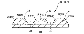
- the absorbent body 10 (10C) of the third embodiment is similar to the absorbent body 10 (10A) of the first embodiment described above, and the liquid receiving layer portion 31, the protruding liquid absorption storage portion 32, and A recess 20 is disposed. Further, the protruding liquid absorption storage part 32 and the concave part 20 are arranged so that the area ratio of the plurality of protruding liquid absorption storage parts 32 is higher than the area ratio of the concave part 20. Further, the density of the protruding liquid absorption storage part 32 is higher than the density of the liquid receiving layer part 31 below. Therefore, the protruding liquid absorption storage part 32 is easy to absorb the liquid from the liquid receiving layer part 31 using the capillary force.
- the density of the side surface of the protruding liquid absorption storage part 32 is lower than the density of the central part of the protruding liquid absorption storage part 32. It is preferable that the density of the center part of the liquid receiving layer part 31 and the protrusion liquid absorption storage part 32 is made into the same value as the absorber 10 of the above-mentioned 1st Embodiment. Further, the density of the side surface of the protruding liquid absorption storage part 32 is set to a value equivalent to the density of the liquid receiving layer part 31 or higher than the density of the liquid receiving layer part 31. It is preferable that the value be lower than the density of the central portion of 32.
- the protruding liquid absorption storage unit 32 has a trapezoidal vertical cross section, but may be rectangular. Moreover, it is preferable to arrange
- the absorbent body 10 (10D) of the fourth embodiment is similar to the absorbent body 10 (10A) of the first embodiment described above, and the liquid receiving layer portion 31, the protruding liquid absorption storage portion 32, and A recess 20 is disposed.
- the protruding liquid absorption storage part 32 and the concave part 20 are arranged so that the area ratio of the plurality of protruding liquid absorption storage parts 32 is higher than the area ratio of the concave part 20.
- the density on the upper side of the protruding liquid absorption storage part 32 is higher than the density of the liquid receiving layer part 31 below. Therefore, the protruding liquid absorption storage part 32 is easy to absorb the liquid from the liquid receiving layer part 31 using the capillary force.
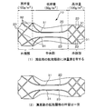
- the liquid-receiving layer portion 31 at the bottom of the concave portion 20 has a larger basis weight at the outer side than the central portion in the longitudinal direction.
- the basis weight of the outer portion becomes larger than the central portion in the longitudinal direction. It is like that.
- the thickness of the liquid receiving layer portion 31 may be increased (the depth of the concave portion 20 is reduced), and in order to reduce the basis weight, the thickness of the liquid receiving layer portion 31 is decreased ( What is necessary is just to deepen the depth of the recessed part 20).
- the liquid taken into the liquid receiving layer portion 31 is easily drawn into the outer portion of the absorber 10D.
- the absorbent body 10D is applied to a diaper as an absorbent article, the liquid excreted is taken in at the central portion of the liquid-receiving layer portion 31 and drawn into both outer portions, so that the amount of taken-in liquid is increased.
- the absorbed liquid can be absorbed by the protruding liquid absorption storage part 32 in the entire absorber 10D, so that the amount of absorption can be improved.
- the density of the liquid receiving layer portion 31 at the bottom of the concave portion 20 is lower than the density of the protruding liquid absorption storage portion 32 as in the second embodiment.
- the density of the side surface of the protrusion liquid absorption storage part 32 may be lower than the density of the center part of the protrusion liquid absorption storage part 32 like the above-mentioned 3rd Embodiment.
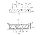
- the absorbent body 10 When the absorbent body 10 is used so that liquid is supplied from the protruding liquid absorption storage section 32 side, a large amount of liquid (particularly liquid with a low viscosity of 5 mm ⁇ Pa ⁇ sec or less such as urine) is discharged. Sometimes the liquid is guided along the recess 20 in the longitudinal direction. This is an effect due to the shape (concave portion) recessed from one surface of the absorbent body 10, and is a result of the liquid flowing into the concave portion 20 and the function as a water channel (see FIG. 8 (1)).
- the projecting liquid of the absorbent body 10 is used.
- the top sheet 16 is disposed on the absorption storage section 32 side, and the back sheet 17 is disposed so as to be bonded around the top sheet 16 and so as to wrap around the liquid receiving layer section 31 side of the absorbent body 10. do it.
- the top sheet 16 is preferably formed of a hydrophilic nonwoven fabric.
- the hydrophilic nonwoven fabric is an air-through nonwoven fabric, a point-bonded nonwoven fabric, a spunbonded nonwoven fabric, a spunlace nonwoven fabric, and a three-dimensionally shaped nonwoven fabric.
- a fiber that has been subjected to a hydrophilic treatment with a composite fiber of polyethylene terephthalate and polyethylene can be preferably used.
- the back sheet 17 is not particularly limited as long as it has waterproofness and moisture permeability.
- a film is formed by melt-kneading a hydrophobic thermoplastic resin, a fine inorganic filler made of calcium carbonate or the like or an incompatible organic polymer, and the film is obtained by uniaxial or biaxial stretching.
- a porous film is mentioned.
- the thermoplastic resin include polyolefin.
- the polyolefin include high to low density polyethylene, linear low density polyethylene, polypropylene, polybutene and the like, and these can be used alone or in combination.
- the skin contact surface side of the absorbent body 10 is covered with a covering sheet. Furthermore, not only the skin contact surface side but also the non-skin contact surface side may be covered with the covering sheet, or the absorbent body 10 may be covered with the covering sheet. Furthermore, it is preferable that a pair of side sheets forming an inner three-dimensional gather is laminated on the skin contact surface side of the top sheet 16. Furthermore, it is preferable that the back sheet 17 and the leak-proof sheet are provided in this order on the non-skin contact surface side.
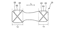
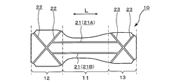
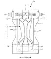
- the absorbent body 10 of the present invention is composed of three parts in the longitudinal direction L of the absorbent body 10. Specifically, the first absorption part 11 divided into the intermediate part, the second absorption part 12 arranged on one side of the first absorption part 11, and the other side of the first absorption part 11 are arranged. And a third absorption portion 13. Therefore, the first absorption part 11 is arranged between the second absorption part 12 and the third absorption part 13.
- the outer shape of the absorbent body 10 may be rectangular, but more preferably, the width direction d (hereinafter referred to as the width direction d is the above) so as to fit the thigh portion of the wearer's thigh.
- the 1st, 2nd, 3rd absorption part 11,12,13 only displayed the area
- the first absorbent portion 11 is disposed on the crotch portion, for example, the second absorbent portion 12 is disposed on the ventral side, and the third The absorption part 13 is arranged on the back side.
- the 2nd absorption part 12 is arranged on the back side
- the first absorbent portion 11 is provided with a plurality of first concave portions 21 (two first concave portions 21 in the drawing), and each first concave portion 21 is inside the side periphery of the first absorbent portion 11 in plan view. It is arranged in the longitudinal direction L.
- a plurality of first recesses 21 are arranged in the first absorption part 11, and only the first recesses 21 are arranged in the first absorption part 11.
- it includes a case where the second concave portion 22 and the third concave portion 23 are partially arranged.
- the phrase “arranged in the longitudinal direction L” includes not only the case of being arranged only in the longitudinal direction L but also the case of being arranged in some other direction.
- second and third recesses 22 and 23 are arranged in each of the second and third absorption parts 12 and 13, and each of the second and third recesses 22 and 23 is arranged in an oblique direction with respect to the longitudinal direction L.
- the second and third recesses 22 and 23 are arranged in the second and third absorption parts 12 and 13, respectively, when only the second and third recesses 22 and 23 are arranged.
- the case where the 1st recessed part 21 is partially arranged is included. It means that it may be arranged in an oblique direction and may be partially arranged in other directions. As a specific example of the oblique direction, it is arranged in an oblique lattice shape as shown in the figure. Accordingly, the first recess 21 is different from the second and third recesses 22 and 23 in the arrangement of the recesses.
- the above oblique direction is defined as follows.
- the measurement starting point is the midpoint position of the portion where the longitudinal center axis CL parallel to the width direction d passing through the longitudinal center of the absorbent body 10 (position of half the longitudinal length) and the first recess 21 intersect.
- the straight line that passes the longest through the first recess 21 is defined as the first line.
- the end of the second recess 22 to be measured that is closest to the edge of the absorbent body 10 is set as the measurement starting point, and the straight line that passes through the second recess is longest.
- the second line direction when the first line and the second line have an intersection angle is defined as an “oblique direction”.
- intersection angle ends at the first line of the first recess 21 that is closest to the edge of the first absorption portion 11 and the position that is closest to the first absorption portion 11 and closest to the widthwise edge of the second absorption portion 12.
- the intersection angle is preferably 10 ° or more and 80 ° or less, more preferably 30 ° or more and 70 ° or less, and most preferably 40 ° or more and 60 ° or less. If the crossing angle is less than 10 °, the abdominal part and the concave part of the back part are arranged in parallel with respect to the longitudinal direction of the absorber. For this reason, a gap is generated between the abdomen and the absorbent body, which easily induces leakage and is inappropriate.
- FIG. 9 shows an example in which the first concave portion 21 and the second and third concave portions 22 and 23 are arranged in a continuous line shape. In the same manner as described above, the first line and the second line can also be defined.
- FIG. (1) When the end of the first recess 21 is linear and the second recess 22 of the connection portion with the first recess 21 is linear, the extension line of the first recess 21 and the second recess 22 form.
- the angle ⁇ is 0 ° ⁇ ⁇ 90 ° or 0 °> ⁇ > ⁇ 90 °.
- the positive angle means a case where the angle with the second concave portion 22 exists outside the extended line of the first concave portion 21, and the negative angle means an inside of the extended line of the first concave portion 21.
- the case where there exists an angle with the 2nd recessed part 22 is said.
- the outer side refers to the end side in the width direction d of the absorbent body 10
- the inner side refers to the center side of the absorbent body 10 in the width direction d. The same applies hereinafter.
- the tangent of the first recess 21 at the connection with the second recess 22 And the second recess 22 is 0 ° ⁇ ⁇ > ⁇ 180 ° or 0 ° ⁇ ⁇ ⁇ 180 °.
- the positive angle means a case where the angle with the second recess 22 exists outside the tangent line of the first recess 21, and the negative angle means that the angle inside the extension line of the first recess 21 is inside. The case where there exists an angle with 2 recessed part 22 is said.
- the tangent line of the first recess 21 at the connection with the second recess 22 is 0 ° ⁇ ⁇ 180 ° or 0 ° ⁇ ⁇ > ⁇ 180 °.
- the positive angle means a case where the angle with the tangent of the second recess 22 exists outside the tangent of the first recess 21, and the negative angle means an inside of the tangent of the first recess 21.
- a line passing through the center position of each width is a line representative of each recess.
- the extension line of the first recess 21 means a line obtained by extending a line passing through the center of the first recess 21 in the width direction.
- the tangent line of the first recess 21 means a tangent line passing through the center of the first recess 21 in the width direction.
- connection portion between the first recess 21 and the second recess 22 a connection point between a line passing through the center in the width direction of the first recess 21 and a line passing through the center in the width direction of the second recess 22. (For example, an intersection or a contact).
- the angular relationship is satisfied.
- each of the above relations is the same as above when one or more of the first concave portion 21, the second concave portion 22, and the third concave portion 23 are distributed in a broken line shape or intermittently.
- the positional relationship is as follows. In this case, the lines defining the angles are those extrapolated lines.
- the first recess 21 may be partly disposed on the second and third absorption parts 12 and 13.
- a part of the second recess 22 is arranged on a part of the first absorption part 11.
- a part of the first recess 21 is arranged on a part of the second absorption part 12.
- the third absorber 13 For example, if the boundary between the first and third absorption parts 11 and 13 is a C line, a part of the third recess 23 is arranged on a part of the first absorption part 11.
- the boundary between the first and third absorption parts 13 is a D line
- a part of the first recess 21 is arranged on a part of the third absorption part 13.
- the arrangement relationship of the recesses with respect to the respective absorption units varies depending on the set position of the boundary between the first absorption unit 11 and the second and third absorption units 12 and 13.
- the boundary of each absorption part is A line and C line was shown as an example.
- first and second recesses 21 and 22 and the first and third recesses 21 and 23 are configured as continuous recesses.
- the cross-sectional shape of the first to third recesses 21 to 23 (hereinafter referred to as the first to third recesses 21 to 23) is not limited, but is rectangular or inverted trapezoidal.
- the absorber 10 is comprised with aggregates, such as a fiber like a nonwoven fabric, the outline of the cross-sectional shape of each recessed part is not decided, but is an approximate shape.
- the second and third concave portions 22 and 23 are arranged in an oblique direction with respect to the longitudinal direction, and the second concave portion 22 is inside the second absorbent portion 12 in plan view, and the third concave portion More preferably, 23 is inside the third absorption portion 13 in plan view.
- the first recess 21 is arranged as described above. Therefore, the outer edge portion of the absorbent body 10 is surrounded by the protruding liquid absorption storage portion 32.
- the minimum distance dm between the outer edge of the absorbent body 10 and the outer edge edge of each of the second concave portion 22 and the third concave portion 23 is appropriately determined, and is, for example, 5 mm to 50 mm, preferably 5 mm to It is 40 mm, more preferably 5 mm to 30 mm.
- the first concave portion 21 is arranged in the longitudinal direction L, so that liquid with low viscosity such as excreted urine (5 mPa ⁇ sec or less) is liquid along the concave portion. Is guided in the longitudinal direction. This is an effect due to the shape depressed from one surface of the absorber, and is likely to occur particularly when the amount of liquid to be discharged is large. When a depression is formed on the side of the drainage surface, the liquid will reach the depression and the concave portion will function as a water channel.
- the 1st recessed part 21 is distribute
- arranged to a crotch part is pressed inside by the sticking part inside a thigh at the time of wear.
- the 1st absorption part 11 is bent by the 1st recessed part 21 so that the skin surface side of the absorber 10 may follow a wearer's skin surface, and a clearance gap (space of a wearer's skin and an absorber) is centered in the width direction. It becomes easier to form.
- a part of the first recess 21 arranged in the second and third absorption parts 12, 13 are arranged toward the end face side in the width direction d, and the absorber 10 in that portion is easily bent by the first recess 21 and the second recess 22 or the third recess 23.
- the central axis C is a line along the longitudinal direction that passes through a half position in the width direction (d direction) passing through a half position in the longitudinal direction of the absorbent body 10. From the point of preventing each absorbing portion from floating in a straight line in the direction parallel to the central axis C, the intersecting portion 26 (shown by diagonal lines) indicated by the region where the third recesses 23 arranged in at least two directions described above intersect.
- the intersecting portion 26 is a region where concave portions having different arrangement directions intersect with each other, and is a common region of the concave portions intersecting in this region. Therefore, only one common region exists on a line parallel to the central axis C. That is, two or more common regions do not exist on a line parallel to the central axis C. Thereby, each absorption part becomes easy to bend in each recessed part along a skin surface, and will be in the state which is easy to adhere
- the first recess 21 is inside the absorbent body 10 in plan view and is arranged in the longitudinal direction L, a gap is formed at the center in the width direction, and a tucked portion inside the thigh at the side in the width direction.
- the liquid is supplied to the first absorbent part 11 along the first absorbent part 11 without leaking the liquid in the width direction d of the first absorbent part 11, through the first recess 21 in the longitudinal direction L of the absorbent body 10. 3 It can be made to flow in the direction of 12 absorption parts 13 and 13. Therefore, the 1st recessed part 21 also has a role which prevents a side leak in the 1st absorption part 11.
- the liquid diffusibility is improved while preventing the side leakage, and the liquid is diffused in the second and third absorbers 12 and 13, so that the liquid can be diffused in a wide range of the absorber 10.
- the second and third absorbent parts 12 and 13 are each provided with a recess in the oblique direction with respect to the longitudinal direction L, for example, the absorbent body 10 of the present invention is worn by an infant who does yes. In this case, the liquid is easily diffused into the second absorption part 12 or the third absorption part 13 worn on the lower abdomen when yes is applied.
- the liquid can be diffused over a wide range of the second and third absorption parts 12 and 13 by the second and third concave parts 22 and 23, and the diffused liquid can be diffused into the second and third concave parts 22 and 23. Since the absorber 10 arranged in the part absorbs, leakage from the abdomen can be prevented. Furthermore, since the first and second recesses 21 and 22 and the first and third recesses 21 and 23 are configured as continuous recesses, the liquid supplied to the first absorption unit 11 is It becomes easy for liquid to pass through the second and third recesses 22 and 23 from the nozzle 21. Also from this point, since the liquid diffusibility is improved, the liquid can be diffused in a wide range of the absorber 10.
- the second and third recesses may be extended to the end of the peripheral edge of each absorbing portion as shown in the figure, but are not limited thereto.
- the second recess 22 is inside the second absorption part 12 in plan view
- the third recess 23 is inside the third absorption part 13 in plan view. 2. Since the liquid transmitted through the third concave portions 22 and 23 is blocked by the edge portions of the second and third absorbing portions 12 and 13, side leakage can be prevented.
- the first absorption part 11 is narrower than the second and third absorption parts 12 and 13. That is, the absorber 10 is configured in a shape narrowed in plan view with respect to the second and third absorbers 12 and 13 in the first absorber 11. And it is preferable that the outer periphery of the 1st absorption part 11 and the 2nd, 3rd absorption parts 12 and 13 is comprised in the continuous shape.
- the concave portion is not disposed only on one surface of each absorption portion, but a concave portion that is recessed in a concave shape is disposed at a position where both surfaces of each absorption portion face each other. Also good.
- the structure which the 1st recessed part 21, the 2nd recessed part 22, and the 3rd recessed part 23 spaced apart may be sufficient.
- the first recess 21 and the second recess 22 may be spaced apart
- the first recess 21 and the third recess 23 may be spaced apart.
- the absorbent body 10 of the present invention changes the shape of each absorbent portion along the body shape while maintaining softness, the gap forming property at the crotch center with respect to the skin surface of each absorbent portion and the crotch side Since the adhesion of the part is enhanced, it is excellent in body shape compatibility even when walking or sitting, and a comfortable wearing feeling can be obtained.
- the absorbent body 10 includes a concave portion for diffusing liquid in a plane direction, a liquid receiving layer portion 31 for temporarily holding and transferring the liquid, and a continuous surface of the liquid receiving layer portion 31 on one surface side of the liquid receiving layer portion 31. And a plurality of protruding liquid absorption storage sections 32 that finally hold a plurality of separated liquids.
- first to third recesses 21 to 23 are disposed between each protruding liquid absorption storage part 32 and another adjacent protruding liquid absorption storage part 32.
- first recess 21 an example in which the first recess 21 is arranged is shown as a representative.
- the second and third recesses 22 and 23 shown in parentheses have the same cross-sectional configuration as the first recess 21.
- the absorbent body 10 having such a cross-sectional configuration is not divided by the first to third recesses 21 to 23, the liquid supplied into the first to third recesses 21 to 23 is the first to third recesses 21.
- Osmose permeates the liquid receiving layer part 31 at the bottom of ⁇ 23, and is held by the liquid receiving layer part 31 at the bottom of the protruding liquid absorption storage part 32 disposed on the side of the first to third recesses 21-23.
- the liquid that cannot be held by the liquid receiving layer portion 31 is discharged, the liquid is diffused by the concave portion, guided in the longitudinal direction, and temporarily held by the liquid receiving layer portion arranged there.
- the retained liquid is absorbed from the liquid receiving layer portion 31 and stored in the protruding liquid absorption storage portion 32. Therefore, by setting the side on which the first to third recesses 21 to 23 are formed as the skin contact surface side, most of the liquid can be temporarily held at the position farthest from the skin surface. A feeling of stickiness on the contact surface side is suppressed, and a comfortable wearing feeling can be obtained.
- the first example of the arrangement form of the recesses in plan view shows an example of the arrangement form of the first recesses 21, and as shown in FIG. 13, a plurality of first recesses 21 are long in the first absorption part 11. Arranged in the direction L.
- the first concave portion 21 is arranged in the longitudinal direction L as a whole of the first concave portion 21, and is configured in a linear shape, a curved shape, a broken line shape, or the like as long as it is arranged at least inside the planar view absorber 10. Or a combination of some of them.
- This first example is a basic form of the arrangement of the first recesses 21.
- the first concave portion 21 is arranged in the longitudinal direction L, the liquid supplied to the first absorbing portion 11 is guided to the second and third absorbing portions 12 and 13 through the first concave portion 21. Nature is increased and it becomes easy to diffuse. That is, the diffusibility of the liquid is improved. Furthermore, the lateral end of the liquid supplied to the first absorption unit 11 can be prevented by the first recess 21 being bent by being lifted and bent in the width direction, with the side portions becoming relatively high and closely contacting.
- the second example of the arrangement of the recesses in plan view includes a plurality of recesses of the second recesses 22 (in the illustrated example, the two second recesses 22 ⁇ / b> A and 22 ⁇ / b> B).
- the first recess 21 is connected in the region A1 where the first recess 21 is disposed.
- a plurality of recesses in the illustrated example, two third recesses 23A and 23B) of the third recesses 23 are located in the area A1 where the first recesses 21 (21A and 21B) are arranged. It is connected with.
- the plurality of recesses of each of the second recesses 22 and the third recesses 23 are connected to each other in the region A1 in which the first recesses 21 are arranged, and thus are supplied to the first absorption unit 11.
- the liquid easily diffuses from the region A1 where the first recess 21 is disposed to the second absorption part 12 through the second recess 22 and to the third absorption part 13 through the third recess 23. That is, the diffusibility of the liquid is improved.
- the 2nd recessed part 22 and the 3rd recessed part 23 which are between 1st recessed parts 21A and 21B make gap formation in a crotch part easy, and the 2nd recessed part 22 and the 3rd recessed part 23 which are on the side from the 1st recessed part 21 are
- the end of the absorbent body 10 bends in the recess while being in close contact with the body so as not to cause the above-described pressure on the groin area or hindrance to the movement of the thigh. Part and second and third absorption parts).
- the end of the first concave portion 21 arranged in the first absorbing portion 11 extends to the second and third absorbing portions 12 and 13.
- the second concave portion 22 may be connected to the second absorbent portion 12.
- the third recesses 23 connected to the first recesses 21 may be connected to each other at the third absorption portion 13.
- the 2nd, 3rd recessed parts 22 and 23 are with respect to the longitudinal direction L so that it may return to the 1st absorption part 11 side from the position connected with the 1st recessed part 21 in the 2nd and 3rd absorption parts 12 and 13. May be arranged in an oblique direction.
- the arrangement form of the second and third depressions 22 and 23 will be described as a fourth example of the arrangement form of the depressions in plan view.
- the second and third recesses 22 and 23 are arranged in an oblique direction with respect to the longitudinal direction L, and one end of the second recess 22 reaches the circumferential surface S2 of the second absorption unit 12, and One end of the three recesses 23 reaches the circumferential surface S3 of the third absorption portion 13.
- the fourth example is a basic form of the arrangement form of the second and third recesses 22 and 23.
- the inclination angle of the second and third recesses 22 and 23 with respect to the longitudinal direction L can be determined as appropriate depending on the form of the second and third recesses 22 and 23 because they can take various forms such as a straight line and a curved line. Is done.
- the liquid is easily diffused to the entire area of the second and third absorbers 12 and 13 by the second and third recesses 22 and 23 arranged in this way. Further, when the absorbent body 10 having such a recessed portion arrangement is worn, the second absorbent portion 12 is bent by the second recessed portion 22, and the third absorbent portion 13 is bent by the third recessed portion 23. It becomes easy and it becomes easy to fit the 2nd absorption part 12 or the 3rd absorption part 13 to a shading part. Thereby, the uncomfortable feeling at the time of operation
- the plurality of concave portions of the second concave portion 22 and the third concave portion 23 are connected to each other in the first concave portion 21 and the second and third absorbing portions 12 and 13, and the second concave portions 22 are connected to each other. Since the third recesses 23 are connected to each other, the liquid supplied to the first absorption unit 11 is transferred from the first recess 21 to the second absorption unit 12 through the second recess 22 and through the third recess 23 to the third. It becomes easy to diffuse to the absorption part 13. That is, the diffusibility of the liquid is improved.
- the sixth example of the arrangement of the concave portions in plan view includes a plurality of first concave portions 21 (two first concave portions 21 ⁇ / b> A and 21 ⁇ / b> B in the drawing) arranged in a direction intersecting the longitudinal direction L.
- a communication recess 24 that connects the first recesses 21 is disposed.
- the number of the connecting recesses 24 is two in the illustrated example, the number of the connecting recesses 24 is preferably determined as appropriate.
- the communication recessed part 24 is distribute
- the inclination direction of the communication recess 24A and the communication recess 24B is the same direction.
- the communication recess 24A and the communication recess 24B may be arranged in different directions and at different angles.
- the inclination angle of the communication recess 24 with respect to the longitudinal method L is, for example, 45 °.
- the angle is not limited to 45 °, and may be 30 ° or 60 °, and the angle is appropriately determined.
- one connecting recess 24 may be disposed at a position where the liquid is supplied, and the other connecting recess 24 may be disposed outside the position where the liquid is supplied.
- the connection recessed part 24 may be formed similarly to the 1st recessed part, it squeezes the liquid receiving layer part 31 and the protrusion liquid absorption storage part 32 from a viewpoint of the diffusibility of a liquid and the free formation of a shape.
- the formed compression recessed part may be sufficient. In the squeezed recess, once the liquid retainability is lowered, in addition to the diffusibility at the time of discharging a large amount, it also has the diffusibility of the liquid once held in the liquid receiving layer 31.
- the basis weight of the absorber 10 (liquid receiving layer portion 31) at the bottom of each of the second concave portion 22 and the third concave portion 23 is the first.
- the basis weight of the absorbent body 10 (liquid receiving layer portion 31) at the bottom of the recess 21 is larger.
- the basis weight of the outer portion is larger than the central portion in the longitudinal direction. .
- the thickness of the liquid receiving layer portion 31 may be increased (the depth of the concave portion is reduced), and in order to reduce the basis weight, the thickness of the liquid receiving layer portion 31 is decreased (the concave portion). Deepen).
- the basis weight of the liquid-receiving layer portion 31 at the bottom of the first recess 21 is 10 g / m 2 or more and 300 g / m 2 or less, preferably 30 g / m 2 or more and 200 g / m 2 or less, more preferably 40 g / m. 2 to 150 g / m 2 or less.
- the basis weight of the liquid receiving layer 31 at the bottom of the second and third recesses 22 and 23 is 10 g / m 2 or more and 330 g / m 2 or less, preferably 40 g / m 2 or more and 230 g / m 2 or less. preferably a 50 g / m 2 or more 180 g / m 2 or less.
- the basis weight of the liquid receiving layer portion 31 at the bottom of the second and third recesses 22 and 23 is 10 g / m 2 , more preferably 20 g / m 2 , more preferably 30 g / m2 than the basis weight of the first recess 21. m 2 or more is preferably high.
- the basis weight of the liquid receiving layer 31 at the bottom of the first recess 21 is 50 g / m 2
- the basis weight of the liquid receiving layer 31 at the bottom of the second and third recesses 22 and 23 is 100 g / m 2.
- the liquid taken into the liquid receiving layer part 31 of the first absorption part 11 is easily drawn into the liquid receiving layer part 31 of the second absorption part 12 and the third absorption part 13.
- a liquid drained by the liquid receiving layer portion 31 of the first absorbent portion 11 is taken in, and is taken into the second absorbent portion 12 and the third absorbent portion 13 on both sides.
- the absorbent body 10 of the present invention is configured by combining some of the above-described concave portions. Therefore, the absorbent body 10 of the present invention is excellent in body shape compatibility even when walking or sitting while maintaining softness, and can improve the absorption performance of the entire absorbent body. In addition, it also has the effect of the recesses of the above-described forms. Furthermore, in the cross-sectional configuration, the absorbent body 10 of the present invention is formed by the liquid-receiving layer portion 31 and the protruding liquid absorption storage portion 32. The configuration has the above-described effects, but improves each function.
- the liquid-receiving layer part 31 has a low final holding function, and it is preferable that the superabsorbent polymer has a lower density than the protruding liquid absorption storage part 32 or is not disposed.
- the protruding liquid absorption storage unit 32 is preferably provided with a highly absorbent polymer in order to increase the holding function as compared with the liquid receiving layer part 31, and has a higher density than the liquid receiving layer part 31. More preferred. Note that the liquid receiving layer portion 31 does not have to be formed at the same density in all portions, and in the position overlapping with the protruding liquid absorption storage portion 32, the liquid may be higher in density than each concave portion.
- the density is gradually increasing toward the center part of the protrusion liquid absorption storage part 32 from the periphery of the protrusion liquid absorption storage part 32. preferable.
- the absorbent body 10 of the present invention has a pulp 41 and a water-absorbing polymer 42, and the mass ratio represented by [mass of pulp] / [mass of water-absorbing polymer] is 1/3. It is 1 / 0.01 or less, preferably 1 / 2.5 or more and 1 / 0.1 or less, more preferably 1/2 or more and 1 / 0.5 or less.
- a water-absorbing polymer 42 is dispersed between pulps 41 that are formed by stacking fibers.
- the water absorbing polymer 42 may be disperse
- the water absorption amount of the water-absorbing polymer 42 is 30 g / g or more and 50 g / g or less, preferably 30 g / g or more and 45 g / g or less in terms of physiological saline in consideration of the absorbability of the liquid of the product.
- they are 31 g / g or more and 40 g / g or less, Especially preferably, they are 32 g / g or more and 36 g / g or less.
- the absorbent polymer 42 absorbs water and gels. In order to cause gel blocking, the liquid permeability between gels is deteriorated, and the absorption performance of the absorber is lowered. As shown in FIG. 20, in the absorbent body 10 having a recess (groove 20), even if the water-absorbing polymer 42 causes gel blocking to some extent, the groove 20 (liquid flow path) is not blocked and liquid permeability is ensured.
- the water absorption amount of the water absorbent polymer 42 is set in the above range.
- the absorption amount of the excretory liquid under a predetermined pressure is 20 g / g or more and 40 g / g or less, preferably 20 g / g or more under a pressure of 2 kPa. It is 35 g / g or less, more preferably 21 g / g or more and 30 g / g or less, and particularly preferably 22 g / g or more and 28 g / g or less.
- the pressurization value of 2 kPa is an example of an average pressure when the baby pressurizes the absorbent body 10 when the absorbent body 10 is worn.
- the crosslinking of the polymer is very strong and the gel strength is too high, and (2) the crosslinking of the polymer is very weak and the gel strength is low. May be too low.
- the water-absorbing polymer itself is not easily crushed under pressure, but the ability to absorb the liquid of the water-absorbing polymer is insufficient, so that the amount of absorption under pressure is reduced, and the liquid is the absorber 10. It will not be absorbed inside but will spread and leak.
- the water-absorbing polymer is easily crushed under pressure, and if gel blocking is caused beyond the extent, the absorption rate of the absorbent body 10 is slow, the liquid return amount is large, and the absorption capacity is reduced.
- a water-absorbing polymer having a large amount of absorption under pressure generally has (1) very strong cross-linking of the polymer, and the water-absorbing polymer itself is not crushed under pressure, but the amount of water absorption is small.
- the water-absorbing polymer 42 in which the amount of the excreted liquid absorbed under pressure is set in the above range is moderately cross-linked so that the water-absorbing polymer 42 itself is not easily crushed. Therefore, since the wearer's load is not crushed under the pressure applied to the absorbent body 10 under the condition that the liquid (for example, urine) is discharged, the water-absorbing polymer 42 protrudes inside the groove 20 to be described later and absorbs water.
- channel 20 is block
- a water-absorbing polymer having a low amount of water absorption under pressure tends to be inhibited from swelling if the packing density (corresponding to an uneven distribution state) is high even under a constant load, and the water absorption amount tends to decrease.
- the swelling inhibition can be alleviated to some extent by the space of the recess (groove 20). Therefore, the lower limit of the absorption amount of the water-absorbing polymer 42 under a pressure of 2 kPa is set to the above range.
- the water-absorbing polymer 42 absorbs too much pressure under pressure, the water-absorbing polymer 42 swells to a greater extent, and the recess (groove 20) is buried or closed, and the passage of liquid is repeatedly excreted. Since there is a possibility that it will not be ensured, the upper limit of the absorption amount under a pressure of 2 kPa is set to the above range.
- the thickness of the absorber 10 is not less than 0.5 mm and not more than 20 mm. Preferably, they are 1 mm or more and 10 mm or less, More preferably, they are 1.5 mm or more and 5 mm or less. If the thickness of the absorbent body 10 is too thin, it will be difficult to secure a sufficient amount of absorption and it will be difficult to wear for a long time, and if it is too thick, the fit of the absorbent body to the body (body compatibility) will be reduced. Therefore, the thickness of the absorber 10 was made into the said range.
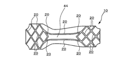
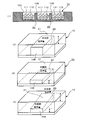
- the absorber 10 has a groove 20 on one side thereof.
- the groove 20 has, for example, a plurality of vertical grooves 20A in the longitudinal direction (Y direction) of the absorber 10, and a plurality of horizontal grooves 20B in the width direction (X direction) orthogonal to the longitudinal direction.
- the lateral grooves 20B are arranged by shifting the arrangement position in the longitudinal direction for each row in the longitudinal direction.
- These vertical groove 20A and horizontal groove 20B are connected to form a continuous groove.
- Various arrangements of the grooves 20 can be employed.
- a part of the grooves 20 may be arranged in an oblique lattice shape or may be a curved shape.
- the depth D of the groove 20 is 20% or more and less than 100% of the thickness T of the absorber 10, preferably 25% or more and 95% or less, more preferably 30% or more and 90% or less, and still more preferably 30. % To 85%.
- a plurality of absorber blocks 44 are separated on the side of the groove 20, and a part of the absorber 10 is left at the bottom of the groove 20.
- the plurality of absorber blocks 44 are connected by the absorber 10 ⁇ / b> B existing at the bottom of the groove 20.
- the depth of the groove 20 is set to the above range.
- the total area of the openings of the groove 20 as viewed in plan with respect to the surface area of the absorber 10 as viewed in plan is 10% or more and 40% or less, preferably 15% or more and 35% or less, and more preferably 20 % To 30%. If the total area of the groove 20 is less than 10%, the amount of liquid that can be passed through the groove 20 is reduced, so that the diffusibility of the liquid is lowered and it is difficult to spread the liquid over a wide area of the absorber 10. On the other hand, if the total area of the groove 20 becomes too large, the diffusibility of the liquid increases, but the volume of the absorbent body 10 that stores the liquid becomes too small, and it becomes difficult to sufficiently absorb the liquid. In addition, the function as a liquid flow path is also reduced.
- the width of the groove 20 is not less than 1 mm and not more than 10 mm, preferably not less than 2 mm and not more than 8.5 mm, more preferably not less than 3 mm and not more than 7 mm. If the width of the groove 20 is too wide, it will not have the function as a groove, and if it is too narrow, the liquid permeability will be reduced and the range in which the liquid will be diffused through the groove 20 will be narrowed. The liquid will be returned to the surface.
- the density of the absorber 10 at the bottom of the groove 20 is preferably lower than the density of the absorber 10 other than the bottom of the groove 20. Since the density of the absorber 10 at the bottom of the groove 20 is made lower than the density of the other absorbers 10 in this way, the liquid supplied into the groove 20 tends to spread in the groove 20 and the absorption at the bottom of the groove 20 is also achieved. It is easily absorbed by the body 10. When the density of the absorber 10 at the bottom of the groove 20 and the density of the absorber 10 at the side wall of the groove 20 are equal, the liquid supplied into the groove 20 flows into the absorber 10 from the bottom and side walls of the groove 20. To be absorbed.
- the density range is set as described above.
- the absorbent body 10 of the present invention has both the high absorption amount and the high absorption speed of the liquid by arranging a plurality of grooves 20 and using the water-absorbing polymer 42 having excellent absorbency even under load. Even in the absorption of the excretion liquid by repeated excretion, the absorption rate is unlikely to decrease, and an excellent effect of exhibiting high absorption performance from the start of use to the end of use is achieved.
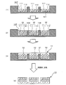
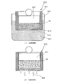
- an example of an absorption process when the drainage liquid is supplied to the absorber 10 described above will be described with reference to FIG.
- an excretory liquid (for example, urine) 60 is supplied to the absorber 10.
- the drainage liquid 60 quickly flows into the groove 20 of the absorbent body 10, and since the flow path of the groove 20 is secured, it quickly travels along the groove 20 and spreads in all directions. Go. At this time, it also diffuses into the absorber 10 at the bottom of the groove 20 and the side wall.
- the absorber block 44 has a higher density than the absorber 10 portion at the bottom of the groove 20, it is diffused into the absorber 10 portion at the bottom of the groove 20. Then, as shown in FIG.
- the drained liquid 60 spreads using the groove 20 as a flow path and is diffused into the absorber 10 portion at the bottom of the groove 20, and is eventually absorbed by the absorber block 44 by capillary force.
- the drained liquid is stored in the absorber block 44 and fixed. In this way, the absorbent body 10 achieves high absorption performance and high absorption speed.
- the liquid absorption amount of the absorber 10 improves by using the water absorbing polymer 42 mentioned above, when it is set as the same absorption amount as a conventional product, the usage-amount of the water absorbing polymer 42 is reduced, Thinning is possible. Therefore, there are also advantages such as thinning and downsizing of an absorbent article using the absorbent body 10 of the present invention. Furthermore, since the groove 20 is provided on one surface side of the absorbent body 10 obliquely in the vertical and horizontal directions, the degree of freedom for deformation of the absorbent body 10 is increased. For this reason, the body suitability of the absorbent body 10 is enhanced, and the liquid can be passed to the end of the absorbent body 10. Therefore, the liquid absorption amount of the absorbent body 10 can be improved.
- the water-absorbing polymer 42 is polymer particles having water absorption, and the production method is not limited.
- the shape is not particularly limited, and may be spherical, lump, grape-like, indefinite shape, porous, powdery or fibrous.
- the average particle diameter of the water-absorbing polymer 42 is 100 ⁇ m or more and 1000 ⁇ m or less, preferably 150 ⁇ m or more and 650 ⁇ m or less, in order to suppress dropping from the product, suppression of movement, and suppression of deterioration in use feeling (roughness). Preferably they are 200 micrometers or more and 500 micrometers or less.
- the water absorption amount of the water-absorbing polymer 42 and the absorption amount under pressure are as described above.
- the water-absorbing polymer 42 polymerizes one or more selected from the following monomers. Moreover, it bridge
- the polymerization method is not particularly limited, and various generally known water-absorbing polymer methods such as a reverse phase suspension polymerization method and an aqueous solution polymerization method can be employed. Thereafter, the polymer is obtained by subjecting the polymer to operations such as pulverization and classification as necessary to adjust the polymer to a desired average particle size and, if necessary, treating with inorganic fine particles.
- the monomer used in producing the water-absorbing polymer 42 is a water-soluble monomer having a polymerizable unsaturated group. Specifically, olefinic unsaturated carboxylic acid or salt thereof, olefinic unsaturated carboxylic acid ester, olefinic unsaturated sulfonic acid or salt thereof, olefinic unsaturated phosphoric acid or salt thereof, olefinic unsaturated phosphate ester And vinyl monomers having polymerizable unsaturated groups such as olefinic unsaturated amines, olefinic unsaturated ammonium salts, and olefinic unsaturated amides.
- Examples of the olefinic unsaturated carboxylic acid or salt thereof include unsaturated carboxylic acids such as acrylic acid, methacrylic acid, maleic acid and fumaric acid, alkali metal salts and ammonium salts thereof.
- olefinic unsaturated carboxylic acid esters examples include 2-hydroxyethyl (meth) acrylate, 2-hydroxypropyl (meth) acrylate, methoxypolyethylene glycol (meth) acrylate, polyethylene glycol mono (meth) acrylate, and phenoxypolyethylene glycol (meth). An acrylate etc. are mentioned.
- olefinic unsaturated sulfonic acids or salts thereof examples include vinyl sulfonic acid, allyl sulfonic acid, styrene sulfonic acid, 2- (meth) acrylamide-2-methylpropane sulfonic acid, 2- (meth) acryloylethane sulfonic acid, 2- (Meth) acryloylpropane sulfonic acid or a salt thereof may be mentioned.
- Examples of the olefinic unsaturated phosphoric acid or a salt thereof include (meth) acryloyl (poly) oxyethylene phosphoric acid ester or a salt thereof.
- Examples of the olefinic unsaturated amine include N, N-dimethylaminoethyl (meth) acrylate, N, N-diethylaminoethyl (meth) acrylate, N, N-dimethylaminopropyl (meth) acrylate, and N, N-dimethylaminopropyl. (Meth) acrylamide etc. are mentioned.
- olefinic unsaturated ammonium salt examples include quaternary ammonium salts of the above olefinically unsaturated amines.
- Examples of the olefinic unsaturated amide include (meth) acrylamide, methyl (meth) acrylamide, N-ethyl (meth) acrylamide, N-propyl (meth) acrylamide, N-isopropyl (meth) acrylamide, N, N-dimethyl (meth) ) (Meth) acrylamide derivatives such as acrylamide, vinylmethylacetamide and the like.
- nonionic hydrophilic group-containing unsaturated monomers such as vinylpyridine, N-vinylpyrrolidone, N-acryloylpiperidine, N-acryloylpyrrolidine, and N-vinylacetamide.
- (meth) acrylate means acrylate or methacrylate
- (meth) acrylamide means acrylamide or methacrylamide
- (meth) acryloyl means acryloyl or methacryloyl.
- olefinic unsaturated carboxylic acids or salts thereof are preferred, acrylic acid, methacrylic acid, alkali metal salts, alkaline earth metal salts or ammonium salts thereof are more preferred, and acrylic acid, alkali metal acrylate salts. (Lithium salt, sodium salt, potassium salt, etc.) and ammonium acrylate are further preferred.
- the absorber manufacturing apparatus 100 has a rotatable fiber pile 101.
- a suction part 102 is arranged in the fiber stacking drum 101.
- a supply unit 103 is provided on the outer peripheral surface of the stacking drum 101 to supply pulp and superabsorbent polymer (SAP), which are constituent materials of the absorbent body 10, on the air.
- SAP superabsorbent polymer
- the supply unit 103 includes a pulp supply unit 104 that supplies pulp by crushing pulp and a polymer supply pipe 105 that supplies superabsorbent polymer, and the outer peripheral surface of the stacking drum 101 that supplies the supplied pulp and superabsorbent polymer. It has a duct 106 for carrying air.
- the fiber stacking drum 101 is partitioned on the drum surface in the shape of an absorbent body, and a fiber stacking cavity 107 is disposed in which the absorbent body is stacked.
- the bottom surface of the stacking cavity 107 has a large number of ventilation holes (not shown), and the air supplied into the stacking cavity 107 is sucked by the suction part 102 through the ventilation holes.
- a non-suction protrusion 108 is provided on the bottom surface of the fiber stacking cavity 107 to provide a recess in the absorber.
- the protrusion 108 has a shape obtained by transferring the shape of the recess disposed in the absorber.
- an unloading means (not shown) for unloading the stacked absorbent body is arranged at the lower part of the stacking drum 101.
- the pulverized pulp and the highly water-absorbing polymer supplied together with the carrier gas (for example, air) by the supply unit 103 are supplied into the fiber stacking cavity 107 and predetermined by the suction force of the suction unit 102.
- the absorber is manufactured by depositing in shape.
- the density of the absorber can be adjusted to a desired density by adjusting the supply amount of pulverized pulp and superabsorbent polymer per hour, the wind speed (wind pressure) at the time of supply, and the like.
- pulverized pulp 111 and superabsorbent polymer 112 are deposited in the stacking cavity 107 disposed on the outer periphery of the stacking drum 101.
- the stacking cavity 107 is arranged on the outer periphery of the stacking drum 101, the bottom surface may be curved along the outer peripheral surface thereof.
- the pulverized pulp 111 and the superabsorbent polymer 112 are further deposited in the stacking cavity 107 to form the protruding liquid absorption storage portion 32.
- the liquid receiving layer portion 31 is formed. Since the protruding liquid absorption storage part 32 and the liquid receiving layer part 31 are continuously deposited in this way, the deposition is completed without generating an interface between the protruding liquid absorption storage part 32 and the liquid receiving layer part 31.
- the absorber 10 can be manufactured.
- the absorber 10 deposited from inside the fiber stack cavity 107 is peeled off, and a pressing process is performed in which only the protruding liquid absorption storage section 32 having a large thickness is pressurized and compressed so that the protruding liquid absorption storage section 32 is A density difference is generated between the liquid receiving layer portion 31 at the bottom of the recess 20 so as to have a high density. Furthermore, the absorber 10 is completed by inverting it up and down, as shown in FIG. Therefore, in the absorber manufacturing apparatus 100, the protruding liquid absorption storage unit 32 is configured first, and then the liquid receiving layer unit 31 is configured continuously.
- the absorbent body 10 manufactured by stacked fiber (deposition) is not particularly limited as a constituent material, but a fiber material, a porous body, a combination thereof, or the like can be used.
- fiber materials include natural fibers such as wood pulp, cotton and hemp, polyolefin resins such as polyethylene and polypropylene, polyester resins such as polyethylene terephthalate, single fibers made of synthetic resins such as polyvinyl alcohol resin, and these resins.
- a composite fiber containing two or more kinds, or a semi-synthetic fiber such as acetate or rayon can be used.
- the fiber may be a heat-shrinkable fiber that changes its shape by heat.
- heat increases the fineness but shortens the fiber length, or heat hardly changes the fineness, but the shape is deformed into a coil shape and the apparent fiber occupies a shorter length. May be.
- a porous body a sponge, a nonwoven fabric, an aggregate of a superabsorbent polymer, or the like can be used.
- the superabsorbent polymer contained in the absorbent body 10 is preferably one that can absorb and hold a liquid that is five times or more of its own weight and can gel.
- the shape is not particularly limited and may be spherical, massive, grape-like, powdery or fibrous.
- the particle size is preferably 1 ⁇ m to 1000 ⁇ m, more preferably 10 ⁇ m to 500 ⁇ m.
- examples of such superabsorbent polymers include polyacrylic acid and its salts and polyacrylate graft weights such as starch, cross-linked carboxymethylated cellulose, polymers or copolymers of acrylic acid or alkali metal acrylates. Coalescence can be mentioned.
- the polyacrylic acid salt a sodium salt can be preferably used as the polyacrylic acid salt.
- acrylic acid may contain a comonomer such as maleic acid, itaconic acid, acrylamide, 2-acrylamido-2-methylpropanesulfonic acid, 2- (meth) acryloylethanesulfonic acid, 2-hydroxyethyl (meth) acrylate or styrenesulfonic acid.
- Copolymers copolymerized within a range that does not deteriorate the performance of the superabsorbent polymer can also be preferably used.
- the absorbent body 10 contains the superabsorbent polymer
- the superabsorbent polymer occupies the mass of the absorbent body 10.
- the proportion is preferably 5% by mass to 95% by mass.
- 10% by mass to 30% by mass is preferable, and in the case of an article that absorbs a high excretion amount of liquid such as a diaper, 50% by mass. It is preferably ⁇ 80% by mass.
- the absorbent body 10 Regardless of whether the absorbent body 10 contains or does not contain a superabsorbent polymer, the absorbent body 10 has a holding amount of 0.9 mass% sodium chloride aqueous solution of 0.1 g or more, particularly 1 g or more, per 1 g of the absorbent body. Is preferable from the viewpoint of expressing stable absorption performance.
- a holding amount As a constituent material of the absorbent body 10, fibers having high hydrophilicity and high capillary force (for example, pulp, rayon, etc.) and not dull even when wet (not plasticized or wet) It is advantageous to use a combination of synthetic fibers (which do not decrease strength) and superabsorbent polymers.
- the protruding liquid absorption storage unit 32 is piled in a state where the density becomes high.
- the protrusion 108 having a height smaller than the depth of the stacking cavity 107 is installed so as to obtain a shape shown in FIG. 26 to be described later, and fluff pulp and superabsorbent polymer are added.
- the protruding liquid absorption storage part 32 is deposited first, and then the liquid receiving layer part 31 is deposited.
- the suction force at the time of deposition of the liquid receiving layer portion 31 is reduced by the influence of the deposit accumulated in the protruding liquid absorption storage portion 32, and the density is lower than that of the protruding liquid absorption storage portion 32.
- the density difference occurs from the top of the protruding liquid absorption storage part 32 to the liquid receiving layer part 31. Further, after the pulp and the superabsorbent polymer are deposited, the deposited absorbent body 10 is peeled from the stacking cavity 107 and pressed.
- the protruding liquid absorption storage section 32 having a large basis weight and thickness, thereby causing a density difference between the protruding liquid absorption storage section 32 and the liquid receiving layer section 31 at the bottom of the recess 20.
- the liquid absorption storage part 32 has a higher density than the liquid receiving layer part 31 at the bottom of the recess 20.
- the absorber 10 (10C) of the said 3rd Embodiment makes the cross-sectional shape of the protrusion part 108 the trapezoid shape in which the fiber drum 101 side becomes a long side, and is the same method as said absorber 10A and 10B. Perform piles. Since the cross-sectional shape of the protruding portion 108 is a trapezoidal shape, the cross-section of the accumulated protruding liquid absorption storage portion 32 becomes a trapezoidal shape having the liquid receiving layer portion 31 side as a long side. Thereby, the top part of the protrusion liquid absorption storage part 32 becomes a trapezoid-shaped upper surface, and the difference in basic weight and thickness arises from a top part to a bottom part.
- the trapezoidal upper surface which is the top of the protruding liquid absorption storage section 32, is actively subjected to pressure, and the central portion of the protruding liquid absorption storage section 32 And a side difference of the protruding liquid absorption storage part 32 cause a density difference.
- the absorbent body 10 having the liquid receiving layer portion 31 on the non-skin contact surface side is produced by inverting the absorbent body 10.
- the height of the protrusion 108 arranged in the fiber stacking cavity 107 shown in FIG. 25 (1) will be described below.
- the center part and outer side part of the absorber 10 demonstrated below are as having demonstrated with the said FIG.
- the fiber stacking cavity 107 corresponding to the portion where the recess 20 is disposed in order to reduce the basis weight of the liquid receiving layer 31 at the bottom of the recess 20 at the center of the absorbent body 10, the fiber stacking cavity 107 corresponding to the portion where the recess 20 is disposed.
- the height of the inner protrusion 108 is set higher than that of the outer portion so that the liquid receiving layer portion 31 is deposited thinner than the outer portion.
- the stacked fibers corresponding to the portion where the recess 20 is disposed in order to increase the basis weight of the liquid receiving layer portion 31 at the bottom of the recess 20 in the outer portion of the absorbent body 10, the stacked fibers corresponding to the portion where the recess 20 is disposed.
- the height of the protruding portion 108 in the cavity 107 is set lower than that of the outer portion so that the liquid receiving layer portion 31 is deposited thickly. Further, as shown in FIG. 25 (4), in the vicinity of the boundary from the central portion to the outer portion of the absorber 10, the height of the protruding portion 108 may be gradually lowered from the central portion toward the outer portion. .
- the pulverized pulp 111 and the superabsorbent polymer 112 are deposited in the stacking cavity 107 in which the protrusion 108 is formed with the thickness of the central portion in the longitudinal direction of the absorber 10 being 2 mm and the thickness of the outer periphery being 1 mm.
- the basis weight of the liquid-receiving layer portion 31 at the bottom of the recess 20 at the center of the absorbent body 10 is 50 g / m 2.
- the liquid receiving layer 31 at the bottom of the recess 20 on the outer side of the body 10 can be deposited thickly so that the basis weight of the liquid receiving layer 31 is 100 g / m 2 .
- the thickness of the liquid receiving layer portion 31 at the bottom of the recess 20 is constant over the entire area of the absorber 10, The basis weight is also constant.
- the diaper 50 has a constricted central portion in the longitudinal direction L corresponding to the crotch portion as a whole.
- the top sheet 16 and the back sheet 17 respectively extend outward from the left and right side edges and both front and rear ends of the absorbent body 10.
- the surface sheet 16 has a width direction d dimension smaller than the width direction dimension of the back sheet 17.
- the diaper 50 is an unfolded diaper, and a pair of fastening tapes FT are attached to both side edges at one end in the longitudinal direction L. Further, a landing tape LT is attached on the back sheet 17 at the other end. It is preferable that the surface sheet 16 is not joined to the concave portion of the absorbent body 10 from the viewpoint that the water-absorbing polymer 42 is easily swelled.
- the diaper 50 includes a three-dimensional gather that can rise above the edge in the width direction d side of the absorbent body 10. That is, a sheet material (side sheet) 18 for a three-dimensional gather having a gather elastic member 56 is arranged on each side of the diaper 50 in the longitudinal direction L to form a three-dimensional gather. Further, on one side of the diaper 50 in the longitudinal direction L, a pair of right and left leg elastic members 58 and 58 (two in this drawing) for leg gathers are arranged to form a leg gather. Yes.
- the leg elastic members 58 for leg gathers are arranged substantially linearly in an extended state in the leg flaps extending outward from both side edges in the longitudinal direction of the absorbent body 10. In this case, the longitudinal direction L in the diaper 50 and the longitudinal direction L in the absorbent body 10 are the same direction.
- the sheet material 18 for three-dimensional gathers has one or more gather elastic members 56 (three in the drawing) fixed to one side edge in an extended state.
- the sheet material 18 is joined to the surface sheet 16 along the longitudinal direction L of the diaper 50 at positions outside the left and right side edges of the absorbent body 10 in the width direction d, and the joined portion is a three-dimensional gather. It is a rising base.
- the sheet material 18 extends outward in the width direction d of the diaper 50 from the rising base end portion, and is joined to the back sheet 17 at the extended portion.
- the sheet material 18 is bonded onto the top sheet 16 at the front and rear end portions in the longitudinal direction L of the diaper 50.
- a liquid-impermeable or water-repellent and moisture-permeable material is preferably used.
- the sheet material 18 include a liquid-impermeable or water-repellent porous resin film, a liquid-impermeable or water-repellent nonwoven fabric, or a laminate of the porous resin film and the nonwoven fabric.
- the nonwoven fabric include thermal bond nonwoven fabric, spunbond nonwoven fabric, SMS nonwoven fabric, and SMMS nonwoven fabric.
- the basis weight of the sheet material 18 is preferably 5 g / m 2 to 30 g / m 2 , more preferably 10 g / m 2 to 20 g / m 2 .
- the surface sheet 16 various kinds of conventionally used diapers of this type can be used, and there is no limitation as long as it can transmit a liquid such as urine, and the liquid is permeable to the skin. It is preferably made of a soft material that hits the center. Examples thereof include woven fabrics and nonwoven fabrics made of synthetic fibers or natural fibers, and porous sheets. As an example, a non-woven fabric made of natural fibers such as cotton or a non-woven fabric made of various synthetic fibers subjected to a hydrophilic treatment can be used.
- a core-sheath structure type including side-by-side type
- composite fiber using polypropylene or polyester as a core component and polyethylene as a sheath component is formed into a web by carding, and then nonwoven fabric ( Thereafter, a predetermined portion may be subjected to a hole opening treatment).
- an apertured sheet made of polyolefin such as low density polyethylene can also be preferably used.
- the back sheet 17 various types conventionally used in this type of diaper can be used, and a liquid-impermeable or water-repellent and moisture-permeable sheet is preferably used.
- a liquid-impermeable or water-repellent and moisture-permeable sheet is preferably used.
- seat material 18 for solid gather formation mentioned above can be used.
- a film made of a synthetic resin such as polyethylene in which fine powder made of a filler such as calcium carbonate is dispersed is stretched, and a porous film having fine holes is used. It is preferable.
- the width of the back sheet 17 is set to be approximately the same as the width of the absorbent body 10 and is disposed on the non-skin contact surface side of the absorbent body 10.
- the non-skin contact surface is a surface directed toward the clothing side (the side opposite to the wearer's skin side) when the diaper is worn.
- the term skin contact surface may be used, and the skin contact surface is a surface directed toward the wearer's skin when the diaper is worn.
- side sheets include non-woven fabrics, film sheets, and paper. From the viewpoint of leakage prevention, it is preferable that the side sheet is formed of a liquid non-permeable or hardly permeable hydrophobic nonwoven fabric, a leakage-proof film sheet, or the like. One sheet may be used, or two or more sheets may be combined with a functional sheet.
- an intermediate sheet 19 (mounting paper) may be disposed between the top sheet 16 and the absorber 10.
- the intermediate sheet 19 include those that have the function of drawing and diffusing excreted liquid, those that reduce the amount of liquid return, those that suppress leakage of the water-absorbing polymer, and those that suppress collapse of the absorbent body. Used.
- seat which has such performance the nonwoven fabric and film which contain the fiber which has hydrophilic property, or was processed with the hydrophilic oil agent etc., or a porous body etc. are mentioned, for example.
- the fibers for the intermediate sheet include (1) natural cellulose fibers such as wood pulp such as softwood kraft pulp and hardwood kraft pulp, and non-wood pulp such as cotton pulp and straw pulp, and (2) regenerated cellulose fibers such as rayon and cupra. (3) Hydrophilic synthetic fibers such as polyvinyl alcohol fibers and polyacrylonitrile fibers, (4) Synthetic fibers such as polyethylene terephthalate (PET) fibers, polyethylene (PE) fibers, polypropylene (PP) fibers, and polyester fibers. These can be used, and these can be used alone or in combination of two or more.
- natural cellulose fibers such as wood pulp such as softwood kraft pulp and hardwood kraft pulp, and non-wood pulp such as cotton pulp and straw pulp
- Hydrophilic synthetic fibers such as polyvinyl alcohol fibers and polyacrylonitrile fibers
- Synthetic fibers such as polyethylene terephthalate (PET) fibers, polyethylene (PE) fibers, polypropylene (PP) fibers, and polyester fibers
- the intermediate sheet 19 for example, paper such as tissue paper, woven fabric, non-woven fabric, knitted fabric, parchment, papyrus, pulp piled fiber, and the like can be used.
- the nonwoven fabric include a chemical bond nonwoven fabric, a thermal bond nonwoven fabric, an airlaid nonwoven fabric, a spunlace nonwoven fabric, a spunbond nonwoven fabric, a melt blown nonwoven fabric, a needle punch nonwoven fabric, and a stitch bond nonwoven fabric.
- These sheets may be in a single layer state or may have a multilayer structure in which a plurality of layers are laminated to form a single sheet.
- a stretchable sheet for example, a non-woven fabric (elastic non-woven fabric) including a fiber containing an elastic resin as a constituent fiber, a film containing an elastic resin (elastic film), or a foaming means forms a three-dimensional network in the structure
- an elastic porous body made of an elastic resin.
- the basis weight of the intermediate sheet 19 is preferably 5 g / m 2 or more and 80 g / m 2 or less, particularly preferably 10 g / m 2 or more and 30 g / m 2 or less.
- the thickness is preferably 0.05 mm or greater and 5.0 mm or less, and particularly preferably 0.1 mm or greater and 3.0 mm or less.
- the intermediate sheet 19 may be disposed only between the top sheet 16 and the absorbent body 10, or may be disposed between the absorbent body 10 and the back sheet 17, and encloses the absorbent body 10. It may be arranged in such a way.
- the material of the surface sheet 16, the absorber 10 and the back surface sheet 17 of the said embodiment, the conditions in a manufacturing method, and the dimensional specification of a product are not specifically limited, The various materials normally used can be used.
- This diaper 50 can be used in the same manner as a normal unfolded diaper.
- This diaper 50 is complicated by using a stretchable sheet for the liquid-receiving layer portion 31 serving as a base sheet of the absorbent body 10 by using the absorbent body 10 to achieve both a high absorption amount and a comfortable wearing feeling.
- Human body compatibility that deforms according to the undulating skin surface and abuts on the surface without gaps, and motion tracking that deforms according to the movement of the wearer's body and maintains the state in contact with the skin surface and the surface Have.
- a plurality of first recesses are formed from the viewpoint of diffusibility and fit.
- the width of the recesses is larger than 2 mm to 5 mm, for example, 15 mm to 20 mm. The effect of can be produced.
- the absorbent article is not limited to the above-described embodiment, and can be applied to this type of absorbent article, for example, disposable diapers, incontinence pads, incontinence liners, and the like. Moreover, even if the said absorbent article is for infants, it is applicable even if it is for adults. Furthermore, it is effective not only for urine but also for menstrual blood, orimono, loose stool and the like.
- the top sheet 16, the absorbent body 10, the back sheet 17, and the side sheet members may be appropriately incorporated in accordance with the use and function.
- the material of the surface sheet 16, the absorber 10 and the back surface sheet 17 of the said embodiment, the conditions in a manufacturing method, and the dimensional specification of a product are not specifically limited, The various materials normally used can be used.
- Example 1 The absorber 10 of Example 1 was produced as follows. First, the protrusion part 108 having a height of 2 mm was arranged so as to obtain the shape shown in FIG. 26 with respect to the stacking cavity 107 having a depth of 6 mm. The cross-sectional shape of the protrusion 108 is a rectangle. Then, fluff pulp (made by Warehauser, trade name NB416) and superabsorbent polymer (made by Nippon Shokubai, trade name W101) were deposited in the stacking fiber cavity 107.
- fluff pulp made by Warehauser, trade name NB416
- superabsorbent polymer made by Nippon Shokubai, trade name W101
- the basis weight of the protruding liquid absorption storage part 32 is 200 g / m 2 for the pulp and 320 g / m 2 for the superabsorbent polymer, and the basis weight of the liquid receiving layer part 31 at the bottom of the recess 20 is 50 g for the pulp. / M 2 , the superabsorbent polymer is 50 g / m 2 .
- the deposited absorbent body 10 was peeled from the stacking cavity 107 and pressed at a pressure of 0.025 MPa.
- the absorbent body 10 was inverted and arranged so as to have the liquid receiving layer portion 31 on the non-skin contact surface side, and the whole was covered with a tissue having a basis weight of 16 g / m 2 .
- Example 2 The absorbent body 10 of Example 2 was manufactured in the same procedure as in Example 1 except that the height of the protrusion 108 was 2 mm at the center in the longitudinal direction of the absorber and 1 mm at the outer side.
- the absorbent body of Comparative Example 1 performs fiber filling in the same manner as in Example 1 except that the height of the protrusion 108 is set to 6 mm for the fiber stacking cavity 107 having a depth of 6 mm, and does not have a liquid receiving layer portion.
- Comparative Example 2 Similarly to Comparative Example 1, the absorbent body of Comparative Example 2 performs fiber filling in the same manner as in Example 1 except that the height of the protruding portion 108 is set to 6 mm for the fiber stacking cavity 107 having a depth of 6 mm.
- An independent block was obtained without a layer. After the obtained block was arranged in the shape shown in FIG. 26 on a pulp sheet having a basis weight of 50 g / m 2 prepared in a separate process, the whole was covered with a tissue having a basis weight of 16 g / m 2. did.
- the kink ratio of the absorber 10 was calculated
- the walking test apparatus 200 is made by imitating a human body shape, for example, imitating from the upper abdomen to the thigh, and the thigh performs the same operation as human walking. It is. As for the walking conditions, first, walking was performed for 1 minute at a walking speed of 120 steps per minute.
- physiological saline was supplied to the absorber at a supply rate of 8 g per second, and walking was further performed for 10 minutes at a walking speed of 120 steps per minute.
- the physiological saline supply and 10-minute walking were taken as one set, and 5 sets were repeated continuously.
- a total of 40 g of physiological saline is supplied to the absorber.
- the floating state of the protrusion liquid absorption storage part of an absorber was confirmed by visual observation.
- the liquid return amount of the absorber was determined as follows. Place a cylinder with an inner diameter of 35 mm at the center in the longitudinal direction and the width in the center of the absorbent body, and maintain the liquid so that the height from the position of the absorbent body into which the liquid is injected is 10 mm, while using physiological saline as the liquid 40 g was injected. At the bottom of the cylinder, an acrylic plate (thickness 5 mm, length 250 mm, width 100 mm) is provided with a size that can cover the entire product. Ten minutes after the start of absorption, 40 g is injected again by the same method. This operation was repeated four times, and a total of 160 g of physiological saline was absorbed by the absorber.
- a filter paper Advanced Materials No.
- Liquid return amount (g) mass of filter paper after pressurization (W2) ⁇ mass of first filter paper (W1) Table 1 shows the dripping rate, the floating state of the protruding liquid absorption storage unit, and the measured liquid return amount.
- the kink rate is reduced and the protruding liquid absorption storage part is lifted more than the absorbent body in which the protruding liquid absorption storage part is arranged independently.
- the liquid return amount was reduced to 33% to 77%, and the effect of maintaining a smooth feeling at the time of wearing was obtained even after the liquid was absorbed.
- the amount of liquid return was further reduced by making the basis weight of the outer portion in the longitudinal direction higher than the basis weight of the central portion.
- the average particle size is calculated by classifying 100 g of the water-absorbing polymer using a sieve according to JIS Z-8801-1982, and determining the average particle size from the mass fraction of each fraction.
- the water absorption was measured at room temperature (20 ⁇ 5 ° C.) and 1.00 g of the water-absorbing polymer was swollen in 150 mL of physiological saline (0.9% NaCl aqueous solution, manufactured by Otsuka Pharmaceutical) at room temperature (20 ⁇ 5 ° C.) for 30 minutes. Then, it is put in a 250 mesh non-woven bag, dehydrated at 143 G for 10 minutes with a centrifuge, and the total mass (total mass) after dehydration is measured. And according to following Formula (1), the holding
- the remaining amount of the nonwoven fabric bag liquid (the weight of the nonwoven fabric bag after centrifugal dehydration) ⁇ (the weight of the nonwoven fabric bag).
- a measuring apparatus that performs a method for measuring the amount of absorption under pressure will be described.
- a column 210 is prepared in which a mesh 213 (250 mesh) is attached to a lower end opening 212 of a vertically arranged cylinder 211 (inner diameter 30 mm).
- 0.500 g of water-absorbing polymer 42 (particles) is put so as to have a uniform thickness.
- a weight 221 (a weight to which a pressure of 2.0 kPa is applied) slightly smaller than the outer diameter of 30 mm is placed on the water-absorbing polymer 42.
- the water-absorbing polymer I was synthesized as follows.
- Synthesis Example 1 a SUS304 5 L reaction vessel (using anchor blades) equipped with a stirrer, a reflux condenser, a monomer dropping port, a nitrogen gas inlet tube, and a thermometer was used as a dispersant.
- Sodium lauryl ether sodium sulfate (trade name EMAL 20C) 0.11% [to acrylic acid mass] was charged, and 1600 mL of cyclohexane was added. The mixture was stirred under a nitrogen atmosphere, and the temperature was raised to an internal temperature of 77 ° C.
- a titanium citrate aqueous solution (50% citric acid and titanyl sulfate aqueous solution were mixed at a mass ratio of 20/27) was prepared.
- Monomer A is prepared by adding 7.2 g of initiator (A) aqueous solution to monomer aqueous solution A
- monomer B is prepared by adding 7.2 g of initiator (A) aqueous solution and 1.5 g of titanium citrate aqueous solution to monomer aqueous solution B.
- 10.5 g of the initiator (B) aqueous solution and 3 g of the titanium citrate aqueous solution were added to the monomer aqueous solution C to prepare monomer C.
- azeotropic dehydration is performed using a dehydrating tube, the water content of the water-absorbing polymer (hydrogel) is adjusted to 60%, and ethylene glycol diglycidyl ether manufactured by Nagase Kasei Kogyo Co., Ltd. (product) (Name Denacol EX-810) 0.33 g dissolved in 10 g of water was added.
- the water-absorbing polymer II was synthesized as follows.
- 0.33 g of ethylene glycol diglycidyl ether (trade name Denacol EX-810) manufactured by Nagase Kasei Kogyo Co., Ltd. was changed to 0.18 g as a crosslinking agent in Synthesis Example 1 described above, and a water-absorbing polymer was used. Obtained.
- 1% of a quaternary ammonium salt (trade name Cotamine 86W) manufactured by Kao Corporation (based on the heavy mass of the water-absorbing polymer) was added with water dilution and dried. After removing coarse particles with a sieve having an opening of 850 microns, 100 parts of the polymer particles are dry blended with 0.5 part of the product name Aerosil 200 manufactured by Nippon Aerosil Co., Ltd. Obtained.
- Synthesis Example 3 the water-absorbing polymer III was synthesized as follows.
- Synthesis Example 3 is the same as Synthesis Example 2 except that 0.18 g of ethylene glycol diglycidyl ether (trade name Denacol EX-810) manufactured by Nagase Kasei Kogyo Co., Ltd. was changed to 0.25 g as a crosslinking agent. The water-absorbing polymer III was obtained.
- the water-absorbing polymer IV was synthesized as follows.
- a SUS304 5L reaction vessel (using anchor blades) equipped with a stirrer, reflux condenser, monomer dropping port, nitrogen gas inlet tube, thermometer, and sodium polyoxyethylene lauryl ether sulfate (manufactured by NOF Corporation) as a dispersant.
- (Trade name Persoft EL) 0.06% [heavy weight of acrylic acid] and stearoyl methyl taurine sodium (trade name Nikkor SMT) manufactured by Nikko Chemicals Co., Ltd. 0.04% [weight of acrylic acid] were charged, and 1600 mL of heptane was added. added. The mixture was stirred under a nitrogen atmosphere and the temperature was raised to an internal temperature of 88 ° C.
- monomer aqueous solution D was divided into three parts, 264 g (hereinafter referred to as monomer aqueous solution E) and 528 g (hereinafter referred to as monomer aqueous solution F).
- a titanium citrate aqueous solution (50% citric acid and titanyl sulfate aqueous solution were mixed at a mass ratio of 20/54) was prepared.
- Prepare monomer A by adding 2.3 g of initiator (C) aqueous solution to monomer aqueous solution D, and prepare monomer E by adding 6.9 g of initiator (C) aqueous solution and 1.5 g of titanium citrate aqueous solution to monomer aqueous solution E.
- 10.5 g of the initiator (D) aqueous solution and 3 g of the titanium citrate aqueous solution were added to the monomer aqueous solution F to prepare monomer F.
- azeotropic dehydration is performed using a dehydrating tube, the water content of the water-absorbing polymer (hydrogel) is adjusted to 60%, and ethylene glycol diglycidyl ether (trade name) manufactured by Nagase Chemical Industries, Ltd. is used as a crosslinking agent.
- Table 1 shows the average particle diameter, water absorption, and absorption under 2 kPa pressure of each of the water-absorbing polymers I, II, III, and IV in Synthesis Examples 1 to 4 described above.
- Example 3 In Example 3, the same operation as in Example 2 was performed, except that the superabsorbent polymer used in Example 2 was the water-absorbing polymer III of Synthesis Example 3.
- the mass ratio represented by [mass of pulp] / [mass of water-absorbing polymer] was 1 / 1.6.
- the thickness of the absorber was 3 mm and the depth of the groove was 2 mm.
- the density of the block portion is 0.2 g / cm 3
- the density of the liquid receiving layer portion of the concave bottom was 0.05 g / cm 3.
- the absorbent body obtained by pressing was placed between the top sheet and the back sheet to obtain an absorbent article.
- the surface sheet which is the skin contact surface, uses the surface material and intermediate sheet of the product name Marys manufactured by Kao Corporation, and the back sheet of the product name Marys manufactured by Kao Corporation is used for the liquid-impermeable back sheet. A sheet was used.
- Example 4-1 was the same as Example 3 except that the superabsorbent polymer used in Example 3 was the water-absorbing polymer IV of Synthesis Example 4.
- Example 4-2 was the same as Example 4-1, except that, in Example 4-1, the absorbent body was inverted and disposed so as to have a liquid-receiving layer portion on the skin contact surface side.
- Example 1 In Reference Example 1, the same operation as in Example 3 was performed except that the superabsorbent polymer used in Example 3 was the water-absorbing polymer I of Synthesis Example 1.
- Reference Example 2 In Reference Example 2, the same operation as in Example 3 was performed except that the water-absorbing polymer II of Synthesis Example 2 was used as the superabsorbent polymer in Example 3.
- Comparative Example 3 Comparative Example 3 is the same as that of Example 4-1, except that the stacking fiber cavity 107 without the protrusions 108 is arranged with the contour shown in FIG. 26, and the spraying amount of the water-absorbing polymer IV is increased by 1.1 times. Then, the same operation as in Example 4-1 was performed to obtain an absorbent article having no recess. Moreover, the thickness of the absorber was 3 mm.
- Example 5 an absorbent article including an absorbent body having the shape shown in FIG. 31 was produced as follows. As shown in FIG. 31 (1), the water-absorbing polymer III obtained in Synthesis Example 3 is used as the water-absorbing polymer 42, and a laminate 43 (with a basis weight of 50 g / m 2) of the pulp sheet 41S and the water-absorbing polymer 42 is used. A three-layer sprayed water-absorbing polymer 42 with a basis weight of 100 g / m 2 for each layer was produced between the four layers of the pulp sheet 41S. As shown in FIG. 31 (1), the water-absorbing polymer III obtained in Synthesis Example 3 is used as the water-absorbing polymer 42, and a laminate 43 (with a basis weight of 50 g / m 2) of the pulp sheet 41S and the water-absorbing polymer 42 is used. A three-layer sprayed water-absorbing polymer 42 with a basis weight of 100 g / m 2 for each layer was produced between the four layers of the pulp sheet 41S. As shown in FIG.
- tissue paper (not shown) having a basis weight of 16 g / m 2 coated with a hot melt agent was placed on the upper side (skin contact surface side) of each absorber block 44 and pressed with a mangle.
- the mass ratio represented by [mass of pulp] / [mass of water-absorbing polymer] was 1 / 1.4.
- the thickness of the absorber was 3 mm and the depth of the groove was 1.5 mm.
- an absorbent body obtained by pressing was placed between the top sheet and the back sheet to obtain an absorbent article.
- For the top sheet that is the skin contact surface use the surface material of the brand name Marys manufactured by Kao Co., Ltd.
- For the liquid-impermeable back sheet use the back sheet of the brand name of Kao Co., Ltd. It was.
- Example 6 As Example 6, when placing the pressed absorbent body between the top sheet and the back sheet in Example 5 described above, the pulp continuous layer was disposed on the top sheet side by reversing the top and bottom.
- Comparative Example 4 As Comparative Example 4, a laminate of the produced pulp and the water-absorbing polymer in Example 5 (water-absorbing polymer III between 4 layers of 50 g / m 2 basis weight pulp sheet at a basis weight of 80 g / m 2 for each layer) A three-layer spray) was cut to a width of 100 mm and a length of 375 mm to obtain an absorbent article. Note that the basis weight of the water-absorbing polymer was lowered by the amount that the area of the absorber was wider than that in Example 5, and the amount of water-absorbing polymer used was the same as that in Example 5.
- the mass ratio represented by [mass of pulp] / [mass of water-absorbing polymer] in the absorber was 1 / 1.2, and the thickness of the absorber was 3 mm.
- Comparative Example 5 Comparative Example 5, Reference Example 3, at a basis weight of each layer 90 g / m 2 water-absorbing polymer I between the laminate (basis weight 50 g / m 2 pulp sheets 4 layers of a pulp and water-absorbing polymer prepared A three-layer spray) was cut to a width of 100 mm and a length of 375 mm to obtain an absorbent article.
- the area of the absorber is larger than that of Comparative Example 4, the basis weight of the water-absorbing polymer is lowered, and the amount of water-absorbing polymer used is about 1.13 times that of Example 5.
- the mass ratio represented by [mass of pulp] / [mass of water-absorbing polymer] in the absorber was 1 / 1.4, and the thickness of the absorber was 3 mm.
- an acrylic cylinder having an inner diameter of 35 mm is placed in the longitudinal direction of the absorbent article from the ventral side edge portion at 150 mm and in the width direction at the center, and 40 g of colored artificial urine is applied to the entire absorbent article while applying a load of 2.0 kPa.
- the liquid was injected while maintaining the liquid so that the height was 10 mm.
- an acrylic plate having a size covering the entire absorbent article is provided at the lowermost part of the cylinder. At this time, the time required for absorption was measured (absorption time 1). The shorter the absorption time, the better the performance.
- Liquid return amount (g) Mass of filter paper after pressurization (W2)-Mass of first filter paper (W1)
- the measured absorption rate and liquid return amount were evaluated in three stages according to the following evaluation criteria.
- the case where the absorption time was less than 30 seconds was evaluated as ⁇
- the case where the absorption time was 30 seconds or more and less than 60 seconds was evaluated as ⁇
- the case where the absorption time was 60 seconds or more was evaluated as ⁇ .
- the liquid return amount was less than 1.0 g, “ ⁇ ”, when 1.0 g or more and less than 1.5 g, ⁇ , and when 1.5 g or more, ⁇ .
- Example 3 the first to fourth liquid absorption time was less than 30 seconds.
- Reference Examples 1 and 2 the first to third absorption times were almost the same as those of Examples 3, 4-1, and 4-2, but the fourth absorption time was less than 60 seconds. Met.
- Comparative Example C using an absorber having no groove (concave portion) the test liquid leaked from the portion corresponding to the crotch of the diaper during the third measurement, and the measurement could not be continued. As a result, it was found that the liquid absorption performance of the examples was maintained high from the start of use until the end of repeated absorption.
- the water-absorbing polymer 42 used in the absorbent body 10 of the present invention is, for example, the first urination (urination), the second, the third, the fourth, Even if it is excreted, it does not swell even if the water-absorbing polymer 42 absorbs the excreted liquid (urine), and is not easily crushed by a load. Therefore, the state of the groove 20 at the first excretion is maintained. For this reason, the groove
- the liquid return amount was less than 1.0 g, and Reference Example 1 using a water-absorbing polymer with a small amount of water absorption, a water-absorbing polymer with a low amount of absorption under pressure was used.
- the liquid return amount was 1.0 g or more, and in Comparative Example 3 using an absorber having no groove (concave portion), measurement was impossible as described above.
- the liquid can be passed through the groove 20 in the first to third urination.
- the load of the wearer is applied to the water-absorbing polymer swollen by the third urination, so that the water-absorbing polymer is crushed and protrudes into the groove 20, and in the worst case, the groove 20 Since it is blocked, it becomes difficult to pass through the groove 20. For this reason, in the fourth drainage, it becomes difficult for the drained liquid to flow through the groove 20, so that the liquid cannot be sufficiently diffused and the liquid return amount increases.
- the absorbent polymer used in Examples 3, 4-1, and 4-2 even if the water-absorbing polymer repeatedly absorbs the excretory liquid (urine), it does not swell and is not easily crushed by the load, so that the groove 20 is blocked.
- the drained liquid can be diffused and absorbed throughout the absorber, so that the liquid return amount can be less than 1.0 g.
- the absorption capacities of Examples 3, 4-1, and 4-2 were both 1.0 compared to Comparative Example 3 in which the amount of water-absorbing polymer used was 1.1 times greater than that of Example 4-1. It was found that the absorption capacity was equivalent to that of Comparative Example 3. That is, Examples 3, 4-1, and 4-2 were found to have a sufficient absorption capacity.
- both the high absorption amount and the high absorption speed can be achieved in the repeated absorption of the drainage liquid after long-term use.
- the liquid return amount is small and high absorption performance can be exhibited.
- Example 5 the liquid absorption time was less than 30 seconds at the first time, and the absorption time was less than 60 seconds at the second to fourth absorption.
- Comparative Example 3 obtained an evaluation result almost the same as that of the Example with respect to the absorption time, but Reference Example 4 using a water-absorbing polymer having a low absorption amount under pressure and a groove.
- Comparative Examples 4 and 5 using an absorber that was not used the absorption time after the second time took 60 seconds or more, and the absorption time became longer. As a result, it was found that the liquid absorption performance of the examples was maintained high from the start of use until the end of repeated absorption.
- the water-absorbing polymer 42 used in the absorbent body 10 of the present invention is, for example, the first urination (urination), the second, the third, the fourth, Even if it is excreted, it does not swell even if the water-absorbing polymer 42 absorbs the excreted liquid (urine), so the state of the groove 20 at the first excretion is maintained. For this reason, the groove
- the liquid return amount was less than 1.5 g
- Reference Example 3 using a water-absorbing polymer having a low water absorption amount Reference Example 4 using a water-absorbing polymer having a low absorption amount under pressure
- Comparative Example 4 where the absorbent body did not have a groove the liquid return amount was 1.5 g or more. As a result, it was found that the liquid return amount of each example was small.
- the groove 20 can be passed through the first urination.
- the load of the wearer is applied to the water-absorbing polymer swollen in the first urination, so that the water-absorbing polymer is crushed and protrudes into the groove 20, and in the worst case, the groove 20 Since it is blocked, it becomes difficult to pass through the groove 20.
- the drained liquid becomes difficult or no longer flows in the groove 20, so that the liquid cannot be sufficiently diffused and the liquid return amount increases.
- the liquid return amount can be made less than 1.5 g.
- the absorption capacities of Examples 5 to 6 are all 1.0 compared to Comparative Example 5 in which the amount of the water-absorbing polymer used is 1.13 times higher than that of Example 5, and is equivalent to Comparative Example 5. It was found to be absorption capacity. That is, it was found that each example has a sufficient absorption capacity. Thus, since each Example has sufficient absorption capacity, in each Example, the liquid return amount is less than 1.0 g, whereas in Reference Example 3, the absorption capacity is 0.8. The amount of liquid return increases. Further, in Comparative Example 4, the same amount of the same water-absorbing polymer III as in Example 5 was used, but because it did not have grooves, the absorption capacity as an absorber was lowered to 0.8, and the liquid return amount was become more.
- both the high absorption amount and the high absorption speed can be achieved in the repeated absorption of the drainage liquid after long-term use.
- the liquid return amount is small and high absorption performance can be exhibited.
- the absorbent body 10 of the present invention is not limited to the above-described embodiment, but in addition to the unfolded diapers as described above, pants-type diapers, sanitary shorts, shorts-type napkins, sanitary napkins, incontinence pads, incontinence It can be used for an absorber contained in an absorbent article such as a liner. Moreover, even if the said absorbent article is for infants, it is applicable even if it is for adults. Furthermore, it is effective not only for urine but also for menstrual blood, orimono, loose stool and the like.
Landscapes
- Health & Medical Sciences (AREA)
- Epidemiology (AREA)
- Engineering & Computer Science (AREA)
- Biomedical Technology (AREA)
- Heart & Thoracic Surgery (AREA)
- Vascular Medicine (AREA)
- Life Sciences & Earth Sciences (AREA)
- Animal Behavior & Ethology (AREA)
- General Health & Medical Sciences (AREA)
- Public Health (AREA)
- Veterinary Medicine (AREA)
- Absorbent Articles And Supports Therefor (AREA)
Abstract
吸収体を長手方向に3区分した中間部の第1吸収部と、前記第1吸収部の一方側に区分された第2吸収部と、前記第1吸収部の他方側に区分された第3吸収部とを有し、前記各吸収部は、液体を吸収して平面方向に拡散する受液層部と、該受液層部の一面側に該受液層部に連続して複数に分立して配され液体を吸収して貯える突出液吸収貯蔵部とを有し、かつ、一方の面にまたは両方の面の対向する位置に溝状に窪んだ凹部を有し、前記突出液吸収貯蔵部間に前記凹部が配され、前記第1吸収部に配される第1凹部は平面視した前記第1吸収部の外縁より内側にあって前記長手方向に配され、前記第2、第3吸収部のそれぞれに配される第2、第3凹部はそれぞれ前記長手方向に対して斜め方向に配され、前記第1、第2凹部同士および前記第1、第3凹部同士が連続した凹部に構成されているかまたは前記第1凹部と前記第2凹部および前記第3凹部とが離間されていて、前記突出液吸収貯蔵部は前記凹部よりも面積率が高く、前記凹部底部の前記受液層部は前記突出液吸収貯蔵部より坪量および密度が低い吸収体である。
Description
本発明は吸収体および吸収性物品に関する。
使い捨ておむつ等の吸収性物品においては、各部材の材料や構造を改良し、その機能や着用感の向上が図られてきた。この吸収性物品に適用される吸収体についても、かかる改良を企図して開発がなされ、特に最近では使用状況や物品の種類に応じた機能性を有するものが種々提案されている。
特許文献1には、表面シートと裏面シートとの間でかつ平面方向にわたって、個々に独立した多数の吸収部からなる吸収体が配置され、さらに吸収体と裏面シートとの間に中間シートが配されている吸収性物品が開示されている。この中間シートは、吸収性物品に排せつされた液の引き込みおよび液の拡散機能を有していて、固定点を介して吸収部を固定している。この固定点は、例えば超音波エンボスやホットメルト接着剤等である。したがって、吸収体と中間シートとは、その間に界面が存在し、一体成型されたものになっていない。
また、特許文献2には、実質的に緻密化されていない低密度の区域であるタフト区域と、このタフト区域を相互に分離し包囲するチャンネルとを含み、タフト区域とチャンネルとが連続している吸収性パッドが開示されている。このチャンネルは貯蔵区域と輸送区域とを含み、貯蔵区域はタフト区域より大なる密度を有し、輸送区域は貯蔵区域より大なる密度を有している。また輸送区域は貯蔵区域によって相互に分離され包囲されている。これにより、浸透能力が向上され、柔らかさが付与されている。
特許文献1に開示された吸収性物品では、中間シートに吸収部よりも小面積の固定部を介して吸収部が配置固定されているので、吸収性物品を装着して歩行等の動作を行った場合に、吸収体に「よれ」を生じる場合があり、また吸収部が浮き上がる場合があり、いずれの場合も違和感があった。また、中間シートと吸収部との間に固定部が介在するとともに界面を有しているので、中間シートから吸収体への拡散が固定部や界面に阻害されて不十分になる場合があり、吸収体の吸収性能が十分に引き出されていなかった。また特許文献2に開示された吸収性パッドでは、浸透能力は向上するものの、タフト区域の密度が低く、チャンネル区域の密度が高いため、チャンネル区域からタフト区域への液の拡散が不十分であった。また、通常の吸水性ポリマーでは繰り返しの排せつによる吸収において吸収速度が低下し、高い吸収性能を期待するにはまだ不十分であった。
特許文献3に開示された使い捨ておむつは、透液性表面シートと不透液性裏面シートと、これら両シート間に介在する吸液性コアとを備えている。そして、前胴周り域と、後胴周り域と、これら両域間に位置する股下域とを有し、前胴周り域から股下域を経て後胴周り域へ延びる仮想線に沿って、吸液性コアの少なくとも一部が分割されている。このような使い捨ておむつにおいて、吸液性コアは、粉砕パルプを主体として高吸水性ポリマー粒子を1質量%以上10質量%以下含む第1繊維層および第2繊維層と、繊維層間に配された高吸水性ポリマー粒子を主体として吸液性コア質量の5%以上50%以下を占める粒子層とからなる積層品である。そして第1繊維層の厚みが第2繊維層の厚みの1.5倍以上となっている。分割されている部位における吸液性コアの側面には、第1および第2繊維層と粒子層とがのぞき、分割されて互いに対向する吸液性コアの側面同士の間では、表面シートが側面に沿って垂下して裏面シートに当接し、その当接する部位において表裏面シートが互いに接合している。体液は、吸液性コアの頂面から吸収されるだけではなく、吸液性コアの側面から粒子層や、その粒子層の下側に位置する繊維層にも直接吸収される。それゆえ、このおむつでは、粒子層の吸液能力を有効に利用するだけでなく、この粒子層がゲルブロックを形成した場合でも、粒子層下側の繊維層の吸液能力を有効に利用する。しかし、特許文献3に記載の使い捨ておむつでは、腹部や背部の溝が吸収体の長手方向に沿った状態で入っているため、おむつを装着した場合、腹部と吸収体との間に隙間を生じてしまい、伝い漏れを誘発しやすくなる。
特許文献4に開示された紙おむつは、吸収体中に荷重下での人工尿に対する吸水性に優れる吸水性ポリマーを含んでいる。しかしながら、吸収体に複数の溝が配置されてないので、速い吸収速度を達成することは困難であった。
特許文献5には、吸収性物品として、パネル同士間で屈曲可能な腹部パネルと股部パネルと背部パネルと外縁部パネルとが間隔を置いて配置され、各パネルが全体として1枚の吸収コアパネルとして保持されたものが開示されている。各パネルは、それぞれ独立して各パネル面内で前後左右に屈曲可能に構成されている。そのため、図33に示すように、着用時に、各パネル121、122間、122、123間のそれぞれの屈曲部B1、B2においてモデル120の肌面120Sとの間に隙間C1、C2を生じることがある。
特許文献5に開示された吸収性物品では、着用時に、各パネル間の屈曲部において肌面との間に隙間を生じると、その隙間を通じて液漏れを超こすことがあった。さらに、着用中に違和感を生じることがあった。また特許文献5に開示された吸収性物品では、中間シートと吸収部との間に固定部が介在するとともに界面を有しているので、中間シートから吸収体への拡散が固定部や界面に阻害されて不十分になる場合があり、吸収体の吸収性能が十分に引き出されていなかった。
本発明は、歩行時や座った時などでも優れた体型適合性を維持しつつ、装着感を向上させるとともに、液拡散性と液吸収性を向上させることを課題とする。また、繰り返しの排泄においても、これら性能を著しく低下させないことを課題とする。
本発明は、吸収体を長手方向に3区分した中間部の第1吸収部と、前記第1吸収部の一方側に区分された第2吸収部と、前記第1吸収部の他方側に区分された第3吸収部とを有し、前記各吸収部は、液体を吸収して平面方向に拡散する受液層部と、該受液層部の一面側に該受液層部に連続して複数に分立して配され液体を吸収して貯える突出液吸収貯蔵部とを有し、かつ、一方の面にまたは両方の面の対向する位置に溝状に窪んだ凹部を有し、前記突出液吸収貯蔵部間に前記凹部が配され、前記第1吸収部に配される第1凹部は平面視した前記第1吸収部の外縁より内側にあって前記長手方向に配され、前記第2、第3吸収部のそれぞれに配される第2、第3凹部はそれぞれ前記長手方向に対して斜め方向に配され、前記第1、第2凹部同士および前記第1、第3凹部同士が連続した凹部に構成されているかまたは前記第1凹部と前記第2凹部および前記第3凹部とが離間されていて、前記突出液吸収貯蔵部は前記凹部よりも面積率が高く、前記凹部底部の前記受液層部は前記突出液吸収貯蔵部より坪量および密度が低い吸収体により上記の課題を解決するものである。
本発明の吸収体は、液拡散性が向上することにより、広い範囲に液体を拡散させることができ、また吸収体に供給された液体を密度の低い受液層部で平面方向に拡散し、その拡散した液体を受液層部に連続している密度の高い突出液吸収貯蔵部に吸収させて貯えることができるので、液体の吸収量が多くなり、吸収性能を高めることができる。また第1凹部による可撓性等の柔らかさを発現しつつ、第2、第3凹部により体型によくフィットするように各吸収部の形状が変化しやすく、各吸収部の肌面に対する必要とされる部分での密着性が高められるので、歩行している時や座っている時などでも体型適合性に優れる。
本発明の吸収性物品は、各吸収部の肌面に対する必要とされる部分での密着性が高められるので、歩行している時や座っている時などでも体型適合性に優れる。また第1凹部によって吸収体の側縁部分がそけい部にフィットしやすくなるので、第1吸収部に供給された液体の横漏れを防止できる。さらに肌への密着性(フィット感)が向上できる利点を維持しつつ、突出液吸収貯蔵部の上面側を肌当接面側に配置し、受液層部側を非肌当接面側に配置することで、肌へのべとつき感が低減できる。さらに、突出液吸収貯蔵部は受液層部に連続していることから、着用時の歩行等の動作によってよれることが低減され、突出液吸収貯蔵部が浮き上がることも無くなり、装着時の違和感が解消され、装着感がより良くなる。
本発明の吸収性物品は、各吸収部の肌面に対する必要とされる部分での密着性が高められるので、歩行している時や座っている時などでも体型適合性に優れる。また第1凹部によって吸収体の側縁部分がそけい部にフィットしやすくなるので、第1吸収部に供給された液体の横漏れを防止できる。さらに肌への密着性(フィット感)が向上できる利点を維持しつつ、突出液吸収貯蔵部の上面側を肌当接面側に配置し、受液層部側を非肌当接面側に配置することで、肌へのべとつき感が低減できる。さらに、突出液吸収貯蔵部は受液層部に連続していることから、着用時の歩行等の動作によってよれることが低減され、突出液吸収貯蔵部が浮き上がることも無くなり、装着時の違和感が解消され、装着感がより良くなる。
本発明の上記及び他の特徴及び利点は、適宜添付の図面を参照して、下記の記載からより明らかになるであろう。
本発明に係る吸収体の好ましい一実施形態の第1実施形態について、図1を参照しながら、以下に説明する。
図1に示すように、本発明の吸収体10(10A)は、液体を一旦受け取る受液層部31と、この受液層部31の一面側に該受液層部31に連続して、かつ複数に分立して配された突出液吸収貯蔵部32とを有する。したがって、それぞれの突出液吸収貯蔵部32と隣接する別の突出液吸収貯蔵部32との間に多量の液体を平面方向に拡散する凹部20が配される。この突出液吸収貯蔵部32と凹部20とは、複数の突出液吸収貯蔵部32の面積率が上記凹部20の面積率よりも高くなるように配される。面積率については、後に詳述する。上記複数の突出液吸収貯蔵部32は、受液層部31中を拡散してきた液体を吸収して貯えるものである。もちろん、複数の突出液吸収貯蔵部32は、液体に直接接触する部分からも液体を吸収して貯える。また上記突出液吸収貯蔵部32の密度は突出液吸収貯蔵部32下部の受液層部31の密度よりも高くなっている。したがって、上記突出液吸収貯蔵部32は毛管力により受液層部31から液体を吸収する。
上記受液層部31の坪量は、好ましくは10g/m2以上300g/m2以下であり、より好ましくは30g/m2以上200g/m2以下であり、特に好ましくは40g/m2以上150g/m2以下である。
また、上記突出液吸収貯蔵部32の坪量は、突出液吸収貯蔵部32と接している受液層部31の合計の坪量として凹部にある受液層部31の坪量より高く、好ましくは200g/m2以上、800g/m2以下、より好ましくは300g/m2以上700g/m2以下であり、特に好ましくは400g/m2以上600g/m2以下である。突出液吸収貯蔵部32の坪量は、凹部における受液層部31の坪量の差分より算出できる。
上記突出液吸収貯蔵部32の坪量は、100g/m2以上、600g/m2以下、好ましくは200g/m2以上600g/m2以下であり、より好ましくは300g/m2以上600g/m2以下である。
また、上記突出液吸収貯蔵部32の坪量は、突出液吸収貯蔵部32と接している受液層部31の合計の坪量として凹部にある受液層部31の坪量より高く、好ましくは200g/m2以上、800g/m2以下、より好ましくは300g/m2以上700g/m2以下であり、特に好ましくは400g/m2以上600g/m2以下である。突出液吸収貯蔵部32の坪量は、凹部における受液層部31の坪量の差分より算出できる。
上記突出液吸収貯蔵部32の坪量は、100g/m2以上、600g/m2以下、好ましくは200g/m2以上600g/m2以下であり、より好ましくは300g/m2以上600g/m2以下である。
上記受液層部31の密度は、好ましくは0.01g/cm3以上0.09g/cm3以下であり、より好ましくは0.02g/cm3以上0.07g/cm3以下である。この受液層部31の坪量が低すぎると受液層部31での拡散性が低く、排尿部近傍に液が溜まり、液戻り量が大きくなったり、液漏れしやすくなり、受液層部31の坪量が高すぎると、液が突出液吸収貯蔵部32へ移動しにくくなり、液戻りしやすい。また、受液層部31の密度が低すぎると、毛管力が十分に働かず受液層部31での拡散性が低下し、排尿部近傍に液が溜まり、液戻り量が大きくなったり、漏れやすくなる。一方、受液層部31の密度が高すぎると、受液層部31内の空隙が減少するため、拡散させる液の量が減少し、突出液吸収貯蔵部32への液の受け渡し量が低下して、液漏れしやすくなる。
また、上記突出液吸収貯蔵部32の密度は、受液層部31の密度より高く、好ましくは0.03g/cm3以上0.3g/cm3以下であり、より好ましくは0.05g/cm3以上0.2g/cm3以下であり、特に好ましくは0.06g/cm3以上0.15g/cm3以下である。この突出液吸収貯蔵部32の密度が低すぎる場合、毛管力が作用しにくくなり受液層部31中を通ってきた液体を突出液吸収貯蔵部32へ導き難くなり液体の保持が困難となる。一方、突出液吸収貯蔵部32の密度が高すぎる場合も、超吸収性ポリマー(SAP)が膨潤阻害を起こしやすくなり、受液層部31中を通ってきた液体を保持することが困難となる。よって、突出液吸収貯蔵部32の密度は受液層部31よりも高く上記範囲に設定することが望ましい。なお、坪量および密度の測定方法については、後述する。
また、上記突出液吸収貯蔵部32の密度は、受液層部31の密度より高く、好ましくは0.03g/cm3以上0.3g/cm3以下であり、より好ましくは0.05g/cm3以上0.2g/cm3以下であり、特に好ましくは0.06g/cm3以上0.15g/cm3以下である。この突出液吸収貯蔵部32の密度が低すぎる場合、毛管力が作用しにくくなり受液層部31中を通ってきた液体を突出液吸収貯蔵部32へ導き難くなり液体の保持が困難となる。一方、突出液吸収貯蔵部32の密度が高すぎる場合も、超吸収性ポリマー(SAP)が膨潤阻害を起こしやすくなり、受液層部31中を通ってきた液体を保持することが困難となる。よって、突出液吸収貯蔵部32の密度は受液層部31よりも高く上記範囲に設定することが望ましい。なお、坪量および密度の測定方法については、後述する。
上記突出液吸収貯蔵部32の形状は特に限定されず任意の形状のものを採用することができる。本実施形態において受液層部31と突出液吸収貯蔵部32とはパルプ繊維と超吸収性ポリマー(SAP)とから構成されており、その輪郭は図示したもののように定形的なものでなくてもよく、全体として立体形状のものとされていることが好ましい。また、突出液吸収貯蔵部32の縦横の配列も限定されず用途に合わせ適宜決められるのが好ましい。
突出液吸収貯蔵部32は、その縦断面において幅方向に長い長方形または台形を有しており、その肌当接面側である表面32Sの面積は非肌当接面側である裏面32Bの面積に対して同一または小さくなっている。
本実施形態の吸収体10は、分立した多数の突出液吸収貯蔵部32の集合で構成されているため肌面の起伏にフィットする「身体適合性」が通常の一体型の大きな吸収体(連続吸収体)に比べ大幅に高まる。また着用者の動作にも良好に追随し、肌に対して部分的な隙間が生じたりすることが防止される「動作追随性」が極めて良好である。本実施形態によればこのような良好な変形性と該変形に左右されない良好な液体等の吸収保持との両立を図ることができる。
また、吸収体10は、初回の排せつから排せつを繰り返すことにより、排せつ部から受液層部31の拡散作用により、液をより広い範囲、例えば受液層部31の全域または全域に近い領域まで拡散させる。そして、拡散させた領域の突出液吸収貯蔵部32を利用して受液層部31から液体を吸収することができる。したがって、吸収体10の液体の吸収量が大幅に向上する。
一方、突出液吸収貯蔵部が独立に配された従来の吸収体(前記特許文献1参照)は、初回の排せつから排せつを繰り返すことにより、その吸収量が低下していく。これは突出液吸収貯蔵部どうしが離間していることにより突出液吸収貯蔵部間の液の移行がしにくく、それにより通液性が低下し、特に排せつ部からその他部位への液体の移行が十分に行われない場合があるためと考えられる。その結果、排せつ部およびその周囲の狭い範囲に利用範囲が留まり、吸収量を越えた液が多量に存在して液戻りや漏れを起こしやすくなる。
なお排せつ部とは、吸収体において、尿、軟便、経血もしくはおりもの等の排せつを直接受ける部分およびその近傍である。
なお排せつ部とは、吸収体において、尿、軟便、経血もしくはおりもの等の排せつを直接受ける部分およびその近傍である。
上述の吸収体10の各部の坪量および密度は、以下のようにして求める。
図2に示すように、吸収体10の平面方向の坪量は以下のように求める。まず、吸収体10を平面視して、突出液吸収貯蔵部32とその下部の受液層部31を一体に切り出し、また凹部20の受液層部31を切り出し、質量と平面的な大きさ(面積)を測定し坪量を算出する。
また、吸収体10の厚み方向の坪量は以下のように求める。まず、受液層部31上の突出液吸収貯蔵部32を切り出して質量と平面的な大きさ(面積)を計測し坪量を算出する。先に計測した凹部20の受液層部31の坪量との差が突出液吸収貯蔵部32の坪量となる。ここでは、突出液吸収貯蔵部32の下部の受液層部31の坪量とそれに隣接する凹部20の下部の受液層部31の坪量が同等であるとしている。受液層部31および突出液吸収貯蔵部32の厚さは、マイクロスコープ[キーエンス社製マイクロスコープ(商品名VHX-1000))を使用した断面観察より凹部20における受液層部31と受液層部31と重なった突出液吸収貯蔵部32の厚みを各々計測する。
上記測定結果に基づいて、密度=坪量/厚みなる計算により密度を算出する。
図2に示すように、吸収体10の平面方向の坪量は以下のように求める。まず、吸収体10を平面視して、突出液吸収貯蔵部32とその下部の受液層部31を一体に切り出し、また凹部20の受液層部31を切り出し、質量と平面的な大きさ(面積)を測定し坪量を算出する。
また、吸収体10の厚み方向の坪量は以下のように求める。まず、受液層部31上の突出液吸収貯蔵部32を切り出して質量と平面的な大きさ(面積)を計測し坪量を算出する。先に計測した凹部20の受液層部31の坪量との差が突出液吸収貯蔵部32の坪量となる。ここでは、突出液吸収貯蔵部32の下部の受液層部31の坪量とそれに隣接する凹部20の下部の受液層部31の坪量が同等であるとしている。受液層部31および突出液吸収貯蔵部32の厚さは、マイクロスコープ[キーエンス社製マイクロスコープ(商品名VHX-1000))を使用した断面観察より凹部20における受液層部31と受液層部31と重なった突出液吸収貯蔵部32の厚みを各々計測する。
上記測定結果に基づいて、密度=坪量/厚みなる計算により密度を算出する。
上述の複数の突出液吸収貯蔵部32および凹部20のそれぞれの面積率は以下のように求める。上記マイクロスコープを用いて、凹部20に焦点を合わせて、突出液吸収貯蔵部32と凹部20を1箇所以上含む範囲を計測し、画像から凹部部分を二値化して画像処理装置により凹部の面積率を導き、その差分が突出液吸収貯蔵部32の面積率となる。必要であれば、画像解析装置の手動補正等を使用する。吸収体全体を一度に画像化して画像解析装置により面積率を求めることが好ましいが、複数の画像により計測を行う場合には、例えば、所定領域における突出液吸収貯蔵部32の画素(ピクセル)Sbの総和ΣSb、凹部20の画素(ピクセル)Stの総和ΣSt、吸収体の画素(ピクセル)の総和ΣSb+ΣStのいずれか2つを求め、面積率を算出するか、異なる面積率の部位の代表面積率と各々の部分の面積の全体面積における割合を乗じた数値の合計より求めることができる。突出液吸収貯蔵部32の面積率はΣSb/(ΣSb+ΣSt)となり、凹部20の面積率はΣSt/(ΣSb+ΣSt)で算出できる。
上記面積率は、突出液吸収貯蔵部32の面積率が凹部20の面積率より高くなるように設定される。凹部20の面積率は100%-[突出液吸収貯蔵部32の面積率(%)]となる。例えば、突出液吸収貯蔵部32の面積率は、60%以上95%以下に設定され、好ましくは60%以上90%以下、さらに好ましくは65%以上90%以下に設定され、より好ましくは70%以上85%以下に設定される。上記突出液吸収貯蔵部32の面積率が高すぎると、凹部20の面積率が低くなりすぎて、凹部20の底部から受液層部31への液体の吸収量が少なくなり、受液層部31全域への液体の拡散が不十分となる。一方、突出液吸収貯蔵部32の面積率が低すぎると、突出液吸収貯蔵部32に貯えることができる液体の量が少なくなり、吸収体10としての液体の吸収量が低下することになる。したがって、突出液吸収貯蔵部32の面積率は上記範囲とするのが望ましい。
ここで、上記吸収体10に供給された液体(例えば尿等)の通液、拡散状態について、図3によって詳しく説明する。
図3(1)、(2)に示すように、吸収体10の上方より液体61が供給されると、液体61の大部分は突出液吸収貯蔵部32表面から凹部20内部に流れ込み、凹部20を通って四方に通液される。そのとき、突出液吸収貯蔵部32表面に供給された液体61の一部は突出液吸収貯蔵部32内に直接吸収される。また凹部20を通る液体61の大部分は、凹部20の底部より受液層部31に浸透し、受液層部31内を四方に拡散されて行く。さらに、凹部20を通る液体61の一部は突出液吸収貯蔵部32の側面より突出液吸収貯蔵部32の内部に拡散され吸収される。受液層部31内を拡散した液体61は、毛管力によって受液層部31から突出液吸収貯蔵部32の内部に拡散される。このようにして液体61は突出液吸収貯蔵部32の内部に貯えられる。
吸収体10の表面に供給された液体61の大部分は、上記受液層部31の内部を拡散するので、突出液吸収貯蔵部32側を肌当接面側とし、受液層部31側を非肌当接面側として、吸収体10を用いることにより、肌側から遠い受液層部31で液体61を拡散させることができる。これによって、肌へのべとつき感が少なくなるという効果が得られる。
吸収体10の表面に供給された液体61の大部分は、上記受液層部31の内部を拡散するので、突出液吸収貯蔵部32側を肌当接面側とし、受液層部31側を非肌当接面側として、吸収体10を用いることにより、肌側から遠い受液層部31で液体61を拡散させることができる。これによって、肌へのべとつき感が少なくなるという効果が得られる。
一方、図4に示すように、従来の連続吸収体70では、その表面に液体61が供給された場合、液体61の一部は肌当接面側の表面70Sを流れて四方に拡がっていく。その他の液体61は、連続吸収体70内部に拡散されていく。このため、連続吸収体70では、尿等の液体61が肌当接面側の表面70Sに供給された場合、肌へのべとつき感が生じやすくなる。
上記実施形態の吸収体10では、突出液吸収貯蔵部32の密度が受液層部31の密度よりも高いことから、吸収体10に供給された液体の大部分は、密度の低い受液層部31に浸透して受液層部31内を拡散し、この受液層部31から密度の高い突出液吸収貯蔵部32に毛管力により吸収されて貯えられる。しかも受液層部31から連続して突出液吸収貯蔵部32が配されていることから、受液層部31から突出液吸収貯蔵部32へ液体が拡散するときに界面の存在による拡散性の低下がなく、受液層部31に取り込まれた液体は密度の高い突出液吸収貯蔵部32に毛管力により円滑に吸収され、貯えられていく。これにより、吸収体10の吸収性能(吸収量と吸収速度)の向上が図れる。
また複数の突出液吸収貯蔵部32の面積率はそれぞれの突出液吸収貯蔵部32間に配される凹部20の面積率よりも高くしたことから、突出液吸収貯蔵部32における液体の吸収量を十分に確保することができる。
また、複数の突出液吸収貯蔵部32を配することによって吸収体10の一部がブロック化されていることにより、この吸収体10が配された吸収性物品(図示せず)を装着した際の肌への密着性(フィット感)が向上されるという利点が維持される。さらに、突出液吸収貯蔵部32と受液層部31とが連続体を成すことから、装着者の歩行等の動作によって、突出液吸収貯蔵部32がよれることが低減され、浮き上がることが防止されて、装着時の違和感が解消され、装着感が格段に向上する。
また複数の突出液吸収貯蔵部32の面積率はそれぞれの突出液吸収貯蔵部32間に配される凹部20の面積率よりも高くしたことから、突出液吸収貯蔵部32における液体の吸収量を十分に確保することができる。
また、複数の突出液吸収貯蔵部32を配することによって吸収体10の一部がブロック化されていることにより、この吸収体10が配された吸収性物品(図示せず)を装着した際の肌への密着性(フィット感)が向上されるという利点が維持される。さらに、突出液吸収貯蔵部32と受液層部31とが連続体を成すことから、装着者の歩行等の動作によって、突出液吸収貯蔵部32がよれることが低減され、浮き上がることが防止されて、装着時の違和感が解消され、装着感が格段に向上する。
次に本発明に係る吸収体の第2実施形態について、図5を参照しながら、以下に説明する。
図5に示すように、第2実施形態の吸収体10(10B)は、前述の第1実施形態の吸収体10(10A)と同様に、受液層部31、突出液吸収貯蔵部32および凹部20が配される。また複数の突出液吸収貯蔵部32の面積率が上記凹部20の面積率よりも高くなるように、突出液吸収貯蔵部32および凹部20が配される。さらに上記突出液吸収貯蔵部32の密度はその下部の受液層部31の密度よりも高く、第1実施形態における受液層部より凹部20の底部における受液層部31の密度により近くなっている。したがって、上記突出液吸収貯蔵部32は毛管力を利用して受液層部31から液体をより受け入れ易く、さらにはより吸収しやすくなっている。さらにまた、凹部20の底部の受液層部31の密度が突出液吸収貯蔵部32の密度より低くなっている。受液層部31および突出液吸収貯蔵部32の密度は、上述の第1実施形態の吸収体10と同様の値とすることが好ましい。
これにより、凹部20の底部の受液層部31からも液体を吸収しやすくなる。そして吸収された液体は受液層部31内を拡散し、突出液吸収貯蔵部32の下部から突出液吸収貯蔵部32中へ吸収されるので、吸収体10Bの液体の吸収性がさらに向上する。
これにより、凹部20の底部の受液層部31からも液体を吸収しやすくなる。そして吸収された液体は受液層部31内を拡散し、突出液吸収貯蔵部32の下部から突出液吸収貯蔵部32中へ吸収されるので、吸収体10Bの液体の吸収性がさらに向上する。
次に本発明に係る吸収体の第3実施形態について、図6を参照しながら、以下に説明する。
図6に示すように、第3実施形態の吸収体10(10C)は、前述の第1実施形態の吸収体10(10A)と同様に、受液層部31、突出液吸収貯蔵部32および凹部20が配される。また複数の突出液吸収貯蔵部32の面積率が上記凹部20の面積率よりも高くなるように、突出液吸収貯蔵部32および凹部20が配される。さらに上記突出液吸収貯蔵部32の密度はその下部の受液層部31の密度よりも高くなっている。したがって、上記突出液吸収貯蔵部32は毛管力を利用して受液層部31から液体を吸収しやすくなっている。さらに、突出液吸収貯蔵部32の側面の密度は突出液吸収貯蔵部32の中央部の密度より低くなっている。受液層部31および突出液吸収貯蔵部32の中央部の密度は、上述の第1実施形態の吸収体10と同様の値とすることが好ましい。また、上記突出液吸収貯蔵部32の側面の密度は、前述の受液層部31の密度と同等の値とするか、または、受液層部31の密度より高く前述の突出液吸収貯蔵部32の中央部の密度よりも低い値とすることが好ましい。
これにより、突出液吸収貯蔵部32の側面からも液体を吸収しやすくなる。そして突出液吸収貯蔵部32の側面から吸収された液体は突出液吸収貯蔵部32の中央部へ拡散し貯えられるので、吸収体10Cの液体を貯える速度が高められる。
これにより、突出液吸収貯蔵部32の側面からも液体を吸収しやすくなる。そして突出液吸収貯蔵部32の側面から吸収された液体は突出液吸収貯蔵部32の中央部へ拡散し貯えられるので、吸収体10Cの液体を貯える速度が高められる。
この吸収体10Cの構成では、突出液吸収貯蔵部32の縦断面形状が台形になっているが、長方形であってもよい。また、断面でみた突出液吸収貯蔵部32側面の低密度の領域は、突出液吸収貯蔵部32の表面側に向うにしたがって厚みが薄くなるように配することが好ましい。これによって、表面側での液体の拡散が低減される。また、断面でみた突出液吸収貯蔵部32側面の低密度の領域は、受液層部31側のみに配することが好ましい。これによって、突出液吸収貯蔵部32側面での液体の拡散が受液層部31に近い領域で行えるようになる。
次に本発明に係る吸収体の第4実施形態について、図7を参照しながら、以下に説明する。
図7に示すように、第4実施形態の吸収体10(10D)は、前述の第1実施形態の吸収体10(10A)と同様に、受液層部31、突出液吸収貯蔵部32および凹部20が配される。また複数の突出液吸収貯蔵部32の面積率が上記凹部20の面積率よりも高くなるように、突出液吸収貯蔵部32および凹部20が配される。さらに上記突出液吸収貯蔵部32の上部側の密度はその下部の受液層部31の密度よりも高くなっている。したがって、上記突出液吸収貯蔵部32は毛管力を利用して受液層部31から液体を吸収しやすくなっている。さらに凹部20の底部の受液層部31は、長手方向の中央部より外側部の坪量が大きくなっている。
具体的には、凹部20の底部の受液層部31の厚さを変えることによって、言い換えれば、凹部20の深さを変えることによって、長手方向の中央部より外側部の坪量が大きくなるようにしてある。例えば、坪量を大きくするには受液層部31の厚さを厚く(凹部20の深さを浅く)すればよく、坪量を小さくするには受液層部31の厚さを薄く(凹部20の深さを深く)すればよい。
これにより、受液層部31に取り込まれた液体は、吸収体10Dの外側部に引き込まれやすくなる。このため、吸収体10Dを吸収性物品としてのおむつに適用した場合、受液層部31の中央部で排せつ液体を取り込み、それを両外側部に引き込むので、排せつ液体の取り込み量を多くすることができ、その取り込んだ液体を吸収体10D全域の突出液吸収貯蔵部32に吸収させることができるので、吸収量を向上させることができる。
この吸収体10Dの構成では、前述の第2実施形態のように、凹部20の底部の受液層部31の密度が突出液吸収貯蔵部32の密度より低くなっていることが好ましい。また、前述の第3実施形態のように、突出液吸収貯蔵部32の側面の密度は突出液吸収貯蔵部32の中央部の密度より低くなっていてもよい。
上記吸収体10は、突出液吸収貯蔵部32側より液体が供給されるようにして用いられた場合、多量に液(特に尿等5mm・Pa・sec以下の粘性の低い液)が排出されたときには、凹部20に沿って液が長手方向に導かれる。これは、吸収体10の一面から窪んだ形状(凹部)による効果であり、凹部20に液が流れ込み水路としての機能を発現した結果である(図8(1)参照。)。一方、受液層部31側より液体が供給されるようにして用いられた場合、同様に多量の尿等5mm・Pa・sec以下の粘性の低い液が排出された場合には、窪み部分(凹部)に液が達することで液が凹部20により形成された空間に溢れ、凹部20の壁面によって、凹部20内の液移動が発現する(図8(2)参照。)。どちらの効果が発現した場合であっても、同じ構造、組成で形成された吸収体の凹部20を有すると、粘性の低い液では同等の導液効果を奏する。
図8(1)に示すように、本発明の吸収体10を用いて突出液吸収貯蔵部32側より液体が供給されるように吸収性本体15を構成するには、吸収体10の突出液吸収貯蔵部32側に表面シート16を配し、この表面シート16の周囲に接合するようにして、かつ吸収体10の受液層部31側を包み込むように裏面シート17を配するように構成すればよい。
上記表面シート16は親水性不織布で形成されることが好ましい。親水性不織布としては、エアースルー不織布、ポイントボンド不織布、スパンボンド不織布、スパンレース不織布、立体賦形不織布と呼ばれている不織布で、その繊維がポリプロピレンの単繊維や、ポリプロピレンとポリエチレンの複合繊維、ポリエチレンテレフタレートとポリエチレンの複合繊維等で親水化処理が施された繊維が好ましく使用できる。
上記裏面シート17は、防水性があり透湿性を有していれば特に限定されない。例えば疎水性の熱可塑性樹脂と、炭酸カルシウム等からなる微小な無機フィラーまたは相溶性のない有機高分子等とを溶融混練してフィルムを形成し、該フィルムを一軸または二軸延伸して得られる多孔性フィルムが挙げられる。熱可塑性樹脂としては、ポリオレフィンが挙げられる。該ポリオレフィンとしては、高~低密度ポリエチレン、線状低密度ポリエチレン、ポリプロピレン、ポリブテン等が挙げられ、これらを単独でまたは混合して用いることができる。
また、吸収性本体15では、図示しないが、吸収体10の肌当接面側が被覆シートにより被覆されていることが好ましい。さらに、肌当接面側のみならず、非肌当接面側も被覆シートにより被覆されていてもよく、吸収体10を被覆シートで包んだ状態のものでもよい。またさらに、上記表面シート16の肌当接面側には内側立体ギャザーをなす一対のサイドシートが積層されていることが好ましい。またさらに、非肌当接面側には順に上記裏面シート17と防漏シートとが設けられていることが好ましい。
次に、本発明に係る吸収体の好ましい一実施形態の第5実施形態について、図9を参照しながら、以下に説明する。
図9に示すように、本発明の吸収体10は、吸収体10を長手方向Lに3つの部分からなる。具体的には、その中間部に区分された第1吸収部11と、この第1吸収部11の一方側に配された第2吸収部12と、第1吸収部11の他方側に配された第3吸収部13とを有する。したがって、第1吸収部11は第2吸収部12と第3吸収部13との間に配されている。また、吸収体10の外形状は、長方形であってもよいが、より好ましくは、着用者の大腿部のつけね部分にフィットするように、幅方向d(以下、幅方向dとは上記長手方向Lに直交する方向をいう。)に第1吸収部11でくびれた形状に構成される。なお、第1、第2、第3吸収部11,12、13は、単に吸収体10の領域を区分表示しただけであり、それぞれの吸収部で分離しているものではない。また、吸収体10が後述するような吸収性物品に装着されて着用されたときには、第1吸収部11が股間部に配され、例えば、第2吸収部12が腹側に配され、第3吸収部13が背側に配される。または、第2吸収部12が背側に配され、第3吸収部13が腹側に配される。
第1吸収部11には複数本の第1凹部21(図面では2本の第1凹部21)が配され、各第1凹部21は平面視した第1吸収部11の側周の内側にあり長手方向Lに配されている。ここで第1吸収部11には複数本の第1凹部21(図面では2本の第1凹部21)が配され、とは、第1吸収部11に第1凹部21のみが配されている場合に加えて、第2凹部22や第3凹部23が一部配されている場合を含む。また、長手方向Lに配されているとは、長手方向Lのみに配されている場合に加えて、一部他の方向に配されている場合も含む。また第2、第3吸収部12、13のそれぞれには第2、第3凹部22、23が配され、第2、第3凹部22、23のそれぞれが長手方向Lに対して斜め方向に配されている。ここで、第2、第3吸収部12、13のそれぞれには第2、第3凹部22、23が配され、とは、第2、第3凹部22、23のみが配されている場合に加えて、第1凹部21が一部配されている場合も含む。斜め方向に配され、はそれ以外の方向に一部配されていてもよいことを意味し、斜め方向の具体例としては、図示したように斜め格子状に配されている。したがって、第1凹部21と第2、第3凹部22、23とは、凹部の配置形態が異なっている。
上述の斜め方向とは以下のように定義する。吸収体10の長手方向の中心(長手方向長さの1/2の位置)を通る幅方向dと平行な長手方向中心軸CLと、第1凹部21とが交わる部分の中点位置を計測起点として、第1凹部21内を最も長く通る直線を第1線とする。さらに、吸収体10の縁部に最も近い計測対象の第2凹部22の端部を計測起点として、その第2凹部内を最も長く通る直線を第2線とする。そして、第1線と第2線とが交差角度を有する場合の第2線方向を「斜め方向」と規定する。交差角度は、第1吸収部11の縁部に最も近い第1凹部21の第1線と、第1吸収部11に最も近く、第2吸収部12の幅方向縁部に最も近い位置に端部を有する第2凹部22の第2線との交差する角度とする。そして、この交差角度は、10°以上80°以下が好ましく、より好ましくは30°以上70°以下であり、最も好ましくは40°以上60°以下である。交差角度が10°未満であると吸収体の長手方向に対して腹部や背部の凹部が平行に近い状態で配されることになる。そのため、腹部と吸収体との間に隙間を生じてしまい、伝いもれを誘発しやすく、不適切である。この交差角度が80°を超えると、第1吸収部の凹部に対し、交差角度が大きくなりすぎ、第1吸収部11の凹部を伝った液が第2、3吸収部12,13に拡散する際に、液が大きく折れ曲がらねばならず、その結果、液拡散性が低下してしまう。また、第3凹部23の第2線は、上述の第2凹部22と同様に規定することができ、この場合の交差角度は、上述の範囲と同等の値をとる。上記交差角度の対象凹部は、適宜選択することができる。
また、図9では上記第1凹部21、および第2、第3凹部22、23は連続した線状に配置されている例を示したが、破線状に配設された場合(断続的に線状に配設された場合も含む。)も、上記同様に第1線、第2線を規定することができる。
また、図9では上記第1凹部21、および第2、第3凹部22、23は連続した線状に配置されている例を示したが、破線状に配設された場合(断続的に線状に配設された場合も含む。)も、上記同様に第1線、第2線を規定することができる。
次に、第1凹部21と第2、第3凹部22、23との接続部における位置関係について、以下に説明する。第2凹部22について説明するが、第3凹部23も第2凹部22と同様である。
(1)第1凹部21の端部が直線状の場合で第1凹部21との接続部分の第2凹部22が直線状の場合、第1凹部21の延長線と第2凹部22とのなす角度θは、0°<θ<90°もしくは0°>θ>-90°である。ここで正の角度とは、第1凹部21の延長線よりも外側に第2凹部22との角度が存在する場合をいい、負の角度とは、第1凹部21の延長線よりも内側に第2凹部22との角度が存在する場合をいう。ここで、外側とは、吸収体10の幅方向dの端部側をいい、内側とは吸収体10の幅方向dの中心側をいう。以下、同様である。
(2)第1凹部21の端部が直線状の場合で第1凹部21との接続部分の第2凹部22が曲線状の場合、第1凹部21の延長線と、第1凹部21との接続部における第2凹部22の接線とのなす角度θは、0°≦θ≦90°もしくは0°≧θ≧-90°である。ここで正の角度とは、第1凹部21の延長線よりも外側に第2凹部22の接線との角度が存在する場合をいい、負の角度とは、第1凹部21の延長線よりも内側に第2凹部22の接線との角度が存在する場合をいう。
(3)第1凹部21の端部が曲線状の場合で第1凹部21との接続部分の第2凹部22が直線状の場合、第2凹部22との接続部における第1凹部21の接線と第2凹部22とのなす角度θは、0°≧θ>-180°もしくは0°≦θ<180°である。ここで正の角度とは、第1凹部21の接線よりも外側に第2凹部22との角度が存在する場合をいい、負の角度とは、第1凹部21の延長線よりも内側に第2凹部22との角度が存在する場合をいう。
(4)第1凹部21の端部が曲線状の場合で第1凹部21との接続部分の第2凹部22が曲線状の場合、第2凹部22との接続部における第1凹部21の接線と、第1凹部21との接続部における第2凹部22の接線とのなす角度θは、0°≦θ<180°もしくは0°≧θ>-180°である。ここで正の角度とは、第1凹部21の接線よりも外側に第2凹部22の接線との角度が存在する場合をいい、負の角度とは、第1凹部21の接線よりも内側に第2凹部22の接線との角度が存在する場合をいう。
上記いずれの場合も、第1~第3凹部21~23は幅を有するので、それぞれの幅の中心位置を通る線をそれぞれの凹部を代表する線とする。例えば、第1凹部21の延長線という場合、第1凹部21の幅方向の中心を通る線を延長した線を意味する。第1凹部21の接線という場合、第1凹部21の幅方向の中心を通る線の接線を意味する。第2、第3凹部22、23についても同様である。また、例えば第1凹部21と第2凹部22との接続部という場合には、第1凹部21の幅方向の中心を通る線と第2凹部22の幅方向の中心を通る線との接続点(例えば、交点もしくは接点等)を意味する。
なお、上記(1)~(4)において、第2凹部22が第1凹部21との接続部よりも離れた位置で分岐していても、上記角度関係は成り立つ。
また、上記各関係は、第1凹部21、第2凹部22、第3凹部23のうち、いずれか一つ以上が破線状に分布している場合もしくは断続的に分布している場合も上記同様なる位置関係を有する。この場合は、上記角度を規定する線はそれらの外挿線とする。
(1)第1凹部21の端部が直線状の場合で第1凹部21との接続部分の第2凹部22が直線状の場合、第1凹部21の延長線と第2凹部22とのなす角度θは、0°<θ<90°もしくは0°>θ>-90°である。ここで正の角度とは、第1凹部21の延長線よりも外側に第2凹部22との角度が存在する場合をいい、負の角度とは、第1凹部21の延長線よりも内側に第2凹部22との角度が存在する場合をいう。ここで、外側とは、吸収体10の幅方向dの端部側をいい、内側とは吸収体10の幅方向dの中心側をいう。以下、同様である。
(2)第1凹部21の端部が直線状の場合で第1凹部21との接続部分の第2凹部22が曲線状の場合、第1凹部21の延長線と、第1凹部21との接続部における第2凹部22の接線とのなす角度θは、0°≦θ≦90°もしくは0°≧θ≧-90°である。ここで正の角度とは、第1凹部21の延長線よりも外側に第2凹部22の接線との角度が存在する場合をいい、負の角度とは、第1凹部21の延長線よりも内側に第2凹部22の接線との角度が存在する場合をいう。
(3)第1凹部21の端部が曲線状の場合で第1凹部21との接続部分の第2凹部22が直線状の場合、第2凹部22との接続部における第1凹部21の接線と第2凹部22とのなす角度θは、0°≧θ>-180°もしくは0°≦θ<180°である。ここで正の角度とは、第1凹部21の接線よりも外側に第2凹部22との角度が存在する場合をいい、負の角度とは、第1凹部21の延長線よりも内側に第2凹部22との角度が存在する場合をいう。
(4)第1凹部21の端部が曲線状の場合で第1凹部21との接続部分の第2凹部22が曲線状の場合、第2凹部22との接続部における第1凹部21の接線と、第1凹部21との接続部における第2凹部22の接線とのなす角度θは、0°≦θ<180°もしくは0°≧θ>-180°である。ここで正の角度とは、第1凹部21の接線よりも外側に第2凹部22の接線との角度が存在する場合をいい、負の角度とは、第1凹部21の接線よりも内側に第2凹部22の接線との角度が存在する場合をいう。
上記いずれの場合も、第1~第3凹部21~23は幅を有するので、それぞれの幅の中心位置を通る線をそれぞれの凹部を代表する線とする。例えば、第1凹部21の延長線という場合、第1凹部21の幅方向の中心を通る線を延長した線を意味する。第1凹部21の接線という場合、第1凹部21の幅方向の中心を通る線の接線を意味する。第2、第3凹部22、23についても同様である。また、例えば第1凹部21と第2凹部22との接続部という場合には、第1凹部21の幅方向の中心を通る線と第2凹部22の幅方向の中心を通る線との接続点(例えば、交点もしくは接点等)を意味する。
なお、上記(1)~(4)において、第2凹部22が第1凹部21との接続部よりも離れた位置で分岐していても、上記角度関係は成り立つ。
また、上記各関係は、第1凹部21、第2凹部22、第3凹部23のうち、いずれか一つ以上が破線状に分布している場合もしくは断続的に分布している場合も上記同様なる位置関係を有する。この場合は、上記角度を規定する線はそれらの外挿線とする。
上記第1凹部21は、その一部が第2、第3吸収部12、13の一部に配される場合があってもよい。例えば、第1、第2吸収部11、12との境界をA線とすると、第2凹部22の一部が第1吸収部11の一部に配されることになる。また第1、第2吸収部11、12との境界をB線とすると、第1凹部21の一部が第2吸収部12の一部に配されることになる。また、第3吸収部13についても同様である。例えば、第1、第3吸収部11、13との境界をC線とすると、第3凹部23の一部が第1吸収部11の一部に配されることになる。また第1、第3吸収部13との境界をD線とすると、第1凹部21の一部が第3吸収部13の一部に配されることになる。このように、第1吸収部11と第2、第3吸収部12、13との境界の設定位置によって、各吸収部に対する凹部の配置関係が変わってくる。なお、図9では、一例として、各吸収部の境界がA線とC線の場合を示した。
さらに、第1、第2凹部21、22同士および第1、第3凹部21、23同士は連続した凹部に構成されている。
また、第1ないし第3凹部21ないし23(以下、第1~第3凹部21~23と記す。)の断面形状は問わないが、矩形もしくは逆台形を有している。なお、吸収体10が不織布のような繊維等の集合体で構成されていることから、各凹部の断面形状の輪郭は確定されたものではなく、おおよその形状である。
また上記各凹部のより好ましい配設例を図10によって説明する。図10に示すように、第2、第3凹部22、23は長手方向に対して斜め方向に配され、かつ第2凹部22は平面視した第2吸収部12の内側にあり、第3凹部23は平面視した第3吸収部13の内側にあることがより好ましい。また上記第1凹部21は上述したように配される。したがって、吸収体10の外縁部は、突出液吸収貯蔵部32によって囲まれる。その結果、おむつと人体との隙間からの伝い漏れや、勢いよく排泄した際の漏れを防ぐことができ、また吸収体10の強度が向上し、使用時における吸収体10のヨレや破断が防止できる。吸収体10の外縁と、第2凹部22、第3凹部23のそれぞれの吸収体10の外縁端辺との最小距離dmは、適宜決定されるが、例えば5mm~50mmであり、好ましくは5mm~40mmであり、さらに好ましくは5mm~30mmである。
上述の第5実施形態の吸収体10は、第1凹部21が長手方向Lに配されることにより、排せつされた尿等の粘性の低い液体(5mPa・sec以下)は、凹部に沿って液が長手方向に導かれる。これは、吸収体の一面から窪んだ形状による効果であり、特に排せつされる液量が多い場合に起こり易い。排せつ面側に窪みが形成されている場合には、窪み部分に液が到達することで凹部が水路としての機能を発現し、非排せつ面側に窪みが形成されている場合には、窪み部分に液が達することで液が凹部により形成された空間に溢れ、凹部の壁面の親水性材料によって、凹部内の液移動が発現する。また、どちらの効果が発現した場合であっても、同じ構造、組成で形成された吸収体の第1凹部21であれば、同等の導液効果を奏する。
上記第1凹部21が長手方向Lに複数を配されることにより、上述した効果をより高く発現できる。さらに、第1凹部21が長手方向Lに配されることにより、着用時に大腿部内側のつけね部分によって股間部に配される第1吸収部11が内側に押圧される。これによって、吸収体10の肌面側が着用者の肌面に沿うように第1吸収部11が第1凹部21で曲げられ幅方向中央で隙間(着用者の肌と吸収体との空間)が形成されやすくなる。このとき、第2、第3吸収部12、13に配されている第1凹部21の一部分(第1凹部21の端部を延長した部分または第1凹部21の端部最近傍の第2凹部22、第3凹部23)は幅方向dの端面側に向かって配されているため、その部分の吸収体10は第1凹部21、および第2凹部22または第3凹部23で曲げられやすくなるので、股間部にある第1吸収部11から第2、第3吸収部12、13の境界部分までで身体との間に多量の尿等の排せつ液がある場合でも液を適切に広げて表面シート上に液がある時間を短くして肌トラブルを抑制する隙間形成がなされ、吸収体の隙間形成不良によるそけい部への圧迫や大腿部の動きの阻害を起こしにくい。
上記第1凹部21が長手方向Lに複数を配されることにより、上述した効果をより高く発現できる。さらに、第1凹部21が長手方向Lに配されることにより、着用時に大腿部内側のつけね部分によって股間部に配される第1吸収部11が内側に押圧される。これによって、吸収体10の肌面側が着用者の肌面に沿うように第1吸収部11が第1凹部21で曲げられ幅方向中央で隙間(着用者の肌と吸収体との空間)が形成されやすくなる。このとき、第2、第3吸収部12、13に配されている第1凹部21の一部分(第1凹部21の端部を延長した部分または第1凹部21の端部最近傍の第2凹部22、第3凹部23)は幅方向dの端面側に向かって配されているため、その部分の吸収体10は第1凹部21、および第2凹部22または第3凹部23で曲げられやすくなるので、股間部にある第1吸収部11から第2、第3吸収部12、13の境界部分までで身体との間に多量の尿等の排せつ液がある場合でも液を適切に広げて表面シート上に液がある時間を短くして肌トラブルを抑制する隙間形成がなされ、吸収体の隙間形成不良によるそけい部への圧迫や大腿部の動きの阻害を起こしにくい。
また、第2、第3吸収部12、13に配された第2、第3凹部22、23は、長手方向Lに対して斜め方向の凹部が配されているので、着用時には、前述の効果により吸収体10の第2、第3吸収部12、13の境界部においては隙間が形成され、それ以外の部分では肌面に沿うように着用される。このように第2、第3吸収部12、13において肌面に沿うようにするためには、図11に示すように、格子状に限らず中心軸Cから斜め方向に傾斜した角度の凹部を少なくとも二方向に形成することが好ましく、そのうち一方向は第1凹部21を長手方向に延長した線より中心軸C側とは反対方向でかつ幅方向dの端面側方向に配することが好ましい。この中心軸Cは、吸収体10の長手方向の1/2の位置を通る幅方向(d方向)の1/2の位置を通る長手方向に沿った線である。中心軸Cと平行方向に筋状に各吸収部が肌から浮き上がることを防止する点から、前述の少なくとも二方向に配された第3凹部23が交わる領域で示される交差部26(斜線で示した領域)は、それぞれの吸収部において中心軸Cと平行な線PL上に一つだけ存在することがより好ましい。言い換えれば、上記交差部26が中心軸Cと平行な線PL上に二つ以上が存在しない(2つ以上並ぶ)ことがより好ましい。図11では、第3吸収部13を示したが、図示しない第2吸収部11の第2凹部22についても、第3吸収部13の第3凹部23と同様である。ただし、第2吸収部12の第2凹部22の交差部(図示せず)と第3吸収部13の第3凹部23の交差部26とは、中心軸Cに平行な同一線上に存在しても差し支えない。なお、上記交差部26は、配設方向の異なる凹部同士が交わる領域であって、この領域で交わる凹部の共通領域とする。よって、この共通領域が中心軸Cに平行な線上に一つだけ存在する。すなわち、共通領域が中心軸Cに平行な線上に二つ以上が存在しない。これによって、各吸収部が、肌面にそって各凹部で曲がりやすくなり、肌面から浮き上がることなく密着しやすい状態になる。
さらに、第1凹部21は平面視した吸収体10の内側にあり長手方向Lに配されていることから、幅方向中央では隙間が形成され、幅方向側方では大腿部内側のつけね部分に沿って体へフィットし、第1吸収部11に供給された液体を第1吸収部11の幅方向dに漏らすことなく、吸収体10の長手方向Lに第1凹部21を通して第2、第3吸収部12、13方向に通液させることができる。したがって、第1凹部21は第1吸収部11において、横漏れを防ぐ役割も有する。このように、横漏れを防ぎつつ液体の拡散性を向上させて、第2、第3吸収部12、13に液体が拡散されるので、吸収体10の広範囲に液体を拡散させることができる。
さらにまた、第2、第3吸収部12、13はそれぞれ長手方向Lに対して斜め方向の凹部が配されていることから、例えば、はいはいをするような乳幼児に本発明の吸収体10を着用させた場合には、はいはいをした時に下側となる腹部に着用される第2吸収部12もしくは第3吸収部13に液体が拡散されやすくなる。その際、第2、第3凹部22、23によって第2、第3吸収部12、13の広い範囲に液体を拡散することができ、拡散した液体を第2、第3凹部22、23の側部に配された吸収体10が吸収するので、腹部側からの漏れを防止できる。
またさらに第1、第2凹部21、22同士および第1、第3凹部21、23同士が連続した凹部に構成されていることから、第1吸収部11に供給された液体は、第1凹部21から第2、第3凹部22、23に通液されやすくなる。この点からも液体の拡散性が向上するので、吸収体10の広範囲に液体を拡散することができる。
よって、吸収体10の広範囲に拡散された液体は各凹部の側部に配されている吸収体10によって吸収されるので、吸収体全体としての液体の吸収量を多くできるという効果を奏する。
第2および第3凹部は図示のように各吸収部の周縁の端部まで延設されてもよいがこれに制限されるものではない。例えば、前記図10によって説明したように、第2凹部22は平面視した第2吸収部12の内側にあり、第3凹部23は平面視した第3吸収部13の内側にあることにより、第2、第3凹部22、23を伝ってきた液体が第2、第3吸収部12、13の縁部によって堰き止められるので、横漏れを防止することができる。
さらにまた、第2、第3吸収部12、13はそれぞれ長手方向Lに対して斜め方向の凹部が配されていることから、例えば、はいはいをするような乳幼児に本発明の吸収体10を着用させた場合には、はいはいをした時に下側となる腹部に着用される第2吸収部12もしくは第3吸収部13に液体が拡散されやすくなる。その際、第2、第3凹部22、23によって第2、第3吸収部12、13の広い範囲に液体を拡散することができ、拡散した液体を第2、第3凹部22、23の側部に配された吸収体10が吸収するので、腹部側からの漏れを防止できる。
またさらに第1、第2凹部21、22同士および第1、第3凹部21、23同士が連続した凹部に構成されていることから、第1吸収部11に供給された液体は、第1凹部21から第2、第3凹部22、23に通液されやすくなる。この点からも液体の拡散性が向上するので、吸収体10の広範囲に液体を拡散することができる。
よって、吸収体10の広範囲に拡散された液体は各凹部の側部に配されている吸収体10によって吸収されるので、吸収体全体としての液体の吸収量を多くできるという効果を奏する。
第2および第3凹部は図示のように各吸収部の周縁の端部まで延設されてもよいがこれに制限されるものではない。例えば、前記図10によって説明したように、第2凹部22は平面視した第2吸収部12の内側にあり、第3凹部23は平面視した第3吸収部13の内側にあることにより、第2、第3凹部22、23を伝ってきた液体が第2、第3吸収部12、13の縁部によって堰き止められるので、横漏れを防止することができる。
また第1吸収部11は第2、第3吸収部12、13より幅が狭くなっている。すなわち、吸収体10は、第1吸収部11において第2、第3吸収部12、13に対して平面視くびれた形状に構成されている。そして、第1吸収部11と第2、第3吸収部12、13の外側周は連続した形状に構成されていることが好ましい。これによって、股間部における大腿部内側のつけね部分へのフィット性と幅方向中央での隙間形成が容易となり、違和感や吸収体10のよれが抑制され、身体の動き(はいはい、歩行等)による第1吸収部11の左右への動き追従後、第2、第3吸収体12、13の幅が広い事によりに元に戻りやすくできる。
また、上述したように各吸収部の一方の面にのみ凹部が配されるのではなく、各吸収部の両方の面の対向する位置に凹部状に窪んだ凹部が配される構成であってもよい。さらに第1凹部21と第2凹部22および第3凹部23とが離間した構成であってもよい。つまり、第1凹部21と第2凹部22が離間され、及び第1凹部21と第3凹部23とが離間した構成であってもよい。これらの構成であっても、第1、第2凹部21、22同士および第1、第3凹部21、23同士の通液性が上述の構成よりやや劣るもののそれ以外は上述のような作用効果が得られる。前記第1凹部21と第2凹部22および第3凹部23とが離間した構成においては、多くの液を保持、固定した状態となっても、吸収体の形状が保持され易い点で好ましい。
また、上述したように各吸収部の一方の面にのみ凹部が配されるのではなく、各吸収部の両方の面の対向する位置に凹部状に窪んだ凹部が配される構成であってもよい。さらに第1凹部21と第2凹部22および第3凹部23とが離間した構成であってもよい。つまり、第1凹部21と第2凹部22が離間され、及び第1凹部21と第3凹部23とが離間した構成であってもよい。これらの構成であっても、第1、第2凹部21、22同士および第1、第3凹部21、23同士の通液性が上述の構成よりやや劣るもののそれ以外は上述のような作用効果が得られる。前記第1凹部21と第2凹部22および第3凹部23とが離間した構成においては、多くの液を保持、固定した状態となっても、吸収体の形状が保持され易い点で好ましい。
よって、本発明の吸収体10は、柔らかさを保持しつつ、体型にそって各吸収部の形状が変化するため、各吸収部の肌面に対する股間部中央部の隙間形成性や股間部側部の密着性が高められるので、歩行している時や座っている時などでも体型適合性に優れ、快適な着用感を得ることができる。
次に、上記吸収体10に配された各凹部の基本形態について詳述する。
まず、凹部近傍の吸収体の断面形態の一例を、図12によって、以下に説明する。
図12に示すように、上述の第1~第3凹部21~23は、それぞれの底部に吸収体10の一部を有する。すなわち、吸収体10は、液体を平面方向に拡散する凹部、液を一旦保持し受け渡す受液層部31と、この受液層部31の一面側に該受液層部31に連続して、かつ複数に分立して配された液を最終的に保持する複数の突出液吸収貯蔵部32とを有する。したがって、それぞれの突出液吸収貯蔵部32と隣接する別の突出液吸収貯蔵部32との間に第1~第3凹部21~23が配される。図面では代表して第1凹部21が配された一例を示した。なお、括弧内に示した第2、第3凹部22、23についても第1凹部21と同様な断面構成を有する。
まず、凹部近傍の吸収体の断面形態の一例を、図12によって、以下に説明する。
図12に示すように、上述の第1~第3凹部21~23は、それぞれの底部に吸収体10の一部を有する。すなわち、吸収体10は、液体を平面方向に拡散する凹部、液を一旦保持し受け渡す受液層部31と、この受液層部31の一面側に該受液層部31に連続して、かつ複数に分立して配された液を最終的に保持する複数の突出液吸収貯蔵部32とを有する。したがって、それぞれの突出液吸収貯蔵部32と隣接する別の突出液吸収貯蔵部32との間に第1~第3凹部21~23が配される。図面では代表して第1凹部21が配された一例を示した。なお、括弧内に示した第2、第3凹部22、23についても第1凹部21と同様な断面構成を有する。
このような断面構成の吸収体10は、第1~第3凹部21~23によって分断されていないので、第1~第3凹部21~23内に供給された液体は第1~第3凹部21~23底部の受液層部31に浸透し、第1~第3凹部21~23側部に配された突出液吸収貯蔵部32の底部の該受液層部31で一担保持される。受液層部31によって保持しきれない液が排せつされた場合には、凹部によって拡散され、長手方向に導かれてそこに配されている受液層部で一旦保持される。保持された液体は、受液層部31から突出液吸収貯蔵部32に吸収され、貯えられる。よって、第1~第3凹部21~23が形成されている側を肌当接面側とすることで、肌面から最も離れた位置で液体の大部分を一旦保持することができるので、肌当接面側におけるべとつき感が抑制され、快適な着用感を得ることができる。
次に平面視した場合の凹部の配置形態について、以下に説明する。
平面視した凹部の配置形態の第1例は、第1凹部21の配置形態の一例を示すもので、図13に示すように、第1吸収部11には複数本の第1凹部21が長手方向Lに配される。この第1凹部21は、第1凹部21全体として長手方向Lに配されていて、少なくとも平面視吸収体10の内側に配されていれば、直線状、曲線状または折れ線状等に構成されたものであっても、それらのいくつかを組み合わせたものであってもよい。この第1例は、第1凹部21の配置形態の基本形である。
平面視した凹部の配置形態の第1例は、第1凹部21の配置形態の一例を示すもので、図13に示すように、第1吸収部11には複数本の第1凹部21が長手方向Lに配される。この第1凹部21は、第1凹部21全体として長手方向Lに配されていて、少なくとも平面視吸収体10の内側に配されていれば、直線状、曲線状または折れ線状等に構成されたものであっても、それらのいくつかを組み合わせたものであってもよい。この第1例は、第1凹部21の配置形態の基本形である。
このように第1凹部21が、長手方向Lに配されることから、第1吸収部11に供給された液体は、第1凹部21を通じて第2、第3吸収部12、13への導液性が高められ、拡散しやすくなる。すなわち、液の拡散性が向上する。さらに、第1凹部21によって幅方向端部が持ち上げられて曲げられ、側方が相対的に高くなり密着することで、第1吸収部11に供給された液体の横漏れを防止できる。
平面視した凹部の配置形態の第2例は、図14に示すように、第2凹部22のうちの複数本(図示した一例では2本の第2凹部22A、22B)の凹部同士は、上記第1凹部21が配される領域A1内でつながっているものである。同様に、上記第3凹部23のうちの複数本の凹部(図示した例では2本の第3凹部23A、23B)同士は、上記第1凹部21(21A、21B)が配される領域A1内でつながっているものである。
このように第2凹部22および第3凹部23のそれぞれのうちの複数本の凹部は、第1凹部21が配される領域A1内でつながっていることから、第1吸収部11に供給された液体は、第1凹部21が配されている領域A1から第2凹部22を通じて第2吸収部12に、また第3凹部23を通じて第3吸収部13に拡散しやすくなる。すなわち、液の拡散性が向上する。また、第1凹部21A、21B間にある第2凹部22および第3凹部23は、股間部における隙間形成を容易とし、第1凹部21から側方にある第2凹部22および第3凹部23は、前述したそけい部への圧迫や大腿部の動きの阻害を起こしにくいように吸収体10の端部が身体に密着しながら凹部で曲がり、動きの追従性とフィット性(吸収体10端部と第2、第3吸収部)を有する。
平面視した凹部の配置形態の第3例は、図15に示すように、第1吸収部11に配される第1凹部21の端部が、第2、第3吸収部12、13に延長されて配されている場合、この第1凹部21につながっている第2凹部22は、第2吸収部12で、第2凹部22同士がつながっていてもよい。また、同様に第1凹部21につながっている第3凹部23は、第3吸収部13で第3凹部23同士がつながっていてもよい。そして、第2、第3凹部22、23は、第2、第3吸収部12、13において第1凹部21とつながっている位置から第1吸収部11側に戻るように、長手方向Lに対して斜め方向に配されていてもよい。
このように、第2、第3吸収部12、13内で、それぞれに配されている第2凹部22同士および第3凹部23同士がつながっていることから、第1吸収部11に供給された液体は、第1凹部21から第2、第3凹部22、23を通じて、第2、第3吸収部12、13の第1吸収部11側の幅方向端部まで拡散させることができる。なお、この凹部構成の場合、他の凹部構成と組み合わせて用いることがより好ましい。
次に平面視した凹部の配置形態の第4例として第2、第3凹部22,23の配置形態を説明する。図16に示すように、第2、第3凹部22、23は、長手方向Lに対して斜め方向に配され、第2凹部22の一端は第2吸収部12の周面S2に達し、第3凹部23の一端は第3吸収部13の周面S3に達する。この第4例は、第2、第3凹部22、23の配置形態の基本形である。第2、第3凹部22、23の長手方向Lに対する傾斜角度は、第2、第3凹部22、23が直線状や曲線状等の様々な形態をとることができるので、その形態によって適宜決定される。
このように配された第2、第3凹部22、23によって第2、第3吸収部12、13の全域へ液体が拡散されやすくなる。また、このような凹部の配置形態を有する吸収体10を着用したとき、第2吸収部12が第2凹部22によって、また第3吸収部13が第3凹部23によって、それぞれの吸収部が曲がりやすくなり、第2吸収部12または第3吸収部13がそけい部にフィットしやすくなる。それによって、吸収体10の着用者の動作時における違和感が低減される。なお、一部の第2、第3凹部22、23は、必ずしも第2、第3吸収部12、13の周面S2、周面S3に達していなくともよく、平面視した第2、第3吸収部12、13内にその一端が存在していてもよい。
次に平面視した凹部の配置形態の第5例は、図17に示すように、第1凹部21の両端部が第2、第3吸収部12、13の一部に形成されている場合、第1凹部21の両端部が第2、第3吸収部12、13で第2、第3凹部22、23とつながっている。また第2、第3凹部22、23は、長手方向Lに対して斜め方向に配されていて、第2吸収部12で第2凹部22(22A、22B)同士が交差し、第3吸収部13内で第3凹部23(23A、23B)同士が交差している。したがって、この構成は、前述の第3例と第4例とを組み合わせた構成である。
このように第2凹部22および第3凹部23のそれぞれのうちの複数本の凹部は、第1凹部21と第2、第3吸収部12、13内でつながっていて、さらに第2凹部22同士、第3凹部23同士がつながっていることから、第1吸収部11に供給された液体は、第1凹部21から第2凹部22を通じて第2吸収部12に、また第3凹部23を通じて第3吸収部13に拡散しやすくなる。すなわち、液体の拡散性が向上する。
平面視した凹部の配置形態の第6例は、図18に示すように、第1凹部21は複数(図面では2本の第1凹部21A、21B)配され、長手方向Lと交差する方向に第1凹部21同士をつなぐ連絡凹部24が配されている。この連絡凹部24は、図示例では2本であるが、その本数は適宜決定されることが好ましい。また、図示例では、連絡凹部24が一方向に同一角度に傾斜した状態に配されているが、傾斜方向、傾斜角度は適宜決定されることが好ましい。例えば、図示したように連絡凹部24Aと連絡凹部24Bの傾斜方向を同一方向とする。もちろん、連絡凹部24Aと連絡凹部24Bを異なる方向に、また異なる角度に配してもよい。また連絡凹部24の長手方法Lに対する傾斜角度は、例えば45°とする。もちろん、45°に限定されることはなく、30°であっても、60°であってもよく、その角度は適宜決定される。また、連絡凹部24の配置位置は、例えば、液体が供給される位置より外側に配してもよい。または、1本の連絡凹部24を液体が供給される位置に配し、その他の連絡凹部24を液体が供給される位置より外側に配してもよい。
このように第1凹部21(21A、21B)同士が連絡凹部24によってつながることから、第1凹部21間の通液性が向上し、液体が複数の第1凹部21に流れ込みやすくなる。これにともなって、前述の図12によって説明したように、各第1凹部21の底部から吸収体全域への液の拡散性が向上するので、拡散量の増大、拡散速度の向上が図れる。また、連絡凹部24は、第1凹部と同じように形成されていても良いが、液の拡散性と形状の自由形成の観点から受液層部31と突出液吸収貯蔵部32を圧搾して形成した圧搾凹部でも良い。圧搾凹部では、液の一旦保持性は低下するが、多量排出時の拡散性に加え受液層部31にある一旦保持状態の液の拡散性も有する。
平面視した凹部の配置形態の第7例は、図19に示すように、第2凹部22、第3凹部23のそれぞれの底部の吸収体10(受液層部31)の坪量が第1凹部21の底部の吸収体10(受液層部31)の坪量よりも大きい。具体的には、凹部の底部の受液層部31の厚さを変えることによって、言い換えれば、凹部の深さを変えることによって、長手方向の中央部より外側部の坪量が大きくなっている。例えば、坪量を大きくするには受液層部31の厚さを厚く(凹部の深さを浅く)すればよく、坪量を小さくするには受液層部31の厚さを薄く(凹部の深さを深く)すればよい。例えば、第1凹部21の底部の受液層部31の坪量を10g/m2以上300g/m2以下とし、好ましくは30g/m2以上200g/m2以下とし、より好ましくは40g/m2以上150g/m2以下とする。また、第2、第3凹部22、23の底部の受液層部31の坪量を10g/m2以上330g/m2以下とし、好ましくは40g/m2以上230g/m2以下とし、より好ましくは50g/m2以上180g/m2以下とする。また、第2、第3凹部22、23の底部の受液層部31の坪量は、第1凹部21の坪量より10g/m2、より好ましくは20g/m2、さらに好ましくは30g/m2以上高いことが好ましい。一例として、第1凹部21の底部の受液層部31の坪量を50g/m2とし、第2、第3凹部22、23の底部の受液層部31の坪量を100g/m2とする。
これにより、第1吸収部11の受液層部31に取り込まれた液体は、第2吸収部12および第3吸収部13の受液層部31に引き込まれやすくなる。このため、吸収体10を吸収性物品としてのおむつに適用した場合、第1吸収部11の受液層部31で排せつ液体を取り込み、それを両側の第2吸収部12および第3吸収部13の受液層部31に引き込むことができる。よって、排せつ液体の取り込み量を多くすることができ、その取り込んだ液体を吸収体10全域の突出液吸収貯蔵部32に吸収させることができるので、吸収量を向上させることができる。
本発明の吸収体10は、上述の凹部の形態のいくつかを組み合わせて構成されたものである。したがって、本発明の吸収体10は、柔らかさを保持しつつ、歩行している時や座っている時などでも体型適合性に優れるとともに、吸収体全体としての吸収性能を高めることができる。それとともに、上述の各形態の凹部の作用効果も有する。
またさらに、本発明の吸収体10は、断面構成では、受液層部31と突出液吸収貯蔵部32より形成されており、該構成により上述の作用効果を有するが、各々の機能を向上するために、受液層部31は最終的な保持機能が低いことが好ましく、高吸収性ポリマーが突出液吸収貯蔵部32に比べて低密度であるか配されていないことが好ましい。突出液吸収貯蔵部32は、受液層部31に比べて保持機能を高くするため、高吸収性ポリマーが配されていることが好ましく、受液層部31に比べて高密度であることがより好ましい。なお、受液層部31は、全ての部分において同じ密度で形成されている必要はなく、突出液吸収貯蔵部32と重なる位置においては、各凹部よりも高密度であることが液を突出液吸収貯蔵部に移動させる点から好ましく、突出液吸収貯蔵部32においては、突出液吸収貯蔵部32の周辺から突出液吸収貯蔵部32の中央部に向かって密度が徐々に高くなっていることが好ましい。
またさらに、本発明の吸収体10は、断面構成では、受液層部31と突出液吸収貯蔵部32より形成されており、該構成により上述の作用効果を有するが、各々の機能を向上するために、受液層部31は最終的な保持機能が低いことが好ましく、高吸収性ポリマーが突出液吸収貯蔵部32に比べて低密度であるか配されていないことが好ましい。突出液吸収貯蔵部32は、受液層部31に比べて保持機能を高くするため、高吸収性ポリマーが配されていることが好ましく、受液層部31に比べて高密度であることがより好ましい。なお、受液層部31は、全ての部分において同じ密度で形成されている必要はなく、突出液吸収貯蔵部32と重なる位置においては、各凹部よりも高密度であることが液を突出液吸収貯蔵部に移動させる点から好ましく、突出液吸収貯蔵部32においては、突出液吸収貯蔵部32の周辺から突出液吸収貯蔵部32の中央部に向かって密度が徐々に高くなっていることが好ましい。
次に、本発明に係る吸収体および吸収性物品の好ましい第6実施形態について、図20を参照しながら、以下に説明する。
図20に示すように、本発明の吸収体10は、パルプ41と吸水性ポリマー42とを有し、[パルプの質量]/[吸水性ポリマーの質量]で表される質量比が1/3以上1/0.01以下であり、好ましくは1/2.5以上1/0.1以下であり、より好ましくは1/2以上1/0.5以下である。この吸収体10は、例えば、積繊して成形されるパルプ41間に吸水性ポリマー42が分散されているものである。または、積繊して成形されるパルプ41の層間に吸水性ポリマー42が分散されているものであってもよい。上記質量比が低すぎる場合にはパルプ量が少なすぎてパルプ41中に吸水性ポリマー42を保持することが困難となり、上記質量比が高すぎる場合には吸水性ポリマー42の量が少なくなりすぎるので液体の吸収量が不十分になる。よって、上記吸収量は上記範囲とした。
図20に示すように、本発明の吸収体10は、パルプ41と吸水性ポリマー42とを有し、[パルプの質量]/[吸水性ポリマーの質量]で表される質量比が1/3以上1/0.01以下であり、好ましくは1/2.5以上1/0.1以下であり、より好ましくは1/2以上1/0.5以下である。この吸収体10は、例えば、積繊して成形されるパルプ41間に吸水性ポリマー42が分散されているものである。または、積繊して成形されるパルプ41の層間に吸水性ポリマー42が分散されているものであってもよい。上記質量比が低すぎる場合にはパルプ量が少なすぎてパルプ41中に吸水性ポリマー42を保持することが困難となり、上記質量比が高すぎる場合には吸水性ポリマー42の量が少なくなりすぎるので液体の吸収量が不十分になる。よって、上記吸収量は上記範囲とした。
また、吸水性ポリマー42の吸水量は、製品の液体の吸収性を考慮し、生理食塩水に換算して、30g/g以上50g/g以下、好ましくは30g/g以上45g/g以下、さらに好ましくは31g/g以上40g/g以下、特に好ましくは32g/g以上36g/g以下である。上記吸水性ポリマー42の吸水量が少なすぎる場合には、液体を十分に吸収することが困難となり、吸収体10の吸収容量が少なく液戻り量が多くなる。一方、吸水性ポリマー42の吸水量が多すぎる場合(言い換えると、吸水性ポリマー42の架橋が弱く、ゲル強度が低い場合)、一般的な吸収体では、吸収性ポリマーは吸水してゲル化してゲルブロッキングを引き起こすためにゲル間の通液性が悪くなり、吸収体の吸収性能は低下する。図20に示すように凹部(溝20)を有する吸収体10では、吸水性ポリマー42がある程度ゲルブロッキングを引き起こしても溝20(液の流路)が塞がれることなく通液性が確保される。しかし、程度を越えてゲルブロッキングが起きると吸収体10の吸収速度は遅く液戻り量が多く、吸収容量も少なくなる。よって、上記吸水性ポリマー42の吸水量は上記範囲とした。
また、所定の加圧下における排せつ液(試験は模擬液として人工尿または生理食塩水)の吸収量は、2kPaの加圧下において、20g/g以上40g/g以下であり、好ましくは20g/g以上35g/g以下であり、より好ましくは21g/g以上30g/g以下、特に好ましくは22g/g以上28g/g以下である。なお、加圧値の2kPaは、乳児が吸収体10の着用時に吸収体10を加圧するときの平均的な圧力の一例である。
上記吸水性ポリマー22の加圧下での吸収量が少なくなるケースとして、一般に(1)ポリマーの架橋が非常に強くゲル強度が高すぎる場合と、(2)ポリマーの架橋が非常に弱くゲル強度が低すぎる場合がある。(1)の場合、加圧下では吸水性ポリマー自体は潰れ難いが、吸水性ポリマーの液体を吸収するという能力が不十分であるため、加圧下での吸収量が少なくなり、液体は吸収体10中に吸収されず広がって漏れることになる。(2)の場合、加圧下では吸水性ポリマーは潰れやすく、程度を越えてゲルブロッキングを引き起こすと、吸収体10の吸収速度は遅く液戻り量が多く、吸収容量が少なくなる。
加圧下での吸収量が多い吸水性ポリマーは、一般に(1)ポリマーの架橋が非常に強く、加圧下では吸水性ポリマー自体が潰れないが吸水量は少ない。もしくは、(2)ポリマーの架橋が弱く、吸水時に弾性を示さず、加圧下では吸水性ポリマー自体が潰れやすい、場合がある。(1)の場合、吸水性ポリマーの液体を吸収するという能力が不十分であるため、液体は吸収体10中に吸収されず漏れることになる。(2)の場合、加圧下で吸水性ポリマーが程度を越えてゲルブロッキングを引き起こすと、吸収体10の吸収速度は遅く液戻り量が多く、吸収容量が少なくなる。
加圧下における排せつ液の吸収量を上記範囲に設定された吸水性ポリマー42は、架橋が適度に強いので吸水性ポリマー42自体が潰れにくい。したがって、液体(例えば、尿)が排出された状況の下、着用者の荷重が吸収体10にかけられた加圧下において潰れることがないので、後述する溝20の内側に吸水性ポリマー42がはみ出し吸水性ポリマー42によって溝20が塞がれることが抑制され、溝20(液体の通り道)が確保される。よって、溝20における通液性が確保され維持されるので、溝内の通液が速くなる。すなわち、液体を素早く拡散させることができるので、拡散速度が速くなり、液体の吸収時間が短くなる。しかも、液戻りが起こりにくい。
さらに、着用者の行動,流通状況等によって、吸水性ポリマー42が吸収体10のどこかに偏在する場合がある(例えば、図21に示した吸収体10の場合、中央部の吸収体ブロック44に偏在:着用者の股間部周辺に相当。)。一般に、加圧下の吸水量が低い吸水性ポリマーは、一定荷重下でも、パッキング密度(偏在状態に相当)が高いと膨潤阻害を受け、吸水量が低下する傾向にある。しかし、凹部を有する吸収体10では、凹部(溝20)の空間によって、ある程度、膨潤阻害を緩和することができる。
よって、吸水性ポリマー42の2kPaの加圧下での吸収量の下限は上記範囲とした。また、上記吸水性ポリマー42の加圧下での吸収量が多すぎる場合、吸水性ポリマー42は程度を越えて膨潤し、凹部(溝20)が埋没または閉塞し、繰り返しの排泄時に液体の通り道が確保されなくなる可能性があるため、2kPaの加圧下での吸収量の上限は上記範囲とした。
上記吸水性ポリマー22の加圧下での吸収量が少なくなるケースとして、一般に(1)ポリマーの架橋が非常に強くゲル強度が高すぎる場合と、(2)ポリマーの架橋が非常に弱くゲル強度が低すぎる場合がある。(1)の場合、加圧下では吸水性ポリマー自体は潰れ難いが、吸水性ポリマーの液体を吸収するという能力が不十分であるため、加圧下での吸収量が少なくなり、液体は吸収体10中に吸収されず広がって漏れることになる。(2)の場合、加圧下では吸水性ポリマーは潰れやすく、程度を越えてゲルブロッキングを引き起こすと、吸収体10の吸収速度は遅く液戻り量が多く、吸収容量が少なくなる。
加圧下での吸収量が多い吸水性ポリマーは、一般に(1)ポリマーの架橋が非常に強く、加圧下では吸水性ポリマー自体が潰れないが吸水量は少ない。もしくは、(2)ポリマーの架橋が弱く、吸水時に弾性を示さず、加圧下では吸水性ポリマー自体が潰れやすい、場合がある。(1)の場合、吸水性ポリマーの液体を吸収するという能力が不十分であるため、液体は吸収体10中に吸収されず漏れることになる。(2)の場合、加圧下で吸水性ポリマーが程度を越えてゲルブロッキングを引き起こすと、吸収体10の吸収速度は遅く液戻り量が多く、吸収容量が少なくなる。
加圧下における排せつ液の吸収量を上記範囲に設定された吸水性ポリマー42は、架橋が適度に強いので吸水性ポリマー42自体が潰れにくい。したがって、液体(例えば、尿)が排出された状況の下、着用者の荷重が吸収体10にかけられた加圧下において潰れることがないので、後述する溝20の内側に吸水性ポリマー42がはみ出し吸水性ポリマー42によって溝20が塞がれることが抑制され、溝20(液体の通り道)が確保される。よって、溝20における通液性が確保され維持されるので、溝内の通液が速くなる。すなわち、液体を素早く拡散させることができるので、拡散速度が速くなり、液体の吸収時間が短くなる。しかも、液戻りが起こりにくい。
さらに、着用者の行動,流通状況等によって、吸水性ポリマー42が吸収体10のどこかに偏在する場合がある(例えば、図21に示した吸収体10の場合、中央部の吸収体ブロック44に偏在:着用者の股間部周辺に相当。)。一般に、加圧下の吸水量が低い吸水性ポリマーは、一定荷重下でも、パッキング密度(偏在状態に相当)が高いと膨潤阻害を受け、吸水量が低下する傾向にある。しかし、凹部を有する吸収体10では、凹部(溝20)の空間によって、ある程度、膨潤阻害を緩和することができる。
よって、吸水性ポリマー42の2kPaの加圧下での吸収量の下限は上記範囲とした。また、上記吸水性ポリマー42の加圧下での吸収量が多すぎる場合、吸水性ポリマー42は程度を越えて膨潤し、凹部(溝20)が埋没または閉塞し、繰り返しの排泄時に液体の通り道が確保されなくなる可能性があるため、2kPaの加圧下での吸収量の上限は上記範囲とした。
上記吸収体10の厚みは0.5mm以上20mm以下である。好ましくは、1mm以上10mm以下であり、より好ましくは1.5mm以上5mm以下である。吸収体10の厚みが薄すぎると十分な吸収量を確保することが難しくなって長時間の着用が困難になり、厚すぎると吸収体の身体へのフィット感(身体適合性)が低下する。よって、吸収体10の厚みは上記範囲とした。
上記吸収体10は、その一面側に溝20を有している。溝20は、例えば、吸収体10の長手方向(Y方向)に複数本の縦溝20Aを有し、長手方向と直交する幅方向(X方向)に複数本の横溝20Bを有する。この横溝20Bは、例えば、長手方向の1列ごとに長手方向の配置位置をずらして配置されている。これらの縦溝20Aおよび横溝20Bは繋がっており連続した溝となっている。なお、溝20の配置形態は種々の形態を採用することが可能であり、例えば、一部が斜め格子状に配置されていてもよいし、曲線状であってもよい。
上記溝20の深さDは、吸収体10の厚みTの20%以上100%未満であり、好ましくは25%以上95%以下であり、より好ましくは30%以上90%以下、さらに好ましくは30%以上85%以下である。図示のように深さDが100%未満の場合には溝20の側部に複数の吸収体ブロック44が分立され、その溝20の底部に吸収体10の一部が残される。この場合、複数の吸収体ブロック44同士は、溝20の底部に存する吸収体10Bによって繋がっている。溝20の深さが上記範囲より浅い場合、吸収体10に供給される液体の吸収が不十分となる。よって、溝20の深さは上記範囲とする。
また、平面視した吸収体10の表面積に対して平面視した溝20の開口部の総面積は、10%以上40%以下であり、好ましくは15%以上35%以下であり、より好ましくは20%以上30%以下である。溝20の総面積が10%よりも少なすぎると、溝20を通液できる液体の量が少なくなるので液体の拡散性が低下し、吸収体10の広い範囲に液体を広げることが難しくなる。一方、溝20の総面積が大きくなりすぎると、液体の拡散性は高まるが、液体を溜め置く吸収体10の体積が少なくなりすぎて、液体を十分に吸収しておくことが困難になる。また、液体の流路としての機能も低下する。
上記溝20の幅は、1mm以上10mm以下であり、好ましくは2mm以上8.5mm以下であり、より好ましくは3mm以上7mm以下である。溝20の幅が広すぎると溝としての機能を有さなくなり、狭すぎると通液性が低下して溝20を通して液体を拡散させる範囲が狭くなり、また液体の吸収量が少なくなって吸収体表面に液戻りされることになる。
溝20の底部に吸収体10がある場合、上記溝20の底部に吸収体10の密度は、溝20の底部以外の吸収体10の密度より低いことが好ましい。このように溝20底部の吸収体10の密度をそれ以外の吸収体10の密度より低くしたことから、溝20内に供給された液体は溝20内を広がりやすくなり、また溝20底部の吸収体10に吸収されやすくなる。なお、溝20底部の吸収体10の密度と溝20側壁部の吸収体10の密度とが同等の場合には、溝20内に供給された液体は溝20底部および側壁部から吸収体10内に吸収される。一方、溝20底部の吸収体10の密度をそれ以外の吸収体10の密度よりも高くすると、溝20に供給された液体は、溝20の側壁部から吸収体10中に吸収され、溝20を伝わって広く拡散されにくくなる。このため、液体の吸収量が低下する。よって、上記のような密度範囲とした。
本発明の吸収体10は、溝20を複数配置したこと、および荷重下においても吸収性に優れた吸水性ポリマー42を使用したことにより、液体の高吸収量と高吸収速度とを両立し、繰り返しの排せつによる排せつ液の吸収においても吸収速度が低下しにくく、使用開始から使用末期に至るまで高い吸収性能を発揮するという優れた作用効果を奏する。
例えば、上述した吸収体10に排せつ液が供給された場合の吸収過程の一例を図22によって説明する。
図22(1)に示すように、吸収体10に排せつ液(例えば尿)60が供給される。すると、図22(2)に示すように、排せつ液60は、吸収体10の溝20内に素早く流れ込み、溝20の流路が確保されているので、すばやく溝20を伝わって四方に広がっていく。このとき、溝20底部や側壁部の吸収体10にも拡散していく。なお吸収体ブロック44が溝20底部の吸収体10部分よりも高密度になっている場合には、溝20底部の吸収体10部分に拡散される。そして、図22(3)に示すように、排せつ液60が溝20を流路として広がり、かつ溝20底部の吸収体10部分に拡散されていき、やがて毛管力によって吸収体ブロック44に吸収され、排せつ液は吸収体ブロック44に溜められ固定化される。このようにして、吸収体10では、高吸収性能と高吸収速度が実現されている。
図22(1)に示すように、吸収体10に排せつ液(例えば尿)60が供給される。すると、図22(2)に示すように、排せつ液60は、吸収体10の溝20内に素早く流れ込み、溝20の流路が確保されているので、すばやく溝20を伝わって四方に広がっていく。このとき、溝20底部や側壁部の吸収体10にも拡散していく。なお吸収体ブロック44が溝20底部の吸収体10部分よりも高密度になっている場合には、溝20底部の吸収体10部分に拡散される。そして、図22(3)に示すように、排せつ液60が溝20を流路として広がり、かつ溝20底部の吸収体10部分に拡散されていき、やがて毛管力によって吸収体ブロック44に吸収され、排せつ液は吸収体ブロック44に溜められ固定化される。このようにして、吸収体10では、高吸収性能と高吸収速度が実現されている。
また上述した吸水性ポリマー42を使用することにより、吸収体10の液吸収量が向上するので、従来品と同一吸収量とした場合、吸水性ポリマー42の使用量を低減し、吸収体10の薄膜化が可能になる。よって、本発明の吸収体10を用いた吸収性物品の薄型化および小型化等の利点もある。
さらに、吸収体10の一面側に縦横斜めに溝20を有することから、吸収体10の変形に対する自由度が高められる。このため吸収体10の身体適合性が高まり、また吸収体10の端部まで通液が可能になるので、吸収体10の液吸収量を向上させることができる。
さらに、吸収体10の一面側に縦横斜めに溝20を有することから、吸収体10の変形に対する自由度が高められる。このため吸収体10の身体適合性が高まり、また吸収体10の端部まで通液が可能になるので、吸収体10の液吸収量を向上させることができる。
以下、上記吸水性ポリマー42について詳細に説明する。
吸水性ポリマー42は、吸水性を有する重合体粒子であり、製造法は限定されない。その形状は、特に問わず、球状、塊状、ブドウ状、不定形状、多孔状、粉末状または繊維状であり得る。この吸水性ポリマー42の平均粒子径は、製品からの脱落、移動の抑制や使用感悪化(ざらつき感)の抑制のために、100μm以上1000μm以下であり、好ましくは150μm以上650μm以下であり、より好ましくは200μm以上500μm以下である。また、吸水性ポリマー42の吸水量および加圧下の吸収量は上述した通りである。
吸水性ポリマー42は、吸水性を有する重合体粒子であり、製造法は限定されない。その形状は、特に問わず、球状、塊状、ブドウ状、不定形状、多孔状、粉末状または繊維状であり得る。この吸水性ポリマー42の平均粒子径は、製品からの脱落、移動の抑制や使用感悪化(ざらつき感)の抑制のために、100μm以上1000μm以下であり、好ましくは150μm以上650μm以下であり、より好ましくは200μm以上500μm以下である。また、吸水性ポリマー42の吸水量および加圧下の吸収量は上述した通りである。
一例として、上記吸水性ポリマー42は、以下のモノマーから選ばれる1種類以上を重合する。また、必要に応じて架橋する。重合方法は、特に限定されるものではなく、逆相懸濁重合法や水溶液重合法などの一般的に知られた吸水性ポリマーの種々の方法を採用することができる。その後、この重合体に対して必要に応じて粉砕、分級などの操作を行って、所望の平均粒子径に調整し、必要に応じて無機微粒子処理することにより得られる。
吸水性ポリマー42を製造する際に用いられるモノマーは、水溶性で、重合性の不飽和基を有するモノマーである。具体的には、オレフィン系不飽和カルボン酸またはその塩、オレフィン系不飽和カルボン酸エステル、オレフィン系不飽和スルホン酸またはその塩、オレフィン系不飽和リン酸またはその塩、オレフィン系不飽和リン酸エステル、オレフィン系不飽和アミン、オレフィン系不飽和アンモニウム塩、オレフィン系不飽和アミドなどの重合性不飽和基を有するビニルモノマーが挙げられる。
オレフィン系不飽和カルボン酸またはその塩としては、アクリル酸、メタクリル酸、マレイン酸、フマール酸などの不飽和カルボン酸、これらのアルカリ金属塩、アンモニウム塩等が挙げられる。
オレフィン系不飽和カルボン酸エステルとしては、2-ヒドロキシエチル(メタ)アクリレート、2-ヒドロキシプロピル(メタ)アクリレート、メトキシポリエチレングリコール(メタ)アクリレート、ポリエチレングリコールモノ(メタ)アクリレート、フェノキシポリエチレングリコール(メタ)アクリレート等が挙げられる。
オレフィン系不飽和スルホン酸またはその塩としては、ビニルスルホン酸、アリルスルホン酸、スチレンスルホン酸、2-(メタ)アクリルアミド-2-メチルプロパンスルホン酸、2-(メタ)アクリロイルエタンスルホン酸、2-(メタ)アクリロイルプロパンスルホン酸またはその塩等が挙げられる。
オレフィン系不飽和リン酸またはその塩としては、(メタ)アクリロイル(ポリ)オキシエチレンリン酸エステルまたはその塩等が挙げられる。
オレフィン系不飽和アミンとしては、N,N-ジメチルアミノエチル(メタ)アクリレート、N,N-ジエチルアミノエチル(メタ)アクリレート、N,N-ジメチルアミノプロピル(メタ)アクリレート、N,N-ジメチルアミノプロピル(メタ)アクリルアミド等が挙げられる。
オレフィン系不飽和アンモニウム塩としては、上記オレフィン系不飽和アミンの4級アンモニウム塩等が挙げられる。
オレフィン系不飽和アミドとしては、(メタ)アクリルアミド、メチル(メタ)アクリルアミド、N-エチル(メタ)アクリルアミド、N-プロピル(メタ)アクリルアミド、N-イソプロピル(メタ)アクリルアミド、N,N-ジメチル(メタ)アクリルアミド等の(メタ)アクリルアミド誘導体やビニルメチルアセトアミド等が挙げられる。
他のモノマーの具体例としては、ビニルピリジン、N-ビニルピロリドン、N-アクリロイルピペリジン、N-アクリロイルピロリジン、N-ビニルアセトアミドなどのノニオン性の親水基含有不飽和モノマーなどが挙げられる。
なお、本明細書において、(メタ)アクリレートとは、アクリレートまたはメタクリレートを意味し、(メタ)アクリルアミドとは、アクリルアミドまたはメタクリルアミドを意味し、(メタ)アクリロイルとはアクリロイルまたはメタクリロイルを意味する。
これらモノマーの中では、オレフィン系不飽和カルボン酸またはその塩が好ましく、アクリル酸、メタクリル酸、それらのアルカリ金属塩、アルカリ土類金属塩またはアンモニウム塩がより好ましく、アクリル酸、アクリル酸アルカリ金属塩(リチウム塩、ナトリウム塩、カリウム塩等)、アクリル酸アンモニウム塩がさらに好ましい。
次に、本発明の吸収体10の製造に好ましく使用される製造装置の一例を、図23を参照しながら、以下に説明する。
図23に示すように、吸収体の製造装置100は、回転可能の積繊ドラム101を有している。この積繊ドラム101内には吸引部102が配されている。また、積繊ドラム101の外周面に吸収体10の構成材料となるパルプおよび高吸水性ポリマー(SAP)を空気に乗せて供給する供給部103が備えられている。高吸水性ポリマーは前述の吸水性ポリマー42を用いてもよい。供給部103は、パルプを破砕して供給するパルプ供給部104と高吸水性ポリマーを供給するポリマー供給管105とが備えられ、供給されたパルプおよび高吸水性ポリマーを積繊ドラム101の外周面にエアー搬送するダクト106を有するものである。上記積繊ドラム101は、そのドラム面に吸収体の形状に区画されていて吸収体を積繊する積繊キャビティ107が配されている。積繊キャビティ107の底面は多数の通気孔(図示せず)を有しており、積繊キャビティ107内に供給された空気は通気孔を通して上記吸引部102により吸引される。また積繊キャビティ107の底面には、吸収体に凹部を配する非吸引の突起部108が配されている。この突起部108は、吸収体に配される凹部の形状を転写した形状を成すものである。さらに積繊ドラム101の下部には、積繊された吸収体を搬出する搬出手段(図示せず)が配されている。
上記構成の吸収体の製造装置100では、供給部103により搬送気体(例えば空気)とともに供給された粉砕パルプおよび高吸水性ポリマーが積繊キャビティ107内に供給され、吸引部102の吸引力によって所定形状に堆積されることによって吸収体が製造される。粉砕パルプおよび高吸水性ポリマーの時間当たりの供給量、供給時の風速(風圧)等を調整することによって吸収体の密度を所望の密度にすることができる。
具体的には、図24(1)に示すように、積繊ドラム101の外周に配された積繊キャビティ107内に、例えば粉砕パルプ111および高吸水性ポリマー112を堆積させる。なお、積繊キャビティ107は、積繊ドラム101の外周に配されているので、その外周面にそって底面が湾曲した形状になっていてもよい。続けて、図24(2)に示すように、さらに積繊キャビティ107内に粉砕パルプ111および高吸水性ポリマー112を堆積させて、突出液吸収貯蔵部32を成す。そして積繊キャビティ107内の突出液吸収貯蔵部32が突起部108と同等の高さになったところで、高吸水性ポリマー112の供給を抑制しつつ、粉砕パルプ111を供給して堆積し、図24(3)に示すように、受液層部31を成す。このように突出液吸収貯蔵部32と受液層部31とを連続して堆積するので、突出液吸収貯蔵部32と受液層部31との間に界面を生じることなく堆積を完了して吸収体10を製造することができる。その後、積繊キャビティ107内から堆積した吸収体10を剥離して、厚みの大きい突出液吸収貯蔵部32のみが圧力を受けるように加圧し圧縮するプレス工程を行い、突出液吸収貯蔵部32が高密度になるように凹部20底部の受液層部31とに密度差が生じる。さらに、上下を反転することで、図24(4)に示すように、吸収体10が完成する。
したがって、上記吸収体の製造装置100では、先に突出液吸収貯蔵部32が構成され、その後連続して受液層部31が構成される。
したがって、上記吸収体の製造装置100では、先に突出液吸収貯蔵部32が構成され、その後連続して受液層部31が構成される。
積繊(堆積)により製造される吸収体10は、その構成材料として、特に制限はないが、繊維材料、多孔質体、それらの組み合わせなどを用いることができる。繊維材料としては例えば、木材パルプ、コットン、麻などの天然繊維、ポリエチレンやポリプロピレンなどのポリオレフィン系樹脂、ポリエチレンテレフタレート等のポリエステル系樹脂、ポリビニルアルコール樹脂等の合成樹脂からなる単繊維、これらの樹脂を2種以上含む複合繊維、アセテートやレーヨンなどの半合成繊維を用いることができる。合成樹脂からなる繊維を用いる場合、該繊維は熱によって形状変化する熱収縮繊維であっても良い。例えば、熱によって繊度が太くなるが繊維長が短くなるもの、または、熱によって繊度はほとんど変化しないが、形状がコイル状に変形することで見かけの繊維の占有する長さが短くなるものであってもよい。多孔質体としては、スポンジ、不織布、高吸水性ポリマーの凝集物などを用いることができる。
吸収体10に含まれる高吸収性ポリマーとしては、自重の5倍以上の液体を吸収、保持でき、かつゲル化し得るものが好ましい。形状は特に問わず、球状、塊状、ブドウ状、粉末状または繊維状であってよい。好ましくは大きさが1μm~1000μm、より好ましくは10μm~500μmの粒子状のものである。そのような高吸収性ポリマーの例としては、デンプンや架橋カルボキシルメチル化セルロース、アクリル酸またはアクリル酸アルカリ金属塩の重合体または共重合体等、ポリアクリル酸およびその塩ならびにポリアクリル酸塩グラフト重合体を挙げることができる。ポリアクリル酸塩としては、ナトリウム塩を好ましく用いることができる。また、アクリル酸にマレイン酸、イタコン酸、アクリルアミド、2-アクリルアミド-2-メチルプロパンスルホン酸、2-(メタ)アクリロイルエタンスルホン酸、2-ヒドロキシエチル(メタ)アクリレートまたはスチレンスルホン酸等のコモノマーを高吸収性ポリマーの性能を低下させない範囲で共重合させた共重合体も好ましく使用することができる。
吸収体10に高吸収性ポリマーが含まれていることは本発明において必須ではないが、吸収体10に高吸収性ポリマーが含まれている場合、吸収体10の質量に占める高吸収性ポリマーの割合は、5質量%~95質量%が好ましい。特に、生理用ナプキンや軽失禁などの低排せつ量の液を吸収する物品の場合では10質量%~30質量%が好ましく、おむつなどの高排せつ量の液を吸収する物品の場合では50質量%~80質量%であることが好ましい。
吸収体10が高吸収性ポリマーを含むか含まないかを問わず、吸収体10は、0.9質量%の塩化ナトリウム水溶液の保持量が吸収体1g当たり0.1g以上、特に1g以上であることが安定した吸収性能を発現する点から好ましい。このような保持量を実現するためには、吸収体10の構成材料として、親水性が高く毛管力の高い繊維(例えばパルプやレーヨン等)と、湿潤時でもへたらない(可塑化しないまたは湿潤強度が低下しない)合成繊維と、高吸収性ポリマーとの組み合わせを用いることが有利である。
上記吸収体10(10A,10B)を製造するには、初めは、密度が高くなる状態に突出液吸収貯蔵部32を積繊する。具体例として、例えば、積繊キャビティ107の深さよりも高さの小さい突起部108を、後述する図26に示す形状が得られるように設置し、フラッフパルプおよび超吸収性ポリマーを積繊キャビティ107に堆積させる。初めに突出液吸収貯蔵部32が堆積し、その後受液層部31が堆積する。これにより、受液層部31の堆積時の吸引力は突出液吸収貯蔵部32に堆積した堆積物の影響により吸引力が低下し、突出液吸収貯蔵部32に比べて密度が低くなることで、突出液吸収貯蔵部32頂部から受液層部31にかけて密度差が生じる。さらに、パルプおよび超吸収性ポリマーを堆積させた後、積繊キャビティ107内から堆積した吸収体10を剥離し、プレス加工する。この時、坪量および厚みの大きな突出液吸収貯蔵部32に積極的に圧力がかかることで、この突出液吸収貯蔵部32と凹部20底部の受液層部31とに密度差が生じ、突出液吸収貯蔵部32は凹部20底部の受液層部31に比べて密度が高くなる。最後に、吸収体10を反転させ、非肌当接面側に受液層部31を有する吸収体10が作製される。
また、前記第3実施形態の吸収体10(10C)は、突起部108の断面形状を、積繊ドラム101側が長辺となるような台形形状にし、上記吸収体10Aおよび10Bと同様の方法で積繊を行う。突起部108の断面形状が台形形状であることにより、堆積した突出液吸収貯蔵部32の断面が受液層部31側を長辺とする台形形状となる。これにより、突出液吸収貯蔵部32の頂部が台形形状の上面となり、頂部から底部にかけて坪量および厚みの差が生じる。さらに、吸収体10を積繊キャビティ107から剥離した後にプレス加工を行うことで、突出液吸収貯蔵部32の頂部である台形上面が積極的に圧力を受け、突出液吸収貯蔵部32の中央部と突出液吸収貯蔵部32の側部とに密度差が生じる。最後に、吸収体10を反転させることで、非肌当接面側に受液層部31を有する吸収体10が作製される。
次に、凹部20底部の受液層部31の坪量を変化させて粉砕パルプ111および高吸水性ポリマー112を堆積させる方法について、図25によって説明する。
図25(1)に示す積繊キャビティ107内に配された突起部108の高さについて、以下に説明する。なお、以下に説明する吸収体10の中央部および外側部は、前記図7によって説明した通りである。
図25(2)に示すように、吸収体10の中央部における凹部20底部の受液層部31の坪量を小さくするには、その凹部20が配される部分に対応する積繊キャビティ107内の突起部108の高さを外側部より高くして、受液層部31が外側部より薄く堆積されるようにする。
一方、図25(3)に示すように、吸収体10の外側部における凹部20底部の受液層部31の坪量を大きくするには、その凹部20が配される部分に対応する積繊キャビティ107内の突起部108の高さを外側部より低くして、受液層部31が厚く堆積されるようにする。
また、図25(4)に示すように、吸収体10の中央部から外側部になる境界付近は、突起部108の高さを中央部から外側部に向かうにしたがって徐々に低くしてもよい。こうすることによって、中央部と外側部との境界の突起部108に段差が生じないので、段差のない凹部20が配される。よって、吸収体10に供給された液体が凹部20を通ってスムーズに吸収体10の外側部に通液され、しかも外側部に向かうにしたがって、凹部20底部の受液層部31の厚さが厚くなるので拡散量を多くすることができる。
図25(2)に示すように、吸収体10の中央部における凹部20底部の受液層部31の坪量を小さくするには、その凹部20が配される部分に対応する積繊キャビティ107内の突起部108の高さを外側部より高くして、受液層部31が外側部より薄く堆積されるようにする。
一方、図25(3)に示すように、吸収体10の外側部における凹部20底部の受液層部31の坪量を大きくするには、その凹部20が配される部分に対応する積繊キャビティ107内の突起部108の高さを外側部より低くして、受液層部31が厚く堆積されるようにする。
また、図25(4)に示すように、吸収体10の中央部から外側部になる境界付近は、突起部108の高さを中央部から外側部に向かうにしたがって徐々に低くしてもよい。こうすることによって、中央部と外側部との境界の突起部108に段差が生じないので、段差のない凹部20が配される。よって、吸収体10に供給された液体が凹部20を通ってスムーズに吸収体10の外側部に通液され、しかも外側部に向かうにしたがって、凹部20底部の受液層部31の厚さが厚くなるので拡散量を多くすることができる。
例えば、前述のように突起部108を吸収体10の長手方向の中央部の厚みを2mm、外周部の厚みを1mmに形成した積繊キャビティ107内に粉砕パルプ111および高吸水性ポリマー112を堆積させることにより、図26(1)に示すように、吸収体10の中央部における凹部20底部の受液層部31の坪量が50g/m2となるように薄く堆積させることができ、吸収体10の外側部における凹部20底部の受液層部31の坪量が100g/m2となるように厚く堆積させることができる。
一方、突起部108の高さを変化さない場合には、図26(2)に示すように、吸収体10の全域にわたって凹部20底部の受液層部31の厚さが一定になるので、坪量も一定になる。
一方、突起部108の高さを変化さない場合には、図26(2)に示すように、吸収体10の全域にわたって凹部20底部の受液層部31の厚さが一定になるので、坪量も一定になる。
次に、上述の吸収体10を使い捨ておむつ(以下、おむつという)50に適用した一例について図27を参照して説明する。なお、図27においてはおむつ50の長手方向中央部分の表面シート16を切欠している。
図27に示すように、おむつ50は、全体として股下部に相当する長手方向Lの中央部がくびれた形状となっている。表面シート16および裏面シート17はそれぞれ、吸収体10の左右両側縁および前後両端部から外方に延出している。表面シート16は、その幅方向dの寸法が、裏面シート17の幅方向の寸法より小さくなっている。おむつ50は、展開型のおむつであり、長手方向Lの一方の端部においては、その両側縁部に一対のファスニングテープFTが取り付けられている。また、他方の端部においては、裏面シート17上にランディングテープLTが取り付けられている。表面シート16は、吸水性ポリマー42が十分に膨潤しやすくなる観点から、吸収体10の凹部と接合されていないことが好ましい。
おむつ50は、吸収体10の幅方向d側縁部の上方に立ち上がることができる立体ギャザーを備えている。すなわち、おむつ50における長手方向Lの両側のそれぞれには、ギャザー弾性部材56を有する立体ギャザー用のシート材(サイドシート)18が配されて、立体ギャザーが構成されている。また、おむつ50における長手方向Lの両側には、レッグギャザー用の左右一対の一本または複数本(本図面では2本)のレッグ弾性部材58、58が配されて、レッグギャザーが構成されている。レッグギャザー用のレッグ弾性部材58は、吸収体10の長手方向両側縁それぞれの外方に延出するレッグフラップにおいて、伸長状態で略直線状に配されている。この場合、おむつ50における長手方向Lと吸収体10における長手方向Lは同一方向となっている。
立体ギャザー用のシート材18は、その一側縁に、ギャザー弾性部材56が一本または複数本(本図面では3本)、伸長状態で固定されている。シート材18は、吸収体10の左右両側縁よりも幅方向dの外方の位置において、おむつ50の長手方向Lに沿って表面シート16に接合されており、その接合部が、立体ギャザーの立ち上がり基端部となっている。シート材18は、立ち上がり基端部からおむつ50の幅方向dの外方に延出し、その延出部において裏面シート17と接合されている。シート材18は、おむつ50の長手方向Lの前後端部において、表面シート16上に接合されている。
立体ギャザー用のシート材18としては、液不透過性または撥水性で且つ透湿性のものが好ましく用いられる。シート材18としては、例えば、液不透過性または撥水性の多孔性樹脂フィルム、液不透過性又は撥水性の不織布、もしくは該多孔性樹脂フィルムと該不織布との積層体等が挙げられる。該不織布としては、例えば、サーマルボンド不織布、スパンボンド不織布、SMS不織布、SMMS不織布等が挙げられる。シート材18の坪量は、好ましくは5g/m2~30g/m2、さらに好ましくは10g/m2~20g/m2である。
表面シート16としては、この種のおむつにおいて従来用いられている各種のものを用いることができ、尿などの液体を透過させることができるものであれば制限はなく、液透過性であり肌への当りのソフトな材料からなることが好ましい。例えば、合成繊維または天然繊維からなる織布や不織布、多孔性シート等が挙げられる。その一例として、コットン等の天然繊維を材料とする不織布や、各種合成繊維に親水化処理を施したものを材料とする不織布を用いることができる。例えば、表面シート16の一例として、芯成分にポリプロピレンやポリエステル、鞘成分にポリエチレンを用いた、芯鞘構造型(サイドバイサイド型含む)複合繊維をカーディングによりウエブ化した後、エアースルー法によって不織布(この後所定箇所に開孔処理を施しても良い)としたものが挙げられる。また、透液性の高さの点(ドライ感)から、低密度ポリエチレン等のポリオレフィンからなる開孔シートも好ましく用いることができる。
裏面シート17としては、この種のおむつにおいて従来用いられている各種のものを用いることができ、液不透過性または撥水性で、かつ透湿性のものが好ましく用いられる。例えば、上述した立体ギャザー形成用のシート材18として使用可能なものを用いることができる。具体的には、十分な水蒸気透過性を得るために、炭酸カルシウム等のフィラーからなる微粉を分散させたポリエチレン等の合成樹脂製のフィルムを延伸し、微細な孔をあけた多孔質フィルムを用いることが好ましい。また、裏面シート17の幅を吸収体10の幅と同程度にして該吸収体10の非肌当接面側に配置し、さらに、該裏面シート17の非肌当接面側に、不織布や不織布とフィルムとの積層体等を、おむつの外形を構成するシートとして設けてもよい。
上記非肌当接面は、おむつ装着時に着衣側(装着者の肌側とは反対側)に向けられる面である。また、以下、肌当接面という語句を使用することがあるが、肌当接面は、おむつ装着時に装着者の肌側に向けられる面である。
上記非肌当接面は、おむつ装着時に着衣側(装着者の肌側とは反対側)に向けられる面である。また、以下、肌当接面という語句を使用することがあるが、肌当接面は、おむつ装着時に装着者の肌側に向けられる面である。
サイドシートとしては、不織布、フィルムシート、紙等が挙げられる。防漏性の観点からは、サイドシートを液不透過性または難透過性である疎水性不織布、防漏性のフィルムシート等により形成することが好ましい。上記シートは一枚でもよいし、さらに機能性のシート等と組み合わせて2枚以上のものとしてもよい。
さらに、表面シート16、吸収体10、裏面シート17およびサイドシートの他にも用途や機能に合わせ適宜部材を組み込んでもよい。
またさらに図28に示すように、上記表面シート16と上記吸収体10との間に中間シート19(台紙)が配置されていてもよい。
中間シート19としては、排泄された液の引き込みおよび拡散機能や保持機能を有するもの、液戻り量を軽減するもの、吸水性ポリマーの漏れを抑制するもの、吸収体の崩れを抑制するもの等が用いられる。
そのような性能を有するシートとしては、例えば親水性を有する繊維を含むか、もしくは親水性油剤等で処理した繊維を含む不織布やフィルム、または多孔質体等が挙げられる。中間シート用の繊維の例として、(1)針葉樹クラフトパルプ、広葉樹クラフトパルプ等の木材パルプや木綿パルプ、ワラパルプ等の非木材パルプ等の天然セルロース繊維、(2)レーヨン、キュプラ等の再生セルロース繊維、(3)ポリビニルアルコール繊維、ポリアクリロニトリル繊維等の親水性合成繊維、(4)ポリエチレンテレフタレート(PET)繊維、ポリエチレン(PE)繊維、ポリプロピレン(PP)繊維、ポリエステル繊維等の合成繊維を界面活性剤により親水化処理したもの等が挙げられ、これらの1種を単独でまたは2種以上を混合して用いることができる。
中間シート19としては、例えば、ティッシュペーパーなどの紙、織布、不織布、編布、パーチメント、パピルス、パルプ積繊体等を用いることができる。不織布としては、例えば、ケミカルボンド不織布、サーマルボンド不織布、エアレイド不織布、スパンレース不織布、スパンボンド不織布、メルトブローン不織布、ニードルパンチ不織布、ステッチボンド不織布等が挙げられる。
これらのシートは単層の状態でもよく、あるいは複数層が積層されて1枚のシートとなっている多層構造のものでもよい。また、伸縮性を有するシート(例えば弾性樹脂を含む繊維を構成繊維として含む不織布(弾性不織布)や、弾性樹脂を含むフィルム(弾性フィルム)や、発泡などの手段によって構造中に3次元ネットワークを形成させた弾性樹脂からなる弾性多孔質体など)でもよい。
中間シート19の坪量は5g/m2以上80g/m2以下が好ましく、特に10g/m2以上30g/m2以下が好ましい。また、厚みは0.05mm以上5.0mm以下が好ましく、特に0.1mm以上3.0mm以下が好ましい。
中間シート19は、上記表面シート16と吸収体10の間のみに配されてもよいし、吸収体10と裏面シート17との間にも配されていてもよく、また、吸収体10を包むように配されていてもよい。
なお、上記実施形態の表面シート16、吸収体10および裏面シート17の材料、製法における条件や、製品の寸法諸元は特に限定されず、通常に用いられている各種材料を用いることができる。
またさらに図28に示すように、上記表面シート16と上記吸収体10との間に中間シート19(台紙)が配置されていてもよい。
中間シート19としては、排泄された液の引き込みおよび拡散機能や保持機能を有するもの、液戻り量を軽減するもの、吸水性ポリマーの漏れを抑制するもの、吸収体の崩れを抑制するもの等が用いられる。
そのような性能を有するシートとしては、例えば親水性を有する繊維を含むか、もしくは親水性油剤等で処理した繊維を含む不織布やフィルム、または多孔質体等が挙げられる。中間シート用の繊維の例として、(1)針葉樹クラフトパルプ、広葉樹クラフトパルプ等の木材パルプや木綿パルプ、ワラパルプ等の非木材パルプ等の天然セルロース繊維、(2)レーヨン、キュプラ等の再生セルロース繊維、(3)ポリビニルアルコール繊維、ポリアクリロニトリル繊維等の親水性合成繊維、(4)ポリエチレンテレフタレート(PET)繊維、ポリエチレン(PE)繊維、ポリプロピレン(PP)繊維、ポリエステル繊維等の合成繊維を界面活性剤により親水化処理したもの等が挙げられ、これらの1種を単独でまたは2種以上を混合して用いることができる。
中間シート19としては、例えば、ティッシュペーパーなどの紙、織布、不織布、編布、パーチメント、パピルス、パルプ積繊体等を用いることができる。不織布としては、例えば、ケミカルボンド不織布、サーマルボンド不織布、エアレイド不織布、スパンレース不織布、スパンボンド不織布、メルトブローン不織布、ニードルパンチ不織布、ステッチボンド不織布等が挙げられる。
これらのシートは単層の状態でもよく、あるいは複数層が積層されて1枚のシートとなっている多層構造のものでもよい。また、伸縮性を有するシート(例えば弾性樹脂を含む繊維を構成繊維として含む不織布(弾性不織布)や、弾性樹脂を含むフィルム(弾性フィルム)や、発泡などの手段によって構造中に3次元ネットワークを形成させた弾性樹脂からなる弾性多孔質体など)でもよい。
中間シート19の坪量は5g/m2以上80g/m2以下が好ましく、特に10g/m2以上30g/m2以下が好ましい。また、厚みは0.05mm以上5.0mm以下が好ましく、特に0.1mm以上3.0mm以下が好ましい。
中間シート19は、上記表面シート16と吸収体10の間のみに配されてもよいし、吸収体10と裏面シート17との間にも配されていてもよく、また、吸収体10を包むように配されていてもよい。
なお、上記実施形態の表面シート16、吸収体10および裏面シート17の材料、製法における条件や、製品の寸法諸元は特に限定されず、通常に用いられている各種材料を用いることができる。
このおむつ50は、通常の展開型のおむつと同様に使用できる。このおむつ50は、吸収体10の作用により、高吸収量と快適な装着感とを両立し、吸収体10の基盤シートとなる受液層部31に伸縮性のシートを用いることにより、複雑に起伏する肌面に合わせて変形し、隙間なく面で当接する人体適合性と、着用者の身体の動きに合わせて変形し、その肌面と面で当接した状態を維持する動作追随性とを持ち合わせている。
すなわち、柔らかさを保持しつつ、歩行している時や座っている時などでも体型適合性に優れ、快適な着用感を得ることができる。
また第1凹部は複数形成されていることが、拡散性とフィット性の観点から好ましいが、凹部の幅を2mmないし5mmより大きく、例えば15mmから20mmとすることで複数本の第1凹部と同様の効果を奏することができる。また、第1凹部の間隔を45mmから55mmとし、その間に圧搾凹部を第1凹部と同じ方向に1本以上形成することで、15mmから25mm程度の間隔の第1凹部と同等の効果を奏する形態とすることもできる。
また第1凹部は複数形成されていることが、拡散性とフィット性の観点から好ましいが、凹部の幅を2mmないし5mmより大きく、例えば15mmから20mmとすることで複数本の第1凹部と同様の効果を奏することができる。また、第1凹部の間隔を45mmから55mmとし、その間に圧搾凹部を第1凹部と同じ方向に1本以上形成することで、15mmから25mm程度の間隔の第1凹部と同等の効果を奏する形態とすることもできる。
上記吸収性物品は、上記の実施形態に制限されるものではなく、この種の吸収性物品、例えば使い捨ておむつ、失禁パッド、失禁ライナ等に適用することができる。また、上記吸収性物品が乳幼児用のものであっても、成人用のものであっても適用することができる。さらに、尿に限らずその他、経血、オリモノ、軟便等に対しても効果的である。また、表面シート16、吸収体10、裏面シート17およびサイドシートの他にも用途や機能に合わせ適宜部材を組み込んでもよい。なお、上記実施形態の表面シート16、吸収体10および裏面シート17の材料、製法における条件や、製品の寸法諸元は特に限定されず、通常に用いられている各種材料を用いることができる。
以下に、実施例および比較例により本発明をさらに詳細に説明する。本発明はこれらの実施例に限定されるものではない。
[実施例1]
実施例1の吸収体10を以下のように作製した。まず、深さ6mmの積繊キャビティ107に対し、高さ2mmの突起部108を図26に示す形状が得られるように配置した。突起部108の断面形状は矩形である。そして、フラッフパルプ(ウェアハウザー社製、商品名NB416)と超吸収性ポリマー(日本触媒社製、商品名W101)を積繊キャビティ107内に堆積させた。この時、突出液吸収貯蔵部32の坪量は、パルプが200g/m2、超吸収性ポリマーが320g/m2であり、凹部20底部の受液層部31の坪量は、パルプが50g/m2、超吸収性ポリマーが50g/m2である。堆積後、積繊キャビティ107内から堆積した吸収体10を剥離し、圧力0.025MPaでプレス加工した。この吸収体10を反転させて、非肌当接面側に受液層部31を有するよう配置し、坪量16g/m2のティッシュで全体を被覆して作製した。
[実施例2]
実施例2の吸収体10は、突起部108の高さを、吸収体長手方向の中央部を2mm、外側部を1mmとした以外は実施例1と同様の手順で作製した。
[比較例1]
比較例1の吸収体は、深さ6mmの積繊キャビティ107に対し、突起部108の高さを6mmとした以外は実施例1と同様に積繊を行い、受液層部を有さず、独立したブロックを得た。得られたブロックを、図26に示す形状に配置させた後、坪量16g/m2のティッシュで全体を被覆して作製した。
[比較例2]
比較例2の吸収体は、比較例1と同様、深さ6mmの積繊キャビティ107に対し、突起部108の高さを6mmとした以外は実施例1と同様に積繊を行い、受液層部を有さず、独立したブロックを得た。得られたブロックを、別工程で作製した坪量50g/m2のパルプシートの上に、図26に示す形状に配置させた後、坪量16g/m2のティッシュで全体を被覆して作製した。
[実施例1]
実施例1の吸収体10を以下のように作製した。まず、深さ6mmの積繊キャビティ107に対し、高さ2mmの突起部108を図26に示す形状が得られるように配置した。突起部108の断面形状は矩形である。そして、フラッフパルプ(ウェアハウザー社製、商品名NB416)と超吸収性ポリマー(日本触媒社製、商品名W101)を積繊キャビティ107内に堆積させた。この時、突出液吸収貯蔵部32の坪量は、パルプが200g/m2、超吸収性ポリマーが320g/m2であり、凹部20底部の受液層部31の坪量は、パルプが50g/m2、超吸収性ポリマーが50g/m2である。堆積後、積繊キャビティ107内から堆積した吸収体10を剥離し、圧力0.025MPaでプレス加工した。この吸収体10を反転させて、非肌当接面側に受液層部31を有するよう配置し、坪量16g/m2のティッシュで全体を被覆して作製した。
[実施例2]
実施例2の吸収体10は、突起部108の高さを、吸収体長手方向の中央部を2mm、外側部を1mmとした以外は実施例1と同様の手順で作製した。
[比較例1]
比較例1の吸収体は、深さ6mmの積繊キャビティ107に対し、突起部108の高さを6mmとした以外は実施例1と同様に積繊を行い、受液層部を有さず、独立したブロックを得た。得られたブロックを、図26に示す形状に配置させた後、坪量16g/m2のティッシュで全体を被覆して作製した。
[比較例2]
比較例2の吸収体は、比較例1と同様、深さ6mmの積繊キャビティ107に対し、突起部108の高さを6mmとした以外は実施例1と同様に積繊を行い、受液層部を有さず、独立したブロックを得た。得られたブロックを、別工程で作製した坪量50g/m2のパルプシートの上に、図26に示す形状に配置させた後、坪量16g/m2のティッシュで全体を被覆して作製した。
次に、本発明の吸収体10の性能評価として、よれ率と液戻り量を調べた。
吸収体10のよれ率は、以下のようにして求めた。
図29に示すように、以下に述べる吸収体を備えた上述のおむつ50をそれぞれ歩行試験装置200に装着して、歩行と吸収体への生理食塩水の注入を繰り返し行うことで、よれ率を求める試験を行った。歩行試験装置200は、人間の体型を模して造られたもので、例えば上腹部から大腿部までを模して造られており、大腿部が人間の歩行と同等の動作をするものである。
歩行条件は、最初に毎分120歩の歩行速度で1分間の歩行を行った。直後、生理食塩水を毎秒8gの供給速度で吸収体に供給し、さらに毎分120歩の歩行速度で10分間の歩行を行った。この生理食塩水の供給と10分間の歩行を1セットにして、5セットを連続的に繰り返し行った。この結果、吸収体には合計40gの生理食塩水が供給されたことになる。
その後、股間部の吸収体のよれ率(%)を以下の式により求めた。
よれ率=[1-(歩行後の吸収体幅)/(歩行前の吸収体幅)]×100(%)
また、目視によって、特に吸収体の突出液吸収貯蔵部の浮き状態を確認した。
吸収体10のよれ率は、以下のようにして求めた。
図29に示すように、以下に述べる吸収体を備えた上述のおむつ50をそれぞれ歩行試験装置200に装着して、歩行と吸収体への生理食塩水の注入を繰り返し行うことで、よれ率を求める試験を行った。歩行試験装置200は、人間の体型を模して造られたもので、例えば上腹部から大腿部までを模して造られており、大腿部が人間の歩行と同等の動作をするものである。
歩行条件は、最初に毎分120歩の歩行速度で1分間の歩行を行った。直後、生理食塩水を毎秒8gの供給速度で吸収体に供給し、さらに毎分120歩の歩行速度で10分間の歩行を行った。この生理食塩水の供給と10分間の歩行を1セットにして、5セットを連続的に繰り返し行った。この結果、吸収体には合計40gの生理食塩水が供給されたことになる。
その後、股間部の吸収体のよれ率(%)を以下の式により求めた。
よれ率=[1-(歩行後の吸収体幅)/(歩行前の吸収体幅)]×100(%)
また、目視によって、特に吸収体の突出液吸収貯蔵部の浮き状態を確認した。
前記図4に示した連続吸収体、前記特許文献1に開示された突出液吸収貯蔵部が独立に配された吸収体、本発明の吸収体10の3種の吸収体について、上記試験方法によって股間部のよれ率を調べた。

吸収体の液戻り量は、以下のようにして求めた。
吸収体の長手方向中央部、幅方向中央部に内径35mmの円筒を置き、液が注入される吸収体の位置からの高さが10mmになるように液を維持しながら、液として生理食塩水40gを注入した。円筒最下部には製品全体を覆うことのできる大きさでアクリル板(厚さ5mm、長さ250mm、幅100mm)が備えられている。吸収開始から10分後に、同様の方法にて再度40gを注入する。この操作を4回繰り返し、合計160gの生理食塩水を吸収体に吸収させた。予め、ろ紙(アドヴァンテックNo.5A)を100mm×100mmに切断し、20枚重ねにしたものを準備し(測定質量W1)、4回目の注入開始から10分後に、注入点を中心として吸収体上に載せ、3.5kPaの圧力を掛け、2分後にろ紙の質量を測定(測定質量W2)し、次式のようにして、液戻り量を算出した。
液戻り量(g)=加圧後のろ紙の質量(W2)-最初のろ紙の質量(W1)
表1に、よれ率、突出液吸収貯蔵部の浮き上がり状態および測定した液戻り量を示した。
吸収体の長手方向中央部、幅方向中央部に内径35mmの円筒を置き、液が注入される吸収体の位置からの高さが10mmになるように液を維持しながら、液として生理食塩水40gを注入した。円筒最下部には製品全体を覆うことのできる大きさでアクリル板(厚さ5mm、長さ250mm、幅100mm)が備えられている。吸収開始から10分後に、同様の方法にて再度40gを注入する。この操作を4回繰り返し、合計160gの生理食塩水を吸収体に吸収させた。予め、ろ紙(アドヴァンテックNo.5A)を100mm×100mmに切断し、20枚重ねにしたものを準備し(測定質量W1)、4回目の注入開始から10分後に、注入点を中心として吸収体上に載せ、3.5kPaの圧力を掛け、2分後にろ紙の質量を測定(測定質量W2)し、次式のようにして、液戻り量を算出した。
液戻り量(g)=加圧後のろ紙の質量(W2)-最初のろ紙の質量(W1)
表1に、よれ率、突出液吸収貯蔵部の浮き上がり状態および測定した液戻り量を示した。
この結果、表1に示すように、本発明の吸収体10は、突出液吸収貯蔵部が独立に配された吸収体よりも、よれ率が低減され、突出液吸収貯蔵部の浮き上がりも発生することなく、液戻り量の33%ないし77%に低減され、液体を吸収した後であっても、装着時のさらさら感が持続するという効果が得られることがわかった。また、実施例2では、長手方向外側部の坪量を中央部の坪量よりも高くしたことにより、液戻り量がさらに低減した。
次に別の実施例を以下に説明する。
まず、吸水性ポリマーの平均粒子径の算出方法を以下に説明する。
平均粒子径の算出方法は、吸水性ポリマー100gをJIS Z-8801-1982準拠の篩(ふるい)を用いて分級し、各フラクションの質量分率より平均粒子径を求める。
まず、吸水性ポリマーの平均粒子径の算出方法を以下に説明する。
平均粒子径の算出方法は、吸水性ポリマー100gをJIS Z-8801-1982準拠の篩(ふるい)を用いて分級し、各フラクションの質量分率より平均粒子径を求める。
次に、吸水性ポリマーの吸水量の測定法を以下に説明する。
吸水量の測定は、室温(20±5℃)で、吸水性ポリマー1.00gを室温(20±5℃)の生理食塩水(0.9%NaCl水溶液、大塚製薬製)150mLで30分間膨潤させた後、250メッシュの不織布袋に入れ、遠心分離機にて143Gで10分間脱水し、脱水後の総質量(全体質量)を測定する。そして、次式(1)に従って、遠心脱水後の生理食塩水の保持量を測定し、この値を吸水量とする。
吸水量の測定は、室温(20±5℃)で、吸水性ポリマー1.00gを室温(20±5℃)の生理食塩水(0.9%NaCl水溶液、大塚製薬製)150mLで30分間膨潤させた後、250メッシュの不織布袋に入れ、遠心分離機にて143Gで10分間脱水し、脱水後の総質量(全体質量)を測定する。そして、次式(1)に従って、遠心脱水後の生理食塩水の保持量を測定し、この値を吸水量とする。

ここで、不織布袋液残り量=(遠心脱水後の不織布袋質量)-(不織布袋質量)である。
次に、図30を参照して加圧下吸収量の測定法を実施する測定装置を説明する。
図30(1)に示すように、垂直に立てた円筒211(内径30mm)の下端開口部212にメッシュ213(250メッシュ)を貼ったカラム210を用意する。その中に吸水性ポリマー42(粒子)0.500gを均一な厚みになる様に入れる。次いで、外径30mmよりやや小さいおもり221(2.0kPaの圧力を加えられるおもり)を吸水性ポリマー42の上に載せる。
100mLビーカー230に、室温(20±5℃)の生理食塩水231(0.9質量%塩化ナトリウム水)100mLを注ぐ。そしてメッシュ213をビーカー230の底に着けない様にして、生理食塩水231中にカラム210を浸漬させ、この状態で1時間放置する。
その後、ビーカー130からカラム210を取り出し、図30(2)に示すように、吸水性ポリマー42上におもり221を載せた状態で15分間水切りする。この試験雰囲気の温度は室温(20±5℃)である。
そして、次式(2)に従って、加圧下吸収量を算出する。
図30(1)に示すように、垂直に立てた円筒211(内径30mm)の下端開口部212にメッシュ213(250メッシュ)を貼ったカラム210を用意する。その中に吸水性ポリマー42(粒子)0.500gを均一な厚みになる様に入れる。次いで、外径30mmよりやや小さいおもり221(2.0kPaの圧力を加えられるおもり)を吸水性ポリマー42の上に載せる。
100mLビーカー230に、室温(20±5℃)の生理食塩水231(0.9質量%塩化ナトリウム水)100mLを注ぐ。そしてメッシュ213をビーカー230の底に着けない様にして、生理食塩水231中にカラム210を浸漬させ、この状態で1時間放置する。
その後、ビーカー130からカラム210を取り出し、図30(2)に示すように、吸水性ポリマー42上におもり221を載せた状態で15分間水切りする。この試験雰囲気の温度は室温(20±5℃)である。
そして、次式(2)に従って、加圧下吸収量を算出する。

次に、吸水性ポリマーの合成例を以下に説明する。
合成例1として、吸水性ポリマーIの合成を以下のように行った。
合成例1では、まず、撹拌機、還流冷却管、モノマー滴下口、窒素ガス導入管、温度計を取り付けたSUS304製5L容反応容器(アンカー翼使用)に分散剤として花王(株)製ポリオキシエチレンラウリルエーテル硫酸ナトリウム(商品名エマール20C)0.11%[対アクリル酸質量]を仕込み、シクロヘキサン1600mLを加えた。窒素雰囲気下で撹拌し、内温77℃まで昇温した。
合成例1として、吸水性ポリマーIの合成を以下のように行った。
合成例1では、まず、撹拌機、還流冷却管、モノマー滴下口、窒素ガス導入管、温度計を取り付けたSUS304製5L容反応容器(アンカー翼使用)に分散剤として花王(株)製ポリオキシエチレンラウリルエーテル硫酸ナトリウム(商品名エマール20C)0.11%[対アクリル酸質量]を仕込み、シクロヘキサン1600mLを加えた。窒素雰囲気下で撹拌し、内温77℃まで昇温した。
一方、2L容三つ口フラスコ中に、東亞合成(株)製80%アクリル酸、イオン交換水を仕込み、氷冷しながら旭硝子(株)製48%苛性ソーダ水溶液を滴下し、モノマー水溶液としてのアクリル酸ナトリウム水溶液(72%中和品,濃度約48%)1054gを得た。このモノマー水溶液に、味の素(株)製N-アシル化グルタミン酸ソーダ(商品名アミソフトGS-11F)0.18gをイオン交換水3gに溶解させたものを添加し、暫く撹拌した後、264g(以下、モノマー水溶液A)、264g(以下、モノマー水溶液B)、528g(以下、モノマー水溶液C)に三分割した。
次いで、和光純薬工業(株)製2,2’-アゾビス(2-アミジノプロパン)ジヒドロクロリド(商品名V-50)0.12g、花王(株)製ポリエチレングリコール(PEG6000)0.20g、イオン交換水14gを混合溶解し、開始剤(A)水溶液を調製した。また、和光純薬工業(株)製過硫酸ナトリウム0.49gをイオン交換水10gに溶解し、開始剤(B)水溶液を調製した。さらに、クエン酸チタン水溶液(50%クエン酸と硫酸チタニル水溶液を20/27の質量比で混合)を調製した。
モノマー水溶液Aに開始剤(A)水溶液7.2gを加えてモノマーAを調製し、モノマー水溶液Bに開始剤(A)水溶液7.2gとクエン酸チタン水溶液1.5gを加えてモノマーBを調製し、モノマー水溶液Cに開始剤(B)水溶液10.5gとクエン酸チタン水溶液3gを加えてモノマーCを調製した。
モノマー水溶液Aに開始剤(A)水溶液7.2gを加えてモノマーAを調製し、モノマー水溶液Bに開始剤(A)水溶液7.2gとクエン酸チタン水溶液1.5gを加えてモノマーBを調製し、モノマー水溶液Cに開始剤(B)水溶液10.5gとクエン酸チタン水溶液3gを加えてモノマーCを調製した。
前述の5L容反応容器のモノマー滴下口からマイクロチューブポンプを用いて、5分以上静置したモノマーA、モノマーB、モノマーCを順に約60分かけて滴下し重合した。モノマー滴下終了後、脱水管を用いて共沸脱水を行い、吸水性ポリマー(ハイドロゲル)の含水量を60%に調整し、架橋剤としてナガセ化成工業(株)製エチレングリコールジグリシジルエーテル(商品名デナコールEX-810)0.33gを水10gに溶解したものを添加した。その後、さらに共沸脱水を行い、冷却後、シクロヘキサンを除き、減圧乾燥させることにより吸水性ポリマーを得た。850ミクロンの目開きの篩で粗大粒子を除去した後、この重合体粒子100部に対し日本アエロジル(株)製アエロジル200の0.5部をドライブレンドすることにより吸水性ポリマーIを得た。
合成例2として、吸水性ポリマーIIの合成を以下のように行った。
合成例2は、前述の合成例1において、架橋剤としてナガセ化成工業(株)製エチレングリコールジグリシジルエーテル(商品名デナコールEX-810)0.33gを0.18gに変更し、吸水性ポリマーを得た。この吸水性ポリマーに、花王(株)製第四級アンモニウム塩(商品名コータミン86W)1%(吸水性ポリマーの重質量に対して)を水希釈して添加し乾燥した。850ミクロンの目開きの篩で粗大粒子を除去した後、この重合体粒子100部に対し日本アエロジル(株)製、商品名アエロジル200の0.5部をドライブレンドすることにより吸水性ポリマーIIを得た。
合成例2は、前述の合成例1において、架橋剤としてナガセ化成工業(株)製エチレングリコールジグリシジルエーテル(商品名デナコールEX-810)0.33gを0.18gに変更し、吸水性ポリマーを得た。この吸水性ポリマーに、花王(株)製第四級アンモニウム塩(商品名コータミン86W)1%(吸水性ポリマーの重質量に対して)を水希釈して添加し乾燥した。850ミクロンの目開きの篩で粗大粒子を除去した後、この重合体粒子100部に対し日本アエロジル(株)製、商品名アエロジル200の0.5部をドライブレンドすることにより吸水性ポリマーIIを得た。
合成例3として、吸水性ポリマーIIIの合成を以下のように行った。
合成例3は、前述の合成例2において、架橋剤としてナガセ化成工業(株)製エチレングリコールジグリシジルエーテル(商品名デナコールEX-810)0.18gを0.25gに変更した以外は同様の操作を行い、吸水性ポリマーIIIを得た。
合成例3は、前述の合成例2において、架橋剤としてナガセ化成工業(株)製エチレングリコールジグリシジルエーテル(商品名デナコールEX-810)0.18gを0.25gに変更した以外は同様の操作を行い、吸水性ポリマーIIIを得た。
合成例4として、吸水性ポリマーIVの合成を以下のように行った。
撹拌機,還流冷却管,モノマー滴下口,窒素ガス導入管,温度計を取り付けたSUS304製5L容反応容器(アンカー翼使用)に分散剤として日本油脂(株)製ポリオキシエチレンラウリルエーテル硫酸ナトリウム(商品名パーソフトEL)0.06%[対アクリル酸重質量]と日光ケミカルズ(株)製ステアロイルメチルタウリンナトリウム(商品名ニッコールSMT)0.04%[対アクリル酸質量]を仕込み、ヘプタン1600mLを加えた。窒素雰囲気下で撹拌し、内温88℃まで昇温した。
撹拌機,還流冷却管,モノマー滴下口,窒素ガス導入管,温度計を取り付けたSUS304製5L容反応容器(アンカー翼使用)に分散剤として日本油脂(株)製ポリオキシエチレンラウリルエーテル硫酸ナトリウム(商品名パーソフトEL)0.06%[対アクリル酸重質量]と日光ケミカルズ(株)製ステアロイルメチルタウリンナトリウム(商品名ニッコールSMT)0.04%[対アクリル酸質量]を仕込み、ヘプタン1600mLを加えた。窒素雰囲気下で撹拌し、内温88℃まで昇温した。
一方、2L容三つ口フラスコ中に、東亞合成(株)製80%アクリル酸、イオン交換水を仕込み、氷冷しながら旭硝子(株)製48%苛性ソーダ水溶液を滴下し、モノマー水溶液としてのアクリル酸ナトリウム水溶液(72%中和品,濃度約48%)1054gを得た。このモノマー水溶液に、味の素(株)製N-アシル化グルタミン酸ソーダ(商品名アミソフトGS-11F)0.25gをイオン交換水3gに溶解させたものを添加し、暫く撹拌した後、264g(以下、モノマー水溶液D)、264g(以下、モノマー水溶液E)、528g(以下、モノマー水溶液F)に三分割した。
次いで、和光純薬工業(株)製2,2’-アゾビス(2-アミジノプロパン)ジヒドロクロリド(商品名V-50)0.041g、花王(株)製ポリエチレングリコール(PEG6000)0.20g、イオン交換水9gを混合溶解し、開始剤(C)水溶液を調製した。また、和光純薬工業(株)製過硫酸ナトリウム0.49gをイオン交換水10gに溶解し、開始剤(D)水溶液を調製した。さらに、クエン酸チタン水溶液(50%クエン酸と硫酸チタニル水溶液を20/54の質量比で混合)を調製した。
モノマー水溶液Dに開始剤(C)水溶液2.3gを加えてモノマーAを調製し、モノマー水溶液Eに開始剤(C)水溶液6.9gとクエン酸チタン水溶液1.5gを加えてモノマーEを調製し、モノマー水溶液Fに開始剤(D)水溶液10.5gとクエン酸チタン水溶液3gを加えてモノマーFを調製した。
モノマー水溶液Dに開始剤(C)水溶液2.3gを加えてモノマーAを調製し、モノマー水溶液Eに開始剤(C)水溶液6.9gとクエン酸チタン水溶液1.5gを加えてモノマーEを調製し、モノマー水溶液Fに開始剤(D)水溶液10.5gとクエン酸チタン水溶液3gを加えてモノマーFを調製した。
前述の5L容反応容器のモノマー滴下口からマイクロチューブポンプを用いて、5分以上静置したモノマーD、モノマーE、モノマーFを順に約60分かけて滴下し重合した。重合終了後、脱水管を用いて共沸脱水を行い、吸水性ポリマー(ハイドロゲル)の含水量を60%に調整し、架橋剤としてナガセ化成工業(株)製エチレングリコールジグリシジルエーテル(商品名デナコールEX-810)0.12gを水10gに溶解したものを添加した。その後、更に共沸脱水を行い、冷却後、ヘプタンを除き、減圧乾燥させることにより吸水性ポリマーを得た。850μmの目開きの篩で粗大粒子を除去した後、この重合体粒子100部に対し日本アエロジル(株)製、商品名アエロジル200の0.5部をドライブレンドすることにより吸水性ポリマーIVを得た。
上述の合成例1ないし4における吸水性ポリマーI,II,IIIおよびIVのそれぞれの平均粒子径、吸水量および2kPa加圧下の吸収量は、表1のようになった。

[実施例3]
実施例3は、実施例2において、超吸収性ポリマーとして、合成例3の吸水性ポリマーIIIを使用した以外は、実施例2と同様の操作を行った。[パルプの質量]/[吸水性ポリマーの質量]で表される質量比は、1/1.6であった。また、吸収体の厚みは3mm、溝の深さは2mmであった。ブロック部の密度は0.2g/cm3、凹部底部の受液層部の密度は0.05g/cm3であった。
プレス加工して得た吸収体を表面シートと裏面シートの間に配置し、吸収性物品を得た。肌当接面である表面シートには、花王(株)製の商品名メリーズの表面材と中間シートを用い、液不透過性の裏面シートには、花王(株)製の商品名メリーズのバックシートを用いた。
実施例3は、実施例2において、超吸収性ポリマーとして、合成例3の吸水性ポリマーIIIを使用した以外は、実施例2と同様の操作を行った。[パルプの質量]/[吸水性ポリマーの質量]で表される質量比は、1/1.6であった。また、吸収体の厚みは3mm、溝の深さは2mmであった。ブロック部の密度は0.2g/cm3、凹部底部の受液層部の密度は0.05g/cm3であった。
プレス加工して得た吸収体を表面シートと裏面シートの間に配置し、吸収性物品を得た。肌当接面である表面シートには、花王(株)製の商品名メリーズの表面材と中間シートを用い、液不透過性の裏面シートには、花王(株)製の商品名メリーズのバックシートを用いた。
[実施例4-1]
実施例4-1は、実施例3において、超吸収性ポリマーとして、合成例4の吸水性ポリマーIVを使用した以外は、実施例3と同様の操作を行った。
[実施例4-2]
実施例4-2は、実施例4-1において、吸収体を反転させ、肌当接面側に受液層部を有するよう配置した以外は、実施例4-1と同様にした。
実施例4-1は、実施例3において、超吸収性ポリマーとして、合成例4の吸水性ポリマーIVを使用した以外は、実施例3と同様の操作を行った。
[実施例4-2]
実施例4-2は、実施例4-1において、吸収体を反転させ、肌当接面側に受液層部を有するよう配置した以外は、実施例4-1と同様にした。
[参考例1]
参考例1は、実施例3において、超吸収性ポリマーとして、合成例1の吸水性ポリマーIを使用した以外は、実施例3と同様の操作を行った。
[参考例2]
参考例2は、実施例3において、超吸収性ポリマーとして、合成例2の吸水性ポリマーIIを使用した以外は、実施例3と同様の操作を行った。
[比較例3]
比較例3は、実施例4-1において、図26に示す輪郭で突起部108を有さない積繊キャビティ107を配置し、吸水性ポリマーIVの散布量を1.1倍に増量した以外は、実施例4-1と同様の操作を行い、凹部を有さない吸収性物品を得た。また、吸収体の厚みは3mmであった。
参考例1は、実施例3において、超吸収性ポリマーとして、合成例1の吸水性ポリマーIを使用した以外は、実施例3と同様の操作を行った。
[参考例2]
参考例2は、実施例3において、超吸収性ポリマーとして、合成例2の吸水性ポリマーIIを使用した以外は、実施例3と同様の操作を行った。
[比較例3]
比較例3は、実施例4-1において、図26に示す輪郭で突起部108を有さない積繊キャビティ107を配置し、吸水性ポリマーIVの散布量を1.1倍に増量した以外は、実施例4-1と同様の操作を行い、凹部を有さない吸収性物品を得た。また、吸収体の厚みは3mmであった。
[実施例5]
実施例5として、以下のようにして図31に示す形状の吸収体を具備する吸収性物品を作製した。
図31(1)に示すように、吸水性ポリマー42として、合成例3で得た吸水性ポリマーIIIを用い、パルプシート41Sと吸水性ポリマー42との積層体43(坪量50g/m2のパルプシート41Sの4層の各層間に吸水性ポリマー42を各層100g/m2の坪量で3層散布)を作製した。この積層体43を、図31(2)に示すように、横幅h2=30mm、縦幅h1=50mmとなる様に切断して吸収体ブロック44を作製した。ホットメルト剤(図示せず)を塗布した坪量16g/m2のティッシュペーパーを基盤シート40として用い、その基盤シート40上に上記カットした吸収体ブロック44を横隙間e=5mm、縦間隔d=5mmで、横3×縦7個で配列させ固定した。
その後、吸収体ブロック44間の溝(幅5mm)の部分の坪量が50g/m2となるように、その溝内を坪量50g/m2のパルプシート(幅5mm)で埋めた。
次に、各吸収体ブロック44の上側(肌当接面側)に、ホットメルト剤を塗布した坪量16g/m2のティッシュペーパー(図示せず)を載せて、マングルでプレス加工した。
[パルプの質量]/[吸水性ポリマーの質量]で表される質量比は、1/1.4であった。また、吸収体の厚みは3mm、溝の深さは1.5mmであった。
図示しないが、プレス加工して得た吸収体を表面シートと裏面シートの間に配置し、吸収性物品を得た。肌当接面である表面シートには、花王(株)製の商品名メリーズの表面材を用い、液不透過性の裏面シートには、花王(株)製の商品名メリーズのバックシートを用いた。
実施例5として、以下のようにして図31に示す形状の吸収体を具備する吸収性物品を作製した。
図31(1)に示すように、吸水性ポリマー42として、合成例3で得た吸水性ポリマーIIIを用い、パルプシート41Sと吸水性ポリマー42との積層体43(坪量50g/m2のパルプシート41Sの4層の各層間に吸水性ポリマー42を各層100g/m2の坪量で3層散布)を作製した。この積層体43を、図31(2)に示すように、横幅h2=30mm、縦幅h1=50mmとなる様に切断して吸収体ブロック44を作製した。ホットメルト剤(図示せず)を塗布した坪量16g/m2のティッシュペーパーを基盤シート40として用い、その基盤シート40上に上記カットした吸収体ブロック44を横隙間e=5mm、縦間隔d=5mmで、横3×縦7個で配列させ固定した。
その後、吸収体ブロック44間の溝(幅5mm)の部分の坪量が50g/m2となるように、その溝内を坪量50g/m2のパルプシート(幅5mm)で埋めた。
次に、各吸収体ブロック44の上側(肌当接面側)に、ホットメルト剤を塗布した坪量16g/m2のティッシュペーパー(図示せず)を載せて、マングルでプレス加工した。
[パルプの質量]/[吸水性ポリマーの質量]で表される質量比は、1/1.4であった。また、吸収体の厚みは3mm、溝の深さは1.5mmであった。
図示しないが、プレス加工して得た吸収体を表面シートと裏面シートの間に配置し、吸収性物品を得た。肌当接面である表面シートには、花王(株)製の商品名メリーズの表面材を用い、液不透過性の裏面シートには、花王(株)製の商品名メリーズのバックシートを用いた。
[実施例6]
実施例6として、前述の実施例5において、プレス加工した吸収体を表面シートと裏面シートの間に配置する際、上下を逆転させて、表面シート側にパルプ連続層を配した。
実施例6として、前述の実施例5において、プレス加工した吸収体を表面シートと裏面シートの間に配置する際、上下を逆転させて、表面シート側にパルプ連続層を配した。
[参考例3]
参考例3として、実施例5において、吸水性ポリマーIIIを合成例1で得た吸水性ポリマーIに変更した以外は、実施例5と同様の操作を行い、吸収性物品を得た。
[パルプの質量]/[吸水性ポリマーの質量]で表される質量比は、1/1.4であった。また、吸収体の厚みは3mm、溝の深さは1.5mmであった。
[参考例4]
参考例4として、実施例5において、吸水性ポリマーIIIを合成例2で得た吸水性ポリマーIIに変更した以外は、実施例5と同様の操作を行い、吸収性物品を得た。
[パルプの質量]/[吸水性ポリマーの質量]で表される質量比は、1/1.4であった。また、吸収体の厚みは3mm、溝の深さは1.5mmであった。
参考例3として、実施例5において、吸水性ポリマーIIIを合成例1で得た吸水性ポリマーIに変更した以外は、実施例5と同様の操作を行い、吸収性物品を得た。
[パルプの質量]/[吸水性ポリマーの質量]で表される質量比は、1/1.4であった。また、吸収体の厚みは3mm、溝の深さは1.5mmであった。
[参考例4]
参考例4として、実施例5において、吸水性ポリマーIIIを合成例2で得た吸水性ポリマーIIに変更した以外は、実施例5と同様の操作を行い、吸収性物品を得た。
[パルプの質量]/[吸水性ポリマーの質量]で表される質量比は、1/1.4であった。また、吸収体の厚みは3mm、溝の深さは1.5mmであった。
[比較例4]
比較例4として、実施例5において、作製したパルプと吸水性ポリマーとの積層体(坪量50g/m2のパルプシート4層の間に吸水性ポリマーIIIを各層80g/m2の坪量で3層散布)を横幅100mm、縦幅375mmとなる様にカットし吸収性物品を得た。なお、実施例5より吸収体の面積が広くなった分、吸水性ポリマーの坪量を下げ、吸水性ポリマーの使用量は実施例5と同量にした。
吸収体中の[パルプの質量]/[吸水性ポリマーの質量]で表される質量比は、1/1.2で、吸収体の厚みは3mmであった。
[比較例5]
比較例5として、参考例3において、作製したパルプと吸水性ポリマーとの積層体(坪量50g/m2のパルプシート4層の間に吸水性ポリマーIを各層90g/m2の坪量で3層散布)を横幅100mm、縦幅375mmとなる様にカットし吸収性物品を得た。なお、比較例4よりも吸収体の面積が広くなっており、また吸水性ポリマーの坪量を下げ、吸水性ポリマーの使用量は実施例5の約1.13倍としている。
吸収体中の[パルプの質量]/[吸水性ポリマーの質量]で表される質量比は、1/1.4で、吸収体の厚みは3mmであった。
比較例4として、実施例5において、作製したパルプと吸水性ポリマーとの積層体(坪量50g/m2のパルプシート4層の間に吸水性ポリマーIIIを各層80g/m2の坪量で3層散布)を横幅100mm、縦幅375mmとなる様にカットし吸収性物品を得た。なお、実施例5より吸収体の面積が広くなった分、吸水性ポリマーの坪量を下げ、吸水性ポリマーの使用量は実施例5と同量にした。
吸収体中の[パルプの質量]/[吸水性ポリマーの質量]で表される質量比は、1/1.2で、吸収体の厚みは3mmであった。
[比較例5]
比較例5として、参考例3において、作製したパルプと吸水性ポリマーとの積層体(坪量50g/m2のパルプシート4層の間に吸水性ポリマーIを各層90g/m2の坪量で3層散布)を横幅100mm、縦幅375mmとなる様にカットし吸収性物品を得た。なお、比較例4よりも吸収体の面積が広くなっており、また吸水性ポリマーの坪量を下げ、吸水性ポリマーの使用量は実施例5の約1.13倍としている。
吸収体中の[パルプの質量]/[吸水性ポリマーの質量]で表される質量比は、1/1.4で、吸収体の厚みは3mmであった。
次に、吸収性物品の吸収速度と液戻り量の測定法を説明する。一例として、乳幼児用紙おむつ(Mサイズ)の場合を説明する。
吸収性物品の長手方向において腹側端縁部から150mm、幅方向において中央部に内径35mmのアクリル製円筒を置き、吸収性物品全体に2.0kPaの荷重を加えながら、着色した人工尿40gを高さ10mmになるように液を維持しながら注入した。なお、円筒最下部には吸収性物品全体を覆う大きさのアクリル板が備えられている。この時、吸収に要した時間を測定した(吸収時間1)。吸収時間が短いのほど性能が良好であることを示している。吸収開始から10分後に、再度40gを注入、吸収時間を測定した(吸収時間2)。この操作をさらに2回繰り返し、計160gの生理食塩水を注入し、吸収時間を測定した(吸収時間3,4)。試験雰囲気の温度は室温(20±5℃)、人工尿の温度は室温(20±5℃)のものを使用した。
注入完了から10分後に、アドバンテック社製のろ紙No.4A(100mm×100mm,質量測定W1)を10枚重ねたものを、注入点を中心として吸収性物品上に置いた。
厚さ5mm、100mm×100mmのアクリル板を介して、3.5kPaの圧力を掛け、2分後にろ紙の質量を測定し(W2)、次式のようにして、液戻り量を算出した。
吸収性物品の長手方向において腹側端縁部から150mm、幅方向において中央部に内径35mmのアクリル製円筒を置き、吸収性物品全体に2.0kPaの荷重を加えながら、着色した人工尿40gを高さ10mmになるように液を維持しながら注入した。なお、円筒最下部には吸収性物品全体を覆う大きさのアクリル板が備えられている。この時、吸収に要した時間を測定した(吸収時間1)。吸収時間が短いのほど性能が良好であることを示している。吸収開始から10分後に、再度40gを注入、吸収時間を測定した(吸収時間2)。この操作をさらに2回繰り返し、計160gの生理食塩水を注入し、吸収時間を測定した(吸収時間3,4)。試験雰囲気の温度は室温(20±5℃)、人工尿の温度は室温(20±5℃)のものを使用した。
注入完了から10分後に、アドバンテック社製のろ紙No.4A(100mm×100mm,質量測定W1)を10枚重ねたものを、注入点を中心として吸収性物品上に置いた。
厚さ5mm、100mm×100mmのアクリル板を介して、3.5kPaの圧力を掛け、2分後にろ紙の質量を測定し(W2)、次式のようにして、液戻り量を算出した。
液戻り量(g)=加圧後のろ紙の質量(W2)-最初のろ紙の質量(W1)
測定した吸収速度および液戻り量を、下記評価基準により3段階評価した。
吸収時間が30秒未満の場合○、30秒以上60秒未満の場合を△、60秒以上の場合を×とした。また、液戻り量が1.0g未満の場合○、1.0g以上1.5g未満の場合を△、1.5g以上の場合を×とした。
吸収時間が30秒未満の場合○、30秒以上60秒未満の場合を△、60秒以上の場合を×とした。また、液戻り量が1.0g未満の場合○、1.0g以上1.5g未満の場合を△、1.5g以上の場合を×とした。
次に、吸収性物品の吸収量に関する評価方法を以下に説明する。
20度に傾けたアクリル板の上に作製した吸収性物品を載せ(腹側端縁部が下方側)、その上にアクリル板と錘をのせて吸収性物品全体に2.0kPaの荷重を加えた。この状態で、吸収性物品の上方側の端部から200mmの位置に着色した人工尿を一定量、一定間隔ごとに繰り返し注入し、吸収体の下方側の端部から漏れ出すまでの注入量を比較した。試験雰囲気の温度は室温(20±5℃)、人工尿の温度は室温(20±5℃)であった。比較例6の吸収容量を1.0とした時の相対値を以下の計算式を用いて算出した。
20度に傾けたアクリル板の上に作製した吸収性物品を載せ(腹側端縁部が下方側)、その上にアクリル板と錘をのせて吸収性物品全体に2.0kPaの荷重を加えた。この状態で、吸収性物品の上方側の端部から200mmの位置に着色した人工尿を一定量、一定間隔ごとに繰り返し注入し、吸収体の下方側の端部から漏れ出すまでの注入量を比較した。試験雰囲気の温度は室温(20±5℃)、人工尿の温度は室温(20±5℃)であった。比較例6の吸収容量を1.0とした時の相対値を以下の計算式を用いて算出した。
実施例3、4-1,4-2、参考例1,2においては、比較例3の吸収容量を1.0とした時の相対値を以下の計算式を用いて算出した。
吸収容量(相対値)=(サンプルの吸収容量)/(比較例3の吸収容量)
吸収容量(相対値)=(サンプルの吸収容量)/(比較例3の吸収容量)
人工尿は、日本国特許第4601601号記載のものを使用した。
上記評価方法により、実施例3ないし6、参考例1,2および比較例3ないし5を評価した。その結果を表3ないし表4に示す。なお、表3~4中の「溝の位置」については、図32に吸収性物品50の概略構成断面図によって示した。図中に示した符号は前述した各構成部品の符号と同様である。
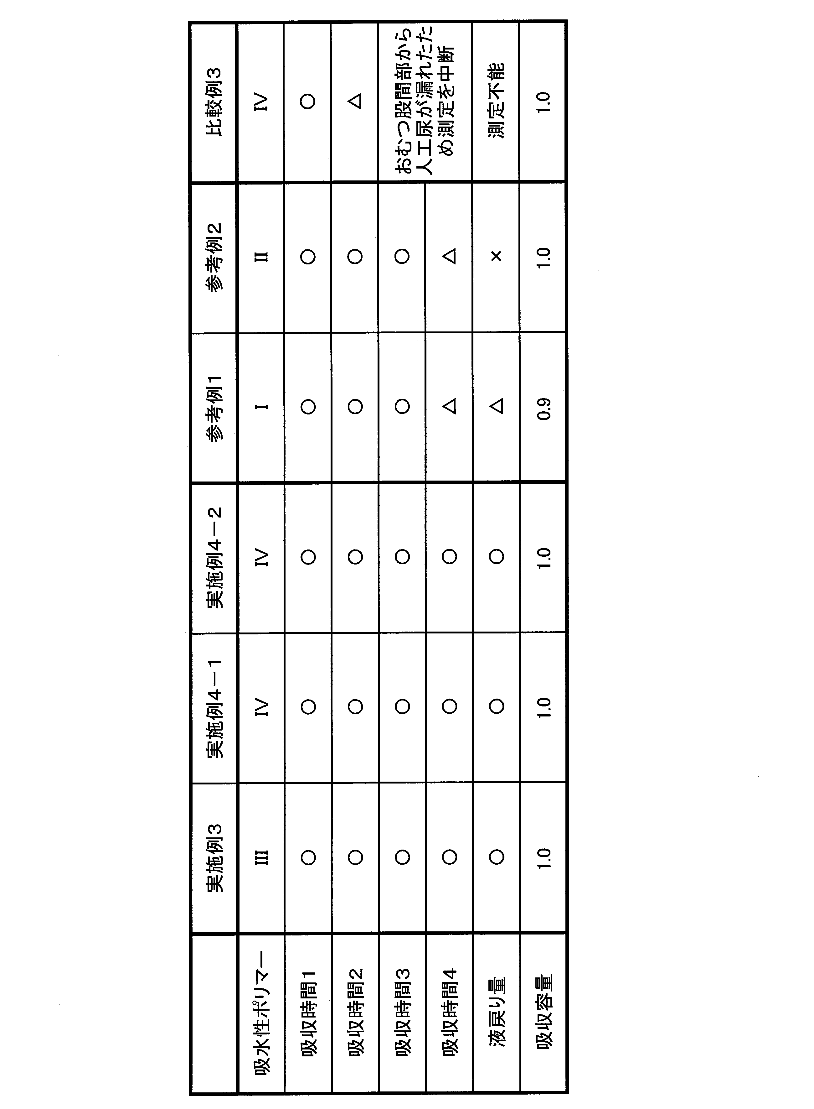


実施例3,4-1,4-2では、いずれも1回目から4回目の液体の吸収時間は30秒未満であった。一方、参考例1,2では、1回目から3回目の吸収時間に関しては実施例3,4-1,4-2とほぼ同等の評価結果であったが、4回目の吸収時間は60秒未満であった。溝(凹部)を有していない吸収体を用いた比較例Cにおいては、3回目の測定中に試験液がおむつの股間に相当する部分から漏れ、測定を継続することができなかった。この結果、実施例の液体の吸収性能が使用開始から繰り返し吸収末期まで高く維持されることがわかった。
このように、本発明の吸収体10に用いる吸水性ポリマー42は、例えば、乳児の尿が1回あたり40cc程度であるとして、1回目の排せつ(排尿)、2回目、3回目、4回目の排せつであっても、吸水性ポリマー42が排せつ液(尿)を吸収しても膨潤しにくく、荷重によって潰れにくいので、1回目の排せつ時の溝20の状態を保持している。このため、吸水性ポリマー42によって溝20が閉塞されることはなく、溝20の通液性が確保される。その結果、排せつ液の吸収速度が速くなる。
また、実施例3,4-1,4-2では液戻り量が1.0g未満であり、吸水量が少ない吸水性ポリマーを用いた参考例1、加圧下吸収量が低い吸水性ポリマーを用いた参考例2では液戻り量が1.0g以上で、溝(凹部)を有していない吸収体を用いた比較例3では、前述の様に測定不能であった。
参考例2のように加圧下における吸収量が低い従来の吸水性ポリマーでは、1回目~3回目の排尿では溝20の通液が可能である。しかし、4回目における排尿では、3回目までの排尿で膨潤した吸水性ポリマーに着用者の荷重がかかることによって、吸水性ポリマーがつぶされ、溝20内にはみ出して、最悪の場合、溝20を塞いでしまうため、溝20を通しての通液が困難になる。このため、4回目の排せつでは、溝20内を排せつ液が流れにくくなるので、液の拡散が十分にできなくなり、液戻り量が多くなる。
一方、実施例3,4-1,4-2で用いた吸収体ポリマーでは、吸水性ポリマーが排せつ液(尿)を繰り返し吸収しても、膨潤しにくく荷重によって潰れにくいので、溝20を塞ぐこともなく、吸収体全体に排せつ液を拡散させ、吸収させることができるので、液戻り量を1.0g未満にすることができる。
さらに、実施例3,4-1,4-2の吸収容量は、吸水性ポリマーの使用量が実施例4-1よりも1.1倍多い比較例3に対して、いずれも1.0であり、比較例3と同等の吸収容量であることがわかった。すなわち、実施例3,4-1,4-2は十分な吸収容量を有することがわかった。
以上説明したように、本発明の吸収体10およびその吸収体10を用いた吸収性物品50によれば、長時間使用により繰り返しの排せつ液の吸収において、高吸収量と高吸収速度とを両立し、液戻り量が少なく、高い吸収性能を発揮することができる。
このように、本発明の吸収体10に用いる吸水性ポリマー42は、例えば、乳児の尿が1回あたり40cc程度であるとして、1回目の排せつ(排尿)、2回目、3回目、4回目の排せつであっても、吸水性ポリマー42が排せつ液(尿)を吸収しても膨潤しにくく、荷重によって潰れにくいので、1回目の排せつ時の溝20の状態を保持している。このため、吸水性ポリマー42によって溝20が閉塞されることはなく、溝20の通液性が確保される。その結果、排せつ液の吸収速度が速くなる。
また、実施例3,4-1,4-2では液戻り量が1.0g未満であり、吸水量が少ない吸水性ポリマーを用いた参考例1、加圧下吸収量が低い吸水性ポリマーを用いた参考例2では液戻り量が1.0g以上で、溝(凹部)を有していない吸収体を用いた比較例3では、前述の様に測定不能であった。
参考例2のように加圧下における吸収量が低い従来の吸水性ポリマーでは、1回目~3回目の排尿では溝20の通液が可能である。しかし、4回目における排尿では、3回目までの排尿で膨潤した吸水性ポリマーに着用者の荷重がかかることによって、吸水性ポリマーがつぶされ、溝20内にはみ出して、最悪の場合、溝20を塞いでしまうため、溝20を通しての通液が困難になる。このため、4回目の排せつでは、溝20内を排せつ液が流れにくくなるので、液の拡散が十分にできなくなり、液戻り量が多くなる。
一方、実施例3,4-1,4-2で用いた吸収体ポリマーでは、吸水性ポリマーが排せつ液(尿)を繰り返し吸収しても、膨潤しにくく荷重によって潰れにくいので、溝20を塞ぐこともなく、吸収体全体に排せつ液を拡散させ、吸収させることができるので、液戻り量を1.0g未満にすることができる。
さらに、実施例3,4-1,4-2の吸収容量は、吸水性ポリマーの使用量が実施例4-1よりも1.1倍多い比較例3に対して、いずれも1.0であり、比較例3と同等の吸収容量であることがわかった。すなわち、実施例3,4-1,4-2は十分な吸収容量を有することがわかった。
以上説明したように、本発明の吸収体10およびその吸収体10を用いた吸収性物品50によれば、長時間使用により繰り返しの排せつ液の吸収において、高吸収量と高吸収速度とを両立し、液戻り量が少なく、高い吸収性能を発揮することができる。
実施例5ないし6では、いずれも1回目は液体の吸収時間が30秒未満であり、2回目から4回目の吸収でも吸収時間が60秒未満であった。一方、比較例においては、比較例3は、吸収時間に関しては実施例とほぼ同等の評価結果が得られたが、加圧下吸収量が低い吸水性ポリマーを用いた参考例4、および溝を有していない吸収体を用いた比較例4、5では2回目以降の吸収時間が60秒以上かかり、吸収時間が長くなった。この結果、実施例の液体の吸収性能が使用開始から繰り返し吸収末期まで高く維持されることがわかった。
このように、本発明の吸収体10に用いる吸水性ポリマー42は、例えば、乳児の尿が1回あたり40cc程度であるとして、1回目の排せつ(排尿)、2回目、3回目、4回目の排せつであっても、吸水性ポリマー42が排せつ液(尿)を吸収しても膨潤しにくいので、1回目の排せつ時の溝20の状態を保持している。このため、吸水性ポリマー42によって溝20が閉塞されることはなく、溝20の通液性が確保される。その結果、排せつ液の吸収速度が速くなる。
また、実施例3ないし4では液戻り量が1.5g未満であり、吸水量が少ない吸水性ポリマーを用いた参考例3、加圧下吸収量が低い吸水性ポリマーを用いた参考例4、および吸収体に溝を有さない比較例4では液戻り量が1.5g以上であった。この結果、各実施例の液戻り量が少ないことがわかった。
このように、参考例4のように加圧下における吸収量が低い従来の吸水性ポリマーでは、1回目の排尿では溝20の通液が可能である。しかし、2回目以降の排尿では、1回目の排尿で膨潤した吸水性ポリマーに着用者の荷重がかかることによって、吸水性ポリマーがつぶされ、溝20内にはみ出して、最悪の場合、溝20を塞いでしまうため、溝20を通しての通液が困難になる。このため、2回目以降の排せつでは、溝20内を排せつ液が流れにくくなる、もしくは流れなくなるので、液の拡散が十分にできなくなり、液戻り量が多くなる。
一方、各実施例で用いた吸収体ポリマーでは2回目以降の排せつに対しても吸水性ポリマーが膨潤することがほとんどないので、溝20を塞ぐこともなく、吸収体全体に排せつ液を拡散させ、吸収させることができるので、液戻り量を1.5g未満にすることができる。
一方、各実施例で用いた吸収体ポリマーでは2回目以降の排せつに対しても吸水性ポリマーが膨潤することがほとんどないので、溝20を塞ぐこともなく、吸収体全体に排せつ液を拡散させ、吸収させることができるので、液戻り量を1.5g未満にすることができる。
さらに、実施例5ないし6の吸収容量は、吸水性ポリマーの使用量が実施例5よりも1.13倍多い比較例5に対して、いずれも1.0であり、比較例5と同等の吸収容量であることがわかった。すなわち、各実施例は十分な吸収容量を有することがわかった。
このように、各実施例が十分な吸収容量を有することから、各実施例においては、液戻り量が1.0g未満と少なくなっており、一方、参考例3では、吸収容量が0.8と低くなっているので、液戻り量が多くなる。また、比較例4では、実施例5と同じ吸水性ポリマーIIIを同量用いているが、溝を有していないため、吸収体としての吸収容量も0.8と低くなり、液戻り量が多くなる。
このように、各実施例が十分な吸収容量を有することから、各実施例においては、液戻り量が1.0g未満と少なくなっており、一方、参考例3では、吸収容量が0.8と低くなっているので、液戻り量が多くなる。また、比較例4では、実施例5と同じ吸水性ポリマーIIIを同量用いているが、溝を有していないため、吸収体としての吸収容量も0.8と低くなり、液戻り量が多くなる。
以上説明したように、本発明の吸収体10およびその吸収体10を用いた吸収性物品50によれば、長時間使用により繰り返しの排せつ液の吸収において、高吸収量と高吸収速度とを両立し、液戻り量が少なく、高い吸収性能を発揮することができる。
本発明の吸収体10は、上記の実施形態に制限されるものではなく、上述のような展開型おむつのほか、パンツ型おむつ、生理用ショーツ、ショーツ型ナプキン、生理用ナプキン、失禁パッド、失禁ライナ等の吸収性物品に含まれる吸収体に用いることができる。また、上記吸収性物品が乳幼児用のものであっても、成人用のものであっても適用することができる。さらに、尿に限らずその他、経血、オリモノ、軟便等に対しても効果的である。
本発明をその実施態様とともに説明したが、我々は特に指定しない限り我々の発明を説明のどの細部においても限定しようとするものではなく、添付の請求の範囲に示した発明の精神と範囲に反することなく幅広く解釈されるべきであると考える。
本願は、2010年12月24日に日本国で特許出願された特願2010‐287970、2010年12月24日に日本国で特許出願された特願2010‐287971、2010年12月24日に日本国で特許出願された特願2010‐287972、2011年8月30日に日本国で特許出願された特願2011-186764、及び2011年8月30日に日本国で特許出願された特願2011-186765に基づく優先権を主張するものであり、これらはここに参照してその内容を本明細書の記載の一部として取り込む。
10 吸収体
11 第1吸収部
12 第2吸収部
13 第3吸収部
20 凹部(溝)
21 第1凹部
22 第2凹部
23 第3凹部
31 受液層部
32 突出液吸収貯蔵部
16 表面シート
17 裏面シート
19 中間シート
41 パルプ
42 吸水性ポリマー
44 吸収体ブロック
50 吸収性物品(おむつ)
L 長手方向
d 幅方向
S2,S3 周面
11 第1吸収部
12 第2吸収部
13 第3吸収部
20 凹部(溝)
21 第1凹部
22 第2凹部
23 第3凹部
31 受液層部
32 突出液吸収貯蔵部
16 表面シート
17 裏面シート
19 中間シート
41 パルプ
42 吸水性ポリマー
44 吸収体ブロック
50 吸収性物品(おむつ)
L 長手方向
d 幅方向
S2,S3 周面
Claims (20)
- 吸収体を長手方向に3区分した中間部の第1吸収部と、前記第1吸収部の一方側に区分された第2吸収部と、前記第1吸収部の他方側に区分された第3吸収部とを有し、
前記各吸収部は、液体を吸収して平面方向に拡散する受液層部と、該受液層部の一面側に該受液層部に連続して複数に分立して配され液体を吸収して貯える突出液吸収貯蔵部とを有し、かつ、一方の面にまたは両方の面の対向する位置に溝状に窪んだ凹部を有し、前記突出液吸収貯蔵部間に前記凹部が配され、
前記第1吸収部に配される第1凹部は平面視した前記第1吸収部の外縁より内側にあって前記長手方向に配され、
前記第2、第3吸収部のそれぞれに配される第2、第3凹部はそれぞれ前記長手方向に対して斜め方向に配され、
前記第1、第2凹部同士および前記第1、第3凹部同士が連続した凹部に構成されているかまたは前記第1凹部と前記第2凹部および前記第3凹部とが離間されていて、
前記突出液吸収貯蔵部は前記凹部よりも面積率が高く、
前記凹部底部の前記受液層部は前記突出液吸収貯蔵部より坪量および密度が低い
吸収体。 - 前記突出液吸収貯蔵部はその下部の前記受液層部よりも密度が高い
請求項1記載の吸収体。 - 前記突出液吸収貯蔵部の側面は前記突出液吸収貯蔵部の中央部より密度が低い
請求項1または請求項2に記載の吸収体。 - 前記凹部の底部に前記吸収体の一部があり、前記凹部の底部にある前記吸収体の密度が、該凹部の底部以外の前記吸収体の密度より低い請求項1ないし請求項3のいずれか1項に記載の吸収体。
- 吸収体を長手方向に3区分した中間部の第1吸収部と、前記第1吸収部の一方側に区分された第2吸収部と、前記第1吸収部の他方側に区分された第3吸収部とを有し、
前記各吸収部は、液体を吸収して平面方向に拡散する受液層部と、該受液層部の一面側に該受液層部に連続して複数に分立して配され液体を吸収して貯える突出液吸収貯蔵部とを有し、かつ、一方の面にまたは両方の面の対向する位置に溝状に窪んだ凹部を有し、前記突出液吸収貯蔵部間に前記凹部が配され、
前記突出液吸収貯蔵部は前記凹部よりも面積率が高く、
前記凹部底部の前記受液層部は前記突出液吸収貯蔵部より坪量および密度が低い吸収体であって、
前記吸収体はパルプと吸水性ポリマーとを有する吸収体であり、前記凹部は該吸収体の厚みの20%以上100%未満の深さを有し、
前記吸収体における[パルプの質量]/[吸水性ポリマーの質量]で表される質量比が1/3以上1/0.01以下であり、
前記吸水性ポリマーは、吸水量が30g/g以上50g/g以下であり、2kPaの加圧下における液体の吸収量が20g/g以上40g/g以下である吸収体。 - 前記吸水性ポリマーは、吸水量が30g/g以上45g/g以下である請求項5記載の吸収体。
- 前記吸水性ポリマーは、2kPaの加圧下における液体の吸収量が20g/g以上35g/g以下である請求項5または請求項6記載の吸収体。
- 前記凹部は、平面視した前記吸収体の面積に対して平面視した前記凹部の総面積が10%以上40%以下となる請求項1ないし請求項7のいずれか1項に記載の吸収体。
- 前記吸収体の厚みは0.5mm以上20mm以下である請求項1ないし請求項8のいずれか1項に記載の吸収体。
- 前記凹部の幅は1mm以上10mm以下である請求項1ないし請求項9のいずれか1項に記載の吸収体。
- 前記第2凹部は平面視した前記第2吸収部の外縁より内側にあり、前記第3凹部は平面視した前記第3吸収部の外縁より内側にある
請求項1ないし請求項10のいずれか1項に記載の吸収体。 - 前記第1、第2、第3凹部は、それぞれの底部に前記吸収体の一部を有する
請求項1ないし請求項11のいずれか1項に記載の吸収体。 - 前記第2凹部のうちの複数本の凹部は、前記第1凹部が配される領域内でつながっており、
前記第3凹部のうちの複数本の凹部は、前記第1凹部が配される領域内でつながっている
請求項1ないし請求項12のいずれか1項に記載の吸収体。 - 前記第1凹部は複数配され、前記長手方向と交差する方向に前記第1凹部同士をつなぐ連絡凹部が配された
請求項1ないし請求項13のいずれか1項に記載の吸収体。 - 前記第2、第3凹部のそれぞれの底部の前記吸収体の坪量は、前記第1凹部の底部の前記吸収体の坪量よりも大きい
請求項1ないし請求項14のいずれか1項に記載の吸収体。 - 前記請求項1ないし請求項15のいずれか1項に記載の吸収体を有する吸収性物品。
- 前記吸収体は前記受液層部を非肌当接面側に配する請求項16に記載の吸収性物品。
- 肌当接面側を配置される液透過性の表面シートと、
非肌当接面側を配置される液不透過性の裏面シートと、
前記両シートに介在配置された吸収体とを備えた請求項16または請求項17に記載の吸収性物品。 - 前記吸収体の前記表面シート側に凹部が存在する請求項18記載の吸収性物品。
- 前記吸収体の前記裏面シート側に凹部が存在する請求項18記載の吸収性物品。
Priority Applications (2)
| Application Number | Priority Date | Filing Date | Title |
|---|---|---|---|
| CN201180060691.9A CN103260570B (zh) | 2010-12-24 | 2011-08-30 | 吸收体及吸收性物品 |
| RU2013134459/12A RU2560916C2 (ru) | 2010-12-24 | 2011-08-30 | Впитывающий элемент и впитывающее изделие |
Applications Claiming Priority (10)
| Application Number | Priority Date | Filing Date | Title |
|---|---|---|---|
| JP2010-287972 | 2010-12-24 | ||
| JP2010287970 | 2010-12-24 | ||
| JP2010287971 | 2010-12-24 | ||
| JP2010-287971 | 2010-12-24 | ||
| JP2010-287970 | 2010-12-24 | ||
| JP2010287972 | 2010-12-24 | ||
| JP2011186765A JP5889577B2 (ja) | 2010-12-24 | 2011-08-30 | 吸収体および吸収性物品 |
| JP2011-186765 | 2011-08-30 | ||
| JP2011-186764 | 2011-08-30 | ||
| JP2011186764A JP2012143534A (ja) | 2010-12-24 | 2011-08-30 | 吸収体および吸収性物品 |
Publications (1)
| Publication Number | Publication Date |
|---|---|
| WO2012086265A1 true WO2012086265A1 (ja) | 2012-06-28 |
Family
ID=46313550
Family Applications (1)
| Application Number | Title | Priority Date | Filing Date |
|---|---|---|---|
| PCT/JP2011/069663 Ceased WO2012086265A1 (ja) | 2010-12-24 | 2011-08-30 | 吸収体および吸収性物品 |
Country Status (1)
| Country | Link |
|---|---|
| WO (1) | WO2012086265A1 (ja) |
Cited By (13)
| Publication number | Priority date | Publication date | Assignee | Title |
|---|---|---|---|---|
| JP2012245236A (ja) * | 2011-05-30 | 2012-12-13 | Daio Paper Corp | 吸収性物品 |
| JP2013085561A (ja) * | 2011-10-13 | 2013-05-13 | Kao Corp | 吸収体 |
| JP2014104036A (ja) * | 2012-11-26 | 2014-06-09 | Kao Corp | 吸収性物品 |
| CN105338937A (zh) * | 2013-06-28 | 2016-02-17 | 大王制纸株式会社 | 吸收性物品 |
| EP3001992A1 (en) * | 2014-09-30 | 2016-04-06 | Johnson & Johnson Consumer Inc. | Absorbent article demonstrating controlled deformation and longitudinal fluid distribution |
| EP3001997A1 (en) * | 2014-09-30 | 2016-04-06 | Johnson & Johnson Consumer Inc. | Absorbent article demonstrating controlled deformation and longitudinal fluid distribution |
| EP3001993A1 (en) * | 2014-09-30 | 2016-04-06 | Johnson & Johnson Consumer Inc. | Absorbent article demonstrating controlled deformation and longitudinal fluid distribution |
| CN105455970A (zh) * | 2014-09-30 | 2016-04-06 | 强生消费者公司 | 显示出受控变形和纵向流体分布的吸收制品 |
| EP3001994A1 (en) * | 2014-09-30 | 2016-04-06 | Johnson & Johnson Consumer Inc. | Absorbent article demonstrating controlled deformation and longitudinal fluid distribution |
| EP3001996A1 (en) * | 2014-09-30 | 2016-04-06 | Johnson & Johnson Consumer Inc. | Absorbent article demonstrating controlled deformation and longitudinal fluid distribution |
| JP2017074281A (ja) * | 2015-10-16 | 2017-04-20 | 花王株式会社 | 吸収性物品 |
| WO2019138842A1 (ja) * | 2018-01-10 | 2019-07-18 | ユニ・チャーム株式会社 | 吸収性物品 |
| CN114845679A (zh) * | 2019-12-23 | 2022-08-02 | 花王株式会社 | 吸收体和吸收性物品 |
Citations (7)
| Publication number | Priority date | Publication date | Assignee | Title |
|---|---|---|---|---|
| JP2006141615A (ja) * | 2004-11-18 | 2006-06-08 | Uni Charm Corp | 吸液性芯材成型ドラム |
| JP2008125716A (ja) * | 2006-11-20 | 2008-06-05 | San-Dia Polymer Ltd | 吸収性樹脂粒子、これを用いてなる吸収体及び吸収性物品 |
| JP2008237384A (ja) * | 2007-03-26 | 2008-10-09 | Uni Charm Corp | 吸収性物品 |
| JP2008237382A (ja) * | 2007-03-26 | 2008-10-09 | Uni Charm Corp | 吸収性物品、及び、吸収性物品の製造方法 |
| JP2009297048A (ja) * | 2008-06-10 | 2009-12-24 | Kao Corp | 吸収性物品 |
| JP2010068989A (ja) * | 2008-09-18 | 2010-04-02 | Daio Paper Corp | 使い捨て吸収性物品 |
| JP2010233839A (ja) * | 2009-03-31 | 2010-10-21 | Uni Charm Corp | 吸収性物品及び吸収性物品の製造方法 |
-
2011
- 2011-08-30 WO PCT/JP2011/069663 patent/WO2012086265A1/ja not_active Ceased
Patent Citations (7)
| Publication number | Priority date | Publication date | Assignee | Title |
|---|---|---|---|---|
| JP2006141615A (ja) * | 2004-11-18 | 2006-06-08 | Uni Charm Corp | 吸液性芯材成型ドラム |
| JP2008125716A (ja) * | 2006-11-20 | 2008-06-05 | San-Dia Polymer Ltd | 吸収性樹脂粒子、これを用いてなる吸収体及び吸収性物品 |
| JP2008237384A (ja) * | 2007-03-26 | 2008-10-09 | Uni Charm Corp | 吸収性物品 |
| JP2008237382A (ja) * | 2007-03-26 | 2008-10-09 | Uni Charm Corp | 吸収性物品、及び、吸収性物品の製造方法 |
| JP2009297048A (ja) * | 2008-06-10 | 2009-12-24 | Kao Corp | 吸収性物品 |
| JP2010068989A (ja) * | 2008-09-18 | 2010-04-02 | Daio Paper Corp | 使い捨て吸収性物品 |
| JP2010233839A (ja) * | 2009-03-31 | 2010-10-21 | Uni Charm Corp | 吸収性物品及び吸収性物品の製造方法 |
Cited By (41)
| Publication number | Priority date | Publication date | Assignee | Title |
|---|---|---|---|---|
| JP2012245236A (ja) * | 2011-05-30 | 2012-12-13 | Daio Paper Corp | 吸収性物品 |
| JP2013085561A (ja) * | 2011-10-13 | 2013-05-13 | Kao Corp | 吸収体 |
| JP2014104036A (ja) * | 2012-11-26 | 2014-06-09 | Kao Corp | 吸収性物品 |
| CN105338937A (zh) * | 2013-06-28 | 2016-02-17 | 大王制纸株式会社 | 吸收性物品 |
| CN105338937B (zh) * | 2013-06-28 | 2019-05-14 | 大王制纸株式会社 | 吸收性物品 |
| US10285873B2 (en) | 2014-09-30 | 2019-05-14 | Johnson & Johnson Consumer Inc. | Absorbent article demonstrating controlled deformation and longitudinal fluid distribution |
| US10307308B2 (en) | 2014-09-30 | 2019-06-04 | Johnson & Johnson Consumer Inc. | Absorbent article demonstrating controlled deformation and longitudinal fluid distribution |
| EP3001993A1 (en) * | 2014-09-30 | 2016-04-06 | Johnson & Johnson Consumer Inc. | Absorbent article demonstrating controlled deformation and longitudinal fluid distribution |
| CN105455970A (zh) * | 2014-09-30 | 2016-04-06 | 强生消费者公司 | 显示出受控变形和纵向流体分布的吸收制品 |
| EP3001994A1 (en) * | 2014-09-30 | 2016-04-06 | Johnson & Johnson Consumer Inc. | Absorbent article demonstrating controlled deformation and longitudinal fluid distribution |
| EP3001996A1 (en) * | 2014-09-30 | 2016-04-06 | Johnson & Johnson Consumer Inc. | Absorbent article demonstrating controlled deformation and longitudinal fluid distribution |
| CN105455969A (zh) * | 2014-09-30 | 2016-04-06 | 强生消费者公司 | 显示出受控变形和纵向流体分布的吸收制品 |
| CN105455957A (zh) * | 2014-09-30 | 2016-04-06 | 强生消费者公司 | 显示出受控变形和纵向流体分布的吸收制品 |
| EP3001995A1 (en) * | 2014-09-30 | 2016-04-06 | Johnson & Johnson Consumer Inc. | Absorbent article demonstrating controlled deformation and longitudinal fluid distribution |
| CN105455959A (zh) * | 2014-09-30 | 2016-04-06 | 强生消费者公司 | 显示出受控变形和纵向流体分布的吸收制品 |
| CN105455971A (zh) * | 2014-09-30 | 2016-04-06 | 强生消费者公司 | 显示出受控变形和纵向流体分布的吸收制品 |
| EP3711728A1 (en) * | 2014-09-30 | 2020-09-23 | Johnson & Johnson Consumer Inc. | Absorbent article demonstrating controlled deformation and longitudinal fluid distribution |
| US9968496B2 (en) | 2014-09-30 | 2018-05-15 | Johnson & Johnson Consumer Inc. | Absorbent article demonstrating controlled deformation and longitudinal fluid distribution |
| US9999554B2 (en) | 2014-09-30 | 2018-06-19 | Johnson & Johnson Consumer Inc. | Absorbent article demonstrating controlled deformation and longitudinal fluid distribution |
| US10265224B2 (en) | 2014-09-30 | 2019-04-23 | Johnson & Johnson Consumer Inc. | Absorbent article demonstrating controlled deformation and longitudinal fluid distribution |
| EP3001997A1 (en) * | 2014-09-30 | 2016-04-06 | Johnson & Johnson Consumer Inc. | Absorbent article demonstrating controlled deformation and longitudinal fluid distribution |
| EP3001992A1 (en) * | 2014-09-30 | 2016-04-06 | Johnson & Johnson Consumer Inc. | Absorbent article demonstrating controlled deformation and longitudinal fluid distribution |
| CN105455958A (zh) * | 2014-09-30 | 2016-04-06 | 强生消费者公司 | 显示出受控变形和纵向流体分布的吸收制品 |
| EP3494941A1 (en) * | 2014-09-30 | 2019-06-12 | Johnson & Johnson Consumer Inc. | Absorbent article demonstrating controlled deformation and longitudinal fluid distribution |
| EP3510982A1 (en) * | 2014-09-30 | 2019-07-17 | Johnson & Johnson Consumer Inc. | Absorbent article demonstrating controlled deformation and longitudinal fluid distribution |
| CN105455971B (zh) * | 2014-09-30 | 2020-08-14 | 强生消费者公司 | 显示出受控变形和纵向流体分布的吸收制品 |
| RU2703118C2 (ru) * | 2014-09-30 | 2019-10-15 | Джонсон энд Джонсон Консьюмер Инк. | Абсорбирующее изделие, демонстрирующее управляемую деформацию и продольное распределение текучей среды |
| AU2015224433B2 (en) * | 2014-09-30 | 2020-01-16 | Kenvue Brands Llc | Absorbent article demonstrating controlled deformation and longitudinal fluid distribution |
| AU2015224438B2 (en) * | 2014-09-30 | 2020-02-06 | Kenvue Brands Llc | Absorbent article demonstrating controlled deformation and longitudinal fluid distribution |
| AU2015224442B2 (en) * | 2014-09-30 | 2020-02-06 | Kenvue Brands Llc | Absorbent article demonstrating controlled deformation and longitudinal fluid distribution |
| RU2719209C2 (ru) * | 2014-09-30 | 2020-04-17 | Джонсон энд Джонсон Консьюмер Инк. | Абсорбирующее изделие, демонстрирующее управляемую деформацию и продольное распределение жидкости |
| AU2015224434B2 (en) * | 2014-09-30 | 2020-06-18 | Kenvue Brands Llc | Absorbent article demonstrating controlled deformation and longitudinal fluid distribution |
| CN105455958B (zh) * | 2014-09-30 | 2020-06-26 | 强生消费者公司 | 显示出受控变形和纵向流体分布的吸收制品 |
| CN105455969B (zh) * | 2014-09-30 | 2020-08-14 | 强生消费者公司 | 显示出受控变形和纵向流体分布的吸收制品 |
| CN105455959B (zh) * | 2014-09-30 | 2020-08-14 | 强生消费者公司 | 显示出受控变形和纵向流体分布的吸收制品 |
| CN105455970B (zh) * | 2014-09-30 | 2020-08-14 | 强生消费者公司 | 显示出受控变形和纵向流体分布的吸收制品 |
| CN105455957B (zh) * | 2014-09-30 | 2020-08-14 | 强生消费者公司 | 显示出受控变形和纵向流体分布的吸收制品 |
| JP2017074281A (ja) * | 2015-10-16 | 2017-04-20 | 花王株式会社 | 吸収性物品 |
| WO2019138842A1 (ja) * | 2018-01-10 | 2019-07-18 | ユニ・チャーム株式会社 | 吸収性物品 |
| US11969327B2 (en) | 2018-01-10 | 2024-04-30 | Unicharm Corporation | Absorbent article |
| CN114845679A (zh) * | 2019-12-23 | 2022-08-02 | 花王株式会社 | 吸收体和吸收性物品 |
Similar Documents
| Publication | Publication Date | Title |
|---|---|---|
| RU2560916C2 (ru) | Впитывающий элемент и впитывающее изделие | |
| JP6515245B2 (ja) | 吸収体および吸収性物品 | |
| CN101873843B (zh) | 吸收性物品 | |
| JP6189143B2 (ja) | 吸収性物品 | |
| RU2552905C2 (ru) | Одноразовое абсорбирующее изделие | |
| JP5417133B2 (ja) | 吸収性物品 | |
| CN104244889B (zh) | 吸收体及使用其的吸收性物品 | |
| US10555843B2 (en) | Absorbent article | |
| EP3272322B1 (en) | Absorbent article | |
| JP5912472B2 (ja) | 吸収体 | |
| US20190053958A1 (en) | Absorbent article | |
| CN110022824B (zh) | 吸收性物品 | |
| KR20160102423A (ko) | 흡수성 물품의 제조 방법 | |
| US10806637B2 (en) | Absorbent article | |
| WO2016148192A1 (ja) | 吸収性物品 | |
| JP2010088528A (ja) | 吸収性物品 | |
| JP2011000231A (ja) | 吸収体及び吸収性物品 | |
| JP6192794B1 (ja) | 吸収性物品 | |
| CN1678262A (zh) | 包括含有用磷酸酯或硫酸酯处理过的热塑性纤维的气流成网混合物材料的吸收制品 | |
| JP2015188624A (ja) | 吸収性物品 | |
| JP5878431B2 (ja) | 吸収体および吸収性物品 | |
| JP6033612B2 (ja) | 吸収体及びこれを用いた吸収性物品 | |
| JP2018094246A (ja) | 吸収体 | |
| JP6351792B2 (ja) | 吸収性物品 | |
| JP2022117155A (ja) | 吸収性物品 |
Legal Events
| Date | Code | Title | Description |
|---|---|---|---|
| 121 | Ep: the epo has been informed by wipo that ep was designated in this application |
Ref document number: 11850440 Country of ref document: EP Kind code of ref document: A1 |
|
| NENP | Non-entry into the national phase |
Ref country code: DE |
|
| ENP | Entry into the national phase |
Ref document number: 2013134459 Country of ref document: RU Kind code of ref document: A |
|
| 122 | Ep: pct application non-entry in european phase |
Ref document number: 11850440 Country of ref document: EP Kind code of ref document: A1 |