WO2012086078A1 - 内燃機関の制御装置 - Google Patents
内燃機関の制御装置 Download PDFInfo
- Publication number
- WO2012086078A1 WO2012086078A1 PCT/JP2010/073424 JP2010073424W WO2012086078A1 WO 2012086078 A1 WO2012086078 A1 WO 2012086078A1 JP 2010073424 W JP2010073424 W JP 2010073424W WO 2012086078 A1 WO2012086078 A1 WO 2012086078A1
- Authority
- WO
- WIPO (PCT)
- Prior art keywords
- fuel ratio
- air
- exhaust
- purification catalyst
- deterioration
- Prior art date
- Legal status (The legal status is an assumption and is not a legal conclusion. Google has not performed a legal analysis and makes no representation as to the accuracy of the status listed.)
- Ceased
Links
Images





Classifications
-
- F—MECHANICAL ENGINEERING; LIGHTING; HEATING; WEAPONS; BLASTING
- F02—COMBUSTION ENGINES; HOT-GAS OR COMBUSTION-PRODUCT ENGINE PLANTS
- F02B—INTERNAL-COMBUSTION PISTON ENGINES; COMBUSTION ENGINES IN GENERAL
- F02B37/00—Engines characterised by provision of pumps driven at least for part of the time by exhaust
-
- F—MECHANICAL ENGINEERING; LIGHTING; HEATING; WEAPONS; BLASTING
- F01—MACHINES OR ENGINES IN GENERAL; ENGINE PLANTS IN GENERAL; STEAM ENGINES
- F01N—GAS-FLOW SILENCERS OR EXHAUST APPARATUS FOR MACHINES OR ENGINES IN GENERAL; GAS-FLOW SILENCERS OR EXHAUST APPARATUS FOR INTERNAL-COMBUSTION ENGINES
- F01N3/00—Exhaust or silencing apparatus having means for purifying, rendering innocuous, or otherwise treating exhaust
- F01N3/08—Exhaust or silencing apparatus having means for purifying, rendering innocuous, or otherwise treating exhaust for rendering innocuous
- F01N3/0807—Exhaust or silencing apparatus having means for purifying, rendering innocuous, or otherwise treating exhaust for rendering innocuous by using absorbents or adsorbents
- F01N3/0828—Exhaust or silencing apparatus having means for purifying, rendering innocuous, or otherwise treating exhaust for rendering innocuous by using absorbents or adsorbents characterised by the absorbed or adsorbed substances
- F01N3/0864—Oxygen
-
- F—MECHANICAL ENGINEERING; LIGHTING; HEATING; WEAPONS; BLASTING
- F02—COMBUSTION ENGINES; HOT-GAS OR COMBUSTION-PRODUCT ENGINE PLANTS
- F02B—INTERNAL-COMBUSTION PISTON ENGINES; COMBUSTION ENGINES IN GENERAL
- F02B37/00—Engines characterised by provision of pumps driven at least for part of the time by exhaust
- F02B37/12—Control of the pumps
- F02B37/18—Control of the pumps by bypassing exhaust from the inlet to the outlet of turbine or to the atmosphere
-
- F—MECHANICAL ENGINEERING; LIGHTING; HEATING; WEAPONS; BLASTING
- F02—COMBUSTION ENGINES; HOT-GAS OR COMBUSTION-PRODUCT ENGINE PLANTS
- F02B—INTERNAL-COMBUSTION PISTON ENGINES; COMBUSTION ENGINES IN GENERAL
- F02B39/00—Component parts, details, or accessories relating to, driven charging or scavenging pumps, not provided for in groups F02B33/00 - F02B37/00
- F02B39/02—Drives of pumps; Varying pump drive gear ratio
- F02B39/08—Non-mechanical drives, e.g. fluid drives having variable gear ratio
- F02B39/10—Non-mechanical drives, e.g. fluid drives having variable gear ratio electric
-
- F—MECHANICAL ENGINEERING; LIGHTING; HEATING; WEAPONS; BLASTING
- F02—COMBUSTION ENGINES; HOT-GAS OR COMBUSTION-PRODUCT ENGINE PLANTS
- F02D—CONTROLLING COMBUSTION ENGINES
- F02D41/00—Electrical control of supply of combustible mixture or its constituents
- F02D41/0002—Controlling intake air
- F02D41/0007—Controlling intake air for control of turbo-charged or super-charged engines
-
- F—MECHANICAL ENGINEERING; LIGHTING; HEATING; WEAPONS; BLASTING
- F02—COMBUSTION ENGINES; HOT-GAS OR COMBUSTION-PRODUCT ENGINE PLANTS
- F02D—CONTROLLING COMBUSTION ENGINES
- F02D41/00—Electrical control of supply of combustible mixture or its constituents
- F02D41/02—Circuit arrangements for generating control signals
- F02D41/021—Introducing corrections for particular conditions exterior to the engine
- F02D41/0235—Introducing corrections for particular conditions exterior to the engine in relation with the state of the exhaust gas treating apparatus
-
- F—MECHANICAL ENGINEERING; LIGHTING; HEATING; WEAPONS; BLASTING
- F02—COMBUSTION ENGINES; HOT-GAS OR COMBUSTION-PRODUCT ENGINE PLANTS
- F02D—CONTROLLING COMBUSTION ENGINES
- F02D41/00—Electrical control of supply of combustible mixture or its constituents
- F02D41/02—Circuit arrangements for generating control signals
- F02D41/14—Introducing closed-loop corrections
- F02D41/1438—Introducing closed-loop corrections using means for determining characteristics of the combustion gases; Sensors therefor
- F02D41/1444—Introducing closed-loop corrections using means for determining characteristics of the combustion gases; Sensors therefor characterised by the characteristics of the combustion gases
- F02D41/1454—Introducing closed-loop corrections using means for determining characteristics of the combustion gases; Sensors therefor characterised by the characteristics of the combustion gases the characteristics being an oxygen content or concentration or the air-fuel ratio
- F02D41/1456—Introducing closed-loop corrections using means for determining characteristics of the combustion gases; Sensors therefor characterised by the characteristics of the combustion gases the characteristics being an oxygen content or concentration or the air-fuel ratio with sensor output signal being linear or quasi-linear with the concentration of oxygen
-
- F—MECHANICAL ENGINEERING; LIGHTING; HEATING; WEAPONS; BLASTING
- F01—MACHINES OR ENGINES IN GENERAL; ENGINE PLANTS IN GENERAL; STEAM ENGINES
- F01N—GAS-FLOW SILENCERS OR EXHAUST APPARATUS FOR MACHINES OR ENGINES IN GENERAL; GAS-FLOW SILENCERS OR EXHAUST APPARATUS FOR INTERNAL-COMBUSTION ENGINES
- F01N11/00—Monitoring or diagnostic devices for exhaust-gas treatment apparatus
-
- F—MECHANICAL ENGINEERING; LIGHTING; HEATING; WEAPONS; BLASTING
- F01—MACHINES OR ENGINES IN GENERAL; ENGINE PLANTS IN GENERAL; STEAM ENGINES
- F01N—GAS-FLOW SILENCERS OR EXHAUST APPARATUS FOR MACHINES OR ENGINES IN GENERAL; GAS-FLOW SILENCERS OR EXHAUST APPARATUS FOR INTERNAL-COMBUSTION ENGINES
- F01N2430/00—Influencing exhaust purification, e.g. starting of catalytic reaction, filter regeneration, or the like, by controlling engine operating characteristics
- F01N2430/06—Influencing exhaust purification, e.g. starting of catalytic reaction, filter regeneration, or the like, by controlling engine operating characteristics by varying fuel-air ratio, e.g. by enriching fuel-air mixture
-
- F—MECHANICAL ENGINEERING; LIGHTING; HEATING; WEAPONS; BLASTING
- F01—MACHINES OR ENGINES IN GENERAL; ENGINE PLANTS IN GENERAL; STEAM ENGINES
- F01N—GAS-FLOW SILENCERS OR EXHAUST APPARATUS FOR MACHINES OR ENGINES IN GENERAL; GAS-FLOW SILENCERS OR EXHAUST APPARATUS FOR INTERNAL-COMBUSTION ENGINES
- F01N2550/00—Monitoring or diagnosing the deterioration of exhaust systems
- F01N2550/02—Catalytic activity of catalytic converters
-
- F—MECHANICAL ENGINEERING; LIGHTING; HEATING; WEAPONS; BLASTING
- F01—MACHINES OR ENGINES IN GENERAL; ENGINE PLANTS IN GENERAL; STEAM ENGINES
- F01N—GAS-FLOW SILENCERS OR EXHAUST APPARATUS FOR MACHINES OR ENGINES IN GENERAL; GAS-FLOW SILENCERS OR EXHAUST APPARATUS FOR INTERNAL-COMBUSTION ENGINES
- F01N2560/00—Exhaust systems with means for detecting or measuring exhaust gas components or characteristics
- F01N2560/02—Exhaust systems with means for detecting or measuring exhaust gas components or characteristics the means being an exhaust gas sensor
- F01N2560/025—Exhaust systems with means for detecting or measuring exhaust gas components or characteristics the means being an exhaust gas sensor for measuring or detecting O2, e.g. lambda sensors
-
- F—MECHANICAL ENGINEERING; LIGHTING; HEATING; WEAPONS; BLASTING
- F02—COMBUSTION ENGINES; HOT-GAS OR COMBUSTION-PRODUCT ENGINE PLANTS
- F02D—CONTROLLING COMBUSTION ENGINES
- F02D2200/00—Input parameters for engine control
- F02D2200/02—Input parameters for engine control the parameters being related to the engine
- F02D2200/08—Exhaust gas treatment apparatus parameters
- F02D2200/0816—Oxygen storage capacity
-
- F—MECHANICAL ENGINEERING; LIGHTING; HEATING; WEAPONS; BLASTING
- F02—COMBUSTION ENGINES; HOT-GAS OR COMBUSTION-PRODUCT ENGINE PLANTS
- F02D—CONTROLLING COMBUSTION ENGINES
- F02D41/00—Electrical control of supply of combustible mixture or its constituents
- F02D41/02—Circuit arrangements for generating control signals
- F02D41/14—Introducing closed-loop corrections
- F02D41/1438—Introducing closed-loop corrections using means for determining characteristics of the combustion gases; Sensors therefor
- F02D41/1473—Introducing closed-loop corrections using means for determining characteristics of the combustion gases; Sensors therefor characterised by the regulation method
- F02D41/1475—Regulating the air fuel ratio at a value other than stoichiometry
-
- Y—GENERAL TAGGING OF NEW TECHNOLOGICAL DEVELOPMENTS; GENERAL TAGGING OF CROSS-SECTIONAL TECHNOLOGIES SPANNING OVER SEVERAL SECTIONS OF THE IPC; TECHNICAL SUBJECTS COVERED BY FORMER USPC CROSS-REFERENCE ART COLLECTIONS [XRACs] AND DIGESTS
- Y02—TECHNOLOGIES OR APPLICATIONS FOR MITIGATION OR ADAPTATION AGAINST CLIMATE CHANGE
- Y02T—CLIMATE CHANGE MITIGATION TECHNOLOGIES RELATED TO TRANSPORTATION
- Y02T10/00—Road transport of goods or passengers
- Y02T10/10—Internal combustion engine [ICE] based vehicles
- Y02T10/12—Improving ICE efficiencies
Definitions
- the present invention relates to a control device for an internal combustion engine that is suitably used as, for example, an automobile engine and includes a turbocharger.
- a control device for an internal combustion engine configured to determine deterioration of a catalyst while performing so-called active air-fuel ratio control. It has been known.
- the oxygen storage amount (OSC) of the catalyst is measured while changing the actual air-fuel ratio to the rich side and the lean side by following the target air-fuel ratio by active air-fuel ratio control.
- the measured value of OSC is corrected based on the deviation between the actual air-fuel ratio and the target air-fuel ratio, and the deterioration of the catalyst is determined based on the corrected OSC.
- the applicant has recognized the following documents including the above-mentioned documents as related to the present invention.
- the exhaust gas that has passed through the turbine is more easily diffused over a wide range at the position of the A / F sensor than the exhaust gas that has passed through the WGV, and there is a characteristic that fluctuation of the A / F is small. .
- the actual air-fuel ratio detected by the A / F sensor is likely to fluctuate accordingly.
- the actual air-fuel ratio may vary depending on the opening of the WGV, and an error may occur in the calculated value of OSC. There is a problem that the determination accuracy is lowered and erroneous determination is caused.
- the present invention has been made to solve the above-described problems, and an object of the present invention is to accurately determine catalyst deterioration even in a turbo-equipped internal combustion engine, thereby improving reliability.
- An object of the present invention is to provide a control device for an internal combustion engine that can perform the above-described operation.
- a first invention is an exhaust purification catalyst provided in an exhaust passage of an internal combustion engine and having an oxygen storage capacity;
- a turbocharger having a turbine provided in the exhaust passage on the upstream side of the exhaust purification catalyst, and supercharging intake air using exhaust pressure;
- a wastegate valve for adjusting the amount of exhaust gas flowing through the bypass passage;
- An air-fuel ratio detecting means that is disposed downstream of a confluence portion of the exhaust passage and the bypass passage and detects an air-fuel ratio in the vicinity of the exhaust purification catalyst;
- the target air-fuel ratio is controlled so that the actual air-fuel ratio detected by the air-fuel ratio detecting means coincides with the target air-fuel ratio by alternately changing the target air-fuel ratio to the rich side and the lean side around the theoretical air-fuel ratio.
- Active air-fuel ratio control means With the actual air-fuel ratio controlled by the active air-fuel ratio control means, the oxygen storage amount of the exhaust purification catalyst is measured based on the target air-fuel ratio and the actual air-fuel ratio, and the measured value is determined as a predetermined deterioration determination.
- Deterioration determining means for determining deterioration of the exhaust purification catalyst by comparing with a value; And a determination-time valve closing means for closing the waste gate valve when the deterioration determination means executes the deterioration determination.
- a second invention is an exhaust purification catalyst provided in an exhaust passage of an internal combustion engine and having an oxygen storage capacity;
- a turbocharger having a turbine provided in the exhaust passage on the upstream side of the exhaust purification catalyst, and supercharging intake air using exhaust pressure;
- a wastegate valve for adjusting the amount of exhaust gas flowing through the bypass passage;
- An air-fuel ratio detecting means that is disposed downstream of a confluence portion of the exhaust passage and the bypass passage and detects an air-fuel ratio in the vicinity of the exhaust purification catalyst;
- the target air-fuel ratio is controlled so that the actual air-fuel ratio detected by the air-fuel ratio detecting means coincides with the target air-fuel ratio by alternately changing the target air-fuel ratio to the rich side and the lean side around the theoretical air-fuel ratio.
- Active air-fuel ratio control means With the actual air-fuel ratio controlled by the active air-fuel ratio control means, the oxygen storage amount of the exhaust purification catalyst is measured based on the target air-fuel ratio and the actual air-fuel ratio, and the measured value is determined as a predetermined deterioration determination.
- Deterioration determining means for determining deterioration of the exhaust purification catalyst by comparing with a value; Amplitude correction means for correcting a fluctuation range of the target air-fuel ratio centered on the theoretical air-fuel ratio based on the opening of the waste gate valve when the deterioration determination is executed by the deterioration determination means.
- the amplitude correcting means is configured to decrease the fluctuation range of the target air-fuel ratio as the opening degree of the waste gate valve is smaller.
- a fourth invention provides an exhaust purification catalyst provided in an exhaust passage of an internal combustion engine and having an oxygen storage capacity;
- a turbocharger having a turbine provided in the exhaust passage on the upstream side of the exhaust purification catalyst, and supercharging intake air using exhaust pressure;
- a wastegate valve for adjusting the amount of exhaust gas flowing through the bypass passage;
- An air-fuel ratio detecting means that is disposed downstream of a confluence portion of the exhaust passage and the bypass passage and detects an air-fuel ratio in the vicinity of the exhaust purification catalyst;
- the target air-fuel ratio is controlled so that the actual air-fuel ratio detected by the air-fuel ratio detecting means coincides with the target air-fuel ratio by alternately changing the target air-fuel ratio to the rich side and the lean side around the theoretical air-fuel ratio.
- Active air-fuel ratio control means With the actual air-fuel ratio controlled by the active air-fuel ratio control means, the oxygen storage amount of the exhaust purification catalyst is measured based on the target air-fuel ratio and the actual air-fuel ratio, and the measured value is determined as a predetermined deterioration determination.
- Deterioration determining means for determining deterioration of the exhaust purification catalyst by comparing with a value; And a determination value correction unit that corrects the deterioration determination value based on an opening degree of the waste gate valve when the deterioration determination is performed by the deterioration determination unit.
- the determination value correcting means is configured to decrease the deterioration determination value as the opening degree of the waste gate valve is smaller.
- the bypass passage is shut off by the judgment time closing means so that only the exhaust gas that has passed through the turbine of the turbocharger reaches the vicinity of the air-fuel ratio detection means. be able to.
- the flow of the exhaust gas and the fluctuation of the air-fuel ratio can be always stabilized around the air-fuel ratio detection means without being affected by the operating state of the waste gate valve. Therefore, even in an engine equipped with a turbo, it is possible to accurately determine the deterioration of the catalyst, avoid a decrease in determination accuracy and erroneous determination, and improve reliability.
- the influence of the opening degree of the waste gate valve on the measured value can be compensated by the amplitude correcting means.
- the oxygen storage amount can be stably measured under certain conditions without being affected by these changes, and an accurate measurement value can be obtained. For this reason, even in an engine with a turbo, it is possible to accurately determine the deterioration of the catalyst, and to avoid a decrease in determination accuracy and erroneous determination.
- the fluctuation range of the target air-fuel ratio is corrected in the decreasing direction, the exhaust emission can be improved.
- the amplitude correction means can reduce the fluctuation range of the target air-fuel ratio as the opening degree of the waste gate valve is smaller. Since the measured value of the oxygen storage amount has a characteristic that it increases as the opening of the waste gate valve decreases, it is possible to cancel the deviation of the measured value by reducing the fluctuation width when the opening is small. it can.
- the fourth invention at the time of measuring the oxygen storage amount OSC, even if the change in the opening degree of the waste gate valve acts as a disturbance, the influence of the change on the measurement value can be compensated by the determination value correcting means. . Thereby, the oxygen storage amount OSC can be stably measured under a certain condition, and the S / N ratio of the measured value with respect to the disturbance can be improved. For this reason, even in an engine with a turbo, it is possible to accurately determine the deterioration of the catalyst, and to avoid a decrease in determination accuracy and erroneous determination.
- the judgment value correcting means can decrease the degradation judgment value as the opening degree of the waste gate valve is smaller. Thereby, the erroneous determination by the measured value shifted
- Embodiment 1 of this invention It is a whole block diagram for demonstrating the system configuration
- Embodiment 1 of this invention it is a flowchart which shows the control performed by ECU.
- Embodiment 2 of this invention it is a data map for determining the fluctuation amount correction amount of a target air fuel ratio based on the opening degree of WGV, and an intake air amount.
- Embodiment 2 of this invention it is a flowchart which shows the control performed by ECU.
- Embodiment 3 of this invention it is a data map for determining the correction amount of a degradation determination value based on the opening degree of WGV, and the amount of intake air. It is a timing chart which shows the state which corrected the deterioration judgment value.
- Embodiment 3 of this invention it is a flowchart which shows the control performed by ECU.
- FIG. 1 is an overall configuration diagram for explaining a system configuration according to the first embodiment of the present invention.
- the system according to the present embodiment includes an engine 10 as an internal combustion engine.
- a combustion chamber 14 is formed by a piston 12, and the piston 12 is connected to a crankshaft 16 of the engine.
- the engine 10 also includes an intake passage 18 that sucks intake air into each cylinder and an exhaust passage 20 through which exhaust gas is discharged from each cylinder.
- the intake passage 18 is provided with an electronically controlled throttle valve 22 that adjusts the intake air amount and an intercooler 24 that cools the intake air.
- the exhaust passage 20 is provided with an exhaust purification catalyst 26 that purifies the exhaust gas.
- the exhaust purification catalyst 26 is composed of a three-way catalyst or the like, and includes an oxygen storage component such as cerium dioxide CeO 2 or zirconia. That is, the exhaust passage 20 has an oxygen storage capacity for storing and releasing oxygen in the exhaust gas.
- Each cylinder has a fuel injection valve 28 for injecting fuel into the intake port, an ignition plug 30 for igniting an air-fuel mixture in the cylinder, an intake valve 32 for opening and closing the intake port with respect to the cylinder, An exhaust valve 34 for opening and closing the exhaust port with respect to the inside of the cylinder is provided.
- the engine 10 includes a known turbocharger 36 that supercharges intake air using exhaust pressure.
- the turbocharger 36 includes a turbine 36 a provided in the exhaust passage 20 on the upstream side of the exhaust purification catalyst 26 and a compressor 36 b provided in the intake passage 18.
- the turbine 36a receives the exhaust pressure and drives the compressor 36b, whereby the compressor 36b supercharges the intake air.
- the exhaust passage 20 is provided with a bypass passage 38 that bypasses the turbine 36 a and a waste gate valve (WGV) 40 that adjusts the amount of exhaust gas flowing through the bypass passage 38.
- WUV waste gate valve
- the bypass passage 38 branches from the exhaust passage 20 on the upstream side of the turbine 36a, and joins the exhaust passage 20 at a position downstream of the turbine 36a and upstream of the exhaust purification catalyst 26.
- the WGV 40 adjusts the amount of exhaust gas flowing through the bypass passage 38 according to the opening degree by opening and closing the bypass passage 38, and includes an actuator 40a.
- the actuator 40a is configured to drive the WGV 40 by intake pressure or electric power based on a control signal input from an ECU 60 described later.
- the system of the present embodiment includes a sensor system including sensors 50 to 58 and an ECU (Electronic Control Unit) 60 that controls the operating state of the engine 10.
- the crank angle sensor 50 outputs a signal synchronized with the rotation of the crankshaft 16.
- the air flow sensor 52 detects the intake air amount of the engine, and the intake pressure sensor 54 detects the intake pressure (supercharging pressure) in the intake passage 18.
- the air-fuel ratio sensor 56 detects the air-fuel ratio in the vicinity of the exhaust purification catalyst 26, and constitutes the air-fuel ratio detection means of the present embodiment.
- the air-fuel ratio sensor 56 a known sensor that can continuously detect the air-fuel ratio and outputs a signal proportional to the air-fuel ratio is used. Further, the air-fuel ratio sensor 56 is disposed on the downstream side of the joining portion of the exhaust passage 20 and the bypass passage 38 and on the upstream side of the exhaust purification catalyst 26.
- the oxygen concentration sensor 58 detects the oxygen concentration in the exhaust gas downstream of the exhaust purification catalyst 26, and has a characteristic (Z characteristic) in which the output value changes suddenly between the rich side and the lean side with the theoretical air-fuel ratio as a boundary. )have.
- the sensor system includes various sensors necessary for controlling the engine 10 and the vehicle (for example, a water temperature sensor that detects the temperature of engine cooling water, an accelerator sensor that detects the amount of accelerator operation by the driver, and the like). . These sensors are connected to the input side of the ECU 60. On the other hand, various actuators including the throttle valve 22, the fuel injection valve 28, the spark plug 30, the actuator 40a of the WGV 40, and the like are connected to the output side of the ECU 60.
- the ECU60 is comprised by the arithmetic processing apparatus provided with memory circuits, such as ROM and RAM, and input-output ports, for example.
- the ECU 60 controls the operation of the engine by driving each actuator based on the engine operation information detected by the sensor system. Specifically, the engine speed and the crank angle are detected based on the output of the crank angle sensor 50, and the load is calculated based on the intake air amount detected by the air flow sensor 52 and the engine speed. Further, the fuel injection amount is calculated based on the engine speed, the load, etc., and the fuel injection timing and the ignition timing are determined based on the crank angle. In each cylinder, the fuel injection valve 28 is driven when the fuel injection timing comes, and the spark plug 30 is driven when the ignition timing comes. Thereby, the air-fuel mixture is combusted in each cylinder, and the engine 10 can be operated.
- the ECU 60 adjusts the amount of exhaust gas passing through the turbine 36a of the turbocharger 36 by changing the opening of the WGV 40, and controls the boost pressure according to the operating state of the engine. Execute control. Further, the ECU 60 executes active air-fuel ratio control and catalyst deterioration determination control described below. These controls are described in, for example, Japanese Patent Application Laid-Open No. 2010-159701.
- the target air-fuel ratio At is alternately changed between the rich side and the lean side around the stoichiometric air-fuel ratio (stoichiometry).
- the target air-fuel ratio At oscillates in a rectangular shape (a crank shape) on the rich side and the lean side with the stoichiometric center.
- the actual air-fuel ratio Ar fuel injection amount
- the target air-fuel ratio At is switched at the timing when the output of the oxygen concentration sensor 58 disposed downstream of the exhaust purification catalyst 26 is reversed.
- the target air-fuel ratio At when the target air-fuel ratio At is set to the lean side, the actual air-fuel ratio Ar also changes to the lean side following this, and the exhaust gas is supplied to the exhaust purification catalyst 26.
- the oxygen storage capacity of the catalyst 26 when the oxygen storage capacity of the catalyst 26 is not saturated, oxygen in the lean gas is stored in the catalyst 26, so the air-fuel ratio on the downstream side of the catalyst is held almost stoichiometric, and the output of the oxygen concentration sensor 58 is The output value (rich side) inverted just before is held.
- the lean gas flows out to the downstream side of the catalyst 26, so the output of the oxygen concentration sensor 58 is reversed to the lean side.
- the target air-fuel ratio At is switched from the lean side to the rich side when this output inversion is detected.
- the target air-fuel ratio At is switched to the rich side
- rich gas is supplied to the catalyst 26. While oxygen is released from the catalyst 26 into the rich gas, the air-fuel ratio on the downstream side of the catalyst is almost stoichiometric.
- the output of the oxygen concentration sensor 58 is held on the lean side.
- the rich gas flows out downstream of the catalyst 26, so that the output of the oxygen concentration sensor 58 is inverted to the rich side. Therefore, according to the active air-fuel ratio control, the oscillation cycle of the target air-fuel ratio At becomes a length corresponding to the oxygen storage capacity of the exhaust purification catalyst 26, and becomes shorter as the oxygen storage capacity decreases.
- Catalyst deterioration judgment control This control determines the degree of deterioration of the exhaust purification catalyst 26 during execution of the active air-fuel ratio control in a state where the engine 10 is in a steady operation state and the exhaust purification catalyst 26 is activated.
- the oxygen storage amount increment ⁇ OSC is calculated by the following equation (1).
- the increment ⁇ OSC of the oxygen storage amount is an oxygen storage amount that is calculated every sampling period of sensor output by the ECU 60.
- Q represents the fuel injection amount
- ⁇ A represents the air-fuel ratio deviation
- K is a constant corresponding to the oxygen ratio in the air.
- a rich period that is a period from when the target air-fuel ratio At changes to the rich side until it returns to the lean side, or a lean period that changes from when the target air-fuel ratio At changes to the lean side until it returns to the rich side
- the increment ⁇ OSC of the oxygen storage amount is integrated, and the integrated value is calculated as the final oxygen storage amount OSC.
- an average of the oxygen storage amount OSC during the rich period and the oxygen storage amount OSC during the lean period may be the final oxygen storage amount OSC.
- the final oxygen storage amount OSC is compared with a predetermined deterioration determination value S to determine whether or not the exhaust purification catalyst 26 has deteriorated.
- the oxygen storage amount OSC is larger than the deterioration determination value S, it is determined that the catalyst 26 is normal, and when the oxygen storage amount OSC is equal to or less than the deterioration determination value S, the catalyst 26 is deteriorated. judge. Since the oxygen storage amount of the catalyst 26 has a characteristic of decreasing as the deterioration proceeds, the degree of deterioration of the catalyst 26 can be determined by the determination process.
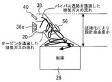
- FIG. 2 is an explanatory diagram for explaining the difference in the flow of the exhaust gas that has passed through the turbine of the turbocharger and the exhaust gas that has passed through the bypass passage, and FIG. It is explanatory drawing for demonstrating the difference in a fuel ratio fluctuation.
- the exhaust purification catalyst 26 tends to be arranged closer to the engine body side, that is, the turbine 36a side in order to improve the warm-up performance of the catalyst in response to exhaust regulations and the like. This proximity reduces the degree of design freedom.
- the exhaust gas that has passed through the turbine 36a reaches the air-fuel ratio sensor 56 immediately after being agitated by the turbine 36a, so that the gas flow is compared with the exhaust gas that has passed through the bypass passage 38. Tends to be made uniform around the air-fuel ratio sensor 56.
- the fluctuation waveform of the air-fuel ratio of the exhaust gas that has passed through the bypass passage 38 becomes substantially the same as that in the case of a naturally aspirated engine.
- the exhaust gas that has passed through the turbine 36a tends to diverge in the vector direction of the exhaust motion, there is a tendency that the amount of fluctuation (the fluctuation width) of the air-fuel ratio becomes small.
- the WGV 40 is closed (preferably fully closed) when performing the catalyst deterioration determination control.
- the bypass passage 38 is shut off, and only the exhaust gas that has passed through the turbine 36 a can reach the periphery of the air-fuel ratio sensor 56. Thereby, the flow of the exhaust gas and the fluctuation of the air-fuel ratio can always be stabilized around the air-fuel ratio sensor 56 without being affected by the supercharging control.
- the exhaust gas that has passed through the turbine 36a is made uniform as compared with the exhaust gas that has passed through the bypass passage 38, and since the fluctuation of the air-fuel ratio is small, the oxygen storage amount OSC measurement period (the aforementioned rich period) And the lean period) can be lengthened.
- the measured value of the oxygen storage amount OSC can be increased, the S / N ratio can be improved and a stable measured value can be obtained. Therefore, even in an engine equipped with a turbo, it is possible to accurately determine the deterioration of the catalyst 26, avoid a decrease in determination accuracy and erroneous determination, and improve reliability.
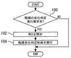
- FIG. 4 is a flowchart showing the control executed by the ECU in the first embodiment of the present invention.
- the routine shown in this figure is repeatedly executed during operation of the engine.
- step 100 it is determined whether or not a request for determining the deterioration of the exhaust purification catalyst 26 has occurred. This request is generated, for example, when a predetermined time has elapsed since the previous deterioration determination.
- step 102 in FIG. 4 shows a specific example of the determination time valve closing means in claim 1
- step 104 shows a specific example of the active air-fuel ratio control means and the deterioration determination means.
- Embodiment 2 a second embodiment of the present invention will be described with reference to FIGS.
- the present embodiment is characterized in that, in the same configuration as in the first embodiment, when the catalyst deterioration determination control is executed, the fluctuation range of the target air-fuel ratio is corrected.
- the same components as those in the first embodiment are denoted by the same reference numerals, and the description thereof is omitted.
- the target air-fuel ratio correction control is executed without closing the WGV 40.
- the fluctuation range of the target air-fuel ratio At controlled by the active air-fuel ratio control is corrected based on the opening degree of the WGV 40 and the intake air amount.
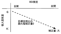
- FIG. 5 is a data map for determining the fluctuation correction amount of the target air-fuel ratio based on the opening degree of the WGV and the intake air amount in the second embodiment of the present invention.
- FIG. 6 is a timing chart showing a state where the fluctuation range of the target air-fuel ratio is corrected. Note that the determination execution flag in FIG. 6 is a flag that is set when the catalyst deterioration determination control is executed.
- the target air-fuel ratio fluctuation amount correction amount D is a correction amount for correcting the fluctuation amount (
- the target air-fuel ratio correction control as shown in FIG. 5, as the opening degree of the WGV 40 is smaller and the intake air amount of the engine is larger, the fluctuation amount correction amount D is increased, and the target air-fuel ratio fluctuation is increased. Reduce the width.
- the shake width correction amount D is set based on a state where the WGV 40 is held fully open and the intake air amount is a predetermined flow rate. That is, the deflection correction amount D is set to be zero in the reference state.
- the measured value of the oxygen storage amount OSC measured by the catalyst deterioration determination control has a characteristic of increasing as the opening of the WGV 40 is smaller and as the intake air amount is larger. Further, as can be seen from the calculation method described above, this measured value increases as the fluctuation width of the target air-fuel ratio At increases. For this reason, in the correction control described above, for example, when the measured value deviates in an increasing direction with respect to the reference state due to a change in the opening degree of the WGV or the intake air amount, Reduce the width.
- the influence of the change in the opening of the WGV or the intake air amount on the measured value can be compensated by the correction control of the target air-fuel ratio At. That is, the oxygen storage amount OSC can be stably measured under a certain condition (reference state) without being affected by these changes, and an accurate measurement value can be obtained. For this reason, even in an engine equipped with a turbo, it is possible to accurately determine the deterioration of the catalyst 26, avoid a decrease in determination accuracy and erroneous determination, and improve reliability.
- the fluctuation width of the target air-fuel ratio At is corrected in the decreasing direction, the fluctuation width of the actual air-fuel ratio Ar can be reduced accordingly, and the exhaust emission when the deterioration is detected can be improved.
- FIG. 7 is a flowchart showing the control executed by the ECU in the second embodiment of the present invention.
- the routine shown in this figure is repeatedly executed during operation of the engine.
- step 200 it is determined whether or not a deterioration determination execution request has been generated, as in the first embodiment.
- step 202 the catalyst deterioration determination control is executed while executing the active air-fuel ratio control.
- step 204 the opening degree of the WGV 40 set by the supercharging control or the like and the intake air amount detected by the air flow sensor 52 are read.
- step 206 by referring to the data of FIG. 5 based on these read values, the fluctuation correction amount D of the target air-fuel ratio is calculated, and the target air-fuel ratio At is corrected based on this calculated value. .
- step 202 in FIG. 7 shows a specific example of the active air-fuel ratio control means and the deterioration determination means in claim 2, and step 206 and FIG. 5 show the amplitude correction in claims 2 and 3. A specific example of the means is shown.
- Embodiment 3 a third embodiment of the present invention will be described with reference to FIGS.
- the present embodiment is characterized in that, in the same configuration as in the first embodiment, when the catalyst deterioration determination control is executed, the deterioration determination value is corrected.
- the same components as those in the first embodiment are denoted by the same reference numerals, and the description thereof is omitted.
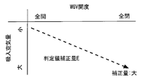
- FIG. 8 is a data map for determining the correction amount of the deterioration determination value based on the opening degree of the WGV and the intake air amount in the third embodiment of the present invention.
- FIG. 9 is a timing chart showing a state in which the deterioration determination value is corrected. Note that the determination execution flag in FIG. 9 is a flag that is set when the catalyst deterioration determination control is executed.
- the determination value correction amount E is used to correct the deterioration determination value S in a decreasing direction, and the deterioration determination value S decreases as the determination value correction amount E increases as shown in FIG.
- the determination value correction amount E is increased as the opening of the WGV 40 is smaller and the intake air amount of the engine is larger. Decrease.
- the determination value correction amount E is set with the state where the WGV 40 is kept fully open and the intake air amount is a predetermined flow rate as a reference state. That is, the determination value correction amount E is set to be zero in the reference state.
- the following operational effects can be obtained.
- the measured value of the oxygen storage amount OSC has a characteristic of increasing as the opening of the WGV 40 is smaller and as the intake air amount is larger.
- the deterioration determination value is used to prevent erroneous determination due to the shifted measured value.
- the oxygen storage amount OSC when the oxygen storage amount OSC is measured, even if a change in the opening degree of the WGV or a change in the intake air amount acts as a disturbance, the influence of these changes on the measurement value is compensated by the correction control of the deterioration determination value S. Can do. Thereby, the oxygen storage amount OSC can be stably measured under a certain condition (reference state), and the S / N ratio of the measured value against the disturbance can be improved. For this reason, almost the same as in the case of the second embodiment, even in an engine with a turbo, it is possible to accurately determine the deterioration of the catalyst 26 and avoid a decrease in determination accuracy and erroneous determination.
- FIG. 10 is a flowchart showing the control executed by the ECU in the third embodiment of the present invention.
- the routine shown in this figure is repeatedly executed during operation of the engine.
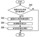
- step 300 it is determined whether or not a deterioration determination execution request has occurred, as in the first embodiment.
- step 302 the catalyst deterioration determination control is executed while executing the active air-fuel ratio control.
- step 304 as in the case of the second embodiment, the opening degree of the WGV 40 and the intake air amount are read.
- step 306 the data in FIG. 8 is referred to based on these read values.
- the determination value correction amount E is calculated.
- the deterioration determination value S is corrected based on the determination value correction amount E.
- step 302 in FIG. 10 shows a specific example of the active air-fuel ratio control means and the deterioration determination means in claim 4, and step 306 and FIG. 8 show the determination values in claims 4 and 5. A specific example of correction means is shown.
- the present invention is not limited to this, and the configuration in which the second and third embodiments are combined. It is good. That is, in the present invention, the correction of the fluctuation range of the target air-fuel ratio and the correction of the deterioration determination value may be performed together.
- the state in which the WGV 40 is fully opened is used as the reference state when correcting the fluctuation range and the deterioration determination value of the target air-fuel ratio.
- the present invention is not limited to this, and as the reference state, a state in which the WGV 40 is fully closed may be used, and further, a state in which the WGV 40 is held at a predetermined intermediate opening degree may be used.
Landscapes
- Engineering & Computer Science (AREA)
- Chemical & Material Sciences (AREA)
- Combustion & Propulsion (AREA)
- Mechanical Engineering (AREA)
- General Engineering & Computer Science (AREA)
- Health & Medical Sciences (AREA)
- Emergency Medicine (AREA)
- Exhaust Gas After Treatment (AREA)
- Electrical Control Of Air Or Fuel Supplied To Internal-Combustion Engine (AREA)
- Supercharger (AREA)
- Output Control And Ontrol Of Special Type Engine (AREA)
- Combined Controls Of Internal Combustion Engines (AREA)
Abstract
Description
尚、出願人は、本発明に関連するものとして、上記の文献を含めて、以下に記載する文献を認識している。
前記排気浄化触媒の上流側で前記排気通路に設けられたタービンを有し、排気圧を利用して吸入空気を過給するターボ過給機と、
前記タービンの上流側で前記排気通路から分岐し、前記タービンをバイパスして前記排気浄化触媒の上流側で前記排気通路に合流するバイパス通路と、
前記バイパス通路を流れる排気ガスの量を調整するウェイストゲートバルブと、
前記排気通路と前記バイパス通路との合流部位よりも下流側に配置され、前記排気浄化触媒の近傍で空燃比を検出する空燃比検出手段と、
理論空燃比を中心として目標空燃比をリッチ側及びリーン側に交互に変化させ、前記空燃比検出手段により検出される実空燃比が前記目標空燃比と一致するように前記実空燃比を制御するアクティブ空燃比制御手段と、
前記アクティブ空燃比制御手段により前記実空燃比を制御した状態で、前記目標空燃比と前記実空燃比とに基いて前記排気浄化触媒の酸素吸蔵量を計測し、当該計測値を所定の劣化判定値と比較することにより前記排気浄化触媒の劣化を判定する劣化判定手段と、
前記劣化判定手段により劣化判定を実行する場合に、前記ウェイストゲートバルブを閉弁する判定時閉弁手段と、を備えることを特徴とする。
前記排気浄化触媒の上流側で前記排気通路に設けられたタービンを有し、排気圧を利用して吸入空気を過給するターボ過給機と、
前記タービンの上流側で前記排気通路から分岐し、前記タービンをバイパスして前記排気浄化触媒の上流側で前記排気通路に合流するバイパス通路と、
前記バイパス通路を流れる排気ガスの量を調整するウェイストゲートバルブと、
前記排気通路と前記バイパス通路との合流部位よりも下流側に配置され、前記排気浄化触媒の近傍で空燃比を検出する空燃比検出手段と、
理論空燃比を中心として目標空燃比をリッチ側及びリーン側に交互に変化させ、前記空燃比検出手段により検出される実空燃比が前記目標空燃比と一致するように前記実空燃比を制御するアクティブ空燃比制御手段と、
前記アクティブ空燃比制御手段により前記実空燃比を制御した状態で、前記目標空燃比と前記実空燃比とに基いて前記排気浄化触媒の酸素吸蔵量を計測し、当該計測値を所定の劣化判定値と比較することにより前記排気浄化触媒の劣化を判定する劣化判定手段と、
前記劣化判定手段により劣化判定を実行する場合に、前記理論空燃比を中心とした前記目標空燃比の振れ幅を前記ウェイストゲートバルブの開度に基いて補正する振幅補正手段と、を備えることを特徴とする。
前記排気浄化触媒の上流側で前記排気通路に設けられたタービンを有し、排気圧を利用して吸入空気を過給するターボ過給機と、
前記タービンの上流側で前記排気通路から分岐し、前記タービンをバイパスして前記排気浄化触媒の上流側で前記排気通路に合流するバイパス通路と、
前記バイパス通路を流れる排気ガスの量を調整するウェイストゲートバルブと、
前記排気通路と前記バイパス通路との合流部位よりも下流側に配置され、前記排気浄化触媒の近傍で空燃比を検出する空燃比検出手段と、
理論空燃比を中心として目標空燃比をリッチ側及びリーン側に交互に変化させ、前記空燃比検出手段により検出される実空燃比が前記目標空燃比と一致するように前記実空燃比を制御するアクティブ空燃比制御手段と、
前記アクティブ空燃比制御手段により前記実空燃比を制御した状態で、前記目標空燃比と前記実空燃比とに基いて前記排気浄化触媒の酸素吸蔵量を計測し、当該計測値を所定の劣化判定値と比較することにより前記排気浄化触媒の劣化を判定する劣化判定手段と、
前記劣化判定手段により劣化判定を実行する場合に、前記劣化判定値を前記ウェイストゲートバルブの開度に基いて補正する判定値補正手段と、を備えることを特徴とする。
[実施の形態1の構成]
以下、図1及び図4を参照しつつ、本発明の実施の形態1について説明する。図1は、本発明の実施の形態1のシステム構成を説明するための全体構成図である。本実施の形態のシステムは、内燃機関としてのエンジン10を備えている。エンジン10の各気筒には、ピストン12により燃焼室14が形成されており、ピストン12は、エンジンのクランク軸16に連結されている。また、エンジン10は、各気筒に吸入空気を吸込む吸気通路18と、各気筒から排気ガスが排出される排気通路20とを備えている。吸気通路18には、吸入空気量を調整する電子制御式のスロットルバルブ22と、吸入空気を冷却するインタークーラ24とが設けられている。
この制御では、まず、理論空燃比(ストイキ)を中心として目標空燃比Atをリッチ側及びリーン側に交互に変化させる。これにより、目標空燃比Atは、ストイキを中心としてリッチ側及びリーン側に矩形状(クランク状)に振動する。そして、このように振動する目標空燃比Atに対して、空燃比センサ56により検出される実空燃比Arが一致するように、実空燃比Ar(燃料噴射量)を制御する。これにより、実空燃比Arは、目標空燃比Atに対して僅かな時間遅れをもって振動するようになる。また、アクティブ空燃比制御において、目標空燃比Atは、排気浄化触媒26の下流側に配置された酸素濃度センサ58の出力が反転するタイミングで切換えられる。
この制御は、エンジン10が定常運転状態で、かつ、排気浄化触媒26が活性化した状態において、アクティブ空燃比制御の実行中に排気浄化触媒26の劣化度合いを判定する。触媒劣化判定制御では、まず、下記(1)式により酸素吸蔵量の増分ΔOSCを算出する。なお、酸素吸蔵量の増分ΔOSCとは、ECU60によるセンサ出力のサンプリング周期毎に演算される酸素吸蔵量である。
次に、図4を参照して、上述した制御を実現するための具体的な処理について説明する。図4は、本発明の実施の形態1において、ECUにより実行される制御を示すフローチャートである。この図に示すルーチンは、エンジンの運転中に繰り返し実行されるものとする。図4に示すルーチンでは、まず、ステップ100において、排気浄化触媒26の劣化判定を行う要求が発生したか否かを判定する。この要求は、例えば前回の劣化判定から所定の時間が経過した場合等に発生するものである。
次に、図5乃至図7を参照して、本発明の実施の形態2について説明する。本実施の形態では、前記実施の形態1と同様の構成において、触媒劣化判定制御を実行する場合に、目標空燃比の振れ幅を補正することを特徴としている。なお、本実施の形態では、実施の形態1と同一の構成要素に同一の符号を付し、その説明を省略するものとする。
本実施の形態では、触媒劣化判定制御を実行する場合に、WGV40を閉弁させずに、目標空燃比の補正制御を実行する。そして、この補正制御では、アクティブ空燃比制御により制御される目標空燃比Atの振れ幅を、WGV40の開度及び吸入空気量に基いて補正する構成としている。図5は、本発明の実施の形態2において、目標空燃比の振れ幅補正量をWGVの開度及び吸入空気量に基いて決定するためのデータマップである。また、図6は、目標空燃比の振れ幅を補正した状態を示すタイミングチャートである。なお、図6中の判定実行フラグは、触媒劣化判定制御の実行時にセットされるフラグである。
次に、図7を参照して、上述した制御を実現するための具体的な処理について説明する。図7は、本発明の実施の形態2において、ECUにより実行される制御を示すフローチャートである。この図に示すルーチンは、エンジンの運転中に繰り返し実行されるものとする。図7に示すルーチンでは、まず、ステップ200において、実施の形態1と同様に、劣化判定の実行要求が発生したか否かを判定する。
次に、図8乃至図10を参照して、本発明の実施の形態3について説明する。本実施の形態では、前記実施の形態1と同様の構成において、触媒劣化判定制御を実行する場合に、劣化判定値を補正することを特徴としている。なお、本実施の形態では、実施の形態1と同一の構成要素に同一の符号を付し、その説明を省略するものとする。
本実施の形態では、触媒劣化判定制御を実行する場合に、WGV40を閉弁させずに、劣化判定値Sの補正制御を実行する。そして、この補正制御では、酸素吸蔵量OSCの計測値と比較する劣化判定値Sを、WGV40の開度及び吸入空気量に基いて補正する構成としている。図8は、本発明の実施の形態3において、劣化判定値の補正量をWGVの開度及び吸入空気量に基いて決定するためのデータマップである。また、図9は、劣化判定値を補正した状態を示すタイミングチャートである。なお、図9中の判定実行フラグは、触媒劣化判定制御の実行時にセットされるフラグである。
次に、図10を参照して、上述した制御を実現するための具体的な処理について説明する。図10は、本発明の実施の形態3において、ECUにより実行される制御を示すフローチャートである。この図に示すルーチンは、エンジンの運転中に繰り返し実行されるものとする。図10に示すルーチンでは、まず、ステップ300において、実施の形態1と同様に、劣化判定の実行要求が発生したか否かを判定する。
12 ピストン
14 燃焼室
16 クランク軸
18 吸気通路
20 排気通路
22 スロットルバルブ
24 インタークーラ
26 排気浄化触媒
28 燃料噴射弁
30 点火プラグ
32 吸気バルブ
34 排気バルブ
36 ターボ過給機
36a タービン
36b コンプレッサ
38 バイパス通路
40 ウェイストゲートバルブ
40a アクチュエータ
50 クランク角センサ
52 エアフローセンサ
54 吸気圧センサ
56 空燃比センサ(空燃比検出手段)
58 酸素濃度センサ
60 ECU
At 目標空燃比
Ar 実空燃比
S 劣化判定値
Claims (5)
- 内燃機関の排気通路に設けられ、酸素吸蔵能を有する排気浄化触媒と、
前記排気浄化触媒の上流側で前記排気通路に設けられたタービンを有し、排気圧を利用して吸入空気を過給するターボ過給機と、
前記タービンの上流側で前記排気通路から分岐し、前記タービンをバイパスして前記排気浄化触媒の上流側で前記排気通路に合流するバイパス通路と、
前記バイパス通路を流れる排気ガスの量を調整するウェイストゲートバルブと、
前記排気通路と前記バイパス通路との合流部位よりも下流側に配置され、前記排気浄化触媒の近傍で空燃比を検出する空燃比検出手段と、
理論空燃比を中心として目標空燃比をリッチ側及びリーン側に交互に変化させ、前記空燃比検出手段により検出される実空燃比が前記目標空燃比と一致するように前記実空燃比を制御するアクティブ空燃比制御手段と、
前記アクティブ空燃比制御手段により前記実空燃比を制御した状態で、前記目標空燃比と前記実空燃比とに基いて前記排気浄化触媒の酸素吸蔵量を計測し、当該計測値を所定の劣化判定値と比較することにより前記排気浄化触媒の劣化を判定する劣化判定手段と、
前記劣化判定手段により劣化判定を実行する場合に、前記ウェイストゲートバルブを閉弁する判定時閉弁手段と、
を備えることを特徴とする内燃機関の制御装置。 - 内燃機関の排気通路に設けられ、酸素吸蔵能を有する排気浄化触媒と、
前記排気浄化触媒の上流側で前記排気通路に設けられたタービンを有し、排気圧を利用して吸入空気を過給するターボ過給機と、
前記タービンの上流側で前記排気通路から分岐し、前記タービンをバイパスして前記排気浄化触媒の上流側で前記排気通路に合流するバイパス通路と、
前記バイパス通路を流れる排気ガスの量を調整するウェイストゲートバルブと、
前記排気通路と前記バイパス通路との合流部位よりも下流側に配置され、前記排気浄化触媒の近傍で空燃比を検出する空燃比検出手段と、
理論空燃比を中心として目標空燃比をリッチ側及びリーン側に交互に変化させ、前記空燃比検出手段により検出される実空燃比が前記目標空燃比と一致するように前記実空燃比を制御するアクティブ空燃比制御手段と、
前記アクティブ空燃比制御手段により前記実空燃比を制御した状態で、前記目標空燃比と前記実空燃比とに基いて前記排気浄化触媒の酸素吸蔵量を計測し、当該計測値を所定の劣化判定値と比較することにより前記排気浄化触媒の劣化を判定する劣化判定手段と、
前記劣化判定手段により劣化判定を実行する場合に、前記理論空燃比を中心とした前記目標空燃比の振れ幅を前記ウェイストゲートバルブの開度に基いて補正する振幅補正手段と、
を備えることを特徴とする内燃機関の制御装置。 - 前記振幅補正手段は、前記ウェイストゲートバルブの開度が小さいほど、前記目標空燃比の振れ幅を減少させる構成としてなる請求項2に記載の内燃機関の制御装置。
- 内燃機関の排気通路に設けられ、酸素吸蔵能を有する排気浄化触媒と、
前記排気浄化触媒の上流側で前記排気通路に設けられたタービンを有し、排気圧を利用して吸入空気を過給するターボ過給機と、
前記タービンの上流側で前記排気通路から分岐し、前記タービンをバイパスして前記排気浄化触媒の上流側で前記排気通路に合流するバイパス通路と、
前記バイパス通路を流れる排気ガスの量を調整するウェイストゲートバルブと、
前記排気通路と前記バイパス通路との合流部位よりも下流側に配置され、前記排気浄化触媒の近傍で空燃比を検出する空燃比検出手段と、
理論空燃比を中心として目標空燃比をリッチ側及びリーン側に交互に変化させ、前記空燃比検出手段により検出される実空燃比が前記目標空燃比と一致するように前記実空燃比を制御するアクティブ空燃比制御手段と、
前記アクティブ空燃比制御手段により前記実空燃比を制御した状態で、前記目標空燃比と前記実空燃比とに基いて前記排気浄化触媒の酸素吸蔵量を計測し、当該計測値を所定の劣化判定値と比較することにより前記排気浄化触媒の劣化を判定する劣化判定手段と、
前記劣化判定手段により劣化判定を実行する場合に、前記劣化判定値を前記ウェイストゲートバルブの開度に基いて補正する判定値補正手段と、
を備えることを特徴とする内燃機関の制御装置。 - 前記判定値補正手段は、前記ウェイストゲートバルブの開度が小さいほど、前記劣化判定値を減少させる構成としてなる請求項4に記載の内燃機関の制御装置。
Priority Applications (5)
| Application Number | Priority Date | Filing Date | Title |
|---|---|---|---|
| JP2012549563A JP5754446B2 (ja) | 2010-12-24 | 2010-12-24 | 内燃機関の制御装置 |
| PCT/JP2010/073424 WO2012086078A1 (ja) | 2010-12-24 | 2010-12-24 | 内燃機関の制御装置 |
| CN201080070314.9A CN103249927B (zh) | 2010-12-24 | 2010-12-24 | 内燃机的控制装置 |
| DE112010006081.9T DE112010006081T5 (de) | 2010-12-24 | 2010-12-24 | Steuervorrichtung für eine Brennkraftmaschine |
| US13/885,709 US9273593B2 (en) | 2010-12-24 | 2010-12-24 | Control apparatus for internal combustion engine |
Applications Claiming Priority (1)
| Application Number | Priority Date | Filing Date | Title |
|---|---|---|---|
| PCT/JP2010/073424 WO2012086078A1 (ja) | 2010-12-24 | 2010-12-24 | 内燃機関の制御装置 |
Publications (1)
| Publication Number | Publication Date |
|---|---|
| WO2012086078A1 true WO2012086078A1 (ja) | 2012-06-28 |
Family
ID=46313375
Family Applications (1)
| Application Number | Title | Priority Date | Filing Date |
|---|---|---|---|
| PCT/JP2010/073424 Ceased WO2012086078A1 (ja) | 2010-12-24 | 2010-12-24 | 内燃機関の制御装置 |
Country Status (5)
| Country | Link |
|---|---|
| US (1) | US9273593B2 (ja) |
| JP (1) | JP5754446B2 (ja) |
| CN (1) | CN103249927B (ja) |
| DE (1) | DE112010006081T5 (ja) |
| WO (1) | WO2012086078A1 (ja) |
Cited By (6)
| Publication number | Priority date | Publication date | Assignee | Title |
|---|---|---|---|---|
| JP2018105244A (ja) * | 2016-12-27 | 2018-07-05 | トヨタ自動車株式会社 | 内燃機関の制御装置及び内燃機関の制御装置の異常診断システム |
| US10094271B2 (en) | 2014-09-18 | 2018-10-09 | Honda Motor Co., Ltd. | Control apparatus for internal combustion engine |
| US10985608B2 (en) | 2016-12-13 | 2021-04-20 | General Electric Company | Back-up power system for a component and method of assembling same |
| JP2022106498A (ja) * | 2021-01-07 | 2022-07-20 | トヨタ自動車株式会社 | エンジン制御装置 |
| JPWO2023223504A1 (ja) * | 2022-05-19 | 2023-11-23 | ||
| WO2023238361A1 (ja) * | 2022-06-10 | 2023-12-14 | 日産自動車株式会社 | 内燃機関の制御方法および制御装置 |
Families Citing this family (7)
| Publication number | Priority date | Publication date | Assignee | Title |
|---|---|---|---|---|
| DE102011003108B4 (de) * | 2011-01-25 | 2015-06-11 | Continental Automotive Gmbh | Überprüfung einer Abgasklappe |
| EP2687709A4 (en) * | 2011-03-16 | 2017-01-11 | Toyota Jidosha Kabushiki Kaisha | Internal combustion engine control apparatus |
| DE102012205364A1 (de) * | 2012-04-02 | 2013-10-02 | Bosch Mahle Turbosysteme GmbH & Co. KG | Turbolader zum Einsatz in einer Brennkraftmaschine |
| JP5765350B2 (ja) * | 2013-02-04 | 2015-08-19 | トヨタ自動車株式会社 | 多気筒内燃機関の気筒間空燃比インバランス検出装置 |
| US10337430B2 (en) * | 2016-06-14 | 2019-07-02 | Ford Global Technologies, Llc | Method and system for determining air-fuel ratio imbalance |
| DE102019203093A1 (de) * | 2019-03-07 | 2020-09-10 | Robert Bosch Gmbh | Verfahren und Vorrichtung zur Diagnose von Komponenten eines Abgassystems in einem Motorsystem mit einem Verbrennungsmotor |
| JP7207271B2 (ja) * | 2019-11-12 | 2023-01-18 | トヨタ自動車株式会社 | 内燃機関の制御装置 |
Citations (3)
| Publication number | Priority date | Publication date | Assignee | Title |
|---|---|---|---|---|
| JP2009264184A (ja) * | 2008-04-23 | 2009-11-12 | Toyota Motor Corp | 触媒劣化診断装置 |
| WO2010058461A1 (ja) * | 2008-11-19 | 2010-05-27 | トヨタ自動車株式会社 | 内燃機関の制御装置 |
| JP2010159701A (ja) * | 2009-01-08 | 2010-07-22 | Toyota Motor Corp | 触媒劣化診断装置 |
Family Cites Families (6)
| Publication number | Priority date | Publication date | Assignee | Title |
|---|---|---|---|---|
| JP2003232246A (ja) * | 2002-02-08 | 2003-08-22 | Denso Corp | 内燃機関の空燃比制御装置 |
| JP4023440B2 (ja) * | 2003-12-02 | 2007-12-19 | トヨタ自動車株式会社 | 内燃機関の空燃比制御装置 |
| JP4645639B2 (ja) * | 2007-11-27 | 2011-03-09 | トヨタ自動車株式会社 | 排気浄化装置 |
| JP5212826B2 (ja) | 2009-02-03 | 2013-06-19 | トヨタ自動車株式会社 | 触媒異常診断装置 |
| JP2010185371A (ja) | 2009-02-12 | 2010-08-26 | Toyota Motor Corp | 触媒劣化診断装置 |
| US8491845B2 (en) * | 2009-09-10 | 2013-07-23 | Cummins Ip, Inc. | Low temperature selective catalytic reduction catalyst and associated systems and methods |
-
2010
- 2010-12-24 CN CN201080070314.9A patent/CN103249927B/zh not_active Expired - Fee Related
- 2010-12-24 US US13/885,709 patent/US9273593B2/en not_active Expired - Fee Related
- 2010-12-24 WO PCT/JP2010/073424 patent/WO2012086078A1/ja not_active Ceased
- 2010-12-24 DE DE112010006081.9T patent/DE112010006081T5/de not_active Withdrawn
- 2010-12-24 JP JP2012549563A patent/JP5754446B2/ja not_active Expired - Fee Related
Patent Citations (3)
| Publication number | Priority date | Publication date | Assignee | Title |
|---|---|---|---|---|
| JP2009264184A (ja) * | 2008-04-23 | 2009-11-12 | Toyota Motor Corp | 触媒劣化診断装置 |
| WO2010058461A1 (ja) * | 2008-11-19 | 2010-05-27 | トヨタ自動車株式会社 | 内燃機関の制御装置 |
| JP2010159701A (ja) * | 2009-01-08 | 2010-07-22 | Toyota Motor Corp | 触媒劣化診断装置 |
Cited By (11)
| Publication number | Priority date | Publication date | Assignee | Title |
|---|---|---|---|---|
| US10094271B2 (en) | 2014-09-18 | 2018-10-09 | Honda Motor Co., Ltd. | Control apparatus for internal combustion engine |
| US10985608B2 (en) | 2016-12-13 | 2021-04-20 | General Electric Company | Back-up power system for a component and method of assembling same |
| JP2018105244A (ja) * | 2016-12-27 | 2018-07-05 | トヨタ自動車株式会社 | 内燃機関の制御装置及び内燃機関の制御装置の異常診断システム |
| JP2022106498A (ja) * | 2021-01-07 | 2022-07-20 | トヨタ自動車株式会社 | エンジン制御装置 |
| JP7447824B2 (ja) | 2021-01-07 | 2024-03-12 | トヨタ自動車株式会社 | エンジン制御装置 |
| JPWO2023223504A1 (ja) * | 2022-05-19 | 2023-11-23 | ||
| JP7718589B2 (ja) | 2022-05-19 | 2025-08-05 | 日産自動車株式会社 | 三元触媒の酸素ストレージ量制御方法および装置 |
| WO2023238361A1 (ja) * | 2022-06-10 | 2023-12-14 | 日産自動車株式会社 | 内燃機関の制御方法および制御装置 |
| JPWO2023238361A1 (ja) * | 2022-06-10 | 2023-12-14 | ||
| JP7740546B2 (ja) | 2022-06-10 | 2025-09-17 | 日産自動車株式会社 | 内燃機関の制御方法および制御装置 |
| US12529330B2 (en) | 2022-06-10 | 2026-01-20 | Nissan Motor Co., Ltd. | Control method and control device for internal combustion engine |
Also Published As
| Publication number | Publication date |
|---|---|
| JPWO2012086078A1 (ja) | 2014-05-22 |
| CN103249927A (zh) | 2013-08-14 |
| US9273593B2 (en) | 2016-03-01 |
| DE112010006081T5 (de) | 2014-06-12 |
| CN103249927B (zh) | 2015-07-22 |
| US20130283783A1 (en) | 2013-10-31 |
| JP5754446B2 (ja) | 2015-07-29 |
Similar Documents
| Publication | Publication Date | Title |
|---|---|---|
| JP5754446B2 (ja) | 内燃機関の制御装置 | |
| US9027539B2 (en) | Control apparatus for internal combustion engine | |
| JP4583038B2 (ja) | 過給機付き内燃機関の過給圧推定装置 | |
| JP5360307B2 (ja) | 内燃機関の制御装置 | |
| US10174719B2 (en) | Control device for internal combustion engine | |
| JP2011185159A (ja) | 過給機付き内燃機関の異常診断装置 | |
| US10094271B2 (en) | Control apparatus for internal combustion engine | |
| WO2012077214A1 (ja) | Egr装置の異常検出装置 | |
| JP3768780B2 (ja) | 内燃機関の空燃比制御装置 | |
| WO2012077164A1 (ja) | 多気筒内燃機関の気筒間空燃比ばらつき異常検出装置 | |
| JP5267744B2 (ja) | 内燃機関の制御装置 | |
| JP5218669B2 (ja) | 内燃機関の制御装置 | |
| JP5660322B2 (ja) | 内燃機関のegr制御装置 | |
| JP2014227844A (ja) | 内燃機関の制御装置 | |
| JP2012145054A (ja) | 多気筒内燃機関の気筒間空燃比ばらつき異常検出装置 | |
| CN108691671B (zh) | Egr控制装置 | |
| JP5516349B2 (ja) | 内燃機関の制御装置 | |
| US20160369729A1 (en) | Control apparatus and control method for internal combustion engine | |
| JP5760931B2 (ja) | エンジンの制御装置 | |
| JP2007303380A (ja) | 内燃機関の排気制御装置 | |
| JP2008038625A (ja) | 内燃機関の排気浄化装置、及び方法 | |
| JP4151172B2 (ja) | ディーゼルエンジンの空燃比制御装置 | |
| JP2022083541A (ja) | 内燃機関の制御装置 |
Legal Events
| Date | Code | Title | Description |
|---|---|---|---|
| 121 | Ep: the epo has been informed by wipo that ep was designated in this application |
Ref document number: 10861012 Country of ref document: EP Kind code of ref document: A1 |
|
| ENP | Entry into the national phase |
Ref document number: 2012549563 Country of ref document: JP Kind code of ref document: A |
|
| WWE | Wipo information: entry into national phase |
Ref document number: 13885709 Country of ref document: US |
|
| WWE | Wipo information: entry into national phase |
Ref document number: 1120100060819 Country of ref document: DE Ref document number: 112010006081 Country of ref document: DE |
|
| 122 | Ep: pct application non-entry in european phase |
Ref document number: 10861012 Country of ref document: EP Kind code of ref document: A1 |