WO2012081067A1 - カチオン硬化型液晶シール剤、及び液晶表示素子 - Google Patents
カチオン硬化型液晶シール剤、及び液晶表示素子 Download PDFInfo
- Publication number
- WO2012081067A1 WO2012081067A1 PCT/JP2010/072327 JP2010072327W WO2012081067A1 WO 2012081067 A1 WO2012081067 A1 WO 2012081067A1 JP 2010072327 W JP2010072327 W JP 2010072327W WO 2012081067 A1 WO2012081067 A1 WO 2012081067A1
- Authority
- WO
- WIPO (PCT)
- Prior art keywords
- polymerization initiator
- liquid crystal
- mass
- manufactured
- parts
- Prior art date
- Legal status (The legal status is an assumption and is not a legal conclusion. Google has not performed a legal analysis and makes no representation as to the accuracy of the status listed.)
- Ceased
Links
Classifications
-
- G—PHYSICS
- G02—OPTICS
- G02F—OPTICAL DEVICES OR ARRANGEMENTS FOR THE CONTROL OF LIGHT BY MODIFICATION OF THE OPTICAL PROPERTIES OF THE MEDIA OF THE ELEMENTS INVOLVED THEREIN; NON-LINEAR OPTICS; FREQUENCY-CHANGING OF LIGHT; OPTICAL LOGIC ELEMENTS; OPTICAL ANALOGUE/DIGITAL CONVERTERS
- G02F1/00—Devices or arrangements for the control of the intensity, colour, phase, polarisation or direction of light arriving from an independent light source, e.g. switching, gating or modulating; Non-linear optics
- G02F1/01—Devices or arrangements for the control of the intensity, colour, phase, polarisation or direction of light arriving from an independent light source, e.g. switching, gating or modulating; Non-linear optics for the control of the intensity, phase, polarisation or colour
- G02F1/13—Devices or arrangements for the control of the intensity, colour, phase, polarisation or direction of light arriving from an independent light source, e.g. switching, gating or modulating; Non-linear optics for the control of the intensity, phase, polarisation or colour based on liquid crystals, e.g. single liquid crystal display cells
-
- C—CHEMISTRY; METALLURGY
- C08—ORGANIC MACROMOLECULAR COMPOUNDS; THEIR PREPARATION OR CHEMICAL WORKING-UP; COMPOSITIONS BASED THEREON
- C08G—MACROMOLECULAR COMPOUNDS OBTAINED OTHERWISE THAN BY REACTIONS ONLY INVOLVING UNSATURATED CARBON-TO-CARBON BONDS
- C08G85/00—General processes for preparing compounds provided for in this subclass
-
- C—CHEMISTRY; METALLURGY
- C09—DYES; PAINTS; POLISHES; NATURAL RESINS; ADHESIVES; COMPOSITIONS NOT OTHERWISE PROVIDED FOR; APPLICATIONS OF MATERIALS NOT OTHERWISE PROVIDED FOR
- C09K—MATERIALS FOR MISCELLANEOUS APPLICATIONS, NOT PROVIDED FOR ELSEWHERE
- C09K3/00—Materials not provided for elsewhere
- C09K3/10—Materials in mouldable or extrudable form for sealing or packing joints or covers
Definitions
- the present invention relates to a liquid crystal sealant, and more particularly to a light and / or heat cation curable liquid crystal sealant.
- a liquid crystal panel (liquid crystal display element) has a back substrate including a thin film transistor, a pixel electrode, an alignment film, and the like facing a front substrate including a color filter, an electrode, an alignment film, and the like, and encapsulates liquid crystal between both substrates. It is configured.
- a sealing agent is used for the purpose of bonding the two substrates.
- thermosetting sealant composed mainly of an epoxy-based thermosetting resin
- it is often cured at 150 ° C, but substrates with different temperature differences between the upper and lower substrates or different thermal expansion coefficients are attached to each other.
- a method of adding a curing catalyst such as an inorganic solid acid such as silica or an organic acid such as salicylic acid to an epoxy resin and performing a curing reaction at a low temperature of 40 ° C. or lower has been tried. Takes a long time and is not practical.
- a photocurable sealant mainly composed of acrylate or the like is suitable for a plastic substrate because it does not require heat for curing and can be cured in a short time.
- acrylate has a large cure shrinkage, its adhesiveness is weak and it may be peeled off by a simple impact or the like.
- a photo-thermosetting sealant that uses a photo-curing component and a thermo-curing component together, first semi-cured by photo-curing, and then fully cured by heating (usually using heating during annealing).
- the adhesiveness to the plastic substrate was weak and there was a problem in practical use.
- a photo-curing sealant having a light binary curing system (for example, see Patent Document 1) using a photocationic curability mainly composed of an epoxy or the like and an acrylate having a photoradical curability, heats the curing. Not only can it be cured in a short time, but the photo-ring-opening reaction can greatly improve the adhesion of the substrate to the organic protective layer and inorganic protective layers such as SiOx. it can.
- the photocationic polymerization initiator that is ionic and the acid generated during cation curing are eluted in the liquid crystal and the voltage holding ratio is lowered.
- a method for producing a liquid crystal panel using a glass substrate As a method for producing a liquid crystal panel using a glass substrate, a method called a dripping method using a photocuring thermosetting combined sealant has become mainstream as well as a vacuum injection method using a thermosetting sealant.
- the dropping method first, a rectangular seal pattern is formed on one of the two transparent substrates with electrodes by a dispenser. Next, fine droplets of liquid crystal are dropped onto the entire surface of the transparent substrate in an uncured state, and the other transparent substrate is stacked under reduced pressure, and the seal portion is irradiated with ultraviolet rays for temporary curing. Thereafter, heating is performed to perform main curing, and a liquid crystal panel is manufactured.
- Patent Document 3 proposes a sealing agent using a cationically polymerizable compound as a sealing agent that does not use a thermosetting agent. Sealing agents using such cationically polymerizable compounds are superior in storage stability compared to sealing agents using thermosetting agents, are excellent in low-temperature fast curing properties, and require a short time for curing. There are advantages such as time reduction.
- liquid crystal display elements in recent years tend to use liquid crystal display devices having a low driving voltage (low voltage type liquid crystal) due to consumer-oriented low power consumption. Since this low voltage type liquid crystal has a particularly large dielectric anisotropy, impurities are easily taken in, and the orientation of the liquid crystal is disturbed and the voltage holding ratio of the liquid crystal display element is remarkably reduced.
- Patent Document 4 discloses a dispersible microcarrier that supports and supports a photocatalytic ionic salt of an onium or organometallic complex cation and a halogen-containing complex of a metal or metalloid anion as a photocationic polymerization initiator.
- a supported initiator for radiation-activated polymerization of a cationically polymerizable compound in the absence of a non-reactive solvent that is insoluble in the cationically polymerizable compound is known, and the photoinitiator was used Photocationic curable compositions have been proposed.
- the problem to be solved by the present invention is to provide a cation curable liquid crystal sealing agent having excellent electrical properties and adhesiveness, and to provide a liquid crystal display element having an excellent voltage holding ratio using the cation curable liquid crystal sealing agent. There is to do.
- the present inventors have solved the above problems by using a cationic polymerization initiator supported on a dispersible microcarrier as a cationic curable composition.
- the light or thermal cationic polymerization initiator is an ionic compound
- the voltage holding ratio of the liquid crystal display element that can reduce the resistance value of the liquid crystal may be reduced.
- the present inventors have found that elution can be significantly reduced by supporting a cationic polymerization initiator on a dispersible microcarrier, and the liquid crystal can be used for disordered liquid crystal orientation or a decrease in voltage holding ratio of a display element. It has been found that a liquid crystal sealant that does not cause deterioration of characteristics can be obtained.
- the present invention provides a cationically curable liquid crystal sealing agent containing a cationically polymerizable compound and a photocationic polymerization initiator and / or a thermal cationic polymerization initiator supported on a dispersible microcarrier.
- the present invention also includes two substrates facing each other, a sealing agent provided between the substrates, and a liquid crystal sealed in a sealing region surrounded by the sealing material, and the cationic curing as the sealing agent Provided is a liquid crystal display element using a liquid crystal sealing agent.
- the sealant of the present invention it is possible to obtain a liquid crystal display element that is less likely to cause disorder of liquid crystal orientation or a decrease in voltage holding ratio of the display element even in the dropping method.
- the cationic polymerization initiator used in the present invention is supported on a dispersible microcarrier.
- the dispersible microcarriers used in the present invention are preferably granular and have a maximum dimension of less than about 50 micrometers, preferably in the range of 0.001 to 20 micrometers, and more preferably 0.01 to 5 micrometers. It is preferably a dispersible micromaterial that has a particle size in the meter and most preferably from 0.01 to 2 micrometers and is insoluble in the organic component of the sealant, i.e. essentially insoluble in measurable quantities.
- the range is preferably from 0.1 to 10000 m 2 / g, more preferably from 1 to 5000 m 2 / g, still more preferably from 10 to 2000 m 2 / g, because it is easy to make and inhibits the uniformity of polymerization. More preferred is 30 to 1500 m 2 / g, and most preferred is a range of 30 to 1200 m 2 / g.
- silicas such as fumed silica, precipitated silica and natural silica; diatomaceous earth; clays such as bentonite, kaolinite and attapulgus clay; aluminum, zirconium, titanium, antimony, iron, Oxides of metals such as nickel, zinc, tin, copper, carbonates and sulfates, or mixtures thereof; starches such as starch (ie corn starch), carbon black, graphite, diamond, polymers; polystyrene, polyvinyltoluene Latexes, such as latex, polyvinylprolidone, polyacrylic acid, polyacrylate, polymethacrylate, etc .; pigment particles, or dispersible micromaterials of appropriate size, with photocations on or in their surface Fine that can contain a polymerization initiator Cellulose (i.e., cotton, wood), such that carriers, for example finely ground, glass and the like.
- a polymerization initiator Cellulose (i.e., cotton,
- a basic solid substance described later as a dispersible microcarrier.
- a weak base is preferable to a strong base, or the density of basic groups on the surface of the basic solid is smaller. preferable.
- the basic solid used as the carrier has an appropriate basicity, it is possible to control the delayed curability (property of slowing the curing reaction rate) of the cationic polymerizable compound.
- the dispersible microcarriers transmit light to be used, for example, ultraviolet rays.
- a particularly suitable carrier is fumed silica, such as AEROSIL (Nippon Aerosil Co., Ltd.).
- the metal oxide having a particularly large specific surface area of the dispersible microcarrier examples include a mesoporous material synthesized using a surfactant such as MCM41 as a template.
- a surfactant such as MCM41 as a template.
- organic low molecular gels and mesoporous materials prepared using a higher order structure of amino acids such as collagen as a template can be mentioned.
- the material of the mesoporous material include silica, alumina, zirconia, titania, and the like.
- a photo cationic polymerization initiator As the cationic polymerization initiator used in the present invention, there are a photo cationic polymerization initiator and a thermal cationic polymerization initiator, which are composed of a metal- or metalloid halogen-containing complex anion, an onium cation and an organometallic complex cation.
- An ionic salt hereinafter referred to as an ionic salt.
- group VA, VIA, or VIIA atoms of the periodic table given group 15, group 16, and group 17 symbols especially phosphorus, antimony, bismuth, sulfur, nitrogen , And an adduct of an aromatic organic cation and an anion of an iodine atom.
- onium salts such as aromatic diazonium salts, aromatic iodonium salts, and aromatic sulfonium salts.
- the photocationic polymerization initiator used in the present invention is a photocatalytic ionic salt (hereinafter referred to as an ionic salt) comprising a halogen-containing complex anion of metal or metalloid, an onium cation and an organometallic complex cation.
- an ionic salt comprising a halogen-containing complex anion of metal or metalloid, an onium cation and an organometallic complex cation.
- onium salts such as aromatic diazonium salts, aromatic iodonium salts, and aromatic sulfonium salts.
- Examples of commercially available onium salts include optomer SP-150, optomer SP-151, optomer SP-170, optomer SP-171 (all manufactured by Adeka Corporation), UVE-1014 (General Electronics Co., Ltd.) ), Irgacure-261 (Ciba Geigy), Sun-Aid SI-60L, Sun-Aid SI-80L, UVI-6990 (Union Carbide), BBI-103, MPI-103, TPS-103, MDS-103, DTS- 103, NAT-103, NDS-103 (all manufactured by Midori Chemical Co., Ltd.), Sun-Aid SI-100L (all manufactured by Sanshin Chemical Industry Co., Ltd.), CI-2064, CI-2639, CI-2624, CI-2481 (all Also made by Nippon Soda Co., Ltd.), RHODORSIL PH OTOINITIATOR 2074 (manufactured by Rhone-Poulenc), CD-1012 (man
- optomer SP-150 is less likely to cause electrode corrosion due to onium salts
- optomer SP-170 is more likely to have effective curability
- RHODORSIL PHOTOINITIATOR 2074 is more preferable because it has less ionic impurities.
- the said cationic photopolymerization initiator may be used independently and may use 2 or more types together. Moreover, you may use together sensitizers, such as anthracene type and a thioxanthone type, as needed.
- the mixing ratio of the photocationic polymerization initiator is not particularly limited, but the acid generated by photoirradiation of the photocationic polymerization initiator supported on the dispersible microcarrier generally has an effect on the polymerizable compound more than usual. Since it tends to be difficult, it is preferable to increase the addition amount rather than the normal use amount. Specifically, it is preferably used in the range of 0.01 to 20 parts by mass with respect to 100 parts by mass of the photocationically polymerizable compound described later.
- the curability of the sealing agent of the present invention may be insufficient. If it exceeds 20 parts by mass, the acid generated from the photocationic polymerization initiator will convert the photopolymerizable compound. Since it becomes more than the amount necessary for the reaction, there is a possibility that an acid may penetrate into the liquid crystal from the sealing agent and the electrical characteristics of the liquid crystal may be deteriorated. More preferably, it is in the range of 0.03 to 10 parts by mass.
- Thermal cationic polymerization initiator examples include: Sun-Aid SI60L, Sun-Aid SI80L, Sun-Aid SI100L, Sun-Aid SI110L, Sun-Aid SI180L (all manufactured by Sanshin Chemical Industry Co., Ltd.), CP-66, CP-77 (both are ADEKA Corporation) and the like. However, these are also used as a photocationic polymerization initiator. Further, CP-66, CP-77 (both are ADEKA Co., Ltd.), etc. The said thermal cationic polymerization initiator may be used independently and may use 2 or more types together.
- the blending ratio of the thermal cationic polymerization initiator is not particularly limited, but the acid generated by the heat of the thermal cationic polymerization initiator supported on the dispersible microcarrier generally has less effect on the polymerizable compound than usual. Since there exists a tendency, it is preferable to increase addition amount rather than normal usage-amount. Specifically, it is used in the range of 0.01 to 20 parts by weight, preferably 0.03 to 20 parts by weight, and more preferably 0.1 to 20 parts by weight with respect to 100 parts by weight of the cationically polymerizable compound described later. It is preferable.
- the curability of the sealing agent of the present invention may be insufficient, and if it exceeds 20 parts by mass, the acid generated from the thermal cationic polymerization initiator will convert the cationically polymerizable compound. Since it becomes more than the amount necessary for the reaction, there is a possibility that an acid may penetrate into the liquid crystal from the sealing agent and the electrical characteristics of the liquid crystal may be deteriorated. More preferably, it is in the range of 0.03 to 10 parts by mass.
- a dispersible microcarrier carrying a cationic polymerization initiator comprises an ionic salt of a metal- or metalloid halogen-containing complex anion with an onium cation or an organometallic complex cation in a suitable solvent such as methylene chloride, methanol, It can be produced by dissolving in ethanol, propanol, acetone, water, nitromethane, toluene, xylene or the like or a mixed solvent thereof and mixing this solution with an appropriate amount of a dispersible carrier material. By removing the solvent, the photocationic polymerization initiator is supported on the surface of the dispersible microcarrier or in the fine voids on the surface.
- a suitable solvent such as methylene chloride, methanol
- the solvent may be removed by filtration.
- a method of removing by distillation is preferable.
- a photocationic polymerization initiator that is easily decomposed it is preferably distilled off at 100 ° C. or lower, preferably 60 ° C. or lower, more preferably 40 ° C. or lower.
- lyophilization is preferably used as a drying method for removing the solvent in which the cationic polymerization initiator is dissolved.
- redispersion of the dispersible carrier material can be prevented and a fine dispersible microcarrier can be obtained.
- the finer the microcarrier the more efficiently the curing reaction of the cationic polymerizable compound can proceed.
- freeze-drying is difficult, such as when the freezing point of the solvent is low or when the solid after freezing is difficult to sublime, add water to the solvent as appropriate and dry the solvent first at the temperature at which the water freezes. The remaining frozen water may be lyophilized and removed.
- the dispersible microcarrier is preferably porous, and the supported cationic polymerization initiator is preferably supported in the pores of the carrier. This is because the cationic polymerization initiator adsorbed outside the pores is highly likely to come into contact with the resin component of the sealing material or the liquid crystal, and the ionic cationic polymerization initiator is eluted to inhibit the insulating properties of the liquid crystal. It is preferable to wash and remove only the cationic polymerization initiator adsorbed outside the pores by some method. For this purpose, for example, the dispersible microcarrier carrying the cationic polymerization initiator may be removed with a solvent.
- the solvent to be used there is a solvent having a minimum solubility in the cationic polymerization initiator, but having an appropriate solubility that is not so large that the cationic polymerization initiator adsorbed in the pores is completely dissolved. preferable. It is necessary to select appropriately depending on the type of the dispersible carrier material and the cationic polymerization initiator. Increasing the number of washings removes the cationic polymerization initiator outside the pores, but also reduces the amount of cationic polymerization initiator inside the pores, so depending on the amount of cationic polymerization initiator remaining inside and outside the pores That is, the number of times of cleaning is determined according to curability and electrical characteristics.
- the amount of the dispersible microcarrier added is preferably in a range not exceeding 50% by mass of the cationic polymerizable compound. Specifically, it is used in the range of 0.1 to 100 parts by weight with respect to 100 parts by weight of the cationic polymerizable compound, preferably 0.1 to 50 parts by weight, more preferably 1 to 30 parts by weight. Part by mass is most preferred.
- the cationic polymerization initiator is preferably used in the range of 0.1 to 20 parts by mass with respect to 100 parts by mass of the cationic polymerizable compound as described above, the amount of the dispersible microcarrier used is the supported cation. It is preferable to use by calculating back from the amount of the polymerizable initiator.
- the optimum amount of the loading varies depending on the surface shape and surface area of the dispersible microcarrier. For example, when a large amount of the polymerization initiator is supported on a dispersible microcarrier having a small surface area, the polymerization initiator is laminated in a multilayer on the surface of the hollow structure of the dispersible microcarrier.
- the polymerization initiator of the layer becomes weaker in adsorption force, the polymerization initiator may be dissolved or dispersed on the polymerizable compound side. This is undesirable because it causes contamination of the liquid crystal and causes deterioration of electrical characteristics. Furthermore, it differs depending on whether the opening portion of the hollow structure is largely open to the outside or the bottleneck type. For example, when the opening of the hollow structure is opened to the outside, it is not possible to support a large amount for the above reasons, but there is an advantage that the acid generated from the polymerization initiator effectively acts on the polymerization of the polymerizable compound. .
- the amount of the polymerization initiator supported on the dispersible microcarrier is the amount expressed by the addition amount / the surface area of the dispersible microcarrier.
- the latter is estimated to correspond to 1/10 to 100 layers in terms of the average number of layers of the polymerization initiator molecules per unit area.
- the supported cationic polymerization initiator is difficult to re-elute. Specifically, as a result of an experiment in which the supported cationic polymerization initiator was re-eluted with acetone, 30-60, regardless of the type of the dispersible microcarrier used and the supported amount of the cationic polymerization initiator to be supported. It was suggested that mass% of the cationic polymerization initiator re-eluted into the solution (B), and therefore 70 to 40% by mass of the cationic polymerization initiator was bound to the silica with sufficient bonding strength. (See reference experiment below).
- the cationically polymerizable compound to be used is less soluble than acetone. Therefore, it is estimated that the cationic polymerization initiator supported on one end hardly remains in the cationically polymerizable compound and remains stable.
- Some dispersible microcarriers have a primary particle size of about several tens of nanometers, but often aggregate to form secondary aggregates of several hundred nm to several ⁇ m. In order to sufficiently exhibit the catalytic function of the cationic polymerization initiator supported on the dispersible microcarrier, it is desirable to disperse to the size of the primary particles as much as possible.
- a dispersible microcarrier carrying a cationic polymerization initiator is added to a cationically polymerizable compound as a dispersion medium in the form of powder and stirred by a mixer or a screw extruder, or a three-roll, kneader, biaxial extruder, etc. It can be dispersed by kneading. In order to obtain a finer dispersion state, it is also preferable to use a bead mill or the like.
- the photocationic polymerization initiator supported on the dispersible microcarrier, the photocationic polymerizable compound described later, and the microbeads that are the stirring particles (media) are stirred together, and the stirring particles are passed through.
- the stirring particles are passed through.
- (Cationically polymerizable compound) As the cationically polymerizable compound used in the present invention, known and commonly used epoxy groups, oxetanyl groups and vinyl ether groups which are generally used as polymerizable compounds capable of cationic polymerization in the presence of the cationic polymerization initiator. If it is a compound, there will be no limitation in particular. However, a compound having an oxetanyl group is preferably used only in a small amount because it is disadvantageous in adhesiveness to plastic because the amount of hydroxyl group produced by polymerization is small.
- Examples of the cationically polymerizable compound having one or more epoxy groups in one molecule include bisphenol A type epoxy resins (trade names “Epicron 850CRP”, “Epicron 850S”, “Epicron 1050”, “Epicron” manufactured by DIC Corporation).
- Examples of commercially available cationically polymerizable compounds having one or more vinyl ether groups include 4-vinyloxybutanol (trade name “Vinyl-4-hydroxybutyether” manufactured by BASF) and triethylene glycol divinyl ether (manufactured by ISP). Trade name “Rapi-Cure DVE-3”), 1,4-cyclohexanedimethanol divinyl ether (trade name “CHDVE” manufactured by Nippon Carbide Industries, Ltd.), and the like.
- Examples of the cationically polymerizable compound having one or more oxetanyl groups in one molecule include 3-ethyl-3- (phenoxymethyl) oxetane (trade name “OXT-211” manufactured by Toagosei Co., Ltd.), 3-ethyl -3- (cyclohexyl) methyloxetane (trade name “CHOX” manufactured by Toa Gosei Co., Ltd.) and the like.
- Examples of the compound having two or more oxetane rings include 1,4-bis [ ⁇ (3-ethyloxetane-1-yl) methoxy ⁇ methyl] benzene (trade name “OXT-121” manufactured by Toagosei Co., Ltd.), 1,3 -Bis [(3-ethyloxetane-3-yl) methoxy] benzene (trade name “OXT-223” manufactured by Toa Gosei Co., Ltd.), bis [1-ethyl (3-oxetanyl)] methyl ether (product of Toa Gosei Co., Ltd.) Name “OXT-221”), phenol novolac oxetane (trade name “PNOX-1009” manufactured by Toa Gosei Co., Ltd.), 4,4′-bis [ ⁇ (3-ethyloxetane-1-yl) methoxy ⁇ methyl] biphenyl (Ube) Product name “OX
- a polymerizable compound having an epoxy group having an aromatic ring is particularly preferable because cohesive force is obtained by utilizing the interaction between aromatic rings, which is advantageous for adhesion.
- bisphenol A type epoxy resin trade names “Epicron 850CRP”, “Epicron 850S”, “Epicron 1050”, “Epicron 1055”, “Epicron 4822”, manufactured by DIC Corporation
- bisphenol F type epoxy resin (DIC) Trade name “Epicron 830CRP”, “Epicron 830” manufactured by the company.
- bisphenol A type epoxy resin (trade name “Epiclon 850CRP” manufactured by DIC) and bisphenol F type epoxy resin (manufactured by DIC) (Trade name “Epiclon 830CRP”) is particularly preferred.
- DIC bisphenol F type epoxy resin
- the cationically polymerizable compound of the present invention may be used in combination with a radical curable composition (hereinafter referred to as a radical curable composition).
- a radical curable composition hereinafter referred to as a radical curable composition
- the radical curable composition is a composition containing a radical polymerizable compound and a radical polymerization initiator.
- the radical polymerizable compound is not particularly limited as long as it is a known and commonly used compound having a (meth) acryloyl group as commonly used in the field of UV curing, but when used for a liquid crystal panel seal, Those that are difficult to mix with liquid crystal can be used more preferably.
- (meth) acrylate such as dipentaerythritol penta, hexaacrylate, pentaerythritol tetraacrylate and the like, which are considered to have large curing shrinkage.
- the radically polymerizable compound which has a carboxylic acid group may react with an epoxy group during storage and may increase the viscosity of the composition rapidly, it is preferable to use only a small amount.
- Polyester (meth) acrylate having an ester bond in the main chain structure and having at least two (meth) acryloyl groups, epoxy (meth) acrylate obtained by modification with epichlorohydrin, ethyl oxide, propylene oxide, A (meth) acrylate modified with a cyclic lactone or the like can also be preferably used.
- an acrylate having a urethane group is used in combination with a cationic curing system, curing inhibition by the urethane group occurs, so it is preferable to use only a small amount.
- (meth) acrylate used in the present invention include, for example, glycerin monomethacrylate (trade name “Blemmer GLM” manufactured by NOF Corporation), acryloyloxyethyl phthalate (trade name “HOA-MPE” manufactured by Kyoeisha Chemical Co., Ltd.).
- (meth) acrylate modified with lactone and (meth) acrylate modified with rosin are particularly preferable because they make the curable composition flexible and improve adhesion.
- lactone-modified hydroxypivalate neopentyl glycol diacrylate (trade name “HX620” manufactured by Nippon Kayaku Co., Ltd.)
- lactone-modified BPA epoxy phthalate ester diacrylate (trade name “Evecryl 3708” manufactured by Daicel Cytec Co., Ltd.)
- Rosin-modified epoxy acrylate trade name “Beamset 101” manufactured by Arakawa Chemical Co., Ltd.
- the amount of the radical polymerizable compound used is not particularly limited as long as it does not impair the scope of the present invention. Specifically, it is preferably in the range of 20 to 70% by mass.
- radical photopolymerization initiators examples include benzophenone, 2,2-diethoxyacetophenone, benzyl, benzoyl isopropyl ether, benzyl dimethyl ketal, 1-hydroxycyclohexyl phenyl ketone, and thioxanthone. These radical photopolymerization initiators may be used alone or in combination of two or more.
- a maleimide compound having photoinitiating ability can also be used. Specific examples of the maleimide compound having photoinitiating ability include maleimide compounds described in, for example, JP-A Nos. 2000-19868 and 2004-070297.
- radical thermal polymerization initiators examples include peroxide-based or azo-based initiators.
- peroxide thermal polymerization initiator examples include 3,5,5-trimethylhexanoyl peroxide (trade name: Parroyl 355, manufactured by NOF Corporation), 2,4-dichlorobenzoyl peroxide (trade name: Nyper).
- Diacyl peroxides such as CS, manufactured by NOF Corporation, isobutyl peroxide (trade name: Parroyl IB, manufactured by NOF Corporation), dilauroyl peroxide (trade name: Parroyl L, manufactured by NOF Corporation); Methyl-3-methoxybutyl) peroxydicarbonate (trade name: Parroyl SOP, manufactured by NOF Corporation), di-2-methoxybutyl peroxydicarbonate (trade name: Parroyl MBP, manufactured by NOF Corporation), Di-2 -Ethylhexyl peroxydicarbonate (trade name: Parroyl OPP, manufactured by NOF Corporation), di-2-ethoxyethyl peroxydicarbonate (Trade name: Parroyl EEP, manufactured by NOF Corporation), diisopropyl peroxydicarbonate (trade name: Parroyl IPP, manufactured by NOF Corporation), bis- (4-t-butylcyclohexyl) peroxydicarbonate (trade name) Per
- azo thermal polymerization initiator for example, 2,2′-azobis (4-methoxy-2,4-dimethylvaleronitrile) (trade name: V-70, manufactured by Wako Pure Chemical Industries, Ltd.), 2,2′- Azobis (2-cyclopropylpropionitrile) (trade name: V-68, manufactured by Wako Pure Chemical Industries, Ltd.), 2,2′-azobis (2,4-dimethylvaleronitrile) (trade name: V-65, Wako Pure) 2,2'-azobis (2-methyl-N-phenylpropionamidine) (trade name: VA-545, manufactured by Wako Pure Chemical Industries), 2,2'-azobis [N- (4-Chlorophenyl) -2-methylpropionamidine] dihydrochloride (trade name: VA-546, manufactured by Wako Pure Chemical Industries, Ltd.), 2,2′-azobis [N- (4-hydroxyphenyl) -2-methylpropionamidine ] Drochloride (trade name: VA-548, 2,
- the radical polymerization initiators may be used alone or in combination of two or more. Moreover, it is although it does not specifically limit as a mixture ratio of this radical polymerization initiator, A preferable minimum is 0.1 mass part with respect to 100 mass parts of curable compositions, and a preferable upper limit is 20 mass parts. If it is less than 0.1 parts by mass, the curability of the sealing agent of the present invention may be insufficient. If it exceeds 10 parts by mass, a large amount of radical polymerization initiator that cannot be reacted remains in the liquid crystal. There is a possibility of melting. A more preferred lower limit is 0.3 parts by mass, and a more preferred upper limit is 10 parts by mass.
- a compound having both radical polymerizable groups and cationic polymerizable groups can also be used.
- the polymerizable compound having both radical polymerizable group and cationic polymerizable group include commercially available BPF epoxy half acrylate and BPA epoxy half acrylate (trade name “UVa1561” manufactured by Daicel Cytec Co., Ltd.) Examples thereof include compounds in which a part of the epoxy group of a compound having a plurality of epoxy groups is reacted with (meth) acrylic acid to form (meth) acryloyl. Among them, BPA epoxy half acrylate and BPF epoxy half acrylate are more preferable because of high dilution effect.
- a combination of a radical curing system and a cationic curing system specifically, a (meth) acryloyl group as a radical curing system and an epoxy group as a cationic curing system coexist in the composition.
- the epoxy group can be cationically polymerized and the (meth) acryloyl group can be radically polymerized and cured by light irradiation or heat treatment, so that it can be firmly bonded to the substrate.
- a cationic polymerization initiator that cationically polymerizes an epoxy group and a radical polymerization initiator that radically polymerizes a (meth) acryloyl group are used in the curable composition. Is preferred.
- the cationic curable adhesive of the present invention can further reduce metal corrosivity by using a basic solid substance in combination.
- Basic solid substance As the basic solid substance used in the present invention, any solid compound having a function of neutralizing or capturing an acid can be used. Since the polymerization reaction of the cationic polymerizable compound is caused by the acid generated from the cationic polymerization initiator, it is necessary to neutralize and supplement the excess acid after the polymerization has sufficiently proceeded with the acid. Since the basic solid substance in the present invention is used in the state of being included in the adhesive, it may inhibit cationic polymerization. Accordingly, the basic solid substance is required to be substantially insoluble in the cationic polymerizable compound. The solubility of the basic solid substance is preferably 0.02 parts by mass or less with respect to 100 parts by mass of the cationic polymerizable compound.
- the particle size of the basic solid substance is preferably fine in order to prevent the generated acid from leaking from the adhesive to the outside. Since the size of the particles is physically limited, when the basic solid material particles to be used are not agglomerated and remain primary particles, the particle size is preferably 0.01 to 50 ⁇ m, preferably 0.01 to 5 ⁇ m. More preferred is 0.01 to 1 ⁇ m. When the particles of the basic solid substance to be used are aggregated to form secondary particles, the size of the secondary particles is preferably in the above range. Further, when used as a basic solid substance for a sealing material of a liquid crystal display, 0.01 to 2 ⁇ m is preferable because of the limitation of the distance between two substrates.
- inorganic basic solid materials various inorganic salts (carbonates, phosphates, carboxylates, etc.), metal oxides, metal sulfides, metal nitrides, basic clay minerals, etc., and these inorganic solid surfaces are basic What was processed etc. are mentioned.
- glass beads alumina (activated alumina), zeolite, titanium oxide, zinc oxide, silica gel, tin oxide, zircon oxide, magnesium oxide, calcium oxide, metal sulfide Group of zinc sulfide, basic titanium nitride as a metal nitride, basic talc as clay minerals, magnesium hydroxide of the basic and the like as a metal hydroxide.
- basic solid substances basic glass beads, basic titanium oxide, basic zinc oxide, basic silica gel, basic tin oxide, basic zircon oxide, basic titanium nitride, basic zinc sulfide
- the precursor metal oxide, metal nitride, metal sulfide is treated with a silane coupling agent having a basic group such as an organic amino group or a nitrogen compound such as hexamethyldisilazane. It can be basic. However, the present invention is not limited to these.
- Organic basic solid substance can be synthesized by various methods, and a commercially available organic basic solid substance can also be used. Specific examples include polyethyleneimine epomine (manufactured by Nippon Shokubai Co., Ltd.).
- a basic clay mineral such as talc or a basic functional group
- a basic solid substance a basic clay mineral such as talc or a basic functional group
- Coupling treated with functional group-containing compound and beads coated with the polymer beads are preferred.
- basic viscosity minerals such as talc and silica into which basic functional groups are introduced are preferable. Since the basicity of the basic solid may inhibit the curing reaction of the cationic polymerizable compound, a weak base is preferable to a strong base, or a lower density of basic groups on the surface of the basic solid is preferable. . This is because it is desirable that the basic solid base gradually neutralizes the remaining acid after the acid generated by the cationic polymerization initiator has sufficiently caused the curing reaction of the cationic polymerizable compound.
- the cation coupling type liquid crystal sealing agent of this invention can also mix a well-known and usual silane coupling agent.
- silane coupling agents a silane coupling agent having a polymerizable group such as a (meth) acryloyl group or an epoxy group is copolymerized with a radical curable or cationic curable compound to obtain high adhesion. Is particularly preferable.
- silane coupling agent having a polymerizable group examples include 3- (meth) acryloyloxypropyltrimethoxysilane, 3-epoxyoxypropyltrimethoxysilane, and the like.
- examples of commercially available silane coupling agents having such a polymerizable group include, for example, trade names “KBM503”, “KBE503”, “KBM502”, “KBE502”, “KBM5102”, and “KBM5103” manufactured by Shin-Etsu Chemical Co., Ltd. , “KBM403” and the like.
- the amount used is preferably in the range of 0.1 to 10% by mass, particularly preferably in the range of 1 to 5% by mass with respect to the total amount of the curable composition. If the ratio of the silane coupling agent is less than 0.1% by mass, a sufficient adhesion effect may not be obtained, and if it exceeds 10% by mass, phase separation may occur. A more preferred lower limit is 0.5 parts by mass, and a more preferred upper limit is 5 parts by mass.
- the filler can be appropriately blended in addition to the dispersible microcarrier carrying the cationic polymerizable compound in the present invention.
- the filler is added for the purpose of improving the adhesiveness of the sealing agent of the present invention due to the stress dispersion effect and improving the linear expansion coefficient.
- talc talc, asbestos, silica, diatomaceous earth, smectite, bentonite, calcium carbonate, magnesium carbonate, alumina, montmorillonite, diatomaceous earth, magnesium oxide, titanium oxide, magnesium hydroxide, aluminum hydroxide, glass beads, barium sulfate, gypsum, calcium silicate Inorganic fillers such as talc, glass beads, sericite activated clay, bentonite, and organic fillers such as polyester fine particles, polyurethane fine particles, vinyl polymer fine particles, and acrylic polymer fine particles.
- the blending ratio of the filler is not particularly limited, but as a blending amount including the dispersible microcarrier of the present invention, a preferred lower limit is 1 part by weight and a preferred upper limit is 100 parts by weight with respect to 100 parts by weight of the curable composition. Part. When the amount is less than 1 part by mass, the effect of adding the filler is hardly obtained. When the amount exceeds 100 parts by mass, the handling property such as the drawability of the sealing agent of the present invention may be deteriorated. A more preferred lower limit is 5 parts by mass, and a more preferred upper limit is 50 parts by mass.
- the cation curable liquid crystal sealant of the present invention has a viscosity of 100 Pa ⁇ s or higher measured at 25 ° C. and 2 sec ⁇ 1 using an E type viscometer, and the liquid crystal for producing a liquid crystal display element by a dropping method described later is used. More preferably, it can be used as a sealant.
- it is less than 100 Pa ⁇ s, when the liquid crystal display element is manufactured by the dropping method, the shape of the seal pattern formed on the transparent substrate cannot be maintained, and the sealing agent component is eluted in the liquid crystal, resulting in liquid crystal contamination. May end up.
- a more preferred lower limit is 100 Pa ⁇ s, and a more preferred upper limit is 5000 Pa ⁇ s.
- the drawing property of the sealant of the present invention is not sufficient, and it may be difficult to produce a liquid crystal display element by a dropping method.
- the E-type viscometer for measuring the viscosity is not particularly limited, and, for example, “DV-III” manufactured by Brookfield can be used.
- the cation curable liquid crystal sealant of the present invention can be used as a sealant for sealing an injection port after injecting a liquid crystal material into the liquid crystal panel, in addition to the sealant for producing a liquid crystal panel.
- the liquid crystal panel for example, after applying the photocationic curable liquid crystal sealant of the present invention to either the front or back substrate provided with a thin film transistor, pixel electrode, alignment film, color filter, electrode, etc.
- the other substrate is bonded, and light is irradiated from the substrate surface side of the substrate or from the side surface of the substrate to cure the photocurable composition for a liquid crystal panel seal of the present invention.
- the injection port is sealed with a sealant, whereby a liquid crystal panel can be produced.
- the liquid crystal panel has a liquid crystal dropping method, that is, a step of forming a seal pattern on one of two transparent substrates with electrodes using the photocationic curable liquid crystal sealant of the present invention, and a fine droplet of liquid crystal. It can be obtained by performing the step of dropping and applying to the entire surface of the seal pattern frame, the step of overlaying and bonding the other transparent substrate through the seal pattern, and the step of irradiating the seal pattern with light in this order. .
- a liquid crystal dropping method that is, a step of forming a seal pattern on one of two transparent substrates with electrodes using the photocationic curable liquid crystal sealant of the present invention, and a fine droplet of liquid crystal. It can be obtained by performing the step of dropping and applying to the entire surface of the seal pattern frame, the step of overlaying and bonding the other transparent substrate through the seal pattern, and the step of irradiating the seal pattern with light in this order. .
- the photocationic curable liquid crystal sealant of the present invention does not cure immediately after being irradiated with ultraviolet rays, but exhibits a delayed curing property of curing after maintaining a viscous fluid state for a while, two transparent substrates with electrodes
- a step of forming a seal pattern using the photocationic curable liquid crystal sealant of the present invention a step of irradiating the seal pattern with light, and a drop of liquid crystal are applied to the entire surface of the seal pattern frame. It is also possible to obtain the above-described process and the process of superimposing the other transparent substrate and bonding them together via the seal pattern in this order.
- Examples of the cationic curable liquid crystal sealing agent exhibiting delayed curing include the cationic polymerizable compound and a composition of the compound and a reaction retarding agent. Although it does not specifically limit as this reaction retarder, For example, a polyol compound etc. can be used. By containing the reaction retarder, the pot life and the curing time after the cationic curable liquid crystal sealing agent of the present invention is irradiated with light or heat-treated can be controlled.
- aliphatic polyols are preferable, and examples of such aliphatic polyols include (poly) alkylene glycols and glycerins such as ethylene glycol, propylene glycol, polyethylene glycol, polypropylene glycol, and butylene glycol. , Polyglycerin, pentaerythritol, polycaprolactone polyol, crown ether and the like.
- the kind of the photocationic polymerization initiator supported on one dispersible microcarrier is not particularly limited, and those described above can be used.
- the cation curable liquid crystal sealant of the present invention is preferably applied using a dispenser or by a screen printing method. In that case, it is common to apply to a line width of 0.08 to 2 mm and a line height of 5 to 50 ⁇ m.
- the light used for curing the photocationically curable liquid crystal sealing agent of the present invention is preferably ultraviolet light or visible light, and particularly preferably light having a wavelength of 300 nm to 400 nm.
- the light source for example, a high-pressure mercury lamp, a metal halide lamp, or the like can be used. When the illuminance of the light source is 500 W / m 2 or more, it is preferable that curing is quick. If the light quantity to be irradiated is 20000 J / m 2 or more in terms of the integrated light quantity, it can be cured well.
- the photocationic curable liquid crystal sealant of the present invention shows good photocurability even in an air atmosphere, but when photocured in an inert gas atmosphere such as nitrogen, it can be cured with a small amount of accumulated light. Since it is possible, it is more preferable.
- Adeka optomer SP150 of ADEKA Corporation was used as a photocationic polymerization initiator.
- SP150 is a propion carbonate solution having a solid content concentration of 50%, and the amount (parts by mass) described later is a part by mass including a solvent.
- 1 part by mass of a cationic photopolymerization initiator “SP150” was added to 20 parts by mass of acetone and dissolved.
- the photocationic polymerization initiator (A) supported on the dispersible microcarrier (hereinafter referred to as the supported photocationic polymerization initiator ( A)) was obtained.
- the characteristic X-ray intensity ratio of silica and sulfur using a fluorescent X-ray analyzer estimate the content of the photocationic polymerization initiator from the sulfur content, and the content of the initiator (photocationic polymerization initiator) ) / (Supporting mass of silica + photocation polymerization initiator) was 28% by mass. Therefore, the supported amount of the photocationic polymerization initiator with respect to silica calculated from the value obtained from the fluorescent X-ray analyzer is 1.3 ⁇ 10 ⁇ 3 g / m 2 .
- the content ratio of the photocationic polymerization initiator is determined from the intensity ratio of the characteristic X-rays of silica and sulfur. (Loaded mass of photocationic polymerization initiator) / (silica + photocationic polymerization initiator) was 12% by mass. Accordingly, the supported amount of the photocationic polymerization initiator with respect to silica calculated from this content ratio is 4.5 ⁇ 10 ⁇ 4 g / m 2 .
- the silica-supported thermal cationic polymerization initiator after centrifugation was stirred in 100 parts by mass of ultrapure water, and water was removed with a centrifuge. This was repeated a total of 4 times, and the silica-supported thermal cationic polymerization initiator after centrifugation was vacuum dried at room temperature to obtain a supported thermal cationic polymerization initiator (C).
- C thermal cationic polymerization initiator
- MCM41 which is a mesoporous silica material
- a surfactant docosyltrimethylammonium chloride (C22TMACl)
- C22TMACl docosyltrimethylammonium chloride
- mesoporous material (c) excluding the template mesoporous material (c) excluding the template.
- the pore diameter and surface area of the mesoporous material were measured with an N2 adsorption device (Autosorb). The pore diameter was 4.6 nm and the specific surface area was 1080 m 2 / g.
- a photocationic polymerization initiator “SP150” 1 part by weight of a photocationic polymerization initiator “SP150” was dissolved in a mixed solvent composed of 16 parts by weight of acetone and 4 parts by weight of water.
- 1 part by mass of the mesoporous material (c) was added to the solution of “SP150” and dispersed in the solution using an ultrasonic disperser.
- the dispersion solution was vacuum-dried while maintaining the temperature at 0 ° C. or lower, and acetone was distilled off, followed by vacuum drying. After acetone is distilled off, it is vacuum-dried while the water is frozen, and so-called freeze-drying is performed.
- the following washing was performed. 20 parts by mass of the silica-supported photocationic polymerization initiator was stirred in 100 parts by mass of an ethyl acetate solution, and the ethyl acetate was removed with a centrifuge. This was repeated a total of 4 times, and then the silica-supported photocationic polymerization initiator after centrifugation was stirred in 100 parts by mass of ultrapure water, and water was removed with a centrifuge.
- the silica-supported photocationic polymerization initiator after centrifugation was vacuum dried at room temperature to obtain a supported photocationic polymerization initiator (D).
- the content ratio of the photocationic polymerization initiator is determined from the intensity ratio of the characteristic X-rays of silica and sulfur. (Loaded mass of photocationic polymerization initiator) / (silica + photocationic polymerization initiator) The supported mass) was 18% by mass. Accordingly, the supported amount of the photocationic polymerization initiator with respect to silica calculated from this content ratio is 2.0 ⁇ 10 ⁇ 4 g / m 2 .
- This is designated as a supported photocationic polymerization initiator (E).
- the content ratio of the photocationic polymerization initiator is determined from the intensity ratio of the characteristic X-rays of silica and sulfur. (Loaded mass of photocationic polymerization initiator) / (silica + photocationic polymerization initiator) ) was 62%. Accordingly, the supported amount of the photocationic polymerization initiator with respect to silica calculated from this content ratio is 5.4 ⁇ 10 ⁇ 3 g / m 2 .
- the content ratio of the photocationic polymerization initiator is determined from the intensity ratio of the characteristic X-rays of silica and sulfur. (Loaded mass of photocationic polymerization initiator) / (silica + photocationic polymerization initiator) The supported mass) was 4% by mass. Therefore, the supported amount of the photocationic polymerization initiator with respect to silica calculated from this content is 3.9 ⁇ 10 ⁇ 5 g / m 2 .
- the following washing was performed to remove the initiator adsorbed outside the pores from the supported photocationic polymerization initiator after drying.
- 20 parts by mass of the silica-supported photocationic polymerization initiator was stirred in 100 parts by mass of an ethyl acetate solution, and the ethyl acetate was removed with a centrifuge. This was repeated a total of 4 times, and then the silica-supported photocationic polymerization initiator after centrifugation was stirred in 100 parts by mass of ultrapure water, and water was removed with a centrifuge. This was repeated a total of 4 times, and the supported photocationic polymerization initiator after centrifugation was vacuum dried at room temperature to obtain a supported photocationic polymerization initiator (G).
- G supported photocationic polymerization initiator
- the content ratio of the photocationic polymerization initiator is determined from the intensity ratio of the characteristic X-rays of silica and sulfur. (Loaded mass of photocationic polymerization initiator) / (silica + photocationic polymerization initiator) The supported mass) was 2% by mass. Therefore, the supported amount of the photocationic polymerization initiator with respect to silica calculated from this content ratio is 4.1 ⁇ 10 ⁇ 4 g / m 2 .
- the content ratio of the photocationic polymerization initiator is determined from the intensity ratio of the characteristic X-rays of silica and sulfur. (Loaded mass of photocationic polymerization initiator) / (silica + photocationic polymerization initiator) The supported mass) was 0.1% by mass. Therefore, the supported amount of the photocationic polymerization initiator with respect to silica calculated from this content is 9.3 ⁇ 10 ⁇ 7 g / m 2 .
- Example 1 2 parts by weight of the supported photocationic polymerization initiator (A) is added to 22 parts by weight of an epoxy monomer “EXA850crp” manufactured by DIC Corporation, and mixed using a rotating / revolving mixer-THINKY AR250 to obtain a sealing agent (A). It was. At this time, the cationic polymerization initiator is 2.5 parts by mass and the dispersible microcarrier is 6.5 parts by mass with respect to 100 parts by mass of the cationic polymerizable compound.
- the liquid crystal of Example 1 using the sealant (A) exhibited the same voltage holding ratio as that of the liquid crystal of Reference Example 2 alone.
- Comparative Example 1 in which the photocationic polymerization initiator and silica were separately added to the epoxy monomer without being supported on silica, and Comparative Example 2 in which only the photocationic polymerization initiator was added were lower than the voltage holding ratio of Reference Example 2. It was suggested that the cationic photopolymerization initiator was eluted in the liquid crystal. Note that the voltage holding ratio of Reference Example 1 in which only the epoxy monomer is added is also lower than the voltage holding ratio of only the liquid crystal of Reference Example 2. This suggests that the epoxy monomer itself also contains a factor that decreases the voltage holding ratio.
- Example 1 of the present application is higher than the voltage holding ratio of Reference Example 1, and from this, the initiation of photocationic polymerization carried on the dispersible microcarrier (of Example 1) of the present invention is started. It is suggested that the agent can also adsorb impurities and the like present in the monomer.
- Example 2 70 parts of epoxy monomer “EXA850crp” manufactured by DIC Corporation, 30 parts of 1,6-hexanediol diglycidyl ether “Denacol EX-212-L” manufactured by Nagase ChemteX Corporation, and silane system manufactured by Shin-Etsu Chemical Co., Ltd. 5 parts of the coupling agent “KBM403” was added and mixed using a rotating / revolving mixer THINKY AR250 until uniform. Next, 9 parts by mass of the supported photocationic polymerization initiator (B) was added and kneaded with three rolls to obtain a sealing agent (B). At this time, the cationic polymerization initiator is 1.1 parts by mass and the dispersible microcarrier is 7.9 parts by mass with respect to 100 parts by mass of the cationic polymerizable compound.
- One glass substrate “RZ-B107N1N” with ITO manufactured by EHC was sprayed with 5% ethanol dispersion of spacer “LH11S” manufactured by Hayakawa Rubber.
- the sealing agent (B) was applied to another glass substrate with ITO with a dispenser so that the sealing liquid width of the finally obtained liquid crystal panel was about 1 mm.
- the sealing agent (B) was applied so as to form a rectangular drawing line so as to surround the electrode inside.
- the sealant (B) was irradiated with ultraviolet rays of 500 W / m 2 for 20 seconds using a high-pressure metal halide lamp.
- liquid crystal “PA-0211CA033” manufactured by DIC Corporation is dropped inside the rectangular sealant (B), and the spacer is made to face the sprayed glass substrate.
- a laminated liquid crystal panel was prepared. This liquid crystal panel was held in a constant temperature and humidity chamber at a temperature of 60 ° C. and a humidity of 90% for 480 hours, and then the voltage holding ratio was measured. The voltage holding ratio was obtained by applying an initial voltage of 5 V AC at 23 ° C. for 64 microseconds, obtaining a voltage ratio before and after a frame time of 167 milliseconds, and multiplying this by 100. The results are shown in Table 2.
- Example 3 70 parts of epoxy monomer “EXA850crp” manufactured by DIC Corporation, 30 parts of 1,6-hexanediol diglycidyl ether “Denacol EX-212-L” manufactured by Nagase ChemteX Corporation, and silane system manufactured by Shin-Etsu Chemical Co., Ltd. 5 parts of the coupling agent “KBM403” was added and mixed using a rotating / revolving mixer THINKY AR250 until uniform. Next, 9 parts by mass of a supported thermal cationic polymerization initiator (C) was added and kneaded with three rolls to obtain a sealing agent (C).
- C supported thermal cationic polymerization initiator
- the cationic polymerization initiator is 0.8 part by mass and the dispersible microcarrier is 8.2 parts by mass with respect to 100 parts by mass of the cationic polymerizable compound.
- One glass substrate “RZ-B107N1N” with ITO manufactured by EHC was sprayed with 5% ethanol dispersion of spacer “LH11S” manufactured by Hayakawa Rubber.
- the sealing agent (C) was applied to another glass substrate with ITO with a dispenser so that the width of the sealing agent (C) of the finally obtained liquid crystal panel was about 1 mm.
- the sealing agent (C) was applied so as to form a rectangular drawing line so as to surround the electrode inside. This was heat-treated at 120 ° C. for 60 seconds.
- Example 4 70 parts of epoxy monomer “EXA850crp” manufactured by DIC Corporation, 30 parts of 1,6-hexanediol diglycidyl ether “Denacol EX-212-L” manufactured by Nagase ChemteX Corporation, and silane system manufactured by Shin-Etsu Chemical Co., Ltd. 5 parts of the coupling agent “KBM403” was added and mixed using a rotating / revolving mixer THINKY AR250 until uniform. Next, 9 parts by mass of the supported photocationic polymerization initiator (D) was added and kneaded with three rolls to obtain a sealing agent (D).
- D supported photocationic polymerization initiator
- the cationic polymerization initiator is 1.6 parts by mass and the dispersible microcarrier is 7.4 parts by mass with respect to 100 parts by mass of the cationic polymerizable compound.
- the voltage holding ratio was measured in the same manner as in Example 2, and the results are shown in Table 2.
- Example 5 70 parts of epoxy monomer “EXA850crp” manufactured by DIC Corporation, 30 parts of 1,6-hexanediol diglycidyl ether “Denacol EX-212-L” manufactured by Nagase ChemteX Corporation, and silane system manufactured by Shin-Etsu Chemical Co., Ltd. 5 parts of the coupling agent “KBM403” was added and mixed using a rotating / revolving mixer THINKY AR250 until uniform. Next, 9 parts by mass of the supported photocationic polymerization initiator (E) was added and kneaded with three rolls to obtain a sealant (E).
- E supported photocationic polymerization initiator
- the cationic polymerization initiator is 5.6 parts by mass and the dispersible microcarrier is 3.4 parts by mass with respect to 100 parts by mass of the cationic polymerizable compound.
- the voltage holding ratio was measured in the same manner as in Example 2, and the results are shown in Table 2.
- Example 6 70 parts of epoxy monomer “EXA850crp” manufactured by DIC Corporation, 30 parts of 1,6-hexanediol diglycidyl ether “Denacol EX-212-L” manufactured by Nagase ChemteX Corporation, and silane system manufactured by Shin-Etsu Chemical Co., Ltd. 5 parts of the coupling agent “KBM403” was added and mixed using a rotating / revolving mixer THINKY AR250 until uniform. Next, 9 parts by mass of the supported photocationic polymerization initiator (F) was added and kneaded with three rolls to obtain a sealant (F).
- F supported photocationic polymerization initiator
- the cationic polymerization initiator is 0.4 parts by mass and the dispersible microcarrier is 8.6 parts by mass with respect to 100 parts by mass of the cationic polymerizable compound.
- the voltage holding ratio was measured in the same manner as in Example 2, and the results are shown in Table 2.
- Example 7 70 parts of epoxy monomer “EXA850crp” manufactured by DIC Corporation, 30 parts of 1,6-hexanediol diglycidyl ether “Denacol EX-212-L” manufactured by Nagase ChemteX Corporation, and silane system manufactured by Shin-Etsu Chemical Co., Ltd. 5 parts of the coupling agent “KBM403” was added and mixed using a rotating / revolving mixer THINKY AR250 until uniform. Next, 9 parts by mass of the supported photocationic polymerization initiator (G) was added and kneaded with three rolls to obtain a sealing agent (G).
- G supported photocationic polymerization initiator
- the cationic polymerization initiator is 0.2 parts by mass and the dispersible microcarrier is 8.8 parts by mass with respect to 100 parts by mass of the cationic polymerizable compound.
- the voltage holding ratio was measured in the same manner as in Example 2, and the results are shown in Table 2.
- Example 8 70 parts of epoxy monomer “EXA850crp” manufactured by DIC Corporation, 30 parts of 1,6-hexanediol diglycidyl ether “Denacol EX-212-L” manufactured by Nagase ChemteX Corporation, and silane system manufactured by Shin-Etsu Chemical Co., Ltd. 5 parts of the coupling agent “KBM403” was added and mixed using a rotating / revolving mixer THINKY AR250 until uniform. Next, 9 parts by mass of the supported photocationic polymerization initiator (H) was added and kneaded with three rolls to obtain a sealant (H).
- H supported photocationic polymerization initiator
- the cationic polymerization initiator is 0.01 part by mass and the microcarrier is 8.8 parts by mass with respect to 100 parts by mass of the cationic polymerizable compound.
- the voltage holding ratio was measured in the same manner as in Example 2, and the results are shown in Table 2.
- Example 9 2 parts by weight of supported cationic photopolymerization initiator (A) 10 parts by weight of epoxy monomer “Epicoat 828”, 10 parts by weight “Epicoat 807”, 2.5 parts by weight of Mitsubishi Chemical Corporation It added to company "PTMG1000", it mixed using the rotation-revolution mixer THINKY AR250, and it was set as the sealing agent (I).
- Two glass substrates RS-B107M1N (with a rubbed alignment film and with ITO) made by EHC were prepared, and one of them was sprayed with a 5% ethanol dispersion of a spacer “LH11S” made by Hayakawa Rubber.
- the sealing agent (I) was applied to another glass substrate in a rectangular shape with a seal width of about 1 mm on the outer edge of the substrate using a dispenser. Thereafter, the sealant part was irradiated with ultraviolet rays of 500 W / m 2 for 40 seconds using a high-pressure meta-hara lamp. Next, an appropriate amount of liquid crystal “PA-0211CA033” manufactured by DIC Corporation is dropped inside the rectangular upper sealant on the substrate under vacuum, and the rubbing directions of the two glass substrates are orthogonalized to produce a bonded cell. did.
- the cell was returned to the atmosphere, and the interval between the substrates became the size of the spacer, and was allowed to stand for 1 hour until the sealant (I) was delayed cured to produce a TN type liquid crystal panel.
- This liquid crystal panel was sandwiched between two orthogonal polarizing plates with the optical axis aligned, to prepare a liquid crystal display element. When no voltage was applied, the display appeared transparent and bright, and when the voltage was applied, the electrode portion of the cell did not transmit light and dark display, indicating a good display state.
- two EHC glass substrates RS-B107M1N (with a rubbed alignment film, with ITO) were prepared, and one of them was sprayed with a 5% ethanol dispersion of a spacer “LH11S” manufactured by Hayakawa Rubber. .
- the sealing agent (H3) was applied to another glass substrate in a rectangular shape with a seal width of about 1 mm on the outer edge of the substrate using a dispenser. Thereafter, the sealant part was irradiated with ultraviolet rays of 500 W / m 2 for 40 seconds using a high pressure meta-hara lamp.
- Example 9 An opaque portion appeared in the periphery of the sealant without applying a voltage, and when the voltage was applied, a dark display of a part of the electrode portion appeared gray.
- a comparison between Example 9 and Comparative Example 3 showed that the sealant produced by the method of the present invention had little liquid crystal contamination. This is presumably because the amount of the photocation polymerization initiator that leaks from the sealing agent and contaminates the liquid crystal is small.
- the other supported photocationic polymerization initiators were prepared by appropriately changing the dispersible microcarriers used under the same conditions as described above and the supported amount of the photocationic polymerization initiator to be supported. Similarly, “eluting amount of polymerization initiator” was measured. The results are shown in Table 3.
- Total amount of polymerization initiator in Table 3 represents the mass of the photocationic polymerization initiator used in the supported photocationic polymerization initiator (A) and other photocationic polymerization initiators. Therefore, (eluting amount of polymerization initiator) / (total amount of polymerization initiator) indicates a ratio of mass of the photocationic polymerization initiator re-eluted in the solution (B), that is, acetone. From this result, 30 to 60% of the photocationic polymerization initiator was re-eluted into the solution (B) regardless of the type of the dispersible microcarrier used and the amount of the photocationic polymerization initiator to be supported. Therefore, it was suggested that 70 to 40% of the photocationic polymerization initiator was bound to the silica with a sufficient binding force.
- the basic solid substance (1) was prepared by introducing basic functional groups on the surface of fumed silica.
- fumed silica R976S manufactured by Nippon Aerosil Co., Ltd. was used.
- the production conditions will be described below.
- the mass ratio of the composition of each example is summarized in Table-1.
- ⁇ -aminopropyltriethoxysilane LS3150, Shin-Etsu Chemical Co., Ltd.
- the dissolution amount is shown in Table-1.
- Fumed silica (100 parts by mass of R976S manufactured by Nippon Aerosil Co., Ltd.) was immersed in the solution and mixed for 10 minutes with an ultrasonic dispersing device. This solution was heated on a hot plate heated to 150 ° C. for 1.5 hours. The powder was obtained by processing. In order to remove the unreacted material and / or the polymer of the silane coupling agent not bonded to the fumed silica surface, 100 parts by mass of this powder was dispersed in 2000 parts by mass of ethyl alcohol and 10 minutes by an ultrasonic treatment apparatus. After shaking, the powder was obtained by centrifugation. This washing was repeated two more times. This powder was dried with hot air at 80 ° C. for 4 hours to obtain a basic solid substance (1).
- Example 10 100 parts by mass of the sealant (D) described in Example 4 was mixed with 2.5 parts by mass of the basic solid substance (1) using a rotating / revolving mixer THINKY AR250, and the sealant (J )
- Example 11 Using 100 parts by mass of the sealant (D) described in Example 4, 20 parts by mass of this and a commercially available talc “Microlite (manufactured by Takehara Chemical Industry Co., Ltd.)” were used using a rotating / revolving mixer THINKY AR250. And mixed to obtain a sealant (K).
- the pH of the extracted water from the adhesive was measured as follows. After irradiating the adhesive with ultraviolet rays, in order to quantify the acid generated from the photoacid generator leached out from the adhesive, the adhesive irradiated with ultraviolet rays was immersed in ultrapure water and the pH was measured. In order to perform this measurement, 0.5 g of the adhesive is put into a glass container having a bottom area of 4.2 cm 2 , the lid of the glass container is removed, and ultraviolet rays having an intensity of 500 W / m 2 are applied from above to 20000 J / m 2. Irradiated.
- the pH of the extracted water was 5 or more, indicating that the basic solid substance neutralized or captured the acid generated from the photoacid generator.
- Electrode corrosion acceleration test For the sealing agents (J) and (K) of Examples 10 and 11, an electrode corrosion acceleration test was performed.
- the sealing agents (J) and (K) were applied to a comb-tooth electrode cell with an applicator so as to have a film thickness of 10 ⁇ m, and cured by irradiation with ultraviolet rays (intensity 50 mW / cm 2) for 40 seconds.
- the comb electrode is made of chromium, and the electrode width is 10 ⁇ m.
- the comb-shaped electrodes are divided into two systems and are opposed to each other, and are combined so that the comb teeth are nested, and the distance between the electrodes is 10 ⁇ m.
- Example 12 Liquid crystal panel production by dripping method
- Two glass substrates RS-B107M1N with a rubbed alignment film and with ITO
- ITO ionization film
- a spacer “LH11S” made by Hayakawa Rubber
- the sealant (J) produced in Example 10 was applied to another glass substrate in a rectangular shape with a seal width of about 1 mm on the outer edge of the substrate using a dispenser, and a high-pressure meta-hara lamp was used. Then, the sealant part was irradiated with UV of 500 W / m 2 for 40 seconds.
- liquid crystal “PA-0211CA033” manufactured by DIC Corporation is dropped inside the rectangular sealant on the substrate under vacuum, and a bonding cell is produced by making the rubbing directions of the two glass substrates orthogonal to each other. did.
- This cell was returned to atmospheric pressure to produce a TN type liquid crystal panel.
- This liquid crystal panel was sandwiched between two orthogonal polarizing plates with the optical axis aligned, to prepare a liquid crystal display element. When no voltage was applied, the display appeared transparent and bright, and when the voltage was applied, the electrode portion of the cell did not transmit light and dark display, indicating a good display state.
- a liquid crystal “PA-0211CA033” manufactured by DIC Corporation was injected into a two-hole cell under vacuum, and the liquid crystal composition was masked so as not to be directly exposed to ultraviolet rays. Then, two holes were used with a sealant (J) or (K) Was sealed and re-irradiated with a UV light of 500 W / m 2 for 40 seconds using a high-pressure metal halide lamp in a nitrogen atmosphere to prepare a liquid crystal panel.
- the liquid crystal panel produced by the above method was subjected to a 60 ° C. and 90% RH wet heat exposure test, and the voltage holding ratio after 120 hours was measured. The voltage holding ratio was calculated by applying an initial voltage of 5 V AC to the liquid crystal panel at 24 ° C. for 64 microseconds and multiplying the voltage ratio before and after the frame time of 167 milliseconds by 100.
Landscapes
- Chemical & Material Sciences (AREA)
- Physics & Mathematics (AREA)
- Organic Chemistry (AREA)
- Nonlinear Science (AREA)
- General Physics & Mathematics (AREA)
- Optics & Photonics (AREA)
- Engineering & Computer Science (AREA)
- Materials Engineering (AREA)
- Crystallography & Structural Chemistry (AREA)
- Health & Medical Sciences (AREA)
- Chemical Kinetics & Catalysis (AREA)
- Medicinal Chemistry (AREA)
- Polymers & Plastics (AREA)
- Sealing Material Composition (AREA)
- Liquid Crystal (AREA)
- Other Resins Obtained By Reactions Not Involving Carbon-To-Carbon Unsaturated Bonds (AREA)
- Epoxy Resins (AREA)
Abstract
Description
一方、エポキシ等を主成分とする光カチオン硬化性と光ラジカル硬化性を有するアクリレート等を併用する光2元硬化系を有する光硬化性シール剤(例えば 特許文献1参照)は、硬化に熱を必要とせず、短時間での硬化が可能であるばかりでなく、光開環反応を利用することで、基板の有機保護層とSiOx等の無機保護層への接着性が大幅に改善することができる。しかしながらイオン性である光カチオン重合開始剤およびカチオン硬化時に生じる酸が液晶内に溶出し、電圧保持率が低下するという問題もある。
本発明で使用するカチオン重合開始剤は、分散性微小担体に担持されている。
本発明で使用する分散性微小担体とは、好ましくは粒状であり、最大寸法において約50マイクロメートル未満、なるべくは0.001から20マイクロメートルの範囲内、そして一層好ましくは0.01から5マイクロメートル、そして最も好ましくは0.01から2マイクロメートルの粒径を有し、シール剤の有機成分に不溶、即ち本質的に測定可能量が溶けない分散性微小材料であることが好ましい。該分散性微小担体の表面積は、大きいほど担持される光カチオン重合開始剤の量が多くなり好ましいが、一般に表面積の大きい粒子は粒径が小さく取り扱いが困難になることや、2次凝集体を作りやすくなり重合の均一性を阻害することから、0.1~10000m2 /gの範囲が好ましく、より好ましくは1~5000m2 /gであり、なお好ましくは10~2000m2 /gであり、更に好ましくは30~1500m2 /gであり、最も好ましいのは30~1200m2 /gの範囲である。
後述する塩基性固体物質を分散性微小担体として用いることも可能である。しかし塩基性固体物質の有する塩基性がカチオン重合性化合物の硬化反応を阻害することがあるので、強塩基より弱塩基が好ましく、あるいは塩基性固体の表面にある塩基性基の密度が小さい方が好ましい。担体として用いた塩基性固体が適度な塩基性を有す場合には、カチオン重合性化合物の遅延硬化性(硬化反応速度が遅くなる性質)の制御が可能である。
また、前記分散性微小担体は、使用する光、例えば紫外線を透過することが好ましい。
特に適当な担体はフュームドシリカ、例えばAEROSIL(日本アエロジル株式会社)である。分散性微小担体の比表面積が特に大きく好ましい金属酸化物としては、MCM41のような界面活性剤を鋳型にして合成したメソ多孔体が挙げられる。その他、有機低分子ゲルや、コラーゲンなどのアミノ酸の高次構造を鋳型に作製したメソ多孔体が挙げられる。メソ多孔体の材質としてはシリカ、アルミナ、ジルコニア、チタニア、など多数が挙げられる。
本発明で使用するカチオン重合開始剤としては光カチオン重合開始剤と熱カチオン重合開始剤とがあり、これらは、金属またはメタロイドのハロゲン含有錯陰イオンと、オニウム陽イオンおよび有機金属錯陽イオンから成るイオン性塩(以下イオン性塩と称す)である。具体的には、第15族、第16族、および第17族の記号が与えられた周期表の第VA族、第VIA族、または第VIIA族原子、とりわけリン、アンチモン、ビスマス、硫黄、窒素、およびヨウ素原子の芳香族有機原子陽イオンと陰イオンの付加物である。例えば、芳香族ジアゾニウム塩、芳香族ヨードニウム塩、芳香族スルホニウム塩等のオニウム塩が挙げられる。
本発明で使用する光カチオン重合開始剤は、金属またはメタロイドのハロゲン含有錯陰イオンと、オニウム陽イオンおよび有機金属錯陽イオンから成る光触媒イオン性塩(以下イオン性塩と称す)である。具体的には、第15族、第16族、および第17族の記号が与えられた周期表の第VA族、第VIA族、または第VIIA族原子、とりわけリン、アンチモン、硫黄、窒素、およびヨウ素原子の芳香族有機原子陽イオンと陰イオンの付加物である。例えば、芳香族ジアゾニウム塩、芳香族ヨードニウム塩、芳香族スルホニウム塩等のオニウム塩が挙げられる。これらのオニウム塩のうち市販されているものを例示すると、オプトマーSP-150、オプトマーSP-151、オプトマーSP-170、オプトマーSP-171(いずれも株式会社アデカ製)、UVE-1014(ゼネラルエレクトロニクス社製)、イルガキュア-261(チバガイギー社製)、サンエイドSI-60L、サンエイドSI-80L、UVIー6990(ユニオンカーバイド社製)、BBIー103、MPIー103、TPSー103、MDSー103、DTSー103、NATー103、NDSー103(いずれもミドリ化学社製)、サンエイドSI-100L(いずれも三新化学工業社製)、CI-2064、CI-2639、CI-2624、CI-2481(いずれも日本曹達社製)、RHODORSIL PHOTOINITIATOR 2074(ローヌ・プーラン社製)、CD-1012(サートマー社製)等が挙げられる。中でも、オプトマーSP-150は、オニウム塩による電極腐食を引き起こしにくく、オプトマーSP-170は実効的な硬化性が得られやすく、RHODORSIL PHOTOINITIATOR 2074はイオン性不純物が少なく、より好ましい。
また該光カチオン重合開始剤の配合割合としては特に限定されないが、一般に分散性微小担体に担持された光カチオン重合開始剤が光照射により発生した酸は、通常よりも重合性化合物に作用を及ぼしにくい傾向にあるため、通常の使用量よりも添加量を増やすことが好ましい。具体的には、後述する光カチオン重合性化合物100質量部に対して0.01~20質量部の範囲で使用することが好ましい。0.01質量部未満であると、本発明のシール剤の硬化性が不充分になる可能性があり、20質量部を超えると、光カチオン重合開始剤から発生した酸が光重合性化合物を反応するのに必要な量以上になるため、シール剤から液晶に酸が浸透する可能性を高め、液晶の電気特性を悪化させるおそれがある。更に好ましくは0.03~10質量部の範囲である。
カチオン重合開始剤のうち熱によって酸を発生する開始剤として市販されているものを例示すると、サンエイドSI60L、サンエイドSI80L、サンエイドSI100L、サンエイドSI110L、サンエイドSI180L(いずれも三新化学工業株式会社製)、CP-66、CP-77(いずれも株式会社アデカ)等が挙げられる。但し、これらは光カチオン重合開始剤としても用いられる。またCP-66、CP-77(いずれも株式会社アデカ)等が挙げられる。
前記熱カチオン重合開始剤は単独で用いてもよいし、2種以上を併用してもよい。また該熱カチオン重合開始剤の配合割合としては特に限定されないが、一般に分散性微小担体に担持された熱カチオン重合開始剤が熱により発生する酸は、通常よりも重合性化合物に作用を及ぼしにくい傾向にあるため、通常の使用量よりも添加量を増やすことが好ましい。具体的には、後述するカチオン重合性化合物100質量部に対して0.01~20質量部、好ましくは0.03~20質量部、更に好ましくは0.1~20質量部の範囲で使用することが好ましい。0.01質量部未満であると、本発明のシール剤の硬化性が不充分になる可能性があり、20質量部を超えると、熱カチオン重合開始剤から発生した酸がカチオン重合性化合物を反応するのに必要な量以上になるため、シール剤から液晶に酸が浸透する可能性を高め、液晶の電気特性を悪化させるおそれがある。更に好ましくは0.03~10質量部の範囲である。
カチオン重合開始剤を担持した分散性微小担体は、金属またはメタロイドのハロゲン含有錯陰イオンと、オニウム陽イオンおよび有機金属錯陽イオンとのイオン性塩を、適当な溶媒、例えば塩化メチレン、メタノール、エタノール、プロパノール、アセトン、水、ニトロメタン、トルエン、キシレン等またはこれらの混合溶媒に溶解し、この溶液を適量の分散性担体材料と混合することにより製造できる。溶媒を除去することで、分散性微小担体の表面または表面の微細な空隙の中に光カチオン重合開始剤が担持される。溶媒はろ過によって取り除いても良いが、溶媒に溶解したイオン性塩がシリカに有効に担持されずに流出する可能性があることから溜去により取り除く方法が好ましい。また分解しやすい光カチオン重合開始剤を使用する場合には、100℃以下、好ましくは60℃以下、更に好ましくは40℃以下で溜去することが好ましい。
分散性微小担体は多孔質であって、担持されたカチオン重合開始剤は担体の細孔内に担持されることが好ましい。細孔外に吸着したカチオン重合開始剤はシール材の樹脂成分または液晶と接触する可能性が高く、イオン性のカチオン重合開始剤が溶出し液晶の絶縁性を阻害するからである。細孔外に吸着したカチオン重合開始剤だけを何らかの方法で洗浄除去することが好ましい。そのためには、例えば、カチオン重合開始剤を担持させた分散性微小担体を溶媒により除去すればよい。用いる溶媒としては、カチオン重合開始剤に対する最小限の溶解性があり、しかし細孔内に吸着したカチオン重合開始剤が溶解され尽くす程には溶解力が大きすぎない適度な溶解性を有するものが好ましい。分散性担体材料とカチオン重合開始剤の種類により適宜選択する必要がある。洗浄回数を多くすれば細孔外のカチオン重合開始剤は除去されるが細孔内のカチオン重合開始剤量も減少するため細孔内と細孔外に残ったカチオン重合開始剤の量に応じて、即ち硬化性と電気特性に応じて洗浄回数を決定する。
分散性微小担体をあまり多量に添加すると、カチオン重合性化合物が増粘してシール剤の描画性等のハンドリング性を低下させる恐れがある。従って分散性微小担体の添加量は、カチオン重合性化合物の50質量%を超えない範囲であることが好ましい。具体的には、カチオン重合性化合物100質量部に対して0.1~100質量部の範囲で使用し、0.1~50質量部が好ましく、1~30質量部がなお好ましく、3~10質量部が最も好ましい。
一方、前述の通りカチオン重合開始剤はカチオン重合性化合物100質量部に対して0.1~20質量部の範囲で使用することが好ましいことから、分散性微小担体の使用量は担持されたカチオン重合性開始剤の量から逆算して使用することが好ましい。
一方、該担持量は、分散性微小担体の表面形状と表面積に応じて最適な範囲が異なる。例えば表面積の小さい分散性微小担体に大量の該重合開始剤を担持させると、該重合開始剤が分散性微小担体の中空構造表面に多層に積層するので、分散性微小担体表面から離れた外側の層の該重合開始剤ほど吸着力が弱まり、該重合開始剤が該重合性化合物側に溶解または分散する恐れがある。これは液晶への汚染の原因となりまた電気特性の劣化の原因となり好ましくない。更に中空構造の開口部が大きく外に開いた構造か、ボトルネック型かによっても異なる。例えば中空構造の開口部が外に開いた場合には、上記の理由によりあまり大量の担持はできないが、該重合開始剤から発生した酸が該重合性化合物の重合に有効に作用する利点がある。逆にボトルネック型では、該重合開始剤を大量に担持しても担体から該重合性化合物側に流出する恐れは少ないが、発生した酸の拡散量も少なくなり反応が効率的に進行しない可能性がある。詳細には分散性微小担体の性状による影響はあるものの、一般的には、分散性微小担体に対する該重合開始剤の担持量は、添加量/分散性微小担体の表面積で表される担持量で表して1×10-7~1g/m2であることが好ましく、1×10-6g/m2~1g/m2がなお好ましく、1×10-6~1×10-2g/m2が更に好ましく、1×10-5~1×10-3g/m2が最も好ましい。
後者は、単位面積当たりの該重合開始剤分子の平均積層数に換算して1/10層~100層に相当すると推定される。
分散性微小担体は、一次粒子の大きさが数十nm程度のものもあるが、凝集して数百nm~数μmの二次凝集体を形成することが多い。分散性微小担体に担持させたカチオン重合開始剤の触媒機能を十分発揮させるためには、可能な限り一次粒子の大きさまで分散させることが望ましい。
カチオン重合開始剤を担持した分散性微小担体を、粉体のまま分散媒であるカチオン重合性化合物に添加し、ミキサーやスクリュー押し出し機などによる攪拌、または3本ロール、ニーダー、二軸押し出し機などの混錬などにより分散させることができる。更に微細な分散状態を得るために、ビーズミル等を使用することも好ましい。具体的には、分散性微小担体に担持された光カチオン重合開始剤と、後述の光カチオン重合性化合物と、撹拌粒子(メディア)である微小のビーズを一緒に撹拌することで、撹拌粒子を通じて凝集粒子に衝突、せん断エネルギーを与え、凝集粒子を分散させるもので、より微細な分散状態を得ることができる。
本発明で使用するカチオン重合性化合物としては、前記カチオン重合開始剤の存在下でカチオン重合しうる重合性化合物として一般的に使用されるようなエポキシ基、オキセタニル基、ビニルエーテル基を有する公知慣用の化合物であれば特に限定はない。但し、オキセタニル基を有する化合物は、重合によって生成する水酸基量が少ない為に、プラスチックとの接着性に不利であることから少量の使用にとどめておく方が好ましい。
特に粘度が低く、一般式(1)であらわされる化合物との希釈効果も高いことから、ビスフェノールA型エポキシ樹脂(DIC社製の商品名「エピクロン850CRP」)、ビスフェノールF型エポキシ樹脂(DIC社製の商品名「エピクロン830CRP」)が特に好ましい。
液晶ディスプレイ用のシール材として使用する場合には、液晶に対する汚染性を低減する観点から水添ビスフェノール型エポキシ樹脂を用いることが好ましい。具体的には(DIC社製の商品名「エピクロンEXA7015」、ジャパンエポキシレジン社製の商品名「エピコートYX-8000」、「エピコートYX-8034」、ナガセケムテックス社製の商品名「EX-216L」)が挙げられる。
ラジカル硬化性組成物とは、ラジカル重合性化合物とラジカル重合開始剤とを含む組成物である。ラジカル重合性化合物としては、UV硬化の分野で一般的に使用されるような(メタ)アクリロイル基を有する公知慣用の化合物であれば特に限定はないが、液晶パネルシール用として使用する場合は、液晶と混和し難いものがより好ましく用いることができる。但し、過度の硬化収縮を避けるために、硬化収縮が大きいとされる、ジペンタエリスリトールペンタおよびヘキサアクリレート、ペンタエリスリトールテトラアクリレート等の(メタ)アクリレートは少量の使用にとどめておく方が好ましい。また、カルボン酸基を有するラジカル重合性化合物は、保存中にエポキシ基と反応し、組成物粘度を急激に上昇させる恐れがあることから、少量の使用にとどめておく方が好ましい。
また、光開始能を有するマレイミド化合物を用いることもできる。光開始能を有するマレイミド化合物の具体例としては、例えば特開2000-19868号公報、特開2004-070297号公報に記載のマレイミド化合物が挙げられる。
中でも、BPAエポキシハーフアクリレート、BPFエポキシハーフアクリレートが、希釈効果が高くより好ましい。
本発明で使用する塩基性固体物質は、酸を中和または捕捉する働きを持つ固体の化合物であればいずれも使用することができる。カチオン重合性化合物の重合反応はカチオン重合開始剤から発生した酸により生起するため、酸により重合が十分進んだ後に余分の酸を中和、補足する必要がある。本発明における塩基性固体物質は接着剤に包含した状態で使用するので、カチオン重合を阻害する可能性がある。従って、塩基性固体物質はカチオン重合性化合物に対し実質的に不溶であることが求められる。塩基性固体物質の溶解度はカチオン重合性化合物100質量部に対して0.02質量部以下であることが好ましい。塩基性固体物質の溶解性が高いと、発生した酸が直ちに塩基性固体物質に捕捉されカチオン重合性化合物の重合が進まず接着性能が十分発揮できない。
また塩基性固体物質の粒径は、発生した酸が接着剤から外部に漏洩することを防ぐため細かい方が好ましい。粒子の大きさは物理的な限界があるため、使用する塩基性固体物質の粒子が凝集せず一次粒子のままである場合、0.01~50μmであることが好ましく、0.01~5μmが更に好ましく、0.01~1μmが尚好ましい。使用する塩基性固体物質の粒子が凝集して2次粒子を形成している場合には、2次粒子の大きさが上記の範囲であることが好ましい。また液晶ディスプレイのシール材に塩基性固体物質として使用する場合には、二枚の基板間隔の制限から0.01~2μmが好ましい。
尚、本発明において、塩基性固体物質として、塩基性ガラスビーズ、塩基性酸化チタン、塩基性酸化亜鉛、塩基性シリカゲル、塩基性酸化錫、塩基性酸化ジルコン、塩基性窒化チタン、塩基性硫化亜鉛等は、例えばその前駆体である金属酸化物、金属窒化物、金属硫化物を有機アミノ基のような塩基性基を持ったシランカップリング剤やヘキサメチルジシラザンなどの窒素化合物で処理して塩基性とすることができる。但し、本発明はこれらに限定されるものではない。
有機塩基性固体物質として、塩基性官能基( 例えば、有機アミノ基、窒素原子含有複素環基、弱酸強塩基塩官能基等) を有するモノマーを重合することにより合成されるポリマー類、有機ポリマービーズの表面を塩基性官能基含有化合物でカップリング処理したもの及び該ポリマービーズを前記ポリマー類にてコートしたビーズ類が挙げられる。本発明はこれらに限定されるものではない。有機塩基性固体物質は各種の方法で合成することができるほか、市販の有機塩基性固体物質を使用することもできる。具体的には、ポリエチレンイミンのエポミン(日本触媒社製) が例示できる。
塩基性固体の有する塩基性は、カチオン重合性化合物の硬化反応を阻害することがあるので、強塩基より弱塩基が好ましく、あるいは塩基性固体の表面にある塩基性基の密度が小さい方が好ましい。カチオン重合開始剤の発生した酸がカチオン重合性化合物の硬化反応を十分生ぜしめた後に、残った酸を塩基性固体の塩基が徐々に中和することが望ましいからである。
また、本発明のカチオン硬化型液晶シール剤には、接着性を向上させるために、公知慣用のシランカップリング剤を混合することもできる。そのようなシランカップリング剤の中でも、(メタ)アクリロイル基やエポキシ基などの重合性基を有するシランカップリング剤は、ラジカル硬化系またはカチオン硬化系化合物と共重合し、高い接着性を得ることができるため特に好ましい。
本発明のカチオン硬化型液晶シール剤には、粘度調整や保存安定性などの目的に応じて、公知慣用の添加剤、充填剤を適宜添加することもできる。
本発明のカチオン硬化型液晶シール剤は、E型粘度計を用いて25℃、2sec-1で測定した粘度が100Pa・s以上であると、後述の滴下工法による液晶表示素子の製造用の液晶シール剤としてより好ましく使用できる。
100Pa・s未満であると、滴下工法により液晶表示素子を製造した際に、透明基板上に形成したシールパターンの形状を保持できず、液晶中にシール剤成分が溶出して液晶汚染が生じてしまうことがある。より好ましい下限は100Pa・sであり、より好ましい上限は5000Pa・sである。5000Pa・sを超えると、本発明のシール剤の描画性が充分でなく、滴下工法による液晶表示素子の製造が困難となることがある。この際の、粘度を測定するE型粘度計としては特に限定されず、例えば、ブルックフィールド社製「DV-III」等を使用することができる。
本発明のカチオン硬化型液晶シール剤は、液晶パネルを作成する時のシール剤の他、液晶パネルに液晶材料を注入した後、注入口を封止する封止剤として使用することができる。
本発明の光カチオン硬化型液晶シール剤が、紫外線を照射した後直ぐ硬化せず、暫く粘性流体の状態を保った後、硬化するという遅延硬化性を示す場合は、2枚の電極付き透明基板の一方に、本発明の光カチオン硬化性液晶シール剤を使用してシールパターンを形成する工程と、前記シールパターンに光照射する工程と、液晶の微小滴を前記シールパターン枠内全面に滴下塗布する工程と、他方の透明基板を重ねあわせ前記シールパターンを介して貼り合わせる工程とを、この順に行うことによっても得ることができる。
光カチオン重合開始剤として株式会社ADEKAのアデカオプトマーSP150を用いた。なおSP150は固形分濃度50%のプロピオンカーボネート溶液であり、後述の使用量(質量部)は溶媒を含んだ質量部とした。
1質量部の光カチオン重合開始剤「SP150」を20質量部のアセトンに加え溶解した。次いで該「SP150」のアセトン溶液に日本アエロジル株式会社製のシリカ「Aerosil300 表面積300m2/g」を1質量部加え、超音波分散機により溶液中に分散した。その後、この分散溶液を室温(20~25℃)にて真空乾燥してアセトンを溜去し、分散性微小担体に担持された光カチオン重合開始剤(A)(以後担持光カチオン重合開始剤(A)と称す)を得た。計算上、シリカに対する光カチオン重合開始剤の担持量は、0.5g(NV.50質量%なので実質的に0.5質量部)/(1g×300m2/g)=1.7×10-3 g/m2である。蛍光X線分析装置を用いてシリカとイオウの特性X線の強度比を求め、イオウの含有量から光カチオン重合開始剤の含有量を推定し、本開始剤の含有割合(光カチオン重合開始剤の担持質量)/(シリカ+光カチオン重合開始剤の担持質量)を求めると28質量%であった。従って蛍光X線分析装置から求めた値から計算したシリカに対する光カチオン重合開始剤の担持量は、1.3×10-3 g/m2である。
1質量部の光カチオン重合開始剤「SP150」を16質量部のアセトンと4質量部の水からなる混合溶媒に加え溶解した。次いで該「SP150」の溶液に日本アエロジル株式会社製のシリカ「Aerosil300 比表面積300m2/g」を1質量部加え、超音波分散機により溶液中に分散した。この分散溶液を0℃以下に保持したまま真空乾燥してアセトンを溜去し、そのまま室温で真空乾燥を継続した。アセトンが溜去された後は水が凍結された状態のまま真空乾燥されており、いわゆる凍結乾燥を行ったことになる。乾燥後の該シリカ担持光カチオン重合開始剤から細孔外に吸着した開始剤を除去するため以下の洗浄を行った。20質量部の該シリカ担持光カチオン重合開始剤を100質量部の酢酸エチル溶液に分散、撹拌し、遠心分離機で酢酸エチルを除去した。これを合計4回繰り返し、次いで、遠心分離後の該シリカ担持光カチオン重合開始剤を100質量部の超純水中で撹拌し、遠心分離機で水を除去した。これを合計4回繰り返し、遠心分離後のシリカ担持光カチオン重合開始剤を室温で真空乾燥して担持光カチオン重合開始剤(B)を得た。
蛍光X線分析装置を用い、シリカとイオウの特性X線の強度比から光カチオン重合開始剤の含有割合を求めると、(光カチオン重合開始剤の担持質量)/(シリカ+光カチオン重合開始剤の担持質量)は12質量%であった。従ってこの含有割合から計算したシリカに対する光カチオン重合開始剤の担持量は、4.5×10-4 g/m2である。
1質量部の熱カチオン重合開始剤「サンエイドSI100L」を16質量部のアセトンと4質量部の水からなる混合溶媒に加え溶解した。次いで該「SI100L」の溶液に日本アエロジル株式会社製のシリカ「Aerosil300 比表面積300m2/g」を1質量部加え、超音波分散機により溶液中に分散した。この分散溶液を0℃以下に保持したまま真空乾燥してアセトンを溜去し、そのまま室温で真空乾燥を継続した。アセトンが溜去された後は水が凍結された状態のまま真空乾燥されており、いわゆる凍結乾燥を行ったことになる。乾燥後の該シリカ担持熱カチオン重合開始剤から細孔外に吸着した開始剤を除去するため以下の洗浄を行った。20質量部の該シリカ担持熱カチオン重合開始剤を100質量部の酢酸エチル溶液に分散、撹拌し、遠心分離機で酢酸エチルを除去した。これを合計4回繰り返し、次いで、遠心分離後の該シリカ担持熱カチオン重合開始剤を100質量部の超純水中で撹拌し、遠心分離機で水を除去した。これを合計4回繰り返し、遠心分離後のシリカ担持熱カチオン重合開始剤を室温で真空乾燥して担持熱カチオン重合開始剤(C)を得た。
蛍光X線分析装置を用い、シリカとイオウの特性X線の強度比から熱カチオン重合開始剤の含有割合を求めると、(熱カチオン重合開始剤の担持質量)/(シリカ+熱カチオン重合開始剤の担持質量)は、9質量%であった。従ってこの含有割合から計算したシリカに対する熱カチオン重合開始剤の担持量は、3.3×10-4 g/m2である。
初めにシリカのメソ多孔体であるMCM41を調整した。テンプレートとして7.3質量部の界面活性剤、ドコシルトリメチルアンモニウムクロライド(C22TMACl)を60質量部のイオン交換水に入れ、60℃で完全に溶解してから、10%(w/w)の硫酸水溶液24質量部を添加してa液とした。10質量部の水ガラス(SiO2 ,36-38%,Na2 O,17-19%)および20mlのイオン交換水を入れ、b液とした。a液を60~65℃に保って激しく撹拌しながら、それにb液を加え、10%(w/w)の硫酸で反応液のpHを8.5に調整し、続いて5~8時間撹拌した。つぎに、この混合液を250mlのオートクレープに移して105℃で2日~5日熱処理した。反応液を真空濾過し、粗生成物を約9g得た。粗生成物を45℃で24時間風乾させ、550℃の電気炉で6時間焼成し、テンプレートを除いたメソ多孔体(c)を約4.5g得た。メソ多孔体の細孔径と表面積をN2吸着装置(Autosorb)で測定した。細孔径は4.6nm、比表面積1080m2/gであった。
蛍光X線分析装置を用い、シリカとイオウの特性X線の強度比から光カチオン重合開始剤の含有割合を求めると、(光カチオン重合開始剤の担持質量)/(シリカ+光カチオン重合開始剤の担持質量)は、18質量%であった。従ってこの含有割合から計算したシリカに対する光カチオン重合開始剤の担持量は、2.0×10-4 g/m2である。
2質量部の光カチオン重合開始剤「SP150」を16質量部のアセトンと4質量部の水からなる混合溶媒に加え溶解した。次いで該「SP150」の溶液に日本アエロジル株式会社製のシリカ「Aerosil300」を1質量部加え、超音波分散機により溶液中に分散した。この分散溶液を0℃以下に保持したまま真空乾燥してアセトンを溜去し、そのまま室温で真空乾燥を継続し凍結乾燥した。これを担持光カチオン重合開始剤(E)とする。
蛍光X線分析装置を用い、シリカとイオウの特性X線の強度比から光カチオン重合開始剤の含有割合を求めると、(光カチオン重合開始剤の担持質量)/(シリカ+光カチオン重合開始剤の担持質量)は、62%であった。従ってこの含有割合から計算したシリカに対する光カチオン重合開始剤の担持量は、5.4×10-3 g/m2である。
0.2質量部の光カチオン重合開始剤「SP150」を16質量部のアセトンと4質量部の水からなる混合溶媒に加え溶解した。次いで該「SP150」の溶液に製造例4に記載のMCM41を1質量部加え、超音波分散機により溶液中に分散した。この分散溶液を0℃以下に保持したまま真空乾燥してアセトンを溜去し、そのまま真空乾燥を継続し凍結乾燥した。これを担持光カチオン重合開始剤(F)とする。
蛍光X線分析装置を用い、シリカとイオウの特性X線の強度比から光カチオン重合開始剤の含有割合を求めると、(光カチオン重合開始剤の担持質量)/(シリカ+光カチオン重合開始剤の担持質量)は、4質量%であった。従ってこの含有割合から計算したシリカに対する光カチオン重合開始剤の担持量は、3.9×10-5 g/m2である。
1質量部の光カチオン重合開始剤「SP150」を16質量部のアセトンと4質量部の水からなる混合溶媒に加え溶解した。次いで該「SP150」の溶液に日本アエロジル株式会社製のシリカ「Aerosil OX50 (比表面積50m2/g)」を1質量部加え、超音波分散機により溶液中に分散した。この分散溶液を0℃以下に保持したまま真空乾燥してアセトンを溜去し、そのまま真空乾燥を継続し凍結乾燥した。乾燥後の担持光カチオン重合開始剤から細孔外に吸着した開始剤を除去するため以下の洗浄を行った。20質量部の該シリカ担持光カチオン重合開始剤を100質量部の酢酸エチル溶液中で撹拌し、遠心分離機で酢酸エチルを除去した。これを合計4回繰り返し、次いで、遠心分離後のシリカ担持光カチオン重合開始剤を超純水100質量部中で撹拌し、遠心分離機で水を除去した。これを合計4回繰り返し、遠心分離後の担持光カチオン重合開始剤を室温で真空乾燥して担持光カチオン重合開始剤(G)を得た。
蛍光X線分析装置を用い、シリカとイオウの特性X線の強度比から光カチオン重合開始剤の含有割合を求めると、(光カチオン重合開始剤の担持質量)/(シリカ+光カチオン重合開始剤の担持質量)は、2質量%であった。従ってこの含有割合から計算したシリカに対する光カチオン重合開始剤の担持量は、4.1×10-4 g/m2である。
0.02質量部の光カチオン重合開始剤「SP150」を64質量部のアセトンと16質量部の水からなる混合溶媒に加え溶解した。次いで該「SP150」の溶液に製造例4に記載のMCM41を5質量部加え、超音波分散機により溶液中に分散した。この分散溶液を0℃以下に保持したまま真空乾燥してアセトンを溜去し、そのまま真空乾燥を継続し凍結乾燥した。これを担持光カチオン重合開始剤(H)とする。
蛍光X線分析装置を用い、シリカとイオウの特性X線の強度比から光カチオン重合開始剤の含有割合を求めると、(光カチオン重合開始剤の担持質量)/(シリカ+光カチオン重合開始剤の担持質量)は、0.1質量%であった。従ってこの含有割合から計算したシリカに対する光カチオン重合開始剤の担持量は、9.3×10-7 g/m2である。
2質量部の担持光カチオン重合開始剤(A)を22質量部のDIC株式会社製のエポキシモノマー「EXA850crp」に添加し、自転公転式ミキサ-THINKY AR250を用いて混合し、シール剤(A)とした。
この時、カチオン重合性化合物100質量部に対してカチオン重合開始剤は2.5質量部であり分散性微小担体は6.5質量部である。
シール剤(A)1質量部に20質量部のDIC株式会社製の液晶「PA-0211CA033」に加え、120℃で1時間保存した。これを室温に取り出し静置し、液晶とシール剤(A)を相分離させた。上澄みである液晶部分を採取し、電圧保持率を測定した。電圧保持率は、2枚のITO電極付きガラス基板間のGAPが5マイクロメータである液晶セルを用意し、前記上澄みである液晶を注入した液晶セルに、23℃で交流5Vの初期電圧を64マイクロ秒印加し、200ミリ秒、及び2000ミリ秒のフレームタイム前後の電圧比を求め、これに100を乗じて電圧保持率とした。
結果を表1に示す。
1質量部の光カチオン重合開始剤「SP150」を22質量部のエポキシモノマー「EXA850crp」に混合し、次いでこれにシリカ「Aerosil300」を1質量部加えて混合し、シール剤(H1)とした。
前記評価方法に従い、電圧保持率を測定した。結果を表1に示す。
1質量部の光カチオン重合開始剤「SP150」を22質量部のエポキシモノマー「EXA850crp」に混合し、シール剤(H2)とした。
前記評価方法に従い、電圧保持率を測定した。結果を表1に示す。
1質量部のエポキシモノマー「EXA850crp」に20質量部の液晶「PA-0211CA033」に加え、120℃で1時間保存した。これを室温に取り出し静置すると、液晶とエポキシモノマーとは相分離し、上澄みの液晶部分を採取した。採取した液晶の電圧保持率を測定した。結果を表1に示す。
液晶「PA-0211CA033」のみの電圧保持率を測定した。結果を表1に示す。
なお、エポキシモノマーのみを加えた参考例1の電圧保持率も、参考例2の液晶のみの電圧保持率よりも低下する。このことから、エポキシモノマー自体も電圧保持率を低下させる因子を含むと示唆される。しかしながら本願の実施例1で示された電圧保持率は参考例1の電圧保持率よりも高く、このことから、本発明の(実施例1の)分散性微小担体に担持された光カチオン重合開始剤は、モノマーに存在する不純物等も吸着しうることが示唆される。
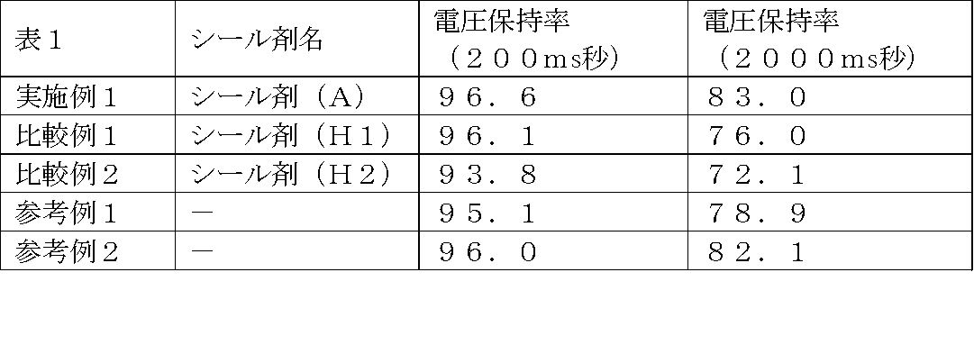
DIC株式会社製のエポキシモノマー「EXA850crp」を70部、ナガセケムテックス社製の1,6-ヘキサンジオールジグリシジルエーテル「デナコールEX-212-L」を30部、信越化学工業株式会社製のシラン系カップリング剤「KBM403」を5部、加えて自転公転式ミキサーTHINKY AR250を用いて均一になるまで混合した。次に、9質量部の担持光カチオン重合開始剤(B)を添加して、3本ロールにて混練し、シール剤(B)とした。この時、カチオン重合性化合物100質量部に対してカチオン重合開始剤は1.1質量部であり分散性微小担体は7.9質量部である。
DIC株式会社製のエポキシモノマー「EXA850crp」を70部、ナガセケムテックス社製の1,6-ヘキサンジオールジグリシジルエーテル「デナコールEX-212-L」を30部、信越化学工業株式会社製のシラン系カップリング剤「KBM403」を5部、加えて自転公転式ミキサーTHINKY AR250を用いて均一になるまで混合した。次に、9質量部の担持熱カチオン重合開始剤(C)を添加して、3本ロールにて混練し、シール剤(C)とした。この時、カチオン重合性化合物100質量部に対してカチオン重合開始剤は0.8質量部であり分散性微小担体は8.2質量部である。
EHC社製のITO付きガラス基板「RZ-B107N1N」1枚に、早川ゴム社製のスペーサ-「LH11S」の5%エタノール分散液を噴霧した。次に、最終的に得られる液晶パネルのシール剤(C)幅が約1mmとなるよう、もう1枚のITO付きガラス基板にシール剤(C)をディスペンサにより塗布した。シール剤(C)は電極を内側にしてこれを取り囲むように矩形状の描画線となるように塗布した。これを120℃で60秒間熱処理した。シール剤(C)の硬化反応が終結する前に、矩形状のシール剤(C)内部にDIC株式会社製の液晶「PA-0211CA033」を適当量滴下し、スペーサを噴霧したガラス基板と対向させて貼り合わせ、液晶パネルを作製した。このパネルを120℃で1時間処理してシール剤(C)の硬化を促進した。
実施例2と同様に電圧保持率を測定し、結果を表2に示した。
DIC株式会社製のエポキシモノマー「EXA850crp」を70部、ナガセケムテックス社製の1,6-ヘキサンジオールジグリシジルエーテル「デナコールEX-212-L」を30部、信越化学工業株式会社製のシラン系カップリング剤「KBM403」を5部、加えて自転公転式ミキサーTHINKY AR250を用いて均一になるまで混合した。次に、9質量部の担持光カチオン重合開始剤(D)を添加して、3本ロールにて混練し、シール剤(D)とした。この時、カチオン重合性化合物100質量部に対してカチオン重合開始剤は1.6質量部であり分散性微小担体は7.4質量部である。
実施例2と同様に電圧保持率を測定し、結果を表2に示した。
DIC株式会社製のエポキシモノマー「EXA850crp」を70部、ナガセケムテックス社製の1,6-ヘキサンジオールジグリシジルエーテル「デナコールEX-212-L」を30部、信越化学工業株式会社製のシラン系カップリング剤「KBM403」を5部、加えて自転公転式ミキサーTHINKY AR250を用いて均一になるまで混合した。次に、9質量部の担持光カチオン重合開始剤(E)を添加して、3本ロールにて混練し、シール剤(E)とした。この時、カチオン重合性化合物100質量部に対してカチオン重合開始剤は5.6質量部であり分散性微小担体は3.4質量部である。
実施例2と同様に電圧保持率を測定し、結果を表2に示した。
DIC株式会社製のエポキシモノマー「EXA850crp」を70部、ナガセケムテックス社製の1,6-ヘキサンジオールジグリシジルエーテル「デナコールEX-212-L」を30部、信越化学工業株式会社製のシラン系カップリング剤「KBM403」を5部、加えて自転公転式ミキサーTHINKY AR250を用いて均一になるまで混合した。次に、9質量部の担持光カチオン重合開始剤(F)を添加して、3本ロールにて混練し、シール剤(F)とした。この時、カチオン重合性化合物100質量部に対してカチオン重合開始剤は0.4質量部であり分散性微小担体は8.6質量部である。
実施例2と同様に電圧保持率を測定し、結果を表2に示した。
DIC株式会社製のエポキシモノマー「EXA850crp」を70部、ナガセケムテックス社製の1,6-ヘキサンジオールジグリシジルエーテル「デナコールEX-212-L」を30部、信越化学工業株式会社製のシラン系カップリング剤「KBM403」を5部、加えて自転公転式ミキサーTHINKY AR250を用いて均一になるまで混合した。次に、9質量部の担持光カチオン重合開始剤(G)を添加して、3本ロールにて混練し、シール剤(G)とした。この時、カチオン重合性化合物100質量部に対してカチオン重合開始剤は0.2質量部であり分散性微小担体は8.8質量部である。
実施例2と同様に電圧保持率を測定し、結果を表2に示した。
DIC株式会社製のエポキシモノマー「EXA850crp」を70部、ナガセケムテックス社製の1,6-ヘキサンジオールジグリシジルエーテル「デナコールEX-212-L」を30部、信越化学工業株式会社製のシラン系カップリング剤「KBM403」を5部、加えて自転公転式ミキサーTHINKY AR250を用いて均一になるまで混合した。次に、9質量部の担持光カチオン重合開始剤(H)を添加して、3本ロールにて混練し、シール剤(H)とした。この時、カチオン重合性化合物100質量部に対してカチオン重合開始剤は0.01質量部であり微小担体は8.8質量部である。
実施例2と同様に電圧保持率を測定し、結果を表2に示した。
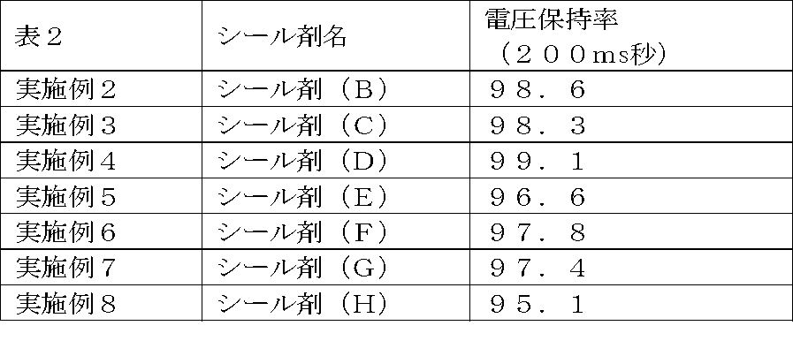
2質量部の担持光カチオン重合開始剤(A)を10質量部のジャパンエポキシレジン株式会社製のエポキシモノマー「エピコート828」、10質量部の「エピコート807」、2.5質量部の三菱化学株式会社「PTMG1000」に添加し、自転公転式ミキサーTHINKY AR250を用いて混合し、シール剤(I)とした。
EHC社製のガラス基板RS-B107M1N(ラビング済みの配向膜付き、ITO付き)を2枚用意し、その一方に早川ゴム社製のスペーサ-「LH11S」の5%エタノール分散液を噴霧した。次にもう1枚のガラス基板に、上記のシール剤(I)を、ディスペンサを用いて、基板の外縁部にシール幅約1mmで矩形状に塗布した。その後、高圧メタハラ灯を使用して500W/m2の紫外線を40秒間、該シール剤部分に照射した。次いでこの基板上の矩形上シール剤の内側に、真空下でDIC株式会社製の液晶「PA-0211CA033」を適当量滴下し、2枚のガラス基板のラビング方向を直交させて貼り合わせセルを作製した。このセルを大気下に戻して基板間の間隔がスペーサのサイズになり、シール剤(I)が遅延硬化するまで1時間放置してTN型の液晶パネルを作製した。
この液晶パネルを2枚の直交する偏光板の間に光学軸を合わせて挟み込み、液晶表示素子を作成した。電圧を印加しない状態で透明に見え明表示となり、電圧を印加するとセルの電極部分が光を通さず暗表示となり、良好な表示状態を示した。
1質量部の光カチオン重合開始剤「SP150」を10質量部のジャパンエポキシレジン株式会社製のエポキシモノマー「エピコート828」、10質量部の「エピコート807」、2.5質量部の三菱化学株式会社「PTMG1000」に添加し、自転公転式ミキサーTHINKY AR250を用いて混合し、シール剤(H3)とした。
シール剤(B)からシール剤(H3)に変更し、それ以外の条件を実施例2と同様にして液晶セルを作製した。即ち、EHC社製のガラス基板RS-B107M1N(ラビング済みの配向膜付き、ITO付き)を2枚用意し、その一方に早川ゴム社製のスペーサ-「LH11S」の5%エタノール分散液を噴霧した。次にもう1枚のガラス基板に、前記シール剤(H3)を、ディスペンサを用いて、基板の外縁部にシール幅約1mmで矩形状に塗布した。その後、高圧メタハラ灯を使用して500W/m2の紫外線を40秒間、該シール剤部分に照射した。次いでこの基板上の矩形上シール剤(H3)の内側に、真空下でDIC株式会社製の液晶「PA-0211CA033」を適当量滴下し、2枚のガラス基板のラビング方向を直交させて貼り合わせセルを作製した。このセルを大気下に戻して基板間の間隔がスペーサのサイズまで圧縮され、その後シール剤(H3)が遅延硬化するまで1時間放置してTN型の液晶パネルを作製した。
実施例9と同様にこれを2枚の直交する偏光板の間に光学軸を合わせて挟み込み、液晶表示素子を作成した。しかしながら、実施例2とは異なり、電圧を印加しない状態でシール剤の周辺部に不透明な部分が現れ、電圧を印加すると電極部分の一部の暗表示が灰色に見えた。
実施例9と比較例3の比較により本発明の方法で作製したシール剤は、液晶汚染性が少ないことが示された。これはシール剤から漏洩して液晶を汚染する光カチオン重合開始剤の量が少ないためと考えられる。
製造例1で得た担持光カチオン重合開始剤(A)1部を、アセトン24部に加えて、超音波洗浄機にて30分振盪し、溶液(B)を作成し、該溶液(B)中に再溶出した光カチオン重合開始剤の量を測定し、「溶出した重合開始剤量」とした。溶出せずに残存した光カチオン重合開始剤量が、シリカに十分な結合力で担持されている重合開始剤量であると評価される。結果を表3に示す。
この結果から、使用する分散性微小担体の種類に関わらず、また担持させる光カチオン重合開始剤の担持量に関わらず、30~60%の光カチオン重合開始剤が溶液(B)に再溶出し、従って70~40%の光カチオン重合開始剤が十分な結合力でシリカに結合していることが示唆された。
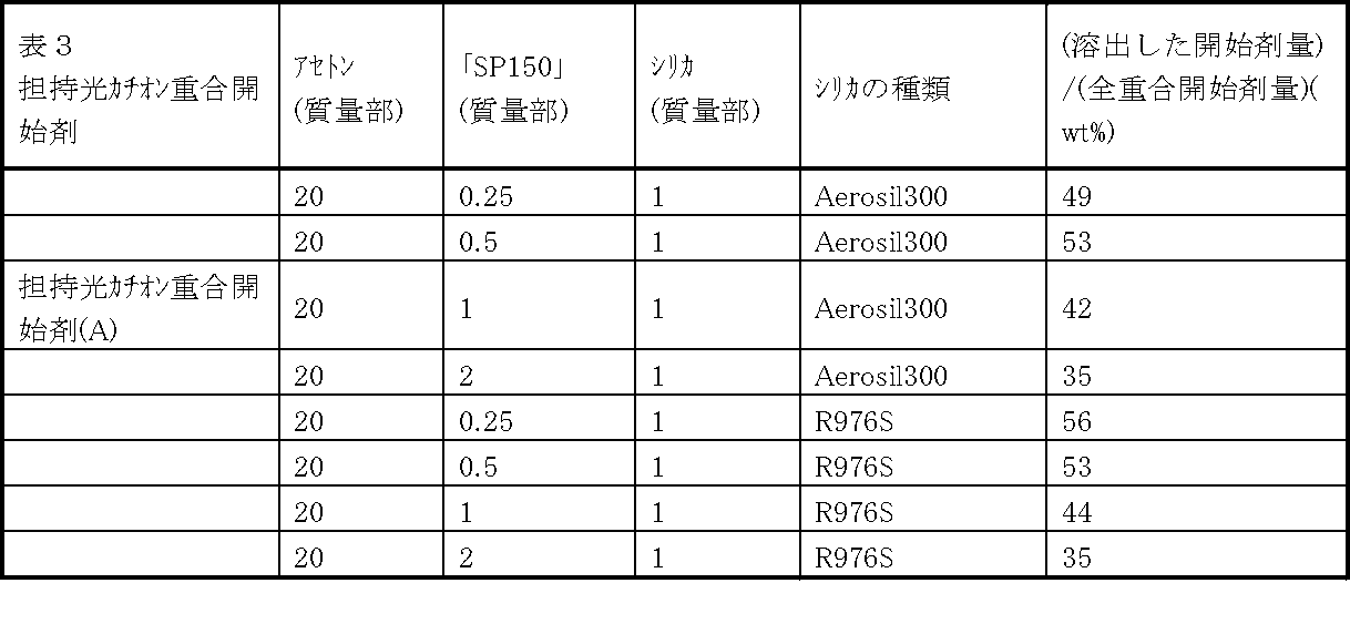
塩基性固体物質(1)は、ヒュームドシリカの表面に塩基性官能基を導入して作製した。ヒュームドシリカとしては日本アエロジル(株)製のR976Sを使用した。以下に作製条件を説明する。各実施例の組成の質量比は表-1にまとめた。
エチルアルコール1800質量部と水200質量部からなる溶液に、シランカップリング剤であるγ-アミノプロピルトリエトキシシラン(LS3150、信越化学工業(株))を溶解した。溶解量は表-1に示した。
ヒュームドシリカ(日本アエロジル(株)製のR976S100質量部を該溶液中に浸漬し、超音波分散装置にて10分間混合した。この溶液を150℃に加熱したホットプレート上で1.5時間加熱処理し粉体を得た。
未反応物及び、またはヒュームドシリカ表面に結合していないシランカップリング剤の重合物を除去するため、この粉体100質量部をエチルアルコール2000質量部に分散し超音波処理装置にて10分間振盪した後、遠心分離して粉体を得た。この洗浄を更に2回繰り返した。この粉体を80℃で4hr熱風乾燥し、塩基性固体物質(1)とした。

実施例4に記載されたシール剤(D)100質量部を用い、これと塩基性固体物質(1)2.5質量部とを自転公転式ミキサーTHINKY AR250を用いて混合し、シール剤(J)を得た。
実施例4に記載されたシール剤(D)100質量部を用い、これと市販のタルク「ミクロライト(竹原化学工業(株)社製)」20質量部とを自転公転式ミキサーTHINKY AR250を用いて混合し、シール剤(K)を得た。
接着剤からの抽出水のpH測定は次のとおり行った。接着剤に紫外線を照射した後、接着剤から外部に滲出する光酸発生剤から生じた酸を定量するため、紫外線を照射した接着剤を超純水中に浸漬し、そのpHを測定した。この測定を行なうため、0.5gの上記接着剤を底面積4.2cm2のガラス製容器に入れ、ガラス製容器の蓋を取って上方より500W/m2の強度の紫外線を20000J/m2照射した。その直後、該ガラス製容器に超純水を5g注ぎ、蓋をして80℃に保った恒温槽に1時間静置した後、室温(23℃)まで冷却しpHを測定した。結果を表5に示す。

実施例10、11のシール剤(J)及び(K)について、電極腐食の促進試験を行った。
前記シール剤(J)及び(K)を、櫛歯電極付セルにアプリケータにて膜厚が10μmになるよう塗布し、紫外線(強度50mW/cm2)を40sec照射して硬化させた。
(櫛歯電極はクロムからなり、電極幅は10μmである。)
櫛歯状の電極は2系統に分かれて対抗しており、互いに櫛歯が入れ子になるように組み合わされ、互いの電極間隔は10μmになっている。電極間に10Vの直流電圧を印加しながら、60℃-90%の環境にて3日間保持し、電極腐食を促進させた後、光学顕微鏡にて電極を観察し、電極腐食の発生しないものには「◎」、僅かな電極腐食の発生したものには「○」、電極腐食の発生したものには「×」とした。結果を表6に示す。

EHC社製のガラス基板RS-B107M1N(ラビング済みの配向膜付き、ITO付き)を2枚用意し、その一方に早川ゴム社製のスペーサ-「LH11S」の5%エタノール分散液を噴霧した。次にもう1枚のガラス基板に、実施例10で作製したシール剤(J)を、ディスペンサを用いて、基板の外縁部にシール幅約1mmで矩形状に塗布し、高圧メタハラ灯を使用して500W/m2の紫外線を40秒間、該シール剤部分に照射した。次いでこの基板上の矩形状シール剤の内側に、真空下でDIC株式会社製の液晶「PA-0211CA033」を適当量滴下し、2枚のガラス基板のラビング方向を直交させて貼り合わせセルを作製した。このセルを大気圧下に戻してTN型の液晶パネルを作製した。
この液晶パネルを2枚の直交する偏光板の間に光学軸を合わせて挟み込み、液晶表示素子を作成した。電圧を印加しない状態で透明に見え明表示となり、電圧を印加するとセルの電極部分が光を通さず暗表示となり、良好な表示状態を示した。
EHC社製のITO付きガラス基板「RZ-B107N1N」1枚に、早川ゴム社製のスペーサ-「LH11S」の5%エタノール分散液を噴霧した。次にもう1枚のITO付きガラス基板に、実施例10、11のシール剤(J)または(K)を、ディスペンサを用いて、基板の外縁部に2箇所の液晶注入口が設けられるように約1mm幅で塗布した後、2枚のガラス基板を対向させて貼り合わせ、窒素雰囲気下、高圧メタルハライドランプを使用して500W/m2の紫外線を40秒間、該シール剤部分に照射し、2穴セルを作製した。2穴セルに真空下でDIC株式会社製の液晶「PA-0211CA033」を注入し、前記液晶組成物が紫外線に直接さらされない様にマスクした後、シール剤(J)または(K)で2穴を封止し、窒素雰囲気下、高圧メタルハライドランプを使用して500W/m2の紫外線を40秒間再照射して、液晶パネルを作製した。
前記の方法で作成した液晶パネルを、60℃90%RH湿熱暴露試験を行い、120時間後の電圧保持率を測定した。電圧保持率は、24℃で液晶パネルに交流5Vの初期電圧を64マイクロ秒印加し、167ミリ秒のフレームタイム前後の電圧比に100を乗じた値を算出した。

Claims (6)
- カチオン重合性化合物と、分散性微小担体に担持された光カチオン重合開始剤及び/又は熱カチオン重合開始剤とを含有することを特徴とするカチオン硬化型液晶シール剤。
- 前記分散性微小担体に担持された光カチオン重合開始剤及び/又は熱カチオン重合開始剤を、前記カチオン重合性化合物に対し1~30質量%含む請求項1に記載のカチオン硬化型液晶シール剤。
- 前記分散性微小担体の表面積が1~5000m2 /gの範囲である請求項1又は2に記載のカチオン硬化型液晶シール剤。
- 前記分散性微小担体に対する前記光カチオン及び/又は熱カチオン重合開始剤の担持量が、1×10-6g/m2~1g/m2の範囲である、請求項1~3のいずれかに記載のカチオン硬化型液晶シール剤。
- 塩基性固体物質を含有する請求項1~4のいずれかに記載のカチオン硬化型液晶シール剤。
- 互いに対向する二つの基板と、前記基板間に設けられたシール剤と、前記シール材に囲まれた封止領域に封入された液晶とを備え、前記シール剤として請求項1~5のいずれかに記載のカチオン硬化型液晶シール剤を使用することを特徴とする液晶表示素子。
Priority Applications (4)
| Application Number | Priority Date | Filing Date | Title |
|---|---|---|---|
| CN201080065897.6A CN102822731B (zh) | 2010-12-13 | 2010-12-13 | 阳离子固化型液晶密封剂以及液晶显示元件 |
| PCT/JP2010/072327 WO2012081067A1 (ja) | 2010-12-13 | 2010-12-13 | カチオン硬化型液晶シール剤、及び液晶表示素子 |
| KR1020127012715A KR101453848B1 (ko) | 2010-12-13 | 2010-12-13 | 양이온 경화형 액정 씰제, 및 액정 표시 소자 |
| JP2011513766A JP4924772B1 (ja) | 2010-12-13 | 2010-12-13 | カチオン硬化型液晶シール剤、及び液晶表示素子 |
Applications Claiming Priority (1)
| Application Number | Priority Date | Filing Date | Title |
|---|---|---|---|
| PCT/JP2010/072327 WO2012081067A1 (ja) | 2010-12-13 | 2010-12-13 | カチオン硬化型液晶シール剤、及び液晶表示素子 |
Publications (1)
| Publication Number | Publication Date |
|---|---|
| WO2012081067A1 true WO2012081067A1 (ja) | 2012-06-21 |
Family
ID=46243843
Family Applications (1)
| Application Number | Title | Priority Date | Filing Date |
|---|---|---|---|
| PCT/JP2010/072327 Ceased WO2012081067A1 (ja) | 2010-12-13 | 2010-12-13 | カチオン硬化型液晶シール剤、及び液晶表示素子 |
Country Status (4)
| Country | Link |
|---|---|
| JP (1) | JP4924772B1 (ja) |
| KR (1) | KR101453848B1 (ja) |
| CN (1) | CN102822731B (ja) |
| WO (1) | WO2012081067A1 (ja) |
Families Citing this family (3)
| Publication number | Priority date | Publication date | Assignee | Title |
|---|---|---|---|---|
| CN104423101A (zh) * | 2013-08-21 | 2015-03-18 | 北京京东方光电科技有限公司 | 一种封框胶涂布装置、方法以及实现对盒的方法 |
| WO2015111525A1 (ja) * | 2014-01-23 | 2015-07-30 | 株式会社ダイセル | 封止用組成物 |
| KR102118365B1 (ko) | 2017-04-21 | 2020-06-04 | 주식회사 엘지화학 | 유기전자소자 봉지용 조성물 |
Citations (5)
| Publication number | Priority date | Publication date | Assignee | Title |
|---|---|---|---|---|
| JP2006317520A (ja) * | 2005-05-10 | 2006-11-24 | Sekisui Chem Co Ltd | 液晶滴下工法用シール剤、液晶滴下工法用遮光性シール剤、上下導通材料及び液晶表示素子 |
| JP2009058665A (ja) * | 2007-08-30 | 2009-03-19 | Sony Corp | 液晶表示装置およびその製造方法 |
| JP2009227969A (ja) * | 2008-02-28 | 2009-10-08 | Sekisui Chem Co Ltd | 光重合開始剤、液晶滴下工法用シール剤、上下導通材料、及び、液晶表示装置 |
| JP2010276671A (ja) * | 2009-05-26 | 2010-12-09 | Sekisui Chem Co Ltd | 液晶表示素子用シール剤、上下導通材料、及び、液晶表示素子 |
| JP2011028254A (ja) * | 2009-06-26 | 2011-02-10 | Dic Corp | カチオン硬化型液晶シール剤、及び液晶表示素子 |
Family Cites Families (9)
| Publication number | Priority date | Publication date | Assignee | Title |
|---|---|---|---|---|
| US4677137A (en) * | 1985-05-31 | 1987-06-30 | Minnesota Mining And Manufacturing Company | Supported photoinitiator |
| JPH0987363A (ja) * | 1995-09-25 | 1997-03-31 | Nippon Zeon Co Ltd | 光硬化性組成物、シール材、シール方法、および液晶封止体 |
| JP2002069160A (ja) * | 1999-12-14 | 2002-03-08 | Mitsui Chemicals Inc | 液晶表示セル用シール剤、液晶表示セルシール剤用組成物及び液晶表示素子 |
| WO2004090621A1 (ja) * | 2003-04-08 | 2004-10-21 | Nippon Kayaku Kabushiki Kaisha | 液晶シール剤およびそれを用いた液晶表示セル |
| JP2005075885A (ja) * | 2003-08-29 | 2005-03-24 | Konica Minolta Medical & Graphic Inc | 光カチオン硬化型樹脂組成物、液晶ディスプレイ用またはエレクトロルミネッセンスディスプレイ用シール材、該シール材を用いる液晶ディスプレイまたはエレクトロルミネッセンスディスプレイ及びシール方法、製造方法 |
| TW200540537A (en) * | 2004-01-20 | 2005-12-16 | Sekisui Chemical Co Ltd | Curable resin composition for liquid crystal displays, sealing material for the liquid crystal dispensing method, transfer materials, and liquid crystal displays |
| JP2010014771A (ja) | 2008-07-01 | 2010-01-21 | Nippon Kayaku Co Ltd | 熱硬化型液晶滴下工法用液晶シール剤及びそれを用いた液晶表示セル |
| JP5253063B2 (ja) * | 2008-09-17 | 2013-07-31 | 協立化学産業株式会社 | 液晶表示装置用シール剤組成物 |
| JP4702502B2 (ja) * | 2009-03-24 | 2011-06-15 | Dic株式会社 | 液晶表示パネルシール用光硬化性組成物及び液晶表示パネル |
-
2010
- 2010-12-13 KR KR1020127012715A patent/KR101453848B1/ko not_active Expired - Fee Related
- 2010-12-13 JP JP2011513766A patent/JP4924772B1/ja not_active Expired - Fee Related
- 2010-12-13 CN CN201080065897.6A patent/CN102822731B/zh not_active Expired - Fee Related
- 2010-12-13 WO PCT/JP2010/072327 patent/WO2012081067A1/ja not_active Ceased
Patent Citations (5)
| Publication number | Priority date | Publication date | Assignee | Title |
|---|---|---|---|---|
| JP2006317520A (ja) * | 2005-05-10 | 2006-11-24 | Sekisui Chem Co Ltd | 液晶滴下工法用シール剤、液晶滴下工法用遮光性シール剤、上下導通材料及び液晶表示素子 |
| JP2009058665A (ja) * | 2007-08-30 | 2009-03-19 | Sony Corp | 液晶表示装置およびその製造方法 |
| JP2009227969A (ja) * | 2008-02-28 | 2009-10-08 | Sekisui Chem Co Ltd | 光重合開始剤、液晶滴下工法用シール剤、上下導通材料、及び、液晶表示装置 |
| JP2010276671A (ja) * | 2009-05-26 | 2010-12-09 | Sekisui Chem Co Ltd | 液晶表示素子用シール剤、上下導通材料、及び、液晶表示素子 |
| JP2011028254A (ja) * | 2009-06-26 | 2011-02-10 | Dic Corp | カチオン硬化型液晶シール剤、及び液晶表示素子 |
Also Published As
| Publication number | Publication date |
|---|---|
| CN102822731A (zh) | 2012-12-12 |
| KR101453848B1 (ko) | 2014-10-22 |
| JP4924772B1 (ja) | 2012-04-25 |
| KR20120096492A (ko) | 2012-08-30 |
| JPWO2012081067A1 (ja) | 2014-05-22 |
| CN102822731B (zh) | 2016-04-20 |
Similar Documents
| Publication | Publication Date | Title |
|---|---|---|
| TWI717470B (zh) | 液晶密封劑及其硬化物以及液晶顯示面板及其製造方法 | |
| WO2013015182A1 (ja) | 液晶シール剤及びそれを用いた液晶表示セル | |
| JP5671825B2 (ja) | カチオン硬化性接着剤、及び液晶表示素子 | |
| JP2004037937A (ja) | 液晶シール剤およびそれを用いた液晶表示セル | |
| JP4924772B1 (ja) | カチオン硬化型液晶シール剤、及び液晶表示素子 | |
| JP4702502B2 (ja) | 液晶表示パネルシール用光硬化性組成物及び液晶表示パネル | |
| CN103649824B (zh) | 液晶密封剂及使用其的液晶显示单元 | |
| JP2011028254A (ja) | カチオン硬化型液晶シール剤、及び液晶表示素子 | |
| CN113661437A (zh) | 液晶滴加工艺用密封剂、使用其的液晶显示面板、及其制造方法 | |
| JP2014006325A (ja) | 液晶シール剤及びそれを用いた液晶表示セル | |
| JP6249946B2 (ja) | 液晶シール剤及びそれを用いた液晶表示セル | |
| JP5828314B2 (ja) | 液晶配向剤 | |
| JP5109324B2 (ja) | シール剤用光硬化性組成物、液晶シール剤、及び液晶パネル | |
| TWI879899B (zh) | 液晶滴下工法用密封劑及液晶顯示面板的製造方法 | |
| TWI882101B (zh) | 液晶滴下工法用密封劑及液晶顯示面板的製造方法、以及液晶顯示面板 | |
| JP2004339341A (ja) | シール剤組成物 | |
| JP2011118105A (ja) | カチオン光硬化型液晶パネルシール剤及びそれを用いた液晶パネルの製造方法 | |
| JP2014006324A (ja) | 液晶シール剤及びそれを用いた液晶表示セル |
Legal Events
| Date | Code | Title | Description |
|---|---|---|---|
| WWE | Wipo information: entry into national phase |
Ref document number: 201080065897.6 Country of ref document: CN |
|
| WWE | Wipo information: entry into national phase |
Ref document number: 2011513766 Country of ref document: JP |
|
| ENP | Entry into the national phase |
Ref document number: 20127012715 Country of ref document: KR Kind code of ref document: A |
|
| 121 | Ep: the epo has been informed by wipo that ep was designated in this application |
Ref document number: 10860662 Country of ref document: EP Kind code of ref document: A1 |
|
| NENP | Non-entry into the national phase |
Ref country code: DE |
|
| 122 | Ep: pct application non-entry in european phase |
Ref document number: 10860662 Country of ref document: EP Kind code of ref document: A1 |