WO2012073755A1 - 可撓性マグネット、可撓性マグネットの製造方法、磁気エンコーダ、アクチュエータ - Google Patents
可撓性マグネット、可撓性マグネットの製造方法、磁気エンコーダ、アクチュエータ Download PDFInfo
- Publication number
- WO2012073755A1 WO2012073755A1 PCT/JP2011/076891 JP2011076891W WO2012073755A1 WO 2012073755 A1 WO2012073755 A1 WO 2012073755A1 JP 2011076891 W JP2011076891 W JP 2011076891W WO 2012073755 A1 WO2012073755 A1 WO 2012073755A1
- Authority
- WO
- WIPO (PCT)
- Prior art keywords
- sheet
- magnet
- magnetic
- flexible magnet
- flexible
- Prior art date
Links
Images

Classifications
-
- H—ELECTRICITY
- H02—GENERATION; CONVERSION OR DISTRIBUTION OF ELECTRIC POWER
- H02K—DYNAMO-ELECTRIC MACHINES
- H02K41/00—Propulsion systems in which a rigid body is moved along a path due to dynamo-electric interaction between the body and a magnetic field travelling along the path
- H02K41/02—Linear motors; Sectional motors
- H02K41/03—Synchronous motors; Motors moving step by step; Reluctance motors
- H02K41/031—Synchronous motors; Motors moving step by step; Reluctance motors of the permanent magnet type
-
- G—PHYSICS
- G01—MEASURING; TESTING
- G01D—MEASURING NOT SPECIALLY ADAPTED FOR A SPECIFIC VARIABLE; ARRANGEMENTS FOR MEASURING TWO OR MORE VARIABLES NOT COVERED IN A SINGLE OTHER SUBCLASS; TARIFF METERING APPARATUS; MEASURING OR TESTING NOT OTHERWISE PROVIDED FOR
- G01D5/00—Mechanical means for transferring the output of a sensing member; Means for converting the output of a sensing member to another variable where the form or nature of the sensing member does not constrain the means for converting; Transducers not specially adapted for a specific variable
- G01D5/12—Mechanical means for transferring the output of a sensing member; Means for converting the output of a sensing member to another variable where the form or nature of the sensing member does not constrain the means for converting; Transducers not specially adapted for a specific variable using electric or magnetic means
- G01D5/14—Mechanical means for transferring the output of a sensing member; Means for converting the output of a sensing member to another variable where the form or nature of the sensing member does not constrain the means for converting; Transducers not specially adapted for a specific variable using electric or magnetic means influencing the magnitude of a current or voltage
- G01D5/142—Mechanical means for transferring the output of a sensing member; Means for converting the output of a sensing member to another variable where the form or nature of the sensing member does not constrain the means for converting; Transducers not specially adapted for a specific variable using electric or magnetic means influencing the magnitude of a current or voltage using Hall-effect devices
- G01D5/145—Mechanical means for transferring the output of a sensing member; Means for converting the output of a sensing member to another variable where the form or nature of the sensing member does not constrain the means for converting; Transducers not specially adapted for a specific variable using electric or magnetic means influencing the magnitude of a current or voltage using Hall-effect devices influenced by the relative movement between the Hall device and magnetic fields
-
- H—ELECTRICITY
- H01—ELECTRIC ELEMENTS
- H01F—MAGNETS; INDUCTANCES; TRANSFORMERS; SELECTION OF MATERIALS FOR THEIR MAGNETIC PROPERTIES
- H01F1/00—Magnets or magnetic bodies characterised by the magnetic materials therefor; Selection of materials for their magnetic properties
- H01F1/01—Magnets or magnetic bodies characterised by the magnetic materials therefor; Selection of materials for their magnetic properties of inorganic materials
- H01F1/03—Magnets or magnetic bodies characterised by the magnetic materials therefor; Selection of materials for their magnetic properties of inorganic materials characterised by their coercivity
- H01F1/032—Magnets or magnetic bodies characterised by the magnetic materials therefor; Selection of materials for their magnetic properties of inorganic materials characterised by their coercivity of hard-magnetic materials
- H01F1/04—Magnets or magnetic bodies characterised by the magnetic materials therefor; Selection of materials for their magnetic properties of inorganic materials characterised by their coercivity of hard-magnetic materials metals or alloys
- H01F1/06—Magnets or magnetic bodies characterised by the magnetic materials therefor; Selection of materials for their magnetic properties of inorganic materials characterised by their coercivity of hard-magnetic materials metals or alloys in the form of particles, e.g. powder
- H01F1/08—Magnets or magnetic bodies characterised by the magnetic materials therefor; Selection of materials for their magnetic properties of inorganic materials characterised by their coercivity of hard-magnetic materials metals or alloys in the form of particles, e.g. powder pressed, sintered, or bound together
- H01F1/083—Magnets or magnetic bodies characterised by the magnetic materials therefor; Selection of materials for their magnetic properties of inorganic materials characterised by their coercivity of hard-magnetic materials metals or alloys in the form of particles, e.g. powder pressed, sintered, or bound together in a bonding agent
-
- H—ELECTRICITY
- H01—ELECTRIC ELEMENTS
- H01F—MAGNETS; INDUCTANCES; TRANSFORMERS; SELECTION OF MATERIALS FOR THEIR MAGNETIC PROPERTIES
- H01F7/00—Magnets
- H01F7/02—Permanent magnets [PM]
- H01F7/0205—Magnetic circuits with PM in general
- H01F7/021—Construction of PM
- H01F7/0215—Flexible forms, sheets
-
- F—MECHANICAL ENGINEERING; LIGHTING; HEATING; WEAPONS; BLASTING
- F16—ENGINEERING ELEMENTS AND UNITS; GENERAL MEASURES FOR PRODUCING AND MAINTAINING EFFECTIVE FUNCTIONING OF MACHINES OR INSTALLATIONS; THERMAL INSULATION IN GENERAL
- F16C—SHAFTS; FLEXIBLE SHAFTS; ELEMENTS OR CRANKSHAFT MECHANISMS; ROTARY BODIES OTHER THAN GEARING ELEMENTS; BEARINGS
- F16C29/00—Bearings for parts moving only linearly
- F16C29/04—Ball or roller bearings
- F16C29/06—Ball or roller bearings in which the rolling bodies circulate partly without carrying load
- F16C29/0633—Ball or roller bearings in which the rolling bodies circulate partly without carrying load with a bearing body defining a U-shaped carriage, i.e. surrounding a guide rail or track on three sides
- F16C29/0635—Ball or roller bearings in which the rolling bodies circulate partly without carrying load with a bearing body defining a U-shaped carriage, i.e. surrounding a guide rail or track on three sides whereby the return paths are provided as bores in a main body of the U-shaped carriage, e.g. the main body of the U-shaped carriage is a single part with end caps provided at each end
- F16C29/0638—Ball or roller bearings in which the rolling bodies circulate partly without carrying load with a bearing body defining a U-shaped carriage, i.e. surrounding a guide rail or track on three sides whereby the return paths are provided as bores in a main body of the U-shaped carriage, e.g. the main body of the U-shaped carriage is a single part with end caps provided at each end with balls
- F16C29/0642—Ball or roller bearings in which the rolling bodies circulate partly without carrying load with a bearing body defining a U-shaped carriage, i.e. surrounding a guide rail or track on three sides whereby the return paths are provided as bores in a main body of the U-shaped carriage, e.g. the main body of the U-shaped carriage is a single part with end caps provided at each end with balls with four rows of balls
-
- G—PHYSICS
- G01—MEASURING; TESTING
- G01D—MEASURING NOT SPECIALLY ADAPTED FOR A SPECIFIC VARIABLE; ARRANGEMENTS FOR MEASURING TWO OR MORE VARIABLES NOT COVERED IN A SINGLE OTHER SUBCLASS; TARIFF METERING APPARATUS; MEASURING OR TESTING NOT OTHERWISE PROVIDED FOR
- G01D2205/00—Indexing scheme relating to details of means for transferring or converting the output of a sensing member
- G01D2205/80—Manufacturing details of magnetic targets for magnetic encoders
-
- H—ELECTRICITY
- H02—GENERATION; CONVERSION OR DISTRIBUTION OF ELECTRIC POWER
- H02K—DYNAMO-ELECTRIC MACHINES
- H02K1/00—Details of the magnetic circuit
- H02K1/02—Details of the magnetic circuit characterised by the magnetic material
-
- H—ELECTRICITY
- H02—GENERATION; CONVERSION OR DISTRIBUTION OF ELECTRIC POWER
- H02K—DYNAMO-ELECTRIC MACHINES
- H02K7/00—Arrangements for handling mechanical energy structurally associated with dynamo-electric machines, e.g. structural association with mechanical driving motors or auxiliary dynamo-electric machines
- H02K7/08—Structural association with bearings
Definitions
- the present invention relates to a flexible magnet, a method of manufacturing a flexible magnet, a magnetic encoder, and an actuator.
- a linear magnetic scale in which N poles and S poles are alternately magnetized on the surface of a belt-like magnetic material member is known.
- This linear magnetic scale is used as a part of a linear magnetic encoder.
- a relative position between the magnetic scale and the magnetic sensor is detected by arranging a magnetic sensor such as an MR sensor so as to be opposed to the linear magnetic scale.
- the linear magnetic encoder is used for detecting the position of a movable part of a linear motor.
- Linear magnetic encoders are required to be less susceptible to external magnetic fields.
- the magnetic output from the linear magnetic scale is required to be large and stable. For this reason, a magnet having a strong magnetic force such as a neodymium magnet is used for the linear magnetic scale.
- the linear magnetic scale may be required to be bendable in order to be used for measuring a curved portion.
- a flexible magnet called a bond magnet is used. Bonded magnets are magnets that are crushed and kneaded into rubber or plastic.
- the bond magnet is also called a rubber magnet, a vinyl chloride magnet, or a plastic magnet.
- bond magnets in which neodymium magnets are kneaded into rubber or the like have the property of being brittle. For this reason, what adhered the metal plate, such as a stainless steel plate, to the back side of the sheet-like bond magnet containing a neodymium magnet etc. is used (refer patent document 1).
- An object of the present invention is to provide a flexible magnet having a strong magnetic force and rich in flexibility, a method for manufacturing the flexible magnet, a magnetic encoder, and an actuator.
- the flexible magnet according to the present invention is formed by containing a rare earth magnetic powder in a resin, and by forming a first sheet having N and S poles magnetized on the surface, and a ferrite magnetic powder in the resin. And a second sheet fixed to the back surface of the first sheet.
- the method for producing a flexible magnet according to the present invention includes a step of forming a first sheet by containing rare earth magnetic powder in a resin, a step of forming a second sheet by adding ferrite magnetic powder to the resin, The method includes: a step of superimposing and fixing the first sheet and the second sheet; and a step of magnetizing an N pole and an S pole on the surface of the first sheet.
- a magnetic encoder includes a magnetic scale having N and S poles magnetized on a surface thereof, and a magnetic sensor arranged to face the magnetic scale.
- a flexible magnet or a flexible magnet manufactured by the method of manufacturing a flexible magnet is used.
- An actuator includes a magnet portion having a north pole and a south pole magnetized on a surface, and a coil portion in which a plurality of coils are arranged to face the magnet portion, and the magnetic field of the magnet portion and the coil
- the flexible magnet manufactured by the flexible magnet or the manufacturing method of the flexible magnet is used as the magnet portion.
- the second sheet functions as a reinforcing member for the first sheet. Therefore, even when the flexible magnet is bent or twisted.
- the first sheet will not crack or tear.
- the flexible magnet since the flexible magnet has the first sheet having a high strength magnetic force, it can be suitably used for a magnetic scale or the like.
- a flexible magnet can be attached in close contact with the curved part etc. according to the shape.
- the first sheet generates a strong magnetic force, so that the magnetic encoder can improve detection accuracy and can be stabilized. Therefore, the actuator can obtain a high driving force.
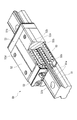
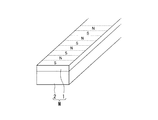
- FIG. 1 is a perspective view showing a schematic configuration of an actuator A (linear motor 5) according to an embodiment of the present invention.
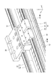
- FIG. 2 is an enlarged perspective view (partially sectional view) showing the base 10 and the table 20.
- FIG. 3 is a cross-sectional view showing a schematic configuration of the linear motor 5.
- the actuator A includes a linear motor 5, a motor driver 80 (control device) that controls the linear motor 5, and a user terminal 90 (information processing device) connected to the motor driver 80.
- the linear motor 5 includes a base 10 that is elongated in a uniaxial direction (X direction), and a table 20 that is slidable with respect to the base 10.
- a pair of linear guides 50 is provided between the base 10 and the table 20.
- the table 20 can slide smoothly with respect to the base 10.
- the position / velocity / acceleration of the table 20 with respect to the base 10 is detected by the linear magnetic encoder 60 (see FIG. 3).
- the linear magnetic encoder 60 has a resolution of about 1 ⁇ m, for example.
- the linear magnetic encoder 60 includes a magnetic scale 61 attached to the base 10 and a magnetic sensor 62 attached to the table 20.
- the magnetic scale 61 is made of an elongated rectangular magnetic material.
- the magnetic scale 61 is formed by magnetizing N poles and S poles alternately at a constant pitch (for example, 2 mm) on the upper surface thereof.
- the magnetic scale 61 is disposed in close contact with the outer surface of the side wall 12 of the base 10 along the longitudinal direction (X direction) of the base 10.
- a flexible magnet M is used for the magnetic scale 61 (see FIGS. 6A and 6B).
- the flexible magnet M is a bonded magnet formed in a two-layer structure of a first sheet 1 having a strong magnetic force and a second sheet 2 having a weak magnetic force welded to the back surface 1b of the first sheet 1.
- seat 1 magnetizes the surface (upper surface) so that a north pole and a south pole may follow a longitudinal direction by a fixed pitch alternately.
- the flexible magnet M is fixed along the longitudinal direction (X direction) of the base 10.
- the second sheet 2 on the back surface side is closely fixed to the outer surface side of the side wall portion 12 of the base 10 via a double-sided tape or an adhesive.
- the first sheet 1 exposed on the front side functions as the magnetic scale 61. The detailed configuration of the flexible magnet M will be described later.
- the magnetic sensor 62 detects the magnetism of the magnetic scale 61 with an MR element.
- the magnetic sensor 62 outputs a sine wave signal by relatively moving along the magnetic scale 61.
- the signal detected by the magnetic sensor 62 is sent to the motor driver 80 via a signal processing unit (not shown).
- the motor driver 80 controls the current supplied to the coil unit 40 so that the table 20 moves to the command position. In this way, the linear motor 5 is controlled.
- the control method of the linear motor 5 is feedback control or the like.
- the position information, speed information, and acceleration information of the table 20 measured using the magnetic sensor 62 are sent to the motor driver 80, the difference from the target value (command value) is calculated, the position of the table 20,
- the three-phase alternating current for the three coils 41 of the coil unit 40 is controlled so that the speed and acceleration approach the target values.
- the base 10 is formed of an elongated rectangular bottom wall portion 11 and a pair of side wall portions 12 provided perpendicular to both ends in the width direction (Y direction) of the bottom wall portion 11.
- the base 10 is made of a magnetic material such as steel or a non-magnetic material such as aluminum.
- a magnet portion 30 in which a plurality of magnets are arranged is attached to the upper surface of the bottom wall portion 11 of the base 10.
- Track rails 51 of the linear guide 50 are arranged along the uniaxial direction on the upper surfaces of the side wall portions 12 of the base 10.
- the two track rails 51 are arranged in parallel.
- Two moving blocks 52 are attached to each track rail 51.
- the table 20 is made of a nonmagnetic material such as aluminum and is formed in a rectangular plate shape.
- the moving blocks 52 of the linear guide 50 are attached to the four corners of the lower surface 20b of the table 20.
- the four moving blocks 52 are attached to the two track rails 51 described above.
- the table 20 is supported by the base 10 by a pair of linear guides 50 so as to be linearly movable.
- a coil portion 40 including three coils 41 and the like is fixed so as to be suspended between the four moving blocks 52 (center portion).
- the three coils 41 function as a three-phase coil (armature).
- a gap g is set between the magnet part 30 attached to the base 10 and the coil part 40 attached to the table 20. The gap g is kept constant even when the table 20 moves linearly with respect to the base 10 by the pair of linear guides 50.
- the magnet unit 30 generates a magnetic field toward the coil unit 40.
- the magnet unit 30 is a magnet formed in an elongated rectangular plate shape.
- the magnet portion 30 is obtained by magnetizing the N pole and the S pole alternately along the longitudinal direction (X direction) of the base 10 at a constant pitch on the surface (upper surface).
- a flexible magnet M is used for the magnet unit 30 (see FIGS. 6A and 6B).
- the flexible magnet M used for the magnet unit 30 has the same configuration as the flexible magnet M used for the magnetic scale 61.
- the shape dimension, magnetic force, magnetization pitch, and the like of the flexible magnet M are optimized according to the required specifications of the magnet unit 30.
- the flexible magnet M is fixed along the longitudinal direction (X direction) of the base 10.
- the second sheet 2 on the back surface side is tightly fixed to the bottom wall portion 11 of the base 10 via a double-sided tape or an adhesive.
- the first sheet 1 exposed on the front side generates a magnetic field toward the coil unit 40.
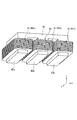
- FIG. 4 is a perspective view showing the coil unit 40.
- a three-phase coil (armature) is attached to the center of the lower surface of the table 20.
- the three-phase coil is a coil unit 40 including three coils 41 and a core 42.
- the material of the core 42 is a magnetic material such as silicon steel.
- the core 42 has three comb teeth 42a, 42b, and 42c that strengthen the magnetic field generated in the three-phase coil (coil 41).
- the three coils 41 are wound around the three comb teeth 42a, 42b, and 42c of the core 42, respectively.
- the three coils 41 are arranged along the moving direction of the table 20.
- the coil 41 wound around the comb teeth 42a is a U-phase coil 41a.
- the coil 41 wound around the comb teeth 42b is a V-phase coil 41b.
- the coil 41 wound around the comb teeth 42c is a W-phase coil 41c.
- a three-phase alternating current having a phase difference of 120 degrees is passed through the three coils 41.
- a traveling magnetic field is generated from the coil unit 40. Thrust is generated in the coil unit 40 (table 20) by the action of the traveling magnetic field generated in the coil unit 40 and the magnetic field generated in the magnet unit 30.
- the current flowing through the three coils 41 of the coil unit 40 is controlled by the motor driver 80.
- FIG. 5 shows a perspective view of the linear guide 50.
- the linear guide 50 has a track rail 51 attached to the upper surface of the side wall portion 12 of the base 10.
- a plurality of mounting holes 51b are formed in the track rail 51 at a predetermined pitch in the longitudinal direction.
- the track rail 51 is fixed to the side wall portion 12 by passing a bolt through the mounting hole 51 b and screwing the bolt into the screw hole of the side wall portion 12 of the base 10.
- a plurality of ball rolling grooves 51a in which the balls 55 roll along the longitudinal direction are formed on the track rail 51.
- the cross-sectional shape of the ball rolling groove 51a is a circular arc groove shape made of a single arc slightly larger than the radius of the ball 55, or a Gothic arch groove shape made of two arcs.
- the ball rolling groove 51 a is formed not only on the side surface of the track rail 51 but also on the upper surface of the track rail 51. By forming the ball rolling groove 51 a on the upper surface of the track rail 51, the vertical rigidity of the linear guide 50 can be increased.
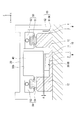
- the moving block 52 is formed in a bowl shape straddling the track rail 51.
- a load ball rolling groove 52a facing the ball rolling groove 51a of the track rail 51 is formed, and a ball circulation path including the load ball rolling groove 52a is formed.
- An end plate 53 is attached to each end surface of the moving block 52 in one axial direction.
- the ball circulation path includes a load ball rolling groove 52 a, a ball return path 52 b extending in parallel with the load ball rolling groove 52 a, and a direction changing path 52 c formed in the end plate 53.
- the direction changing path 52c is formed in a U shape that connects the end of the loaded ball rolling groove 52a and the end of the ball return path 52b.
- the entire ball circulation path is formed in a circuit shape.
- a plurality of balls 55 are arranged and accommodated in the ball circulation path.
- a mounting screw 52d for mounting the table 20 is processed on the moving block 52.
- the moving block 52 is screwed to the lower surface 20 b of the table 20
- the ball 55 rolled to one end of the loaded ball rolling groove 52a is guided to the direction changing path 52c. Further, the ball 55 is returned to the other end of the loaded ball rolling groove 52a after passing through the ball return path 52b and the opposite direction changing path 52c.
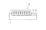
- FIG. 6 is a perspective view and a sectional view showing the configuration of the flexible magnet M according to the embodiment of the present invention.
- the flexible magnet M is a sheet-like bond magnet formed in an elongated rectangular plate shape.
- the flexible magnet M includes a first sheet 1 having a strong magnetic force and a second sheet 2 having a weak magnetic force welded to the back surface 1b of the first sheet 1.
- the flexible magnet M is a bonded magnet formed in a two-layer structure of a first sheet 1 and a second sheet 2.
- the first sheet 1 is formed with, for example, a short side direction of 10 mm, a long side direction of 1 m, and a thickness of 1 mm.
- the surface 1a of the first sheet 1 is alternately magnetized with N and S poles at a pitch of 2 mm, for example, along the longitudinal direction.
- the first sheet 1 is formed in an elongated rectangular plate shape by kneading rare earth magnetic powder into a binder resin such as vulcanized rubber or elastomer.
- a powder of neodymium, samarium-cobalt or samarium-iron nitride is used as the rare earth magnetic powder.
- the first sheet 1 generates a high strength magnetic force.
- the second sheet 2 is formed in the same shape as the first sheet 1.
- the second sheet 2 is formed with, for example, a short direction of 10 mm and a long direction of 1 m.
- the second sheet 2 is formed thicker than the first sheet 1.
- the thickness of the second sheet 2 is 3 mm.
- the second sheet 2 is formed in an elongated rectangular plate shape by kneading ferrite magnetic powder into a binder resin such as vulcanized rubber or elastomer.
- ferrite-based magnetic powder powders of manganese zinc ferrite, nickel zinc ferrite, copper zinc ferrite and the like are used.
- the second sheet 2 generates a weak magnetic force as compared with the first sheet 1.
- the flexible magnet M is manufactured through the following steps. First, the first sheet 1 and the second sheet 2 are formed separately. Magnetic powder is kneaded into a binder resin such as vulcanized rubber to form an elongated rectangular plate. At this time, the binder resin used for the first sheet 1 and the second sheet 2 is preferably the same. This is because the hardness, flexibility, and flexibility of the first sheet 1 and the second sheet 2 are matched.
- the content of magnetic powder (neodymium, ferrite, etc.) with respect to the binder resin can be arbitrarily set. For example, a sufficient magnetic force can be obtained by containing 80 percent or more of magnetic powder.
- first sheet 1 and the second sheet 2 are superposed and then heated to weld the first sheet 1 and the second sheet 2 together.
- the first sheet 1 and the second sheet 2 are welded using a press molding machine.
- a flexible magnet M having a thickness of 4 mm is obtained.
- N poles and S poles are alternately magnetized on the surface 1 a of the first sheet 1.
- the arrangement pitch of the N pole and the S pole can be arbitrarily set.
- the flexible magnet M is used for a magnetic scale, it is magnetized at a pitch of 2 mm, for example.
- the flexible magnet M is used for the magnet portion of the linear motor, it is magnetized at a pitch of several mm to several tens mm, for example.
- the first sheet 2 may be magnetized at the same time.
- the flexible magnet M includes a first sheet 1 having a high strength magnetic force. Therefore, it can be suitably used for the magnet unit 30 and the magnetic scale 61.
- the first sheet 1 contains magnetic powder such as neodymium, it has the property of being brittle.
- the flexible magnet M since the flexible magnet M has the second sheet 2 overlapped and welded to the first sheet 1, the first sheet 1 can be used even when the flexible magnet M is bent or twisted. Does not crack or tear.
- the second sheet 2 functions as a reinforcing member for the first sheet 1.
- the second sheet 2 also functions as a back yoke for the first sheet 1.
- the second sheet 2 functions as a yoke that concentrates the magnetic lines of force from the first sheet 1. Therefore, the first sheet 1 generates a strong and stable magnetic force from the surface 1a.
- the flexibility and flexibility of the flexible magnet M are inherent to the bonded magnet.
- a metal plate is used as the reinforcing member.
- the flexible magnet M has higher flexibility and flexibility. Accordingly, the flexible magnet M can be attached in close contact with a curved portion or the like following its shape.
- the flexible magnet M can be suitably used for the magnet unit 30 of the linear motor 5, the magnetic scale 61 of the linear magnetic encoder 60, and the like.
- the linear motor 5 can obtain a high driving force.
- the linear magnetic encoder 60 magnetic scale 61
- the linear magnetic encoder 60 can improve detection accuracy and can be stabilized.
- the present invention is not limited thereto.
- An arbitrary magnetic pattern may be formed on the surface of the first sheet 1.
- the case where the N pole and the S pole are alternately magnetized on the surface of the first sheet 1 along an arbitrary curve may be used.
- the surface of the first sheet 1 may be alternately magnetized with N and S poles along two directions.
- the flexible magnet M is used, for example, for a magnet portion of a planar motor or a magnetic scale of a magnetic encoder that performs position detection in two directions.
- the N pole and S pole magnetized on the surface of the first sheet 1 are not limited to a constant pitch, and may be at an arbitrary interval.
- the present invention is not limited thereto.
- the magnet part 30 and the magnetic scale 61 may be curved or bent.
- the rolling elements of the linear guide 50 are not limited to a plurality of balls 55.
- the rolling element may be a roller or the like.
- a sliding guide mechanism may be used instead of the linear guide 50.
- the second sheet 2 thicker than the first sheet 1. This is because if the thickness of the second sheet 2 is too thin, the magnetic flux (line of magnetic force) emitted from the first sheet 1 passes through the second sheet 2 and becomes a leakage magnetic flux to the outside.
- the second sheet 2 (ferrite) has a lower saturation magnetic flux density than the first sheet 1 (neodymium etc.). For this reason, in order not to leak the magnetic flux from the first sheet 1 to the outside, it is necessary to increase the magnetic flux that can pass through the inside of the second sheet 2 by making the second sheet 2 thicker than the first sheet 1.
- the present invention is not limited to this.
- a magnetic material such as steel
- the magnetism of the flexible magnet M (second sheet 2) itself is used without using a fastening member such as a bolt or an adhesive.
- the magnetic material may be tightly fixed.
- the attachment position of the flexible magnet M and the replacement of the flexible magnet M can be easily performed. Therefore, the flexible magnet M (magnet part 30, magnetic scale 61) is excellent in maintainability.
- M flexible magnet, 1 ... first sheet, 1b ... back surface, 2 ... second sheet, A ... actuator, 5 ... linear motor, 30 ... magnet section, 60 ... linear magnetic encoder, 61 ... magnetic scale, 62 ... Magnetic sensor
Landscapes
- Engineering & Computer Science (AREA)
- Physics & Mathematics (AREA)
- Power Engineering (AREA)
- Electromagnetism (AREA)
- Chemical & Material Sciences (AREA)
- Combustion & Propulsion (AREA)
- General Physics & Mathematics (AREA)
- Linear Motors (AREA)
- Transmission And Conversion Of Sensor Element Output (AREA)
- Measurement Of Length, Angles, Or The Like Using Electric Or Magnetic Means (AREA)
- Manufacturing Cores, Coils, And Magnets (AREA)
Abstract
可撓性マグネット(M)は、希土類磁性粉末を樹脂に含有させて形成すると共に表面にN極とS極を着磁した第一シート(1)と、フェライト系磁性粉末を樹脂に含有させて形成すると共に前記第一シート(1)の裏面に固着された第二シート(2)と、を有する。
Description
本発明は、可撓性マグネット、可撓性マグネットの製造方法、磁気エンコーダ、アクチュエータに関する。
本願は、2010年11月30日に日本に出願された特願2010-267426号に基づき優先権を主張し、その内容をここに援用する。
本願は、2010年11月30日に日本に出願された特願2010-267426号に基づき優先権を主張し、その内容をここに援用する。
帯状の磁性体部材の表面に、N極とS極を交互に着磁したリニア磁気スケールが知られている。このリニア磁気スケールは、リニア磁気エンコーダの一部に用いられる。リニア磁気スケールに対してMRセンサ等の磁気センサを対向配置して相対移動させることにより、磁気スケールと磁気センサの相対位置を検出する。リニア磁気エンコーダは、リニアモータの可動部の位置等を検出に用いられる。
リニア磁気エンコーダは、外部磁界の影響を受けにくいことが要請される。リニア磁気スケールからの磁気出力が大きく安定していることが要請される。このため、リニア磁気スケールには、ネオジム磁石等の強い磁力を有する磁石が用いられる。
リニア磁気スケールは、曲線部分の計測等に用いるために、湾曲可能であることも要請される場合もある。このため、ボンド磁石と呼ばれる、柔軟性のある磁石が用いられる。ボンド磁石は、磁石を砕いてゴムやプラスチックに練り込んだものである。ボンド磁石は、ゴム磁石、塩ビ磁石又はプラスチック磁石などとも呼ばれる。
ところが、ネオジム磁石等をゴム等に練り込んだボンド磁石は、脆いという性質がある。このため、ネオジム磁石等を含むシート状のボンド磁石の裏面側に補強部材としてステンレス板等の金属板を貼り付けたものが用いられている(特許文献1参照)。
ネオジム磁石等を含むシート状のボンド磁石の裏面側に金属板等の補強部材を貼り付けると、ボンド磁石本来の柔軟性・可撓性が損なわれてしまう。また、重量化、錆つき、温度変形、高コスト化等の問題が発生する。
本発明は、強い磁力を有すると共に柔軟性に富む可撓性マグネット、可撓性マグネットの製造方法、磁気エンコーダ、アクチュエータを提供することを目的とする。
本発明に係る可撓性マグネットは、希土類磁性粉末を樹脂に含有させて形成すると共に表面にN極とS極を着磁した第一シートと、フェライト系磁性粉末を樹脂に含有させて形成すると共に前記第一シートの裏面に固着された第二シートと、を有することを特徴とする。
本発明に係る可撓性マグネットの製造方法は、希土類磁性粉末を樹脂に含有させて第一シートを形成する工程と、フェライト系磁性粉末を樹脂に含有させて第二シートを形成する工程と、前記第一シート及び前記第二シートを重ね合わせて固着する工程と、前記第一シートの表面にN極とS極を着磁する工程と、を有することを特徴とする。
本発明に係る磁気エンコーダは、表面にN極とS極を着磁した磁気スケールと、前記磁気スケールに対して対向配置される磁気センサと、を備える磁気エンコーダにおいて、前記磁気スケールとして、上記可撓性マグネット若しくは上記可撓性マグネットの製造方法により製造された可撓性マグネットを用いることを特徴とする。
本発明に係るアクチュエータは、表面にN極とS極を着磁した磁石部と、複数のコイルを前記磁石部に対向して配列したコイル部と、を備え、前記磁石部の磁界と前記コイルに流れる電流とにより前記磁石部と前記コイル部と相対移動させるアクチュエータにおいて、前記磁石部として、上記可撓性マグネット若しくは上記可撓性マグネットの製造方法により製造された可撓性マグネットを用いることを特徴とする。
本発明に係る可撓性マグネット及び可撓性マグネットの製造方法によれば、第二シートが第一シートの補強部材として機能するので、可撓性マグネットを曲げたり捻ったりした場合であっても、第一シートが割れたり裂けたりしない。
また、可撓性マグネットは、高強度の磁力を有する第一シートを有するので、磁気スケール等に好適に用いることができる。また、高い柔軟性・可撓性を有するので、可撓性マグネットを湾曲した部位等にその形状に倣って密着して取り付けることができる。
また、可撓性マグネットは、高強度の磁力を有する第一シートを有するので、磁気スケール等に好適に用いることができる。また、高い柔軟性・可撓性を有するので、可撓性マグネットを湾曲した部位等にその形状に倣って密着して取り付けることができる。
本発明に係る磁気エンコーダ、アクチュエータによれば、第一シートが強い磁力を発生するので、磁気エンコーダは検出精度の向上や安定化を図ることができる。したがって、アクチュエータは高い推進力を得ることができる。
図1は、本発明の実施形態に係るアクチュエータA(リニアモータ5)の概略構成を示す斜視図である。図2は、ベース10及びテーブル20を示す拡大斜視図(一部断面図)である。図3は、リニアモータ5の概略構成を示す断面図である。
アクチュエータAは、リニアモータ5と、リニアモータ5を制御するモータドライバ80(制御装置)と、モータドライバ80に接続されたユーザー端末90(情報処理装置)と、を備える。
リニアモータ5は、一軸方向(X方向)に細長く伸びるベース10と、ベース10に対して摺動自在に設けられたテーブル20と、を備える。
ベース10とテーブル20の間には、一対のリニアガイド50が設けられる。テーブル20は、ベース10に対して円滑に摺動可能である。
リニアモータ5は、一軸方向(X方向)に細長く伸びるベース10と、ベース10に対して摺動自在に設けられたテーブル20と、を備える。
ベース10とテーブル20の間には、一対のリニアガイド50が設けられる。テーブル20は、ベース10に対して円滑に摺動可能である。
ベース10に対するテーブル20の位置・速度・加速度は、リニア磁気エンコーダ60により検出される(図3参照)。リニア磁気エンコーダ60は、例えば1μm程度の分解能を有している。
リニア磁気エンコーダ60は、ベース10に取り付けられた磁気スケール61と、テーブル20に取り付けられた磁気センサ62等と、から構成される。
リニア磁気エンコーダ60は、ベース10に取り付けられた磁気スケール61と、テーブル20に取り付けられた磁気センサ62等と、から構成される。
磁気スケール61は、細長い矩形の磁性体からなる。磁気スケール61は、その上面に、N極とS極を交互に一定のピッチ(例えば2mm)になるように着磁したものである。
磁気スケール61は、ベース10の側壁部12の外面側に、ベース10の長手方向(X方向)に沿って密着配置される。
磁気スケール61は、ベース10の側壁部12の外面側に、ベース10の長手方向(X方向)に沿って密着配置される。
磁気スケール61には、可撓性マグネットMが用いられる(図6A,図6B参照)。
可撓性マグネットMは、強い磁力を有する第一シート1と、第一シート1の裏面1bに溶着された弱い磁力を有する第二シート2、の二層構造に形成されたボンド磁石である。第一シート1は、その表面(上面)に、N極とS極を交互に一定のピッチで長手方向に沿うように着磁したものである。
可撓性マグネットMは、ベース10の長手方向(X方向)に沿って固定される。可撓性マグネットMは、裏面側の第二シート2を、ベース10の側壁部12の外面側に、両面テープや接着剤を介して密着固定される。可撓性マグネットMは、表側に露出する第一シート1が磁気スケール61として機能する。
可撓性マグネットMの詳細構成については、後述する。
可撓性マグネットMは、強い磁力を有する第一シート1と、第一シート1の裏面1bに溶着された弱い磁力を有する第二シート2、の二層構造に形成されたボンド磁石である。第一シート1は、その表面(上面)に、N極とS極を交互に一定のピッチで長手方向に沿うように着磁したものである。
可撓性マグネットMは、ベース10の長手方向(X方向)に沿って固定される。可撓性マグネットMは、裏面側の第二シート2を、ベース10の側壁部12の外面側に、両面テープや接着剤を介して密着固定される。可撓性マグネットMは、表側に露出する第一シート1が磁気スケール61として機能する。
可撓性マグネットMの詳細構成については、後述する。
磁気センサ62は、MR素子により磁気スケール61の磁気を検出する。磁気センサ62は、磁気スケール61に沿って相対移動することにより正弦波信号を出力する。
磁気センサ62が検出した信号は、不図示の信号処理部を介して、モータドライバ80に送られる。モータドライバ80は、ユーザー端末90からの位置指令に基づいて、テーブル20が指令位置に移動するように、コイル部40に供給する電流を制御する。このようにして、リニアモータ5の制御が行われる。
磁気センサ62が検出した信号は、不図示の信号処理部を介して、モータドライバ80に送られる。モータドライバ80は、ユーザー端末90からの位置指令に基づいて、テーブル20が指令位置に移動するように、コイル部40に供給する電流を制御する。このようにして、リニアモータ5の制御が行われる。
リニアモータ5の制御方法は、フィードバック制御等である。リニアモータ5では、磁気センサ62を用いて計測されたテーブル20の位置情報、速度情報、加速度情報をモータドライバ80に送り、目標値(指令値)との差分を算出し、テーブル20の位置、速度、加速度が目標値に近づくようにコイル部40の3つのコイル41に対する三相交流電流を制御する。
ベース10は、細長い矩形の底壁部11と、この底壁部11の幅方向(Y方向)の両端に垂直に設けられた一対の側壁部12とから形成される。ベース10は、例えば鉄鋼等の磁性体材料又はアルミニウム等の非磁性体材から形成される。
ベース10の底壁部11の上面には、複数のマグネットが配列された磁石部30が取り付けられる。
ベース10の側壁部12のそれぞれの上面には、リニアガイド50の軌道レール51が一軸方向に沿って配置される。この2本の軌道レール51は、平行に配置される。軌道レール51には、それぞれ2つの移動ブロック52が取り付けられる。
ベース10の底壁部11の上面には、複数のマグネットが配列された磁石部30が取り付けられる。
ベース10の側壁部12のそれぞれの上面には、リニアガイド50の軌道レール51が一軸方向に沿って配置される。この2本の軌道レール51は、平行に配置される。軌道レール51には、それぞれ2つの移動ブロック52が取り付けられる。
テーブル20は、アルミニウム等の非磁性材料からなり、矩形の板状に形成される。
テーブル20の下面20bの四隅には、リニアガイド50の移動ブロック52が取り付けられる。この4つの移動ブロック52は、上述した2本の軌道レール51に取り付けられる。テーブル20は、一対のリニアガイド50により、ベース10に直線運動可能に支持される。
テーブル20の下面20bの四隅には、リニアガイド50の移動ブロック52が取り付けられる。この4つの移動ブロック52は、上述した2本の軌道レール51に取り付けられる。テーブル20は、一対のリニアガイド50により、ベース10に直線運動可能に支持される。
テーブル20の下面のうち、4つの移動ブロック52の間(中央部)には、3つのコイル41等からなるコイル部40が吊り下げられように固定される。この3つのコイル41は、三相コイル(電機子)として機能する。
ベース10に取り付けられた磁石部30と、テーブル20に取り付けられたコイル部40との間には、ギャップgが設定される。このギャップgは、テーブル20が一対のリニアガイド50によりベース10に対して直線運動しても一定に維持される。
ベース10に取り付けられた磁石部30と、テーブル20に取り付けられたコイル部40との間には、ギャップgが設定される。このギャップgは、テーブル20が一対のリニアガイド50によりベース10に対して直線運動しても一定に維持される。
磁石部30は、コイル部40に向けて磁界を発生する。磁石部30は、細長い矩形板状に形成された磁石である。磁石部30は、その表面(上面)に、N極とS極を交互に一定のピッチでベース10の長手方向(X方向)に沿うように着磁したものである。
磁石部30には、可撓性マグネットMが用いられる(図6A,図6B参照)。
磁石部30に用いられる可撓性マグネットMは、磁気スケール61に用いられる可撓性マグネットMと同一構成である。この可撓性マグネットMの形状寸法、磁力及び着磁ピッチなどは、磁石部30の要求仕様に合わせて最適化される。
可撓性マグネットMは、ベース10の長手方向(X方向)に沿って固定される。可撓性マグネットMは、裏面側の第二シート2を、ベース10の底壁部11に、両面テープや接着剤を介して密着固定される。可撓性マグネットMは、表側に露出する第一シート1がコイル部40に向けて磁界を発生する。
磁石部30に用いられる可撓性マグネットMは、磁気スケール61に用いられる可撓性マグネットMと同一構成である。この可撓性マグネットMの形状寸法、磁力及び着磁ピッチなどは、磁石部30の要求仕様に合わせて最適化される。
可撓性マグネットMは、ベース10の長手方向(X方向)に沿って固定される。可撓性マグネットMは、裏面側の第二シート2を、ベース10の底壁部11に、両面テープや接着剤を介して密着固定される。可撓性マグネットMは、表側に露出する第一シート1がコイル部40に向けて磁界を発生する。
図4は、コイル部40を示す斜視図である。
テーブル20の下面の中央部には、三相コイル(電機子)が取り付けられる。三相コイルは、3つのコイル41とコア42からなるコイル部40である。
コア42の材質は、ケイ素鋼等の磁性体である。コア42は、三相コイル(コイル41)に発生する磁界を強める3つの櫛歯42a,42b,42cを有する。
3つのコイル41は、コア42の3つの櫛歯42a,42b,42cの周囲にそれぞれ巻かれる。3つのコイル41は、テーブル20の移動方向に沿って並べられる。
櫛歯42aに巻かれたコイル41は、U相コイル41aである。櫛歯42bに巻かれたコイル41は、V相コイル41bである。櫛歯42cに巻かれたコイル41は、W相コイル41cである。
3つのコイル41には、120度ずつ位相が異なる三相交流電流が流される。コイル部40から進行磁界が発生する。コイル部40に発生する進行磁界と磁石部30に発生する磁界の作用により、コイル部40(テーブル20)に推力が発生する。
コイル部40の3つのコイル41に流れる電流は、モータドライバ80によって制御される。
コイル部40の3つのコイル41に流れる電流は、モータドライバ80によって制御される。
図5は、リニアガイド50の斜視図を示す。
リニアガイド50は、ベース10の側壁部12の上面に取り付けられた軌道レール51を有する。
軌道レール51には、長手方向に所定のピッチで複数の取付け孔51bが開けられる。取付け孔51bにボルトを通し、ボルトをベース10の側壁部12のねじ孔にねじ込むことにより、軌道レール51が側壁部12に固定される。
軌道レール51には、長手方向に沿ってボール55が転がる複数条のボール転走溝51aが形成される。ボール転走溝51aの断面形状は、ボール55の半径よりも僅かに大きい単一の円弧からなるサーキュラーアーク溝形状、または二つの円弧からなるゴシックアーチ溝形状である。
ボール転走溝51aは、軌道レール51の側面だけでなく、軌道レール51の上面にも形成されている。軌道レール51の上面にボール転走溝51aを形成することで、リニアガイド50の垂直方向の剛性を高めることができる。
移動ブロック52は、軌道レール51を跨る鞍形状に形成される。移動ブロック52には、軌道レール51のボール転走溝51aに対向する負荷ボール転走溝52aが形成されると共に、負荷ボール転走溝52aを含むボール循環路が形成される。
移動ブロック52の一軸方向の各端面には、エンドプレート53が取り付けられる。ボール循環経路は、負荷ボール転走溝52aと、負荷ボール転走溝52aと平行に伸びるボール戻し路52bと、エンドプレート53に形成された方向転換路52cと、から構成される。方向転換路52cは、負荷ボール転走溝52aの端部とボール戻し路52bの端部とを接続するU字状に形成される。ボール循環経路は、全体がサーキット状に形成される。
ボール循環経路には複数のボール55が配列・収容される。
移動ブロック52には、テーブル20を取り付けるための取付けねじ52dが加工される。移動ブロック52は、テーブル20の下面20bにねじ止めされる。
軌道レール51に対して移動ブロック52を相対的に移動させると、軌道レール51のボール転走溝51aと移動ブロック52の負荷ボール転走溝52aとの間に介在されたボール55が転がり運動する。負荷ボール転走溝52aの一端まで転がったボール55は、方向転換路52cに導かれる。さらにボール55は、ボール戻し路52b及び反対側の方向転換路52cを経由した後、負荷ボール転走溝52aの他端に戻される。
軌道レール51と移動ブロック52との間にボール55を介在させることによって、軌道レール51に対して移動ブロック52が移動するときの抵抗を低減できる。
軌道レール51と移動ブロック52との間にボール55を介在させることによって、軌道レール51に対して移動ブロック52が移動するときの抵抗を低減できる。
次に、可撓性マグネットMの詳細構成について説明する。
図6は、本発明の実施形態に係る可撓性マグネットMの構成を示す斜視図及び断面図である。
可撓性マグネットMは、細長い矩形板状に形成されたシート状のボンド磁石である。可撓性マグネットMは、強い磁力を有する第一シート1と、第一シート1の裏面1bに溶着された弱い磁力を有する第二シート2とから構成される。可撓性マグネットMは、第一シート1と第二シート2の二層構造に形成されたボンド磁石である。
図6は、本発明の実施形態に係る可撓性マグネットMの構成を示す斜視図及び断面図である。
可撓性マグネットMは、細長い矩形板状に形成されたシート状のボンド磁石である。可撓性マグネットMは、強い磁力を有する第一シート1と、第一シート1の裏面1bに溶着された弱い磁力を有する第二シート2とから構成される。可撓性マグネットMは、第一シート1と第二シート2の二層構造に形成されたボンド磁石である。
第一シート1は、例えば、短手方向が10mm、長手方向が1m、厚みが1mmに形成される。第一シート1の表面1aは、長手方向に沿って、例えば2mmピッチでN極とS極が交互に着磁される。
第一シート1は、希土類磁性粉末を加硫ゴムやエラストマー等のバインダー樹脂に練り込んで細長い矩形板状に形成される。
希土類磁性粉末には、ネオジム、サマリウム-コバルト又はサマリウム-窒化鉄等の粉末が用いられる。第一シート1は、高強度の磁力を発生する。
第一シート1は、希土類磁性粉末を加硫ゴムやエラストマー等のバインダー樹脂に練り込んで細長い矩形板状に形成される。
希土類磁性粉末には、ネオジム、サマリウム-コバルト又はサマリウム-窒化鉄等の粉末が用いられる。第一シート1は、高強度の磁力を発生する。
第二シート2は、第一シート1と同一形状に形成される。第二シート2は、例えば、短手方向が10mm、長手方向が1mに形成される。第二シート2の厚みは、第一シート1よりも厚く形成される。例えば、第二シート2の厚みは、3mmに形成される。
第二シート2は、フェライト系磁性粉末を加硫ゴムやエラストマー等のバインダー樹脂に練り込んで細長い矩形板状に形成される。
フェライト系磁性粉末には、マンガン亜鉛フェライト、ニッケル亜鉛フェライト、銅亜鉛フェライト等の粉末が用いられる。第二シート2は、第一シート1に比べて弱い磁力を発生する。
第二シート2は、フェライト系磁性粉末を加硫ゴムやエラストマー等のバインダー樹脂に練り込んで細長い矩形板状に形成される。
フェライト系磁性粉末には、マンガン亜鉛フェライト、ニッケル亜鉛フェライト、銅亜鉛フェライト等の粉末が用いられる。第二シート2は、第一シート1に比べて弱い磁力を発生する。
可撓性マグネットMは、以下の工程を経て製造される。
最初に、第一シート1と第二シート2は、それぞれ別個に形成される。磁性粉末を加硫ゴム等のバインダー樹脂に練り込んで細長い矩形板状に形成する。この際、第一シート1と第二シート2に用いるバインダー樹脂は、同一であることが好ましい。第一シート1と第二シート2の硬度、柔軟性、可撓性を一致させるためである。
バインダー樹脂に対する磁性粉末(ネオジム、フェライト等)の含有率は、任意に設定することができる。例えば、80パーセント以上の磁性粉末を含有させることで、十分な磁力を得ることができる。
最初に、第一シート1と第二シート2は、それぞれ別個に形成される。磁性粉末を加硫ゴム等のバインダー樹脂に練り込んで細長い矩形板状に形成する。この際、第一シート1と第二シート2に用いるバインダー樹脂は、同一であることが好ましい。第一シート1と第二シート2の硬度、柔軟性、可撓性を一致させるためである。
バインダー樹脂に対する磁性粉末(ネオジム、フェライト等)の含有率は、任意に設定することができる。例えば、80パーセント以上の磁性粉末を含有させることで、十分な磁力を得ることができる。
次に、第一シート1と第二シート2を重ね合わせた後に加熱して、第一シート1と第二シート2を溶着する。例えば、プレス成形機を用いて第一シート1と第二シート2を溶着する。第一シート1の厚みが1mm、第二シート2の厚みが3mmの場合には、4mm厚の可撓性マグネットMが得られる。
最後に、第一シート1の表面1aに、N極とS極を交互に着磁する。N極とS極の配置ピッチは、任意に設定できる。
可撓性マグネットMを磁気スケールに用いる場合には、例えば2mmピッチで着磁する。可撓性マグネットMをリニアモータの磁石部に用いる場合には、例えば数mm~数十mmピッチで着磁する。
第一シート1の表面1aを着磁する際に、第一シート2が同時に着磁されてもよい。
可撓性マグネットMを磁気スケールに用いる場合には、例えば2mmピッチで着磁する。可撓性マグネットMをリニアモータの磁石部に用いる場合には、例えば数mm~数十mmピッチで着磁する。
第一シート1の表面1aを着磁する際に、第一シート2が同時に着磁されてもよい。
可撓性マグネットMは、高強度の磁力を有する第一シート1を有する。したがって、磁石部30や磁気スケール61等に好適に用いることができる。
その一方で、第一シート1は、ネオジム等の磁性粉末を含有するため脆いという性質を有する。しかし、可撓性マグネットMは、第一シート1に対して第二シート2を重ねて溶着しているので、可撓性マグネットMを曲げたり捻ったりした場合であっても、第一シート1が割れたり裂けたりしない。第二シート2は、第一シート1の補強部材として機能する。
その一方で、第一シート1は、ネオジム等の磁性粉末を含有するため脆いという性質を有する。しかし、可撓性マグネットMは、第一シート1に対して第二シート2を重ねて溶着しているので、可撓性マグネットMを曲げたり捻ったりした場合であっても、第一シート1が割れたり裂けたりしない。第二シート2は、第一シート1の補強部材として機能する。
第二シート2は、第一シート1のバックヨークとしても機能する。第二シート2は、第一シート1からの磁力線を集中させる継鉄として機能する。したがって、第一シート1は、その表面1aから強く安定した磁力を発生する。
特に、ボンド磁石である第二シート2が第一シート1の補強部材に用いられるので、可撓性マグネットMの柔軟性・可撓性は、ボンド磁石本来のものとなる。
従来例では、金属板が補強部材に用いられている。この従来例に比べて、可撓性マグネットMは、高い柔軟性・可撓性を有する。したがって、可撓性マグネットMは、湾曲した部位等にその形状に倣って密着して取り付け可能である。
特に、ボンド磁石である第二シート2が第一シート1の補強部材に用いられるので、可撓性マグネットMの柔軟性・可撓性は、ボンド磁石本来のものとなる。
従来例では、金属板が補強部材に用いられている。この従来例に比べて、可撓性マグネットMは、高い柔軟性・可撓性を有する。したがって、可撓性マグネットMは、湾曲した部位等にその形状に倣って密着して取り付け可能である。
可撓性マグネットMは、リニアモータ5の磁石部30やリニア磁気エンコーダ60の磁気スケール61等に好適に用いることができる。
特に、第一シート1が強い磁力を発生するので、リニアモータ5は、高い推進力を得ることができる。リニア磁気エンコーダ60(磁気スケール61)は、検出精度の向上や安定化が実現できる。
特に、第一シート1が強い磁力を発生するので、リニアモータ5は、高い推進力を得ることができる。リニア磁気エンコーダ60(磁気スケール61)は、検出精度の向上や安定化が実現できる。
上述した実施形態において示した各構成部材の諸形状や組み合わせ等は一例であって、本発明の主旨から逸脱しない範囲において設計要求等に基づき種々変更可能である。
第一シート1の表面に、一方向に沿って、N極とS極を交互に着磁する場合について説明したが、これに限らない。第一シート1の表面に、任意の磁気パターンを形成してもよい。例えば、第一シート1の表面に、任意の曲線に沿って、N極とS極を交互に着磁する場合であってもよい。例えば、第一シート1の表面に、二方向に沿ってN極とS極を交互に着磁する場合であってもよい。可撓性マグネットMは、例えば、平面モータの磁石部や、二方向の位置検出を行う磁気エンコーダの磁気スケールに用いられる。
第一シート1の表面に着磁するN極とS極は、一定ピッチに限らず、任意の間隔でもよい。
可撓性マグネットMを直線形状の磁石部30や磁気スケール61に用いる場合について説明したが、これに限らない。磁石部30や磁気スケール61が湾曲したり、折れ曲がったりする形状の場合であってもよい。
リニアガイド50の転動体は、複数のボール55の場合に限らない。転動体は、ローラ等でもよい。リニアガイド50に代えて、すべり案内機構を用いてもよい。
第二シート2の厚みを第一シート1のよりも厚くする場合について説明したが、両者の厚みを同一にしてもよい。
第二シート2を第一シート1よりも厚くする方が好ましい。なぜなら、第二シート2の厚みが薄すぎると、第一シート1から出た磁束(磁力線)が第二シート2を抜けて、外部への漏れ磁束となるからである。第二シート2(フェライト)は、第一シート1(ネオジム等)に比べて飽和磁束密度が小さい。このため、第一シート1からの磁束を外部へ漏らさないためには、第二シート2を第一シート1よりも厚くして第二シート2の内部を通過できる磁束を増やす必要がある。
第二シート2を第一シート1よりも厚くする方が好ましい。なぜなら、第二シート2の厚みが薄すぎると、第一シート1から出た磁束(磁力線)が第二シート2を抜けて、外部への漏れ磁束となるからである。第二シート2(フェライト)は、第一シート1(ネオジム等)に比べて飽和磁束密度が小さい。このため、第一シート1からの磁束を外部へ漏らさないためには、第二シート2を第一シート1よりも厚くして第二シート2の内部を通過できる磁束を増やす必要がある。
可撓性マグネットMを、両面テープや接着剤を用いて固定する場合について説明したが、これに限らない。可撓性マグネットMを磁性体材料(鉄鋼など)に固定する場合には、ボルト等の締結部材や接着剤などを用いずに、可撓性マグネットM(第二シート2)自身の磁気を利用して、磁性体材料に密着固定してもよい。この場合には、可撓性マグネットMの取り付け位置の修正や可撓性マグネットMの交換を容易に行うことができる。したがって、可撓性マグネットM(磁石部30、磁気スケール61)は、メンテナンス性に優れる。
M…可撓性マグネット、 1…第一シート、 1b…裏面、 2…第二シート、 A…アクチュエータ、 5…リニアモータ、 30…磁石部、 60…リニア磁気エンコーダ、 61…磁気スケール、 62…磁気センサ
Claims (5)
- 希土類磁性粉末を樹脂に含有させて形成すると共に表面にN極とS極を着磁した第一シートと、
フェライト系磁性粉末を樹脂に含有させて形成すると共に前記第一シートの裏面に固着された第二シートと、
を有することを特徴とする可撓性マグネット。 - 前記希土類磁性粉末は、ネオジム、サマリウム-コバルト又はサマリウム-窒化鉄の粉末であることを特徴とする請求項1に記載の可撓性マグネット。
- 希土類磁性粉末を樹脂に含有させて第一シートを形成する工程と、
フェライト系磁性粉末を樹脂に含有させて第二シートを形成する工程と、
前記第一シート及び前記第二シートを重ね合わせて固着する工程と、
前記第一シートの表面にN極とS極を着磁する工程と、
を有することを特徴とする可撓性マグネットの製造方法。 - 表面にN極とS極を着磁した磁気スケールと、
前記磁気スケールに対して対向配置される磁気センサと、
を備える磁気エンコーダにおいて、
前記磁気スケールとして、請求項1又は2に記載の可撓性マグネット若しくは請求項3に記載の可撓性マグネットの製造方法により製造された可撓性マグネットを用いることを特徴とする磁気エンコーダ。 - 表面にN極とS極を着磁した磁石部と、
複数のコイルを前記磁石部に対向して配列したコイル部と、
を備え、
前記磁石部の磁界と前記コイルに流れる電流とにより前記磁石部と前記コイル部と相対移動させるアクチュエータにおいて、
前記磁石部として、請求項1又は2に記載の可撓性マグネット若しくは請求項3に記載の可撓性マグネットの製造方法により製造された可撓性マグネットを用いることを特徴とするアクチュエータ。
Priority Applications (1)
| Application Number | Priority Date | Filing Date | Title |
|---|---|---|---|
| CN201180056916.3A CN103229254B (zh) | 2010-11-30 | 2011-11-22 | 磁编码器、致动器 |
Applications Claiming Priority (2)
| Application Number | Priority Date | Filing Date | Title |
|---|---|---|---|
| JP2010267426A JP5509049B2 (ja) | 2010-11-30 | 2010-11-30 | 磁気エンコーダ、アクチュエータ |
| JP2010-267426 | 2010-11-30 |
Publications (1)
| Publication Number | Publication Date |
|---|---|
| WO2012073755A1 true WO2012073755A1 (ja) | 2012-06-07 |
Family
ID=46171697
Family Applications (1)
| Application Number | Title | Priority Date | Filing Date |
|---|---|---|---|
| PCT/JP2011/076891 WO2012073755A1 (ja) | 2010-11-30 | 2011-11-22 | 可撓性マグネット、可撓性マグネットの製造方法、磁気エンコーダ、アクチュエータ |
Country Status (4)
| Country | Link |
|---|---|
| JP (1) | JP5509049B2 (ja) |
| CN (1) | CN103229254B (ja) |
| TW (1) | TWI536411B (ja) |
| WO (1) | WO2012073755A1 (ja) |
Cited By (4)
| Publication number | Priority date | Publication date | Assignee | Title |
|---|---|---|---|---|
| CN110873583A (zh) * | 2018-09-03 | 2020-03-10 | 大银微系统股份有限公司 | 量测旋转轴偏摆的磁性编码器及其装置 |
| WO2020217306A1 (ja) * | 2019-04-23 | 2020-10-29 | ヤマハ発動機株式会社 | リニアコンベアシステム、リニアコンベアシステムの制御方法、リニアコンベアシステムの制御プログラムおよび記録媒体 |
| WO2020217295A1 (ja) * | 2019-04-23 | 2020-10-29 | ヤマハ発動機株式会社 | リニアコンベアシステム、リニアコンベアシステムの制御方法、リニアコンベアシステムの制御プログラムおよび記録媒体 |
| DE102014004359B4 (de) | 2013-04-05 | 2024-05-16 | Universität Siegen | Verfahren zur Herstellung eines Materialverbunds durch Verpressung eines metallischen Werkstoffs mit einem oder mehreren faserverstärkten Kunststoffen |
Families Citing this family (9)
| Publication number | Priority date | Publication date | Assignee | Title |
|---|---|---|---|---|
| KR101404788B1 (ko) * | 2012-08-10 | 2014-06-12 | 주식회사 일진글로벌 | 마그네틱 엔코더 및 그의 제조 방법 |
| CN103295728A (zh) * | 2013-05-30 | 2013-09-11 | 杭州慈孝堂科技有限公司 | 偏磁组合体及其制造方法、旋转偏磁场发生装置和磁疗仪 |
| JP6129689B2 (ja) * | 2013-08-30 | 2017-05-17 | ヤマハ発動機株式会社 | リニアコンベア |
| JP2016038294A (ja) * | 2014-08-07 | 2016-03-22 | 日本電産サンキョー株式会社 | 磁気式リニアエンコーダ |
| JP2019502341A (ja) * | 2015-11-05 | 2019-01-24 | エーエスエムエル ネザーランズ ビー.ブイ. | 磁石アレイ、電気コイルデバイス、変位システム、リソグラフィ装置、及びデバイス製造方法 |
| CN105529897A (zh) * | 2016-01-18 | 2016-04-27 | 东莞市创博数控机械有限公司 | 一种电磁驱动机构 |
| DE112021007879T5 (de) * | 2021-08-30 | 2024-04-11 | Yamaha Hatsudoki Kabushiki Kaisha | Fördervorrichtung |
| CN114285246A (zh) * | 2021-12-16 | 2022-04-05 | 金陵科技学院 | 一种往复直线运动发电机用异形铁心 |
| CN117220467B (zh) * | 2023-11-07 | 2024-02-20 | 果栗智造(上海)技术股份有限公司 | 电机传输系统 |
Citations (5)
| Publication number | Priority date | Publication date | Assignee | Title |
|---|---|---|---|---|
| JPS4839995A (ja) * | 1971-09-21 | 1973-06-12 | ||
| JPS55120109A (en) * | 1979-03-12 | 1980-09-16 | Hitachi Metals Ltd | Magnetic tape for attraction |
| JPH0438159A (ja) * | 1990-05-31 | 1992-02-07 | Shicoh Eng Co Ltd | 有鉄心型リニアdcブラシレスモータ |
| JP2003524778A (ja) * | 2000-01-13 | 2003-08-19 | コンティネンタル・テーベス・アクチエンゲゼルシヤフト・ウント・コンパニー・オッフェネ・ハンデルスゲゼルシヤフト | 線形変位センサおよび自動車用操作装置としてその使用 |
| JP2007027446A (ja) * | 2005-07-19 | 2007-02-01 | Daido Electronics Co Ltd | 複合磁石シート |
Family Cites Families (8)
| Publication number | Priority date | Publication date | Assignee | Title |
|---|---|---|---|---|
| JPH02224209A (ja) * | 1984-04-12 | 1990-09-06 | Seiko Epson Corp | シート状磁石 |
| CN2164098Y (zh) * | 1993-08-17 | 1994-05-04 | 广东省钢铁研究所 | 自屏蔽可挠性粘结磁体 |
| JPH07250460A (ja) * | 1994-03-11 | 1995-09-26 | C I Kasei Co Ltd | 極磁場配向用ダイスおよび可撓性マグネットの製造方法 |
| JP3403037B2 (ja) * | 1997-11-18 | 2003-05-06 | 株式会社三協精機製作所 | 磁気式リニアスケール |
| JP3301730B2 (ja) * | 1998-10-07 | 2002-07-15 | 東京フェライト製造株式会社 | 可撓性ボンド磁石 |
| JP4644921B2 (ja) * | 2000-09-13 | 2011-03-09 | Nok株式会社 | 磁気エンコーダ及び磁気エンコーダシール |
| WO2007040009A1 (ja) * | 2005-09-30 | 2007-04-12 | Thk Co., Ltd. | リニア同期モータ及びリニアモータアクチュエータ |
| CN101936750A (zh) * | 2006-03-06 | 2011-01-05 | 日本电产三协株式会社 | 磁尺的制造方法 |
-
2010
- 2010-11-30 JP JP2010267426A patent/JP5509049B2/ja active Active
-
2011
- 2011-11-22 WO PCT/JP2011/076891 patent/WO2012073755A1/ja active Application Filing
- 2011-11-22 CN CN201180056916.3A patent/CN103229254B/zh active Active
- 2011-11-24 TW TW100143202A patent/TWI536411B/zh active
Patent Citations (5)
| Publication number | Priority date | Publication date | Assignee | Title |
|---|---|---|---|---|
| JPS4839995A (ja) * | 1971-09-21 | 1973-06-12 | ||
| JPS55120109A (en) * | 1979-03-12 | 1980-09-16 | Hitachi Metals Ltd | Magnetic tape for attraction |
| JPH0438159A (ja) * | 1990-05-31 | 1992-02-07 | Shicoh Eng Co Ltd | 有鉄心型リニアdcブラシレスモータ |
| JP2003524778A (ja) * | 2000-01-13 | 2003-08-19 | コンティネンタル・テーベス・アクチエンゲゼルシヤフト・ウント・コンパニー・オッフェネ・ハンデルスゲゼルシヤフト | 線形変位センサおよび自動車用操作装置としてその使用 |
| JP2007027446A (ja) * | 2005-07-19 | 2007-02-01 | Daido Electronics Co Ltd | 複合磁石シート |
Cited By (10)
| Publication number | Priority date | Publication date | Assignee | Title |
|---|---|---|---|---|
| DE102014004359B4 (de) | 2013-04-05 | 2024-05-16 | Universität Siegen | Verfahren zur Herstellung eines Materialverbunds durch Verpressung eines metallischen Werkstoffs mit einem oder mehreren faserverstärkten Kunststoffen |
| CN110873583A (zh) * | 2018-09-03 | 2020-03-10 | 大银微系统股份有限公司 | 量测旋转轴偏摆的磁性编码器及其装置 |
| WO2020217306A1 (ja) * | 2019-04-23 | 2020-10-29 | ヤマハ発動機株式会社 | リニアコンベアシステム、リニアコンベアシステムの制御方法、リニアコンベアシステムの制御プログラムおよび記録媒体 |
| WO2020217295A1 (ja) * | 2019-04-23 | 2020-10-29 | ヤマハ発動機株式会社 | リニアコンベアシステム、リニアコンベアシステムの制御方法、リニアコンベアシステムの制御プログラムおよび記録媒体 |
| JPWO2020217295A1 (ja) * | 2019-04-23 | 2021-10-21 | ヤマハ発動機株式会社 | リニアコンベアシステム、リニアコンベアシステムの制御方法、リニアコンベアシステムの制御プログラムおよび記録媒体 |
| JPWO2020217306A1 (ja) * | 2019-04-23 | 2021-10-21 | ヤマハ発動機株式会社 | リニアコンベアシステム、リニアコンベアシステムの制御方法、リニアコンベアシステムの制御プログラムおよび記録媒体 |
| CN113767055A (zh) * | 2019-04-23 | 2021-12-07 | 雅马哈发动机株式会社 | 线性输送机系统、线性输送机系统的控制方法、线性输送机系统的控制程序以及记录介质 |
| JP7083963B2 (ja) | 2019-04-23 | 2022-06-13 | ヤマハ発動機株式会社 | リニアコンベアシステム、リニアコンベアシステムの制御方法、リニアコンベアシステムの制御プログラムおよび記録媒体 |
| JP7083964B2 (ja) | 2019-04-23 | 2022-06-13 | ヤマハ発動機株式会社 | リニアコンベアシステム、リニアコンベアシステムの制御方法、リニアコンベアシステムの制御プログラムおよび記録媒体 |
| CN113767055B (zh) * | 2019-04-23 | 2022-11-18 | 雅马哈发动机株式会社 | 线性输送机系统、线性输送机系统的控制方法以及记录介质 |
Also Published As
| Publication number | Publication date |
|---|---|
| JP2012119472A (ja) | 2012-06-21 |
| CN103229254B (zh) | 2016-05-18 |
| TWI536411B (zh) | 2016-06-01 |
| CN103229254A (zh) | 2013-07-31 |
| TW201227767A (en) | 2012-07-01 |
| JP5509049B2 (ja) | 2014-06-04 |
Similar Documents
| Publication | Publication Date | Title |
|---|---|---|
| WO2012073755A1 (ja) | 可撓性マグネット、可撓性マグネットの製造方法、磁気エンコーダ、アクチュエータ | |
| KR101647189B1 (ko) | 리니어 모터 | |
| US8847443B2 (en) | Stator for a linear motor and linear motor | |
| US8030804B2 (en) | Linear motor and linear motor cogging reduction method | |
| JP2006294363A (ja) | 磁気近接スイッチ | |
| US7573361B2 (en) | Solenoid actuator and biaxial actuator | |
| TWI597926B (zh) | 線性馬達 | |
| JP2010112936A (ja) | 電流センサ、磁気検出方法 | |
| JP2005117856A (ja) | 可動磁石形リニアアクチュエータ | |
| CN108886317B (zh) | 同步线性电动机 | |
| JP3430770B2 (ja) | ドア開閉用リニアモータ | |
| JP5374741B2 (ja) | 多重冗長型リニアセンサ | |
| JP2002354779A (ja) | リニアモータ | |
| JP5374739B2 (ja) | リニアセンサ | |
| JP3175554B2 (ja) | 直流リニアモータ | |
| JP5863361B2 (ja) | アクチュエータ | |
| JP2002191164A (ja) | リニアモータ | |
| WO2013054384A1 (ja) | 位置検出装置 | |
| JP2014011889A (ja) | リニアモータ | |
| JP5675009B2 (ja) | 位置検出装置 | |
| WO2022064614A1 (ja) | 界磁子および界磁子を備えた電動機 | |
| JPH037055A (ja) | リニアモータ装置 | |
| JP5481640B2 (ja) | 多重冗長型リニアセンサ | |
| JP2011145210A (ja) | リニアセンサ | |
| JPH08297004A (ja) | 位置検出装置 |
Legal Events
| Date | Code | Title | Description |
|---|---|---|---|
| 121 | Ep: the epo has been informed by wipo that ep was designated in this application |
Ref document number: 11844075 Country of ref document: EP Kind code of ref document: A1 |
|
| NENP | Non-entry into the national phase |
Ref country code: DE |
|
| 122 | Ep: pct application non-entry in european phase |
Ref document number: 11844075 Country of ref document: EP Kind code of ref document: A1 |