WO2012073614A1 - 船舶 - Google Patents
船舶 Download PDFInfo
- Publication number
- WO2012073614A1 WO2012073614A1 PCT/JP2011/074200 JP2011074200W WO2012073614A1 WO 2012073614 A1 WO2012073614 A1 WO 2012073614A1 JP 2011074200 W JP2011074200 W JP 2011074200W WO 2012073614 A1 WO2012073614 A1 WO 2012073614A1
- Authority
- WO
- WIPO (PCT)
- Prior art keywords
- ship
- stern
- hull
- ship bottom
- angle
- Prior art date
Links
Images


Classifications
-
- B—PERFORMING OPERATIONS; TRANSPORTING
- B63—SHIPS OR OTHER WATERBORNE VESSELS; RELATED EQUIPMENT
- B63B—SHIPS OR OTHER WATERBORNE VESSELS; EQUIPMENT FOR SHIPPING
- B63B1/00—Hydrodynamic or hydrostatic features of hulls or of hydrofoils
- B63B1/02—Hydrodynamic or hydrostatic features of hulls or of hydrofoils deriving lift mainly from water displacement
- B63B1/04—Hydrodynamic or hydrostatic features of hulls or of hydrofoils deriving lift mainly from water displacement with single hull
- B63B1/08—Shape of aft part
-
- B—PERFORMING OPERATIONS; TRANSPORTING
- B63—SHIPS OR OTHER WATERBORNE VESSELS; RELATED EQUIPMENT
- B63B—SHIPS OR OTHER WATERBORNE VESSELS; EQUIPMENT FOR SHIPPING
- B63B1/00—Hydrodynamic or hydrostatic features of hulls or of hydrofoils
- B63B1/32—Other means for varying the inherent hydrodynamic characteristics of hulls
- B63B1/40—Other means for varying the inherent hydrodynamic characteristics of hulls by diminishing wave resistance
-
- Y—GENERAL TAGGING OF NEW TECHNOLOGICAL DEVELOPMENTS; GENERAL TAGGING OF CROSS-SECTIONAL TECHNOLOGIES SPANNING OVER SEVERAL SECTIONS OF THE IPC; TECHNICAL SUBJECTS COVERED BY FORMER USPC CROSS-REFERENCE ART COLLECTIONS [XRACs] AND DIGESTS
- Y02—TECHNOLOGIES OR APPLICATIONS FOR MITIGATION OR ADAPTATION AGAINST CLIMATE CHANGE
- Y02T—CLIMATE CHANGE MITIGATION TECHNOLOGIES RELATED TO TRANSPORTATION
- Y02T70/00—Maritime or waterways transport
- Y02T70/10—Measures concerning design or construction of watercraft hulls
Definitions
- the present invention is generally used for passenger ships, ferries, container ships, RO-RO ships (Roll-on / Roll-off Ship), PCC (Pure Car Carrier), PCTC (Pure Car / Truck Carrier), etc. Related to a serious ship.
- the stern's flow speed increases, so the negative pressure at the stern increases and the stern's sinking amount increases. Therefore, from the viewpoint of hull resistance, the stern becomes enlarged and the resistance of the entire hull increases rapidly. Such a tendency is particularly remarkable in a high-speed ship in which the fluid number is a predetermined number (for example, 0.3) or more.
- the transom stern type stern shape described in Patent Document 1 is the shape of the bottom of the hull center line of the stern part of a general merchant ship having a transom stern, and the flow with a change in flow velocity at a position a certain distance forward from the stern end.
- An inflection point that should cause a field change is provided, and a bottom surface that is inclined downward to create a downward flow to form a region that accelerates the flow backward from the inflection point is provided. Wave generation can be reduced.
- an inflection point is provided in front of a certain distance from the stern end, and a ship bottom inclined downward from the inflection point is provided to reduce stern wave formation. be able to.
- recent ships are further required to improve the performance and operational efficiency during navigation. Therefore, it is important to reduce the hull resistance at the time of sailing, and further reduction of the hull resistance is desired.
- This invention solves the subject mentioned above, and aims at providing the ship which can reduce the hull resistance at the time of sailing.
- the ship of the present invention includes a first ship bottom in which the ship bottom in the width direction center line position is inclined rearward and a position moved forward by a predetermined distance from the stern end. And a second bottom that forms an angle that is equal to or greater than an angle that is continuously parallel to the draft and is smaller than an angle of a rearward extension line from the first bottom.
- the water flow that flows along the stern flows backward along the first ship bottom, and flows to the second ship bottom, thereby increasing the hull surface pressure, and the hull surface pressure pushes the stern upward.
- stern settlement is suppressed and hull resistance can be reduced.
- the 2nd ship bottom does not incline below, the stern end is hard to be immersed in water, and hull resistance can be reduced also in this point by suppressing generation
- the second ship bottom is set to be 0 degree or more and 20 degrees or less with respect to the planned draft.
- the hull is pushed up by the hull surface pressure and the stern wave generation is suppressed by inundation at the stern end of the second bottom. Resistance can be effectively reduced.
- the ship according to the present invention is characterized in that the first ship bottom has a flat or gently curved shape, and the second ship bottom has a shape that is horizontal before and after parallel to the planned draft.
- the hull resistance can be further reduced by making the entire ship bottom into a smooth shape.
- the continuous portion of the first ship bottom and the second ship bottom is an inflection position that causes a flow field change accompanying a flow velocity change.
- the ship according to the present invention is characterized in that a concave portion is provided in the hull facing above the second ship bottom.
- the hull resistance can be reduced and the manufacturing cost can be reduced.
- the stern end of the hull is configured by connecting the lower part of the left and right side walls and the respective ends in the width direction of the ship bottom by curved surfaces, and the width of the horizontal part of the ship bottom is the stern end of the hull. It is characterized by being set to 60% or more of the width at.
- the width of the horizontal portion at the bottom of the ship is set to 60% or more and 95% or less of the width at the stern end of the hull.
- the hull resistance can be further reduced by setting the width of the horizontal portion to the optimum value.
- the ship according to the present invention is characterized in that the width of the horizontal portion is set to a predetermined ratio of the width of the hull at the second ship bottom.
- the first ship bottom inclined upward to the rear is formed at an angle that is equal to or greater than an angle that is continuous with the first ship bottom and parallel to the planned draft, and smaller than the angle of the rear extension line from the first ship bottom. Since the second ship bottom is provided, it is possible to reduce the hull resistance during cruising.
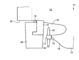
- FIG. 1 is a side view showing a stern of a ship according to Embodiment 1 of the present invention.
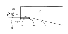
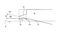
- FIG. 2 is a side view illustrating the stern shape of the ship according to the first embodiment.
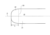
- FIG. 3 is a plan view illustrating the stern shape of the ship according to the first embodiment.
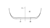
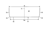
- FIG. 4 is a front view illustrating the stern shape of the ship according to the first embodiment.
- FIG. 5 is a graph showing the required horsepower with respect to the ship speed.
- FIG. 6 is a side view showing the stern shape of the ship according to the second embodiment of the present invention.
- FIG. 7 is a front view illustrating the stern shape of the ship according to the second embodiment.
- FIG. 8 is a side view illustrating the stern shape of the ship according to the third embodiment of the present invention.
- FIG. 9 is a side view showing the stern of a ship according to Embodiment 4 of the present invention.
- FIG. 10 is a front view illustrating the stern shape of the ship of the fourth embodiment.
- FIG. 11 is a graph showing the required horsepower with respect to the ship speed.
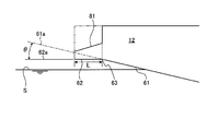
- FIG. 12 is a side view illustrating a stern shape of a ship according to the fifth embodiment of the present invention.
- FIG. 13 is a plan view illustrating the stern shape of the ship of the fifth embodiment.
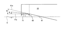
- FIG. 14 is a side view showing the stern shape of a ship according to Embodiment 6 of the present invention.
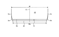
- FIG. 15 is a front view illustrating the stern shape of the ship of the sixth embodiment.
- FIG. 16 is a side view illustrating a stern shape of a ship according to Embodiment 7 of the present invention.
- FIG. 1 is a side view showing a stern of a ship according to a first embodiment of the present invention
- FIG. 2 is a side view showing a stern shape of the ship according to the first embodiment
- FIG. 3 is a stern shape of the ship according to the first embodiment
- FIG. 4 is a front view showing the stern shape of the ship of Example 1
- FIG. 5 is a graph showing the necessary horsepower with respect to the ship speed.
- the stern 12 in the hull 11 has a substantially horizontal ship bottom 13 extending rearward to form a bearing portion 14.
- a main shaft 15 is rotatably supported by the bearing portion 14, and a propeller boss 17 having a screw propeller 16 is fixed to a rear end portion of the main shaft 15.
- the ship bottom 13 is smoothly continuous up to above the propeller boss 17, a ladder horn 18 is fixed to the rear of the propeller boss 17, and a rudder 20 is supported by a stern 12 and a rudder column 19 installed on the ladder horn 18. Has been.
- the stern 12 has a predetermined distance set in advance from the first ship bottom 21 in which the ship bottom at the center line position in the width direction of the hull 11 is inclined upward and the stern end 12a.
- a second bottom 22 having an angle that is equal to or greater than an angle that is parallel to the planned draft S continuously from the first bottom 21 at a position that has moved forward only, and that is smaller than the angle of the rearward extension line from the first bottom 21.
- the second ship bottom 22 is set to 0 degree or more and 20 degrees or less with respect to the planned draft S.
- the first ship bottom 21 is preferably flat or gently curved, while the second ship bottom 22 is shaped to be horizontal before and after parallel to the planned draft S.
- the continuous part of the 1st ship bottom 21 and the 2nd ship bottom 22 is an inflection position which produces the flow field change accompanying a flow velocity change.
- the ship of the first embodiment is a general merchant ship having a transom stern, and an inflection point that should cause a flow field change accompanying a flow velocity change at a position moved forward by a predetermined distance from the stern end 12a. (Inflection position) is provided. And the 1st ship bottom 21 made to raise back by a plane or a gentle curved surface is formed so that a slow flow area may be formed ahead of the inflection point. On the other hand, a second bottom 22 is formed that has a predetermined distance from the stern end 12a and is inclined downward so as to generate a downward flow so as to form a region that accelerates the flow backward from the inflection point.
- the stern 12 has a symmetrical shape with respect to the center line C in the width direction of the hull 11.
- the first ship bottom 21 is a plane or a curved surface inclined upward from the ship bottom 13 by a predetermined angle ⁇ with respect to the planned draft S.
- the second bottom 22 is a horizontal plane that is continuous with the first bottom 21 at the inflection position 23 moved forward from the stern end 12a by a predetermined distance L and is parallel to the planned draft S.
- the second ship bottom 22 is within an angle formed by a horizontal line 22a parallel to the planned draft S and an extension line 21a extending rearward from the first ship bottom 21, and this angle is a rear of the horizontal line 22a of 0 degrees or more. And an inclination angle below the extension line 21a.
- predetermined angle it is preferable to set the upward inclination angle to the back with respect to planned draft S to 20 degrees or less.
- the inflection position 23 does not need to connect the first ship bottom 21 and the second ship bottom 22 at a predetermined angle, and may be smoothly continuous with a predetermined curved surface on the front and rear.
- the extension line 21 a from the first ship bottom 21 is a tangent to the first ship bottom 21 at the inflection position 23.
- the planned draft S is a draft in a state in which a load having a predetermined weight is loaded on the hull 11, and a draft in a state in which a load having a maximum weight allowable in structural strength is loaded on the hull 11 is a strength draft. It is. Therefore, the planned draft S is set so as to have a margin for the strength draft.
- the stern end 12a is in a state where the stern speed is low, and the resistance is greatly deteriorated due to the wave collapse occurring at the stern.
- the water flow that flows along the stern 12 flows from the first bottom 21 that inclines upward to the inflection position 23, and flows from the inflection position 23 to the horizontal second bottom 22, thereby the hull.
- the surface pressure increases, and the stern 12 is pushed upward by the hull surface pressure. Therefore, the settlement of the stern 12 is suppressed, and the hull resistance is reduced.
- the water flow that flows along the stern 12 flows rearward along the first bottom 21 and flows to the second bottom 22 so that the hull surface pressure increases. Is pushed upward, the settlement of the stern 12 is suppressed, and the hull resistance can be reduced. Moreover, since the 2nd ship bottom 22 does not incline below, the stern end 12a is hard to immerse in water, and also by suppressing the generation
- the angle of the second ship bottom 22 is set to 0 degree or more and 20 degrees or less with respect to the planned draft S. Accordingly, by setting the second bottom 22 to an appropriate angle with respect to the planned draft S, the stern 12 can be pushed up by the hull surface pressure and the stern wave can be prevented from being generated by the flooding of the stern end 12a of the second bottom 22. The hull resistance can be effectively reduced by this action.
- the 1st ship bottom 21 is made into the plane or a gentle curved surface shape
- the 2nd ship bottom 22 is made into the shape which becomes horizontal before and behind parallel to the plan draft S. Accordingly, the hull resistance can be further reduced by making the entire ship bottom smooth.
- the continuous part of the 1st ship bottom 21 and the 2nd ship bottom 22 is made into the inflection position 23 which produces the flow field change accompanying a flow velocity change. Therefore, by raising the hull surface pressure on the front side of the inflection position 23, the push-up action of the stern 12 by the hull surface pressure can be appropriately applied.
- FIG. 6 is a side view showing the stern shape of the ship according to the second embodiment of the present invention
- FIG. 7 is a front view showing the stern shape of the ship according to the second embodiment.
- symbol is attached
- the stern 12 is set in advance from the first ship bottom 21 in which the ship bottom located at the center line position in the width direction of the hull 11 is inclined upward and the stern end 12a.
- a second bottom 31 that forms an angle that is equal to or greater than an angle that is continuously parallel to the planned draft S and is smaller than the angle of the rearward extension line from the first bottom 21 at a position that has been moved forward by a predetermined distance. have.
- the first hull 21 is a flat surface or a curved surface inclined upward by a predetermined angle ⁇ with respect to the planned draft S from the bottom 13 to the rear.
- the second ship bottom 31 is continuous to the first vessel bottom 21 at the inflection location 23 has moved forward by a predetermined distance L set beforehand from the stern end 12a, inclined upward by a predetermined angle theta 1 with respect to planned draft S It is a plane.
- the predetermined angle ⁇ 1 of the second ship bottom 31 is smaller than the predetermined angle ⁇ of the first hull 21.
- the second ship bottom 31 parallel to the horizontal line 22a in plan draft S, there from the first vessel bottom 21 in the angle between the extension line 21a which extends rearward and has a predetermined angle theta 1 with respect to the horizontal line 22a It is a plane.
- the water flow that flows along the stern 12 flows from the first bottom 21 that inclines upward to the inflection position 23 side, and flows from the inflection position 23 to the second bottom 31 that inclines upward.
- the predetermined angle ⁇ 1 of the second hull 31 is smaller than the predetermined angle ⁇ of the first hull 21, the hull surface pressure increases here, and the stern 12 is pushed upward by this hull surface pressure. Therefore, the settlement of the stern 12 is suppressed, and the hull resistance is reduced.
- the draft rises to the strength draft, and the stern end 12a of the stern 12 may be immersed in the water.
- the second ship bottom 31 is inclined upward from the horizontal, the stern end 12a of the second ship bottom 31 is difficult to be immersed in water, and even if it is immersed in water, the amount thereof is small. And the deterioration of resistance is suppressed.
- the predetermined distance L set in advance from the first ship bottom 21 in which the ship bottom 13 at the position of the center line C in the width direction of the hull 11 is inclined upward and the stern end 12a.
- a second ship bottom 31 is provided which is continuous with the first ship bottom 21 at a position moved forward only and forms a predetermined angle ⁇ 1 smaller than the angle of the rearward extension line from the first ship bottom 21.
- the water flow that flows along the stern 12 flows rearward along the first bottom 21 and flows to the second bottom 31 so that the hull surface pressure increases. Is pushed upward, the settlement of the stern 12 is suppressed, and the hull resistance can be reduced. Moreover, since the 2nd ship bottom 31 does not incline below, the stern end 12a is hard to immerse in water, and it suppresses generation
- FIG. 8 is a side view showing the stern shape of a ship according to Example 3 of the present invention.
- symbol is attached
- symbol is attached
- the stern 12 has a predetermined first set from the stern end 12a and a first ship bottom 21 in which the ship bottom in the width direction center line position of the hull 11 is inclined upward rearward.
- a second bottom 22 having an angle that is equal to or greater than an angle that is continuous with the first bottom 21 and parallel to the planned draft S at a position that is moved forward by a distance and that is smaller than an angle of a rearward extension line from the first bottom 21. ing.
- the first hull 21 is a plane or a curved surface inclined upward from the ship bottom 13 by a predetermined angle ⁇ with respect to the planned draft S.
- the second ship bottom 22 is a plane that continues to the first ship bottom 21 at the inflection position 23 moved forward by a predetermined distance L from the stern end 12a and is parallel to the planned draft S.
- the stern 12 is provided with a recess 41 in a region facing the upper side of the second ship bottom 22.
- the concave portion 41 cuts the rear end portion of the stern 12 vertically from above and substantially horizontally from the rear.
- the vertical wall of the recess 41 may be a vertical surface, an inclined surface, or a curved surface, or the bottom wall of the recess 41 may be an inclined surface, a horizontal surface, or a curved surface.
- a second ship bottom 22 parallel to the planned draft S is provided continuously from the first ship bottom 21 at a position moved forward only, and a recess 41 is provided in the hull 11 facing above the second ship bottom 22.
- the hull weight can be reduced without reducing the propulsion performance, hull resistance can be reduced, and the manufacturing cost can be reduced. Can do.
- FIG. 9 is a side view showing the stern of a ship according to Example 4 of the present invention
- FIG. 10 is a front view showing the stern shape of the ship of Example 4
- FIG. 11 is a graph showing horsepower against ship speed. .
- the stern 12 in the hull 11 has a substantially horizontal ship bottom 13 extending rearward to form a bearing portion 14.
- a main shaft 15 is rotatably supported by the bearing portion 14, and a propeller boss 17 having a screw propeller 16 is fixed to a rear end portion of the main shaft 15.
- the ship bottom 13 is smoothly continuous up to above the propeller boss 17, a ladder horn 18 is fixed to the rear of the propeller boss 17, and a rudder 20 is supported by a stern 12 and a rudder column 19 installed on the ladder horn 18. Has been.
- the stern 12 includes a horizontal portion 52 that is a bottom portion, left and right side walls 53, left and right curved surface portions 54 that connect widthwise ends of the horizontal portion 52 and lower portions of the side walls 53. It consists of and.
- the horizontal portion 52 has a flat shape or a smooth curved surface shape in the front-rear direction, and a flat shape that forms a horizontal linear shape in the left-right (ship width) direction.
- Each side wall 53 has a flat surface or a gentle curved surface.
- the width Ws of the horizontal portion 52 at the stern bottom 51 is set to be 60% or more of the width W at the stern 12 (the hull 11).
- the width Ws of the horizontal portion 52 in the stern bottom 51 is preferably set to 60% or more and 95% or less of the width W in the stern 12 (the hull 11). This limitation takes into account work limitations.
- the bottom of the stern end 12a is curved in the width direction, or the horizontal area in the width direction is small, so in the region where the stern speed is low, the stern end 12a is immersed in water. A significant deterioration in resistance occurs due to the breaking of the waves.
- the horizontal portion of the stern bottom 51 is different from the conventional ship (dotted line) in which the bottom of the stern end 12a is curved in the width direction or the horizontal portion in the width direction is small.
- the ship of Example 4 (solid line) having a large width direction area 52 can reduce the necessary horsepower with respect to the ship speed.
- the stern 12 is placed at the stern bottom 51, the horizontal portion 52 serving as the bottom, the left and right side walls 53, and the end portions and the side walls in the width direction of the horizontal portion 52. 53.
- the width Ws of the horizontal part 52 in the stern bottom 51 is set to 60% or more of the width W in the stern 12 (the hull 11).
- the water flow that flows along the stern 12 flows rearward along the stern bottom 51 and flows to the horizontal portion 52 of the stern bottom 51, thereby increasing the hull surface pressure.
- the stern 12 is pushed upward, the settlement of the stern 12 is suppressed, and the hull resistance can be reduced.
- the width Ws of the horizontal part 52 in the stern bottom 51 is set to 60% or more and 95% or less of the width W in the stern 12 (the hull 11). Accordingly, the hull resistance can be further reduced by setting the width of the horizontal portion 52 to the optimum value.
- FIG. 12 is a side view showing the stern shape of the ship according to the fifth embodiment of the present invention
- FIG. 13 is a plan view showing the stern shape of the ship according to the fifth embodiment.
- symbol is attached
- the stern 12 is set in advance from the first ship bottom 61 in which the ship bottom at the center line position in the width direction of the hull 11 is inclined upward and the stern end 12a.
- a second bottom 62 that forms an angle that is equal to or greater than an angle that is continuously parallel to the planned draft S and is smaller than an angle of a rearward extension line from the first bottom 61 at a position that is moved forward by a predetermined distance. have.
- the second ship bottom 62 it is desirable to set the second ship bottom 62 to 0 degrees or more and 20 degrees or less with respect to the planned draft S.
- the first ship bottom 61 has a substantially flat planar shape or a gently curved surface shape, while the second ship bottom 62 has a shape that is horizontal before and after being parallel to the planned draft S.
- the continuous part of the 1st ship bottom 61 and the 2nd ship bottom 62 is the inflection position 63 which produces the flow field change accompanying a flow velocity change.
- the ship of the fifth embodiment is a general merchant ship having a transom stern, and an inflection point that should cause a flow field change accompanying a flow velocity change at a position moved forward by a predetermined distance from the stern end 12a.
- (Inflection position) 63 is provided.
- the first ship bottom 61 is formed to rise rearward by a flat surface or a gently curved surface so as to form a region with a low flow velocity in front of the inflection position 63.
- a second bottom 62 that has a predetermined distance from the stern end 12a and is inclined downward to generate a downward flow is formed so as to form a region that accelerates the flow backward from the inflection position 63.
- the stern 12 has a symmetrical shape with respect to the center line C in the width direction of the hull 11.
- the first ship bottom 61 is a flat surface or a curved surface inclined backward from the ship bottom 13 by a predetermined angle ⁇ with respect to the planned draft S.
- the second bottom 62 is a horizontal plane that is continuous with the first bottom 61 at the inflection position 63 moved forward by a predetermined distance L from the stern end 12a and parallel to the planned draft S.
- the inflection position 63 is curved and continuous with the side of the stern so that the inflection position 63 follows the shape of the stern end 12a. ing.
- the second ship bottom 62 is within an angle formed by a horizontal line 62a parallel to the planned draft S and an extension line 61a extending rearward from the first ship bottom 31.
- This angle is a rear of the horizontal line 62a of 0 degree or more.
- an inclination angle below the extension line 61a In this case, as for predetermined angle (theta), it is preferable to set the upward inclination angle to the back with respect to planned draft S to 20 degrees or less.
- the inflection position 63 does not need to connect the first ship bottom 61 and the second ship bottom 62 at a predetermined angle, and may be smoothly continuous with a predetermined curved surface on the front and rear.
- the extension line 61 a from the first ship bottom 61 is a tangent to the first ship bottom 61 at the inflection position 63.
- the planned draft S is a draft in a state in which a load having a predetermined weight is loaded on the hull 11, and a draft in a state in which a load having a maximum weight allowable in structural strength is loaded on the hull 11 is a strength draft. It is. Therefore, the planned draft S is set so as to have a margin for the strength draft.
- the stern bottom of the stern 12 is composed of a first bottom 61 and a second bottom 62.
- the stern 12 includes a horizontal portion 52, left and right side walls 53, and a curved surface portion 54 (refer to FIG. 10 above) at the second bottom 62 in the same manner as in the fourth embodiment described above.
- the width Ws of the horizontal portion 52 at 62 is set to 60% or more of the width W at the stern 12 (the hull 11).
- the stern end 12a is in a state where the stern speed is low, and the resistance is greatly deteriorated due to the wave collapse occurring at the stern.
- it is possible to secure a sufficient clearance from the still water surface by making the second ship bottom 62 horizontal, and the stern end 12a may be immersed in water in all regions from the high speed region to the low speed region. There is almost no hull resistance.
- the water flow that flows along the stern 12 flows from the first bottom 61 that inclines upward to the inflection position 63, and from the inflection position 63 to the horizontal portion 52 of the second bottom bottom 62.
- the hull surface pressure rises by flowing, and the stern 12 is pushed upward by this hull surface pressure. Therefore, the settlement of the stern 12 is suppressed, and the hull resistance is reduced.
- the draft may rise to the strength draft and the stern may be immersed in the water.
- the stern bottom is inclined downward, and the stern end 12a is likely to be immersed in water. Therefore, the stern wave is generated by the stern end 12a immersed in water, and the resistance is greatly deteriorated.
- the second ship bottom 62 is horizontal in the front-rear direction and the left-right direction, the second ship bottom 62 is difficult to be immersed in water, and even if it is immersed in water, the amount is small. The generation of stern waves is reduced, and the deterioration of resistance is suppressed.
- the predetermined distance L set in advance from the stern end 12a and the first ship bottom 61 in which the ship bottom 13 at the position of the center line C in the width direction of the hull 11 is inclined upward rearward.
- a second ship bottom 62 that is continuous with the first ship bottom 61 and parallel to the planned draft S at a position that has moved forward only, and the width Ws of the horizontal portion 52 at the second ship bottom 62 is 60% of the width W at the stern 12. It is set above.
- the water flow that flows along the stern 12 flows backward along the first bottom 61 and flows to the horizontal portion 52 of the second bottom 62, thereby increasing the hull surface pressure, and this hull surface.
- the stern 12 is pushed upward by the pressure, and the settlement of the stern 12 is suppressed, and the hull resistance can be reduced.
- the 2nd ship bottom 62 does not incline below, it is hard to be immersed in water, and also by suppressing the generation
- the angle of the second ship bottom 62 is set to 0 degree or more and 20 degrees or less with respect to the planned draft S. Therefore, by setting the second bottom 62 to an appropriate angle with respect to the planned draft S, the stern 12 is pushed up by the hull surface pressure and the generation of stern waves by the flooding of the stern end 12a of the second bottom 62 is suppressed. The hull resistance can be effectively reduced by this action.
- the 1st ship bottom 61 is made into a plane or a gentle curved surface shape
- the 2nd ship bottom 62 is made into the shape which becomes horizontal in the front and back parallel to the planned draft S. Accordingly, the hull resistance can be further reduced by making the entire ship bottom smooth.
- the continuous portion of the first bottom 61 and the second bottom 62 is set to an inflection position 63 that causes a flow field change accompanying a change in flow velocity. Therefore, by raising the hull surface pressure on the front side of the inflection position 63, the pushing-up action of the stern 12 by the hull surface pressure can be appropriately performed.
- FIG. 14 is a side view showing the stern shape of the ship according to the sixth embodiment of the present invention
- FIG. 15 is a front view showing the stern shape of the ship according to the sixth embodiment.
- symbol is attached
- the stern 12 is set in advance from the first ship bottom 61 in which the ship bottom at the center line position in the width direction of the hull 11 is inclined upward and the stern end 12 a.
- a second bottom 71 that forms an angle that is equal to or greater than an angle that is continuously parallel to the planned draft S and that is smaller than the angle of the rearward extension line from the first bottom 61 at a position that is moved forward by a predetermined distance. have.
- the first ship bottom 61 is a flat surface or a curved surface inclined upward by a predetermined angle ⁇ with respect to the planned draft S from the ship bottom 13 to the rear.
- the second ship bottom 71 is continuous to the first vessel bottom 61 at the inflection location 63 has moved forward by a predetermined distance L set beforehand from the stern end 12a, inclined upward by a predetermined angle theta 1 with respect to planned draft S It is a plane.
- the predetermined angle ⁇ 1 of the second ship bottom 71 is smaller than the predetermined angle ⁇ of the first ship bottom 61.
- the second ship bottom 71 parallel to the horizontal line 71a in plan draft S, there from the first vessel bottom 61 in the angle between the extension line 61a which extends rearward and has a predetermined angle theta 1 with respect to the horizontal line 71a It is a plane.
- the stern bottom of the stern 12 includes a first bottom 61 and a second bottom 71.
- the stern 12 includes a horizontal portion 72, left and right side walls 73, and a curved surface portion 74 at the second bottom 71, and the width Ws of the horizontal portion 72 in the second bottom 71 is equal to the stern 12 (the hull 11). It is set to 60% or more of the width W at.
- the water flow that flows along the stern 12 flows from the first bottom 61 that inclines upward to the inflection position 63 side, and then flows from the inflection position 63 to the second bottom 71 that inclines upward.
- the predetermined angle ⁇ 1 of the second hull 71 is smaller than the predetermined angle ⁇ of the first hull 61, the hull surface pressure increases here, and the stern 12 is pushed upward by this hull surface pressure. Therefore, the settlement of the stern 12 is suppressed, and the hull resistance is reduced.
- the draft will rise to the strength draft and the stern end 12a may be immersed in the water.
- the second ship bottom 71 is inclined upward from the horizontal, the stern end 12a of the second ship bottom 71 is difficult to be immersed in water, and even if it is immersed in water, the amount thereof is small. And the deterioration of resistance is suppressed.
- the predetermined distance L preset from the 1st ship bottom 61 in which the ship bottom 13 in the position of the center line C of the width direction of the hull 11 inclines backward, and the stern end 12a is preset.
- the water flow that flows along the stern 12 flows backward along the first bottom 61 and flows to the horizontal portion 72 of the second bottom 71, so that the hull surface pressure increases, and this hull surface increases.
- the stern 12 is pushed upward by the pressure, and the settlement of the stern 12 is suppressed, and the hull resistance can be reduced.
- the 2nd ship bottom 71 does not incline back downward, it is hard to be immersed in water, and also by suppressing generation
- FIG. 16 is a side view showing the stern shape of a ship according to Example 7 of the present invention.
- symbol is attached
- the stern 12 has a predetermined first set from a stern end 12a and a first ship bottom 61 in which the ship bottom in the width direction center line position of the hull 11 is inclined upward rearward.
- a second bottom 62 that forms an angle that is not less than the angle of the rearward extension line from the first bottom 61 but is greater than the angle that is parallel to the planned draft S continuously from the first bottom 61 at a position that has moved forward by a distance. ing.
- the first bottom 61 is a flat surface or a curved surface inclined upward by a predetermined angle ⁇ with respect to the planned draft S from the bottom 13 to the rear.
- the second ship bottom 62 is a plane that continues to the first ship bottom 61 at the inflection position 63 moved forward from the stern end 12a by a predetermined distance L and is parallel to the planned draft S.
- the stern bottom of the stern 12 includes a first bottom 61 and a second bottom 62.
- the stern 12 includes a horizontal portion 52, left and right side walls 53, and a curved surface portion 54 (refer to FIG. 10 above) at the second bottom 62 in the same manner as in the fourth embodiment described above.
- the width Ws of the horizontal portion 52 at 52 is set to 60% or more of the width W at the stern 12 (the hull 11).
- the stern 12 is provided with a recess 81 in a region facing the upper side of the second ship bottom 52.
- the concave portion 81 cuts the rear end portion of the stern 12 vertically from above and substantially horizontally from the rear.
- the vertical wall of the recess 81 may be a vertical surface, an inclined surface, or a curved surface, or the bottom wall of the recess 51 may be an inclined surface, a horizontal surface, or a curved surface.
- a second ship bottom 62 parallel to the planned draft S is provided continuously with the first ship bottom 61 at a position moved forward only, and the width Ws of the horizontal portion 52 at the second ship bottom 62 is 60% or more of the width W at the stern 12.
- a recess 81 is provided in the hull 11 facing above the second ship bottom 62.
- the hull weight can be reduced without reducing the propulsion performance, hull resistance can be reduced, and the manufacturing cost can be reduced. Can do.
- the shape of the bottom of the stern at the stern is raised and inclined rearward at a predetermined angle ⁇ , leveled in the middle, or angle ⁇ 1 , but is not limited to this structure. Instead, it may be inclined downwardly in the middle as in the prior art, the stern bottom itself may be horizontally or downwardly inclined, and may have a shape curved upward and downward and curved back and forth. That is, the width of the horizontal portion only needs to be set to a predetermined ratio regardless of the shape of the stern bottom.
- the ship of the present invention is not limited to the single-shaft ship described as each example, but a multi-shaft ship (two or more shafts) or other propulsion equipment-equipped ship (swing type POD propulsion device or azimuth propulsion). The same operational effects can be achieved.
- the present invention enables a reduction in hull resistance during cruising by setting the width of the horizontal part at the bottom of the stern to a predetermined ratio in a ship, and can be applied to any ship. .
Abstract
Description
12 船尾
12a 船尾端
13 船底
21,61 第1船底
22,31,62,71 第2船底
23,63 変曲位置(変曲点)
41,81 凹部
51 船尾船底
52,72 水平部
53,73 側壁
54,74 曲面部
Claims (8)
- 船体の幅方向中心線位置にある船底が後方へ上方傾斜した第1船底と、
船尾端から予め設定された所定距離だけ前方へ移動した位置で前記第1船底に連続して計画喫水に平行をなす角度以上で前記第1船底からの後方延長線の角度より小さい角度をなす第2船底と、
を備えることを特徴とする船舶。 - 前記第2船底は、計画喫水に対して0度以上で、且つ、20度以下に設定されることを特徴とする請求項1に記載の船舶。
- 前記第1船底は、平面またはなだらかな曲面形状をなし、前記第2船底は、計画喫水に平行な前後に水平となる形状をなすことを特徴とする請求項1または2に記載の船舶。
- 前記第1船底と前記第2船底の連続部は、流速変化を伴う流場変化を生じさせるような変曲位置であることを特徴とする請求項1から3のいずれか一つに記載の船舶。
- 前記第2船底の上方に対向する前記船体に凹部が設けられることを特徴とする請求項1から4のいずれか一つに記載の船舶。
- 船体の船尾端は、左右の側壁における下部と、船底における幅方向の各端部が曲面部により連結されて構成され、前記船底における水平部の幅が前記船体の船尾端における幅の60%以上に設定されることを特徴とする請求項1から5のいずれか一つに記載の船舶。
- 前記船底における水平部の幅は、前記船体の船尾端における幅の60%以上で且つ95%以下に設定されることを特徴とする請求項6に記載の船舶。
- 前記第2船底にて、水平部の幅が前記船体の幅の所定割合に設定されることを特徴とする請求項6または7に記載の船舶。
Priority Applications (5)
| Application Number | Priority Date | Filing Date | Title |
|---|---|---|---|
| EP11845765.4A EP2647565B1 (en) | 2010-12-02 | 2011-10-20 | Ship |
| US13/877,357 US9205891B2 (en) | 2010-12-02 | 2011-10-20 | Transom-stern-type stern shape of vessel |
| KR1020137010475A KR20130098378A (ko) | 2010-12-02 | 2011-10-20 | 선박 |
| CN201180051286.0A CN103180203B (zh) | 2010-12-02 | 2011-10-20 | 船舶 |
| KR1020157001859A KR101654489B1 (ko) | 2010-12-02 | 2011-10-20 | 선박 |
Applications Claiming Priority (4)
| Application Number | Priority Date | Filing Date | Title |
|---|---|---|---|
| JP2010-269505 | 2010-12-02 | ||
| JP2010269505A JP5863235B2 (ja) | 2010-12-02 | 2010-12-02 | 船舶 |
| JP2010-269504 | 2010-12-02 | ||
| JP2010269504A JP5896598B2 (ja) | 2010-12-02 | 2010-12-02 | 船舶 |
Publications (1)
| Publication Number | Publication Date |
|---|---|
| WO2012073614A1 true WO2012073614A1 (ja) | 2012-06-07 |
Family
ID=46171566
Family Applications (1)
| Application Number | Title | Priority Date | Filing Date |
|---|---|---|---|
| PCT/JP2011/074200 WO2012073614A1 (ja) | 2010-12-02 | 2011-10-20 | 船舶 |
Country Status (5)
| Country | Link |
|---|---|
| US (1) | US9205891B2 (ja) |
| EP (1) | EP2647565B1 (ja) |
| KR (2) | KR101654489B1 (ja) |
| CN (1) | CN103180203B (ja) |
| WO (1) | WO2012073614A1 (ja) |
Cited By (1)
| Publication number | Priority date | Publication date | Assignee | Title |
|---|---|---|---|---|
| JP2012116402A (ja) * | 2010-12-02 | 2012-06-21 | Mitsubishi Heavy Ind Ltd | 船舶 |
Families Citing this family (2)
| Publication number | Priority date | Publication date | Assignee | Title |
|---|---|---|---|---|
| JP6181615B2 (ja) * | 2014-08-08 | 2017-08-16 | 三井造船株式会社 | 洋上浮体構造物 |
| CN106627978A (zh) * | 2017-01-05 | 2017-05-10 | 浙江大学 | 带有pod吊舱推进器的新型集装箱船 |
Citations (4)
| Publication number | Priority date | Publication date | Assignee | Title |
|---|---|---|---|---|
| JPS49111389A (ja) * | 1973-02-27 | 1974-10-23 | ||
| JPS5973384A (ja) * | 1982-10-18 | 1984-04-25 | Mitsui Eng & Shipbuild Co Ltd | 船体抵抗減少装置 |
| JPS61171683A (ja) * | 1985-01-24 | 1986-08-02 | Mitsubishi Heavy Ind Ltd | 2軸型高速艇 |
| JP3490392B2 (ja) | 2000-11-22 | 2004-01-26 | 株式会社川崎造船 | トランサムスターン型船尾形状 |
Family Cites Families (14)
| Publication number | Priority date | Publication date | Assignee | Title |
|---|---|---|---|---|
| US1717286A (en) * | 1927-09-14 | 1929-06-11 | Charles E Ward | Rudder control for towboats |
| JPS51132594A (en) * | 1975-04-04 | 1976-11-17 | Tommasi Di Vignano G B | Ship |
| DE3005682C2 (de) * | 1980-01-28 | 1982-11-11 | Escher Wyss Gmbh, 7980 Ravensburg | Schiffantriebsanlage |
| JPS6057498U (ja) * | 1983-09-27 | 1985-04-22 | 川崎重工業株式会社 | 作業船の船体構造 |
| CA1237607A (en) * | 1986-01-28 | 1988-06-07 | Peter J. Van Diepen | Ship's stern bulb |
| DE4138281C1 (ja) * | 1991-11-02 | 1993-04-29 | Herbert Prof. Dr.-Ing. 5100 Aachen De Schneekluth | |
| RU2053914C1 (ru) * | 1992-11-02 | 1996-02-10 | Виктор Петрович Соколов | Кормовая оконечность корпуса водоизмещающего судна |
| RU2063356C1 (ru) * | 1992-12-31 | 1996-07-10 | Центральное конструкторское бюро "Вымпел" | Кормовая оконечность корпуса судна |
| JPH08133172A (ja) * | 1994-11-09 | 1996-05-28 | Ishikawajima Harima Heavy Ind Co Ltd | ツイン・スケグ船型の船尾形状 |
| US5841045A (en) * | 1995-08-23 | 1998-11-24 | Nanodyne Incorporated | Cemented carbide articles and master alloy composition |
| CN2377170Y (zh) * | 1999-04-06 | 2000-05-10 | 吴大文 | 尾翼船 |
| WO2008099462A1 (ja) * | 2007-02-13 | 2008-08-21 | Mitsubishi Heavy Industries, Ltd. | 排水量型船舶の船尾形状 |
| JP5030879B2 (ja) | 2008-07-14 | 2012-09-19 | 三菱重工業株式会社 | 低振動船舶構造及びその設計方法 |
| KR20100127854A (ko) * | 2008-10-20 | 2010-12-06 | 미츠비시 쥬고교 가부시키가이샤 | 트윈 스케그선 |
-
2011
- 2011-10-20 CN CN201180051286.0A patent/CN103180203B/zh active Active
- 2011-10-20 WO PCT/JP2011/074200 patent/WO2012073614A1/ja active Application Filing
- 2011-10-20 KR KR1020157001859A patent/KR101654489B1/ko active IP Right Grant
- 2011-10-20 EP EP11845765.4A patent/EP2647565B1/en active Active
- 2011-10-20 US US13/877,357 patent/US9205891B2/en not_active Expired - Fee Related
- 2011-10-20 KR KR1020137010475A patent/KR20130098378A/ko active Application Filing
Patent Citations (4)
| Publication number | Priority date | Publication date | Assignee | Title |
|---|---|---|---|---|
| JPS49111389A (ja) * | 1973-02-27 | 1974-10-23 | ||
| JPS5973384A (ja) * | 1982-10-18 | 1984-04-25 | Mitsui Eng & Shipbuild Co Ltd | 船体抵抗減少装置 |
| JPS61171683A (ja) * | 1985-01-24 | 1986-08-02 | Mitsubishi Heavy Ind Ltd | 2軸型高速艇 |
| JP3490392B2 (ja) | 2000-11-22 | 2004-01-26 | 株式会社川崎造船 | トランサムスターン型船尾形状 |
Cited By (1)
| Publication number | Priority date | Publication date | Assignee | Title |
|---|---|---|---|---|
| JP2012116402A (ja) * | 2010-12-02 | 2012-06-21 | Mitsubishi Heavy Ind Ltd | 船舶 |
Also Published As
| Publication number | Publication date |
|---|---|
| KR20130098378A (ko) | 2013-09-04 |
| US20130186318A1 (en) | 2013-07-25 |
| EP2647565A4 (en) | 2017-12-06 |
| KR20150016642A (ko) | 2015-02-12 |
| EP2647565B1 (en) | 2020-05-06 |
| CN103180203A (zh) | 2013-06-26 |
| US9205891B2 (en) | 2015-12-08 |
| KR101654489B1 (ko) | 2016-09-05 |
| CN103180203B (zh) | 2018-11-23 |
| EP2647565A1 (en) | 2013-10-09 |
Similar Documents
| Publication | Publication Date | Title |
|---|---|---|
| JP5412259B2 (ja) | 船 | |
| CN101704401A (zh) | 一种深v滑行艇艇型 | |
| JP2008260445A (ja) | 船舶 | |
| JP3571023B2 (ja) | 船舶の船首形状 | |
| JP4889238B2 (ja) | 船首フィン付き船舶 | |
| JP5095521B2 (ja) | 船体構造 | |
| JP2007223557A (ja) | ツイン・スケグ船 | |
| WO2012073614A1 (ja) | 船舶 | |
| JP5868805B2 (ja) | 肥大船 | |
| JP5896598B2 (ja) | 船舶 | |
| US9284019B2 (en) | Ellipsoidal V-hull | |
| JP5863235B2 (ja) | 船舶 | |
| JP4938056B2 (ja) | 船尾波干渉フィン | |
| JP2005537175A (ja) | 喫水線よりも下に位置するフォイルを備えた船舶 | |
| JP5393160B2 (ja) | 排水量型船舶の船尾形状 | |
| CN109070986B (zh) | 船舶用舵及船舶 | |
| JP2006051895A (ja) | 高速船における船尾構造 | |
| JP3134108U (ja) | 船尾端フィン | |
| JP5030884B2 (ja) | 船尾形状 | |
| JP5143510B2 (ja) | 船体構造 | |
| JP2012180021A (ja) | 船舶 | |
| JP4703244B2 (ja) | 舶用一軸二舵システムおよび一軸二舵船舶 | |
| JP5634567B2 (ja) | 排水量型船舶の船尾形状 | |
| JP2016155511A (ja) | 船舶 | |
| EP3154850B1 (en) | Hull for low drag boats |
Legal Events
| Date | Code | Title | Description |
|---|---|---|---|
| 121 | Ep: the epo has been informed by wipo that ep was designated in this application |
Ref document number: 11845765 Country of ref document: EP Kind code of ref document: A1 |
|
| WWE | Wipo information: entry into national phase |
Ref document number: 13877357 Country of ref document: US |
|
| WWE | Wipo information: entry into national phase |
Ref document number: 2011845765 Country of ref document: EP |
|
| ENP | Entry into the national phase |
Ref document number: 20137010475 Country of ref document: KR Kind code of ref document: A |
|
| NENP | Non-entry into the national phase |
Ref country code: DE |