WO2012073319A1 - 超音波振動接合装置 - Google Patents
超音波振動接合装置 Download PDFInfo
- Publication number
- WO2012073319A1 WO2012073319A1 PCT/JP2010/071333 JP2010071333W WO2012073319A1 WO 2012073319 A1 WO2012073319 A1 WO 2012073319A1 JP 2010071333 W JP2010071333 W JP 2010071333W WO 2012073319 A1 WO2012073319 A1 WO 2012073319A1
- Authority
- WO
- WIPO (PCT)
- Prior art keywords
- ultrasonic vibration
- substrate
- glass substrate
- vibration bonding
- bonding apparatus
- Prior art date
- Legal status (The legal status is an assumption and is not a legal conclusion. Google has not performed a legal analysis and makes no representation as to the accuracy of the status listed.)
- Ceased
Links
Images





Classifications
-
- B—PERFORMING OPERATIONS; TRANSPORTING
- B23—MACHINE TOOLS; METAL-WORKING NOT OTHERWISE PROVIDED FOR
- B23K—SOLDERING OR UNSOLDERING; WELDING; CLADDING OR PLATING BY SOLDERING OR WELDING; CUTTING BY APPLYING HEAT LOCALLY, e.g. FLAME CUTTING; WORKING BY LASER BEAM
- B23K20/00—Non-electric welding by applying impact or other pressure, with or without the application of heat, e.g. cladding or plating
- B23K20/002—Non-electric welding by applying impact or other pressure, with or without the application of heat, e.g. cladding or plating specially adapted for particular articles or work
-
- B—PERFORMING OPERATIONS; TRANSPORTING
- B23—MACHINE TOOLS; METAL-WORKING NOT OTHERWISE PROVIDED FOR
- B23K—SOLDERING OR UNSOLDERING; WELDING; CLADDING OR PLATING BY SOLDERING OR WELDING; CUTTING BY APPLYING HEAT LOCALLY, e.g. FLAME CUTTING; WORKING BY LASER BEAM
- B23K20/00—Non-electric welding by applying impact or other pressure, with or without the application of heat, e.g. cladding or plating
- B23K20/10—Non-electric welding by applying impact or other pressure, with or without the application of heat, e.g. cladding or plating making use of vibrations, e.g. ultrasonic welding
Definitions
- the present invention relates to an ultrasonic vibration bonding apparatus, and the ultrasonic vibration bonding apparatus according to the present invention can be used, for example, when an object to be processed is ultrasonic vibration bonded to a thin substrate.
- ultrasonic vibration bonding As a technique for bonding an object to be processed such as a conductive member to a substrate (for example, see Patent Documents 1 and 2).
- An object to be processed is placed on the substrate, a bonding tool is brought into contact with the object to be processed with a predetermined pressure, and the bonding tool is subjected to ultrasonic vibration in the horizontal direction. Thereby, a to-be-processed object is joined on a board
- the ultrasonic vibration joining process may be applied.
- the present invention provides ultrasonic waves that can normally ultrasonically bond a workpiece to be processed on a substrate without damaging the substrate even if the substrate is distorted or warped.
- An object is to provide a vibration bonding apparatus.
- an ultrasonic vibration bonding apparatus is an ultrasonic vibration bonding apparatus capable of ultrasonic vibration bonding of an object to be processed to a substrate.
- An ultrasonic vibration unit capable of applying horizontal ultrasonic vibration while applying pressure to the object to be processed, a table on which the substrate is placed, and the object to be processed in the ultrasonic vibration unit;
- a receiving portion that can receive the substrate from below, and the ultrasonic vibration portion is configured such that the substrate is received by the receiving portion. In the state, the ultrasonic vibration is applied to the object to be processed.
- An ultrasonic vibration bonding apparatus is an ultrasonic vibration bonding apparatus that can ultrasonically bond an object to be processed to a substrate.
- the ultrasonic vibration bonding apparatus performs horizontal superposition while applying pressure from above.
- the table on which the substrate is placed In a position corresponding to the contact portion of the ultrasonic vibration unit that can apply ultrasonic vibration to the object to be processed, the table on which the substrate is placed, and the ultrasonic wave vibration unit.
- a receiving portion capable of receiving the substrate from below, and the ultrasonic vibration portion is disposed on the object to be processed in a state where the substrate is received by the receiving portion. Then, the ultrasonic vibration is applied.
- the ultrasonic vibration bonding apparatus can properly ultrasonically move an object to be processed on the substrate without damaging the substrate even if the substrate is distorted or warped. Can be vibration bonded.
- FIG. 1 is a cross-sectional view illustrating a schematic configuration of an ultrasonic vibration bonding apparatus 100 according to Embodiment 1.
- FIG. FIG. 10 is a diagram for illustrating a control operation of receiving unit 15 according to the second embodiment. It is an expanded sectional view which shows the structure of the receiving part 15 by which the contact detection sensor 20 based on Embodiment 3 is arrange
- FIG. 6 is an enlarged cross-sectional view for explaining the operation of the contact detection sensor 21 disposed in the receiving unit 15.
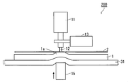
- FIG. 6 is a cross-sectional view illustrating a schematic configuration of an ultrasonic vibration bonding apparatus 200 according to Embodiment 4.
- FIG. 10 is a cross-sectional view for explaining the operation of an ultrasonic vibration bonding apparatus 200 according to Embodiment 4.
- FIG. 6 is a cross-sectional view illustrating a schematic configuration of an ultrasonic vibration bonding apparatus 300 according to Embodiment 5.
- FIG. 10 is a cross-sectional view illustrating a schematic configuration of an ultrasonic vibration bonding apparatus 300 according to Embodiment 5.
- a glass substrate used in a solar cell is subjected to a film formation process or a heat treatment in order to form a PN junction or the like. Due to the film forming process or the heat treatment, distortion and warping of various shapes and sizes occur in the thin glass substrate.
- FIG. 1 is a cross-sectional view showing a configuration of an ultrasonic vibration bonding apparatus 100 according to the present embodiment.
- local warpage 1 a occurs in the glass substrate 1.
- a scene in which the lead wire 2 is ultrasonically vibration bonded to the glass substrate 1 where the warp 1 a is generated is illustrated.
- the ultrasonic vibration bonding apparatus 100 includes a pressurizing mechanism 11, a bonding tool 12, an ultrasonic transducer 13, a table 14, and a receiving unit 15.
- the pressurizing mechanism 11, the joining tool 12, and the ultrasonic vibrator 13 constitute an ultrasonic vibration unit.
- the pressurizing mechanism 11 applies a predetermined pressure (for example, a pressure of about 50 kg) to the welding tool 12 from the upper direction to the lower direction in FIG. Can do. Further, the ultrasonic transducer 13 can apply ultrasonic vibration in the horizontal direction (for example, 20 kHz in the front and back direction of the paper in FIG. 1) to the bonding tool 12.
- a predetermined pressure for example, a pressure of about 50 kg
- the ultrasonic transducer 13 can apply ultrasonic vibration in the horizontal direction (for example, 20 kHz in the front and back direction of the paper in FIG. 1) to the bonding tool 12.
- the glass substrate 1 is placed and fixed on the table 14, and the lead wire 2 is placed at a predetermined position on the glass substrate 1. Has been placed. Then, the joining tool 12 is brought into contact with the lead wire 2. Then, the welding tool 12 is ultrasonically vibrated in the horizontal direction while applying a predetermined pressure from above to the lead wire 2 via the welding tool 12. As a result, the lead wire 2 can be ultrasonically bonded to the glass substrate 1.
- a hole 14a having a desired size and shape is formed in the table 14 on which the glass substrate 1 is placed.
- the elongated hole 14 a is formed in the table 14 according to the joining position of the lead wire 2. It may be perforated.
- the receiving unit 15 can move in the vertical direction so that the glass substrate 1 can be contacted or non-contacted. Moreover, the receiving part 15 exists in the position corresponding to the contact part with the lead wire 2 in the joining tool 12, and can receive the glass substrate 1 from a downward direction. In the ultrasonic vibration bonding apparatus 100 according to the present embodiment, the upper surface portion of the receiving portion 15 directly contacts the lower surface of the glass substrate 1 through the hole 14a, so that the receiving portion 15 is fixed to the table 14. A glass substrate 1 is received. In the present embodiment, the table 14 does not move up and down and is fixed.
- the receiving unit 15 moves upward during the ultrasonic vibration bonding process. And in the joining part, the glass substrate 1 and the lead wire 2 are inserted
- the glass substrate 1 is placed and fixed on the table 14, and the lead wire 2 is arranged at the bonding position on the glass substrate 1.
- the receiving part 15 is moved upward, and the upper surface part of the receiving part 15 is brought into contact with the lower surface of the glass substrate 1 through the hole 14a.
- the contact tool 12 is brought into contact with the lead wire 2.
- a predetermined pressure is applied to the welding tool 12 in the downward direction in FIG. While applying the pressure, the ultrasonic vibrator 13 applies the ultrasonic vibration in the horizontal direction of FIG. 1 to the welding tool 12 (ultrasonic vibration bonding process).
- the glass substrate 1 and the lead wire 2 can be bonded at the bonding position.
- the receiving unit 15 is moved downward in FIG. 1 to eliminate “receiving” of the glass substrate 1 by the receiving unit 15.
- the receiving unit 15 can receive the lower surface of the glass substrate 1. And ultrasonic vibration joining by the ultrasonic vibration parts 11, 12, 13 can be performed on the lead wire 2 arranged on the glass substrate 1 above the receiving part 15.
- the ultrasonic vibration bonding apparatus 100 does not cause damage to the glass substrate 1, for example, even if the glass substrate 1 is distorted or warped. Sonic vibration bonding is possible.
- several holes 14a or one predetermined shape is set so that the table 14 corresponding to the said joining position may open in planar view according to several joining positions. May be provided in the table 14.
- a long and narrow hole 14a may be formed in the table 14 in accordance with the joining position of the lead wire 2 (the hole). 14a exists in the position corresponding to each joining position).
- ultrasonic vibration joining at a plurality of points of the glass substrate 1 and the lead wire 2 is made possible by moving the ultrasonic vibration parts 11, 12, 13 and the receiving part 15 or the table 14 in the horizontal direction. Processing can be performed continuously.
- the receiving unit 15 is composed of an air cylinder or a hydraulic cylinder, and the following control is performed (FIG. 2).
- the vertical axis in FIG. 2 is the pressure exerted by the receiving portion 15 on the glass substrate 1, and the horizontal axis in FIG. 2 is time.
- the receiving portion 15 is moved upward in FIG. 1, and the upper surface of the receiving portion 15 is placed on the lower surface of the glass substrate 1 placed and fixed on the table 14 through the hole 14a. Touch (start contact). After the contact, the upward pressure applied to the glass substrate 1 by the receiving portion 15 is increased by continuing the upward movement.
- the upward movement of the receiving unit 15 (in other words, the pressurization) is stopped ( Lock at the specified pressure value). Thereafter, in a state where the receiving unit 15 receives the glass substrate 1 at a predetermined pressure value, ultrasonic vibration joining processing by the ultrasonic vibration units 11, 12, and 13 is performed.
- the predetermined pressure value is determined by the material and thickness of the glass substrate 1 and is determined within a range in which the glass substrate 1 is not damaged.
- the receiving unit 15 After the ultrasonic vibration bonding process, the receiving unit 15 starts to move downward in FIG. 1 and cancels reception of the glass substrate 1 by the receiving unit 15 (end of contact). Furthermore, the receiving part 15 continues the downward movement to a predetermined position.
- the ultrasonic vibration bonding apparatus 100 receives the glass substrate 1 at a predetermined pressure value, while the ultrasonic vibration units 11, 12, and 13 The ultrasonic vibration bonding process can be performed on the lead wire 2.
- 3, 4, and 5 are diagrams illustrating a contact-type contact detection sensor disposed in the receiving unit 15.
- a contact detection sensor 20 such as a piezoelectric element is embedded in the receiving unit 15.
- the upper surface of the receiving unit 15 and the upper surface of the contact detection sensor 20 are flush with each other, and the contact detection sensor 20 can detect that the lower surface of the glass substrate 1 is in contact with the receiving unit 15.
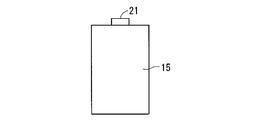
- a pin-like contact detection sensor 21 is provided so as to protrude from the upper surface of the receiving portion 15. As shown in FIG. 5, when the lower surface of the glass substrate 1 comes into contact with the receiving portion 15, the contact detection sensor 21 falls into the receiving portion 15, thereby confirming that the upper surface of the receiving portion 15 comes into contact with the glass substrate 1. Detect.
- the receiving unit 15 moves upward in FIG. 1, and the sensors 20 and 21 detect that the upper surface of the receiving unit 15 and the lower surface of the glass substrate 1 fixed to the table 14 are in contact with each other. Then, the receiving unit 15 stops the upward movement. Then, in the state where the glass substrate 1 is in contact with the receiving portion 15, ultrasonic vibration bonding processing by the ultrasonic vibration portions 11, 12, 13 is performed.
- the receiving unit 15 After the ultrasonic vibration bonding process, the receiving unit 15 starts to move downward in FIG. 1 and cancels reception of the glass substrate 1 by the receiving unit 15 (end of contact). Furthermore, the receiving part 15 continues the downward movement to a predetermined position.
- a sensor for detecting contact with the glass substrate 1 is disposed in the receiving portion 15. Therefore, in the ultrasonic vibration bonding apparatus 100, the ultrasonic vibration portions 11, 12, and 13 perform ultrasonic vibration bonding processing on the lead wire 2 in a state where the receiving portion 15 is reliably receiving the glass substrate 1. be able to.
- FIG. 6 is a cross-sectional view showing the configuration of the ultrasonic vibration bonding apparatus 200 according to the present embodiment.
- local warpage 1 a occurs in the glass substrate 1.
- the configuration of the ultrasonic vibration bonding apparatus 200 according to the present embodiment and the ultrasonic vibration bonding apparatus 100 according to the first embodiment are different in the following points.
- a table 31 made of a thin resin (for example, 5 mm or less) is provided instead of the table 14. Further, unlike the table 14, the hole 31 a is not drilled in the table 31 according to the present embodiment. The configuration other than these is the same in both ultrasonic vibration bonding apparatuses 100 and 200.
- the receiving unit 15 moves upward during the ultrasonic vibration bonding process. Then, the table 31, the glass substrate 1, and the lead wire 2 are sandwiched between the joining tool 12 and the receiving portion 15 at the joining portion. Then, in a state where the receiving unit 15 indirectly receives the lower surface of the glass substrate 1 through the table 31, the bonding tool 12 performs ultrasonic vibration while applying pressure to the lead wire 2.
- the receiving unit 15 moves in the vertical direction, but the table 14 does not move up and down and is fixed.
- the glass substrate 1 is placed and fixed on the table 31, and the lead wire 2 is placed at the bonding position on the glass substrate 1.
- the receiving part 15 is moved upward.
- the upper surface portion of the receiving portion 15 indirectly receives the lower surface of the glass substrate 1 fixed to the table 31 through the deformed table 31.
- the contact tool 12 is brought into contact with the lead wire 2.
- the table 31 the glass substrate 1, and the lead wire 2 are sandwiched between the joining tool 12 and the receiving portion 15 at the contact portion.
- a predetermined pressure is applied to the welding tool 12 in the downward direction in FIG. While applying the pressure, the ultrasonic vibrator 13 applies ultrasonic vibration in the horizontal direction of FIG. 7 to the welding tool 12 (ultrasonic vibration bonding processing).
- the glass substrate 1 and the lead wire 2 can be bonded at the bonding position.
- the receiving unit 15 is moved downward in FIG. 7 to eliminate indirect “receiving” of the glass substrate 1 by the receiving unit 15. Then, as shown in FIG. 6, the “deformation” generated in the table 31 is also restored by eliminating the “reception” by the receiving unit 15.
- the ultrasonic vibration bonding apparatus 200 it is possible to receive the lower surface of the glass substrate 1 indirectly by the receiving unit 15. And ultrasonic vibration joining by the ultrasonic vibration parts 11, 12, 13 can be performed on the lead wire 2 arranged on the glass substrate 1 above the receiving part 15.
- the ultrasonic vibration bonding apparatus 200 does not damage the glass substrate 1, for example, even if the glass substrate 1 is distorted or warped. Sonic vibration bonding is possible.
- the table 31 according to the present embodiment is made of a thin hard resin. Accordingly, since the table 31 is easily deformed by being pushed up from the receiving portion 15, it is not necessary to provide the hole 31 a as described in the first embodiment in the table 31.
- ultrasonic vibration bonding processing at a plurality of points of the glass substrate 1 and the lead wire 2 is performed. Can be performed continuously. In other words, the ultrasonic vibration units 11, 12, 13 and the receiving unit 15, or the table 14 can be moved in the horizontal direction, so that the glass substrate 1, the lead wire 2, The ultrasonic vibration bonding process can be performed.
- the receiving unit 15 is fixed, and the table 31 moves in the vertical direction. Is received. Except for this operation, the configurations and operations of the ultrasonic vibration bonding apparatuses 200 and 300 are the same.
- the glass substrate 1 is placed and fixed on the table 31, and the lead wire 2 is placed at the bonding position on the glass substrate 1.
- the table 31 is moved downward. Thereby, as shown in FIG. 8, the table 31 deform
- the contact tool 12 is brought into contact with the lead wire 2.
- the table 31, the glass substrate 1, and the lead wire 2 are sandwiched between the joining tool 12 and the receiving portion 15 in the contact portion.
- a predetermined pressure is applied to the welding tool 12 in the downward direction in FIG. While applying the pressure, the ultrasonic vibrator 13 applies ultrasonic vibration in the horizontal direction of FIG. 8 to the welding tool 12 (ultrasonic vibration bonding processing).
- the glass substrate 1 and the lead wire 2 can be bonded at the bonding position.
- the table 31 is moved upward in FIG. 8 to eliminate indirect “receiving” of the glass substrate 1 by the receiving unit 15. Then, as shown in FIG. 6, the “deformation” generated in the table 31 is also restored by eliminating the “reception” by the receiving unit 15.
- the ultrasonic vibration bonding apparatus 300 can receive the lower surface of the glass substrate 1 indirectly by the receiving unit 15. And ultrasonic vibration joining by the ultrasonic vibration parts 11, 12, 13 can be performed on the lead wire 2 arranged on the glass substrate 1 above the receiving part 15.
- the ultrasonic vibration bonding apparatus 300 normally extends the lead wire 2 over the glass substrate 1 without damaging the glass substrate 1 even if the glass substrate 1 is distorted or warped. Sonic vibration bonding is possible.
- the table 31 according to the present embodiment is made of a thin hard resin. Therefore, since the table 31 is easily deformed by the contact with the receiving portion 15, it is not necessary to provide the hole 31 a as described in the first embodiment in the table 31.
- the ultrasonic vibration bonding apparatus 300 having the above-described effect is provided even when the vertical movement of the receiving unit 15 is difficult due to the convenience of the apparatus configuration, for example. Can be configured.
- ultrasonic vibration bonding processing at a plurality of points of the glass substrate 1 and the lead wire 2 is performed. Can be performed continuously. In other words, the ultrasonic vibration units 11, 12, 13 and the receiving unit 15, or the table 14 can be moved in the horizontal direction, so that the glass substrate 1, the lead wire 2, The ultrasonic vibration bonding process can be performed.
Landscapes
- Engineering & Computer Science (AREA)
- Mechanical Engineering (AREA)
- Pressure Welding/Diffusion-Bonding (AREA)
- Joining Of Glass To Other Materials (AREA)
Abstract
本発明は、たとえば基板に歪や反りが発生していたとしても、当該基板に対してダメージを与えること無く、正常に基板上に被処理体を超音波振動接合することができる超音波振動接合装置を提供する。そこで、本発明に係る超音波振動接合装置(100,200,300)は、超音波振動接合処理を行う超音波振動部(11,12,13)と、基板(1)が載置されるテーブル(14,31)と、超音波振動部(11,12,13)における被処理体(2)との当接部に対応した位置に存し、基板(1)を下方向から受けることが可能な受部(15)とを、備えている。そして、超音波振動部(11,12,13)は、基板(1)が受部(15)により受けられている状態で、被処理体(2)に対して前記超音波振動の印加を行う。
Description
本発明は、超音波振動接合装置に関する発明であり、本発明に係る超音波振動接合装置は、たとえば、薄厚の基板に対して被処理体を超音波振動接合する際に利用することができる。
基板に対して導電性部材等の被処理体を接合するための技術として、超音波振動接合というものがある(たとえば、特許文献1,2参照)。
基板上に被処理体を配置させ、当該被処理体に所定の圧力で接合ツールを当接し、当該接合ツールを水平方向に超音波振動をさせる。これにより、被処理体が基板上に接合される。
太陽電池の分野においては、たとえば、ガラス基板に形成された電極層にリード線を接合する際に、当該超音波振動接合処理を適用することも考えられる。
ところで、厚さ数mm以下の基板に対して、成膜処理や熱処理を施すと、局所的または広い範囲に渡って歪や反りが発生することがある。当該歪等が発生した基板に対して、超音波振動接合処理を施すと、超音波振動が正常に伝達されず、接合不良が発生する。
超音波振動接合処理前に、基板の歪や反りを矯正することも考えられる。しかしながら、当該矯正のために、非常に高い圧力を基板に与える必要があり、たとえば基板が薄厚のガラス基板であるなどの場合には、当該矯正により基板が損傷を受けてしまう。
そこで、本発明は、たとえば基板に歪や反りが発生していたとしても、当該基板に対してダメージを与えること無く、正常に基板上に被処理体を超音波振動接合することができる超音波振動接合装置を提供することを目的とする。
上記の目的を達成するために、本発明に係る超音波振動接合装置は、基板に対して被処理体を超音波振動接合することができる超音波振動接合装置であって、上方向からの加圧を行いながらの水平方向の超音波振動を、前記被処理体に印加することができる超音波振動部と、前記基板が載置されるテーブルと、前記超音波振動部における前記被処理体との当接部に対応した位置に存し、前記基板を下方向から受けることが可能な受部とを、備えており、前記超音波振動部は、前記基板が前記受部により受けられている状態で、前記被処理体に対して前記超音波振動の印加を行う。
本発明に係る超音波振動接合装置は、基板に対して被処理体を超音波振動接合することができる超音波振動接合装置であって、上方向からの加圧を行いながらの水平方向の超音波振動を、前記被処理体に印加することができる超音波振動部と、前記基板が載置されるテーブルと、前記超音波振動部における前記被処理体との当接部に対応した位置に存し、前記基板を下方向から受けることが可能な受部とを、備えており、前記超音波振動部は、前記基板が前記受部により受けられている状態で、前記被処理体に対して前記超音波振動の印加を行う。
したがって、本発明に係る超音波振動接合装置は、たとえば基板に歪や反りが発生していたとしても、当該基板に対してダメージを与えること無く、正常に当該基板上に被処理体を超音波振動接合することができる。
この発明の目的、特徴、局面、および利点は、以下の詳細な説明と添付図面とによって、より明白となる。
以下の実施の形態では、厚さ4mmより小さいガラス基板に対して、被処理体として導電性のリード線を超音波振動接合する場合を例にとって説明する。
たとえば太陽電池で用いられるガラス基板に対しては、PN接合等の形成のために、成膜処理や熱処理が施される。当該成膜処理や熱処理により、薄厚のガラス基板には、さまざまな形状・大きさの歪や反りが発生する。
下記では、本発明に係る超音波振動接合装置を用いて、当該歪や反りが発生しているガラス基板の電極層に、リード線を接合する場合を図面に基づいて具体的に説明する。
<実施の形態1>
図1は、本実施の形態に係る超音波振動接合装置100の構成を示す断面図である。なお、図1に示す例では、ガラス基板1には局所的な反り1aが生じている。図1に示す例では、当該反り1a発生部分のガラス基板1に対してリード線2を超音波振動接合する場面を図示している。
図1は、本実施の形態に係る超音波振動接合装置100の構成を示す断面図である。なお、図1に示す例では、ガラス基板1には局所的な反り1aが生じている。図1に示す例では、当該反り1a発生部分のガラス基板1に対してリード線2を超音波振動接合する場面を図示している。
超音波振動接合装置100は、加圧機構11、接合ツール12、超音波振動子13、テーブル14および受部15により、構成されている。ここで、加圧機構11、接合ツール12および超音波振動子13により、超音波振動部が構成されている。
超音波振動部11,12,13では、加圧機構11は、接合ツール12に対して、図1の上方方向から下方向に向かって所定の圧力(たとえば、50kg程度の圧力)を印加することができる。また、超音波振動子13は、接合ツール12に対して、水平方向(たとえば、図1の紙面表裏方向に20kHz)の超音波振動を印加することができる。
図1に示すように、超音波振動接合処理の際には、テーブル14上にガラス基板1が載置され、固定されており、当該ガラス基板1上の所定の箇所には、リード線2が配置されている。そして、接合ツール12を当該リード線2上に当接する。そして、当該接合ツール12を介してリード線2に対して上方向から所定の圧力を加えながら、当該接合ツール12を水平方向に超音波振動させる。こにより、ガラス基板1上にリード線2を超音波振動接合することができる。
ガラス基板1が載置されるテーブル14には、所望の大きさ・形状の穴14aが穿設されている。なお、図1に示されている穴14aの形状とは異なるが、たとえば線状のリード線2の接合を行う場合には、当該リード線2の接合位置に合わせて、細長い穴14aをテーブル14に穿設しておいても良い。
受部15は、ガラス基板1の接触・非接触が可能なように、上下方向に移動することができる。また、受部15は、接合ツール12におけるリード線2との当接部に対応した位置に存し、ガラス基板1を下方向から受けることができる。本実施の形態に係る超音波振動接合装置100では、穴14aを介して、受部15の上面部は直接、ガラス基板1の下面と接触することにより、受部15はテーブル14に固定されているガラス基板1を受ける。なお、本実施の形態では、テーブル14は上下に移動せず、固定である。
上記構成から分かるように、超音波振動接合装置100では、超音波振動接合処理の際には、受部15が上方向に移動する。そして、接合部分において、接合ツール12と受部15とにより、穴14aを介して、ガラス基板1とリード線2とが挟み込まれる。そして、受部15がガラス基板1の下面を受けた状態で、リード線2上に対して接合ツール12は、圧力を加えながらの超音波振動を行う。
本実施の形態に係る超音波振動接合装置100の動作について説明する。
まず、テーブル14上にガラス基板1を載置・固定し、ガラス基板1上の接合位置に、リード線2を配置させる。次に、受部15を上方向に移動させ、穴14aを介して、受部15の上面部をガラス基板1の下面に接触させる。さらに、当接ツール12を、リード線2上に当接させる。ここまでの動作により、図1に示すように、接合部分において、接合ツール12と受部15とにより、穴14aを介して、ガラス基板1とリード線2とが挟み込まれる。
上記状態において、加圧機構11の制御により、接合ツール12に対して所定の圧力を図1の下方向に印加する。当該圧力の印加を行いながら、超音波振動子13により、接合ツール12に対して図1の水平方向の超音波振動を印加する(超音波振動接合処理)。当該超音波振動接合処理により、接合位置において、ガラス基板1上とリード線2とを接合させることができる。
当該超音波振動接合処理の後、受部15を図1の下方向に移動させ、受部15によるガラス基板1の「受け」を解消する。
以上のように、本実施の形態に係る超音波振動接合装置100では、受部15によりガラス基板1の下面を受けることが可能である。そして、当該受部15の上方において、ガラス基板1上に配置されたリード線2に対して、超音波振動部11,12,13による超音波振動接合を実施することができる。
したがって、超音波振動接合装置100は、たとえばガラス基板1に歪や反りが発生していたとしても、ガラス基板1に対してダメージを与えること無く、正常にガラス基板1上にリード線2を超音波振動接合することができる。
なお、被処理体に対して複数の接合を行う場合、複数の接合位置に合わせて、平面視において当該接合位置に対応するテーブル14が開口するように、複数の穴14a若しくは1つの所定の形状の穴14aをテーブル14に設けても良い。たとえば、線状のリード線2の複数個所において接合処理を施す場合には、当該リード線2の接合位置に合わせて、長細い穴14aをテーブル14に穿設しておいても良い(当該穴14aは、各接合位置に対応する位置に存する)。
これにより、超音波振動部11,12,13と受部15、または、テーブル14を、水平方向に移動可能とすることによって、ガラス基板1とリード線2との複数点での超音波振動接合処理を連続して行うことができる。
<実施の形態2>
本実施の形態では、実施の形態1で説明した受部15の制御について説明する。
本実施の形態では、実施の形態1で説明した受部15の制御について説明する。
受部15は、エアシリンダーもしくは油圧シリンダーから構成されており、下記の制御が実施される(図2)。ここで、図2の縦軸は、受部15がガラス基板1に及ぼす圧力であり、図2の横軸は、時間である。
まず、超音波振動接合処理に際して、受部15を図1の上方向に移動させ、穴14aを介して、テーブル14に載置・固定されているガラス基板1の下面に受部15の上面を接触させる(接触開始)。当該接触後においては、上記上方向の移動を続けることにより、受部15によるガラス基板1への前記上方向の加圧を増加させる。
そして、受部15によるガラス基板1への加圧が、予め設定された所定の圧力値に達したとき、受部15の前記上方向の移動(換言すれば、上記加圧)を停止する(所定の圧力値でロック)。その後、受部15が所定の圧力値でガラス基板1を受けている状態で、超音波振動部11,12,13による超音波振動接合処理を実施する。
ここで、当該所定の圧力値は、ガラス基板1の材質や厚さによって決定され、またガラス基板1にダメージを与えない範囲で決定される。
超音波振動接合処理の後、受部15は図1の下方向の移動を開始し、受部15によるガラス基板1の受けを解消する(接触終了)。さらに、所定の位置まで受部15は、当該下方向の移動を継続する。
このように、本実施の形態に係る受部15の制御を行うことにより、超音波振動接合装置100は、ガラス基板1を所定の圧力値で受けながら、超音波振動部11,12,13は、リード線2に対して超音波振動接合処理を行うことができる。
<実施の形態3>
本実施の形態では、受部15とガラス基板1との接触を検知するセンサについて説明する。
本実施の形態では、受部15とガラス基板1との接触を検知するセンサについて説明する。
図3,4,5は、受部15に配設される、接触タイプの接触感知センサを示す図である。
図3は、受部15に、圧電素子などの接触感知センサ20が埋め込まれている。受部15の上面と接触感知センサ20の上面とは面一となっており、接触感知センサ20は、ガラス基板1の下面が受部15と接触したことを感知できる。
図4は、受部15の上面に突出して、ピン状の接触感知センサ21が配設されている。図5に示すように、ガラス基板1の下面が受部15と接触すると、接触感知センサ21は、受部15内へと下がり、これにより受部15の上面がガラス基板1と接触したことを検知する。
なお、上記では、接触タイプのセンサについて説明したが、たとえばレーザ等を利用した非接触タイプである、ガラス基板1と受部15との接触を検知するセンサを採用しても良い。
本実施の形態では、受部15が図1の上方向に移動し、センサ20,21により、受部15の上面とテーブル14に固定されているガラス基板1の下面とが接触したことを検知されると、受部15は当該上方向の移動を停止する。そして、ガラス基板1が受部15と接触している状態で、超音波振動部11,12,13による超音波振動接合処理を実施する。
超音波振動接合処理の後、受部15は図1の下方向の移動を開始し、受部15によるガラス基板1の受けを解消する(接触終了)。さらに、所定の位置まで受部15は、当該下方向の移動を継続する。
このように、本実施の形態では、受部15にガラス基板1との接触を検知するセンサが配設されている。したがって、超音波振動接合装置100は、受部15がガラス基板1を確実に受けている状態において、超音波振動部11,12,13は、リード線2に対して超音波振動接合処理を行うことができる。
<実施の形態4>
図6は、本実施の形態に係る超音波振動接合装置200の構成を示す断面図である。なお、図1に示す例では、ガラス基板1には局所的な反り1aが生じている。
図6は、本実施の形態に係る超音波振動接合装置200の構成を示す断面図である。なお、図1に示す例では、ガラス基板1には局所的な反り1aが生じている。
本実施の形態に係る超音波振動接合装置200と実施の形態1に係る超音波振動接合装置100とは、次の点において構成が相違する。
つまり、本実施の形態に係る超音波振動接合装置200では、テーブル14の代わりに、薄厚(たとえば、5mm以下)の硬質樹脂から構成されるテーブル31が設けられている。また、本実施の形態に係るテーブル31には、テーブル14とは異なり、穴14aは穿設されていない。これら以外の構成は、両超音波振動接合装置100,200において同じである。
上記構成から分かるように、超音波振動接合装置200では、超音波振動接合処理の際には、受部15が上方向に移動する。そして、接合部分において、接合ツール12と受部15とにより、テーブル31とガラス基板1とリード線2とが挟み込まれる。そして、受部15がテーブル31を介してガラス基板1の下面を間接的に受けた状態で、リード線2上に対して接合ツール12は、圧力を加えながらの超音波振動を行う。
なお、本実施の形態においても、受部15は上下方向に移動するが、テーブル14は上下に移動せず、固定である。
本実施の形態に係る超音波振動接合装置200の動作について説明する。
まず、テーブル31上にガラス基板1を載置・固定し、ガラス基板1上の接合位置に、リード線2を配置させる。次に、受部15を上方向に移動させる。これにより、図7に示すように、受部15の上面と接する部分において、テーブル31は変形する。そして、当該変形したテーブル31を介して、受部15の上面部は間接的に、テーブル31に固定されているガラス基板1の下面を受ける。
さらに、当接ツール12を、リード線2上に当接させる。ここまでの動作により、図7に示すように、当接部分において、接合ツール12と受部15とにより、テーブル31とガラス基板1とリード線2とが挟み込まれる。
上記状態において、加圧機構11の制御により、接合ツール12に対して所定の圧力を図7の下方向に印加する。当該圧力の印加を行いながら、超音波振動子13により、接合ツール12に対して図7の水平方向の超音波振動を印加する(超音波振動接合処理)。当該超音波振動接合処理により、接合位置において、ガラス基板1上とリード線2とを接合させることができる。
当該超音波振動接合処理の後、受部15を図7の下方向に移動させ、受部15によるガラス基板1の間接的な「受け」を解消する。そして、図6に示したように、受部15による「受け」が解消することにより、テーブル31において生じていた「変形」も元に戻る。
以上のように、本実施の形態に係る超音波振動接合装置200では、受部15により間接的にガラス基板1の下面を受けることが可能である。そして、当該受部15の上方において、ガラス基板1上に配置されたリード線2に対して、超音波振動部11,12,13による超音波振動接合を実施することができる。
したがって、超音波振動接合装置200は、たとえばガラス基板1に歪や反りが発生していたとしても、ガラス基板1に対してダメージを与えること無く、正常にガラス基板1上にリード線2を超音波振動接合することができる。
また、本実施の形態に係るテーブル31は、薄厚の硬質樹脂から構成されている。したがって、受部15からの押し上げによりテーブル31は容易に変形するので、テーブル31に、実施の形態1で説明したような穴14aを設ける必要がない。
また、超音波振動部11,12,13と受部15、または、テーブル14を、水平方向に移動可能とすることによって、ガラス基板1とリード線2との複数点での超音波振動接合処理を連続して行うことができる。換言すれば、超音波振動部11,12,13と受部15、または、テーブル14を、水平方向に移動可能とすることによって、テーブル31の任意の箇所において、ガラス基板1とリード線2との超音波振動接合処理を実施できる。
<実施の形態5>
実施の形態4に係る超音波振動接合装置200では、テーブル31は固定で、受部15が上下方向に移動することにより、受部15による、変形したテーブル31を介したガラス基板1の「受け」が行われていた。
実施の形態4に係る超音波振動接合装置200では、テーブル31は固定で、受部15が上下方向に移動することにより、受部15による、変形したテーブル31を介したガラス基板1の「受け」が行われていた。
本実施の形態5に係る超音波振動接合装置300では、受部15が固定で、テーブル31が上下方向に移動することにより、受部15による、変形したテーブル31を介したガラス基板1の「受け」が行われる。なお、当該動作以外、両超音波振動接合装置200,300の構成・動作は同じである。
以下に、本実施の形態に係る超音波振動接合装置300の動作について具体的に説明する。
まず、テーブル31上にガラス基板1を載置・固定し、ガラス基板1上の接合位置に、リード線2を配置させる。次に、テーブル31を下方向に移動させる。これにより、図8に示すように、受部15の上面と接する部分において、テーブル31は変形する。そして、当該変形したテーブル31を介して、受部15の上面部は間接的に、テーブル31に固定されているガラス基板1の下面を受ける。
さらに、当接ツール12を、リード線2上に当接させる。ここまでの動作により、図8に示すように、当接部分において、接合ツール12と受部15とにより、テーブル31とガラス基板1とリード線2とが挟み込まれる。
上記状態において、加圧機構11の制御により、接合ツール12に対して所定の圧力を図8の下方向に印加する。当該圧力の印加を行いながら、超音波振動子13により、接合ツール12に対して図8の水平方向の超音波振動を印加する(超音波振動接合処理)。当該超音波振動接合処理により、接合位置において、ガラス基板1上とリード線2とを接合させることができる。
当該超音波振動接合処理の後、テーブル31を図8の上方向に移動させ、受部15によるガラス基板1の間接的な「受け」を解消する。そして、図6に示したように、受部15による「受け」が解消することにより、テーブル31において生じていた「変形」も元に戻る。
以上のように、本実施の形態に係る超音波振動接合装置300では、受部15により間接的にガラス基板1の下面を受けることが可能である。そして、当該受部15の上方において、ガラス基板1上に配置されたリード線2に対して、超音波振動部11,12,13による超音波振動接合を実施することができる。
したがって、超音波振動接合装置300は、たとえばガラス基板1に歪や反りが発生していたとしても、ガラス基板1に対してダメージを与えること無く、正常にガラス基板1上にリード線2を超音波振動接合することができる。
また、本実施の形態に係るテーブル31は、薄厚の硬質樹脂から構成されている。したがって、受部15との当接によりテーブル31は容易に変形するので、テーブル31に、実施の形態1で説明したような穴14aを設ける必要がない。
また、本実施の形態では、テーブル31が上下方向に移動するので、たとえば、装置構成の都合により受部15の上下方向移動が困難な場合においても、上記効果を有する超音波振動接合装置300を構成することができる。
また、超音波振動部11,12,13と受部15、または、テーブル14を、水平方向に移動可能とすることによって、ガラス基板1とリード線2との複数点での超音波振動接合処理を連続して行うことができる。換言すれば、超音波振動部11,12,13と受部15、または、テーブル14を、水平方向に移動可能とすることによって、テーブル31の任意の箇所において、ガラス基板1とリード線2との超音波振動接合処理を実施できる。
この発明は詳細に説明されたが、上記した説明は、すべての局面において、例示であって、この発明がそれに限定されるものではない。例示されていない無数の変形例が、この発明の範囲から外れることなく想定され得るものと解される。
1 ガラス基板
1a 反り(または歪)
2 リード線
11 加圧機構
12 接合ツール
13 超音波振動子
14,31 テーブル
14a 穴
15 受部
20,21 接触感知センサ
100,200,300 超音波振動接合装置
1a 反り(または歪)
2 リード線
11 加圧機構
12 接合ツール
13 超音波振動子
14,31 テーブル
14a 穴
15 受部
20,21 接触感知センサ
100,200,300 超音波振動接合装置
Claims (10)
- 基板(1)に対して被処理体(2)を超音波振動接合することができる超音波振動接合装置(100,200,300)であって、
上方向からの加圧を行いながらの水平方向の超音波振動を、前記被処理体に印加することができる超音波振動部(11,12,13)と、
前記基板が載置されるテーブル(14,31)と、
前記超音波振動部における前記被処理体との当接部に対応した位置に存し、前記基板を下方向から受けることが可能な受部(15)とを、備えており、
前記超音波振動部は、
前記基板が前記受部により受けられている状態で、前記被処理体に対して前記超音波振動の印加を行う、
ことを特徴とする超音波振動接合装置。 - 前記テーブル(14)には、
所定の形状の穴(14a)が穿設されており、
前記受部は、
前記穴を介して、直接的に、前記基板と接触する、
ことを特徴とする請求項1に記載の超音波振動接合装置。 - 前記受部は、
前記基板との接触・非接触が可能なように、上下方向に移動する、
ことを特徴とする請求項2に記載の超音波振動接合装置。 - 前記受部は、
前記基板に対する圧力が所定の圧力値に達するまで、上方向に上昇し、
前記所定の圧力値に到達した後、前記上昇を停止し、当該所定の圧力値を維持する、
ことを特徴とする請求項3に記載の超音波振動接合措置。 - 前記受部には、
前記基板との接触を検知する、センサ(20,21)が配設されている、
ことを特徴とする請求項3に記載の超音波振動接合装置。 - 前記テーブル(31)は、
薄厚であり、樹脂から構成されており、
前記受部は、
前記テーブルを介して、間接的に、前記基板を受ける、
ことを特徴とする請求項1に記載の超音波振動接合装置。 - 前記受部は、
前記テーブルとの接触・非接触が可能なように、上下方向に移動する、
ことを特徴とする請求項6に記載の超音波振動接合装置。 - 前記テーブルは、
前記受部との接触・非接触が可能なように、上下方向に移動する、
ことを特徴とする請求項6に記載の超音波振動接合装置。 - 前記超音波振動部と前記受部は、
水平方向に移動可能である、
ことを特徴とする請求項1に記載の超音波振動接合装置。 - 前記テーブルは、
水平方向に移動可能である、
ことを特徴とする請求項1に記載の超音波振動接合装置。
Priority Applications (3)
| Application Number | Priority Date | Filing Date | Title |
|---|---|---|---|
| PCT/JP2010/071333 WO2012073319A1 (ja) | 2010-11-30 | 2010-11-30 | 超音波振動接合装置 |
| JP2012546601A JP5480978B2 (ja) | 2010-11-30 | 2010-11-30 | 超音波振動接合装置 |
| TW100120831A TWI469839B (zh) | 2010-11-30 | 2011-06-15 | 超音波振動接合裝置 |
Applications Claiming Priority (1)
| Application Number | Priority Date | Filing Date | Title |
|---|---|---|---|
| PCT/JP2010/071333 WO2012073319A1 (ja) | 2010-11-30 | 2010-11-30 | 超音波振動接合装置 |
Publications (1)
| Publication Number | Publication Date |
|---|---|
| WO2012073319A1 true WO2012073319A1 (ja) | 2012-06-07 |
Family
ID=46171307
Family Applications (1)
| Application Number | Title | Priority Date | Filing Date |
|---|---|---|---|
| PCT/JP2010/071333 Ceased WO2012073319A1 (ja) | 2010-11-30 | 2010-11-30 | 超音波振動接合装置 |
Country Status (3)
| Country | Link |
|---|---|
| JP (1) | JP5480978B2 (ja) |
| TW (1) | TWI469839B (ja) |
| WO (1) | WO2012073319A1 (ja) |
Cited By (1)
| Publication number | Priority date | Publication date | Assignee | Title |
|---|---|---|---|---|
| CN115739996A (zh) * | 2022-11-14 | 2023-03-07 | 浙江申吉钛业股份有限公司 | 一种高强高塑性tc4钛合金薄板的制备方法 |
Citations (4)
| Publication number | Priority date | Publication date | Assignee | Title |
|---|---|---|---|---|
| JPH0929445A (ja) * | 1995-07-26 | 1997-02-04 | Sumitomo Wiring Syst Ltd | 導線固定治具及びそれを含む溶着装置 |
| JP2001073129A (ja) * | 1999-09-07 | 2001-03-21 | Vacuum Metallurgical Co Ltd | スパッタリング用ターゲットとその支持板との接合方法及び装置 |
| JP2003154467A (ja) * | 2001-11-19 | 2003-05-27 | Sony Corp | 電気接続処理装置、電気接続方法および電池 |
| JP2006239749A (ja) * | 2005-03-04 | 2006-09-14 | Toray Eng Co Ltd | 超音波接合方法および超音波接合装置 |
-
2010
- 2010-11-30 JP JP2012546601A patent/JP5480978B2/ja not_active Expired - Fee Related
- 2010-11-30 WO PCT/JP2010/071333 patent/WO2012073319A1/ja not_active Ceased
-
2011
- 2011-06-15 TW TW100120831A patent/TWI469839B/zh not_active IP Right Cessation
Patent Citations (4)
| Publication number | Priority date | Publication date | Assignee | Title |
|---|---|---|---|---|
| JPH0929445A (ja) * | 1995-07-26 | 1997-02-04 | Sumitomo Wiring Syst Ltd | 導線固定治具及びそれを含む溶着装置 |
| JP2001073129A (ja) * | 1999-09-07 | 2001-03-21 | Vacuum Metallurgical Co Ltd | スパッタリング用ターゲットとその支持板との接合方法及び装置 |
| JP2003154467A (ja) * | 2001-11-19 | 2003-05-27 | Sony Corp | 電気接続処理装置、電気接続方法および電池 |
| JP2006239749A (ja) * | 2005-03-04 | 2006-09-14 | Toray Eng Co Ltd | 超音波接合方法および超音波接合装置 |
Cited By (1)
| Publication number | Priority date | Publication date | Assignee | Title |
|---|---|---|---|---|
| CN115739996A (zh) * | 2022-11-14 | 2023-03-07 | 浙江申吉钛业股份有限公司 | 一种高强高塑性tc4钛合金薄板的制备方法 |
Also Published As
| Publication number | Publication date |
|---|---|
| TWI469839B (zh) | 2015-01-21 |
| JPWO2012073319A1 (ja) | 2014-05-19 |
| JP5480978B2 (ja) | 2014-04-23 |
| TW201228757A (en) | 2012-07-16 |
Similar Documents
| Publication | Publication Date | Title |
|---|---|---|
| CN108140584B (zh) | 超声波振动接合装置 | |
| TW201828328A (zh) | 基板接合方法及基板接合裝置 | |
| TW201829108A (zh) | 打線接合裝置以及打線接合方法 | |
| CN105689884A (zh) | 一种超声场辅助真空扩散连接装置及方法 | |
| JP2008027930A (ja) | 陽極接合装置 | |
| JP5480978B2 (ja) | 超音波振動接合装置 | |
| JP5275917B2 (ja) | 加圧式超音波振動接合方法および加圧式超音波振動接合装置 | |
| JP5281498B2 (ja) | 加圧式超音波振動接合方法および加圧式超音波振動接合装置 | |
| JP6673634B2 (ja) | 超音波接合方法 | |
| KR20190018294A (ko) | 라미네이팅 장치 및 그를 이용하는 반도체 패키지 제조 방법 | |
| JP6413929B2 (ja) | 半導体装置の製造方法 | |
| JP5919884B2 (ja) | ドライ式超音波探傷検査装置とその方法 | |
| JP6385885B2 (ja) | ボンディング装置 | |
| JP5386973B2 (ja) | 基板処理装置、基板処理方法、及び、半導体装置の製造方法 | |
| KR102704007B1 (ko) | 초음파 본딩 장치 및 이를 이용한 초음파 본딩 방법 | |
| JP5663764B2 (ja) | 接合装置 | |
| JP2017076732A (ja) | パワーモジュールの製造方法 | |
| JP5695427B2 (ja) | 半導体ウエハの割断方法及び割断装置 | |
| JP2006080100A (ja) | 接合方法および装置 | |
| TWI771750B (zh) | 導線接合裝置及導線接合方法 | |
| JP6399124B2 (ja) | 粘着剤硬化装置および粘着剤硬化方法 | |
| JP6844337B2 (ja) | メタルセパレータの反り矯正装置 | |
| JP7785130B1 (ja) | 半導体製造装置 | |
| JP2010267864A (ja) | はんだ接合の検査装置及びはんだ接合の検査方法 | |
| JP2023006251A (ja) | ボンディング装置、制御方法、および、制御システム |
Legal Events
| Date | Code | Title | Description |
|---|---|---|---|
| 121 | Ep: the epo has been informed by wipo that ep was designated in this application |
Ref document number: 10860386 Country of ref document: EP Kind code of ref document: A1 |
|
| WWE | Wipo information: entry into national phase |
Ref document number: 2012546601 Country of ref document: JP |
|
| NENP | Non-entry into the national phase |
Ref country code: DE |
|
| 122 | Ep: pct application non-entry in european phase |
Ref document number: 10860386 Country of ref document: EP Kind code of ref document: A1 |