WO2012070545A1 - 潤滑オイル収集案内具 - Google Patents
潤滑オイル収集案内具 Download PDFInfo
- Publication number
- WO2012070545A1 WO2012070545A1 PCT/JP2011/076831 JP2011076831W WO2012070545A1 WO 2012070545 A1 WO2012070545 A1 WO 2012070545A1 JP 2011076831 W JP2011076831 W JP 2011076831W WO 2012070545 A1 WO2012070545 A1 WO 2012070545A1
- Authority
- WO
- WIPO (PCT)
- Prior art keywords
- passage member
- oil
- lubricating oil
- guide
- passage
- Prior art date
- Legal status (The legal status is an assumption and is not a legal conclusion. Google has not performed a legal analysis and makes no representation as to the accuracy of the status listed.)
- Ceased
Links
Images




Classifications
-
- F—MECHANICAL ENGINEERING; LIGHTING; HEATING; WEAPONS; BLASTING
- F16—ENGINEERING ELEMENTS AND UNITS; GENERAL MEASURES FOR PRODUCING AND MAINTAINING EFFECTIVE FUNCTIONING OF MACHINES OR INSTALLATIONS; THERMAL INSULATION IN GENERAL
- F16H—GEARING
- F16H57/00—General details of gearing
- F16H57/04—Features relating to lubrication or cooling or heating
- F16H57/042—Guidance of lubricant
- F16H57/0421—Guidance of lubricant on or within the casing, e.g. shields or baffles for collecting lubricant, tubes, pipes, grooves, channels or the like
- F16H57/0423—Lubricant guiding means mounted or supported on the casing, e.g. shields or baffles for collecting lubricant, tubes or pipes
-
- F—MECHANICAL ENGINEERING; LIGHTING; HEATING; WEAPONS; BLASTING
- F16—ENGINEERING ELEMENTS AND UNITS; GENERAL MEASURES FOR PRODUCING AND MAINTAINING EFFECTIVE FUNCTIONING OF MACHINES OR INSTALLATIONS; THERMAL INSULATION IN GENERAL
- F16H—GEARING
- F16H57/00—General details of gearing
- F16H57/04—Features relating to lubrication or cooling or heating
- F16H57/042—Guidance of lubricant
- F16H57/0421—Guidance of lubricant on or within the casing, e.g. shields or baffles for collecting lubricant, tubes, pipes, grooves, channels or the like
- F16H57/0426—Means for guiding lubricant into an axial channel of a shaft
-
- F—MECHANICAL ENGINEERING; LIGHTING; HEATING; WEAPONS; BLASTING
- F16—ENGINEERING ELEMENTS AND UNITS; GENERAL MEASURES FOR PRODUCING AND MAINTAINING EFFECTIVE FUNCTIONING OF MACHINES OR INSTALLATIONS; THERMAL INSULATION IN GENERAL
- F16H—GEARING
- F16H57/00—General details of gearing
- F16H57/04—Features relating to lubrication or cooling or heating
- F16H57/042—Guidance of lubricant
- F16H57/043—Guidance of lubricant within rotary parts, e.g. axial channels or radial openings in shafts
-
- F—MECHANICAL ENGINEERING; LIGHTING; HEATING; WEAPONS; BLASTING
- F16—ENGINEERING ELEMENTS AND UNITS; GENERAL MEASURES FOR PRODUCING AND MAINTAINING EFFECTIVE FUNCTIONING OF MACHINES OR INSTALLATIONS; THERMAL INSULATION IN GENERAL
- F16H—GEARING
- F16H57/00—General details of gearing
- F16H57/04—Features relating to lubrication or cooling or heating
- F16H57/0457—Splash lubrication
-
- Y—GENERAL TAGGING OF NEW TECHNOLOGICAL DEVELOPMENTS; GENERAL TAGGING OF CROSS-SECTIONAL TECHNOLOGIES SPANNING OVER SEVERAL SECTIONS OF THE IPC; TECHNICAL SUBJECTS COVERED BY FORMER USPC CROSS-REFERENCE ART COLLECTIONS [XRACs] AND DIGESTS
- Y10—TECHNICAL SUBJECTS COVERED BY FORMER USPC
- Y10T—TECHNICAL SUBJECTS COVERED BY FORMER US CLASSIFICATION
- Y10T74/00—Machine element or mechanism
- Y10T74/19—Gearing
- Y10T74/19991—Lubrication
Definitions
- the present invention relates to a lubricating oil collection guide that collects lubricating oil in a housing case that houses a power transmission element that transmits power, and guides the collected lubricating oil to an oil passage of a rotating shaft in the housing case.
- a main oil passage is formed as an inner shaft from the shaft end surface as a rotating shaft, and radially outward from the main oil passage.
- Patent Document 1 As this lubricating oil collecting guide, as shown in Patent Document 1, an oil collecting container that is disposed above a series of gear groups in a housing case and receives oil splashed by the gears, and a rotating shaft in the housing case A guide member disposed at the shaft end of the rotating shaft for guiding the lubricating oil into the main oil passage of the rotating shaft, and the lubricating oil collected by the oil collecting container by connecting the guiding member and the oil collecting container.
- An oil passage member that is guided to a guide part and is integrally molded using a resin material has been proposed. If this is used, assembling can be facilitated by reducing the number of assembling steps as compared with the case where oil collecting containers, guide members, and the like are used separately (for example, Patent Document 2). Further, it is not necessary to form an oil passage in the storage case, and the processing burden on the storage case can be reduced.
- the storage case tends to be relatively large, and accordingly, the lubricating oil collection guide must be large, and the lubricating oil collection guide formed as an integrally molded product of a resin material is:
- the dimensions must be varied. For this reason, if a lubricating oil collection guide having different dimensions is used for assembling the housing case, the lubricating oil collection guide is deformed by twisting or the like based on the properties as a resin molded product. Can be assembled to the storage case, but the assembly may be defective or the posture of the lubricating oil collection guide may be different from the standard and the performance of the lubricating oil collection guide may be reduced. .
- the present invention has been made in view of the above circumstances, and its technical problem is to provide a lubricating oil collection guide that can be accurately assembled to the housing case.
- a housing case that houses a series of gears and a rotating shaft as a power transmission element, it is arranged above the series of gears and is flipped up by the rotation of the gears.
- An oil collecting container that receives the oil, a guide member that is disposed to face the shaft end surface of the rotating shaft in the housing case and guides the lubricating oil into an oil passage that is open to the shaft end surface of the rotating shaft;
- An oil passage member that communicates between the guide member and the oil collecting container and guides the lubricating oil collected by the oil collecting container to the guide member.
- the oil passage member has a first passage member having both one end and the other end opened, and a second passage member having one end closed and the other end opened.
- An insertion hole is formed in one side wall of the second passage member, One end portion of the first passage member is inserted into the insertion hole so as to be movable back and forth, and one end opening of the first passage member is positioned in the second passage member.
- One end of one passage member is loosely fitted, The other end opening of one of the first and second passage members communicates with the oil collection container, The other end opening of the other of the first and second passage members communicates with the guide member,
- the oil collecting container and the guide member are relatively displaceable in the axial direction and the radial direction of the rotating shaft based on the forward / backward movement and loose fitting relationship of the first passage member with respect to the insertion hole. It is configured.
- the insertion hole is a long hole extending long in the extending direction of the second passage member
- one end of the first passage member is a cylindrical end
- the cylindrical end is relative to the long hole.
- the oil collecting container and the guide member are rotated by the forward and backward movement of the cylindrical end portion with respect to the insertion hole (in the second passage member).
- the axial displacement of the shaft can be secured, and the displacement of the rotating shaft in the radial direction can be secured by relative rotation of the cylindrical end with respect to the elongated hole and sliding of the elongated hole in the major axis direction.
- the one end portion of the first passage member is a cylindrical end portion, so that the assembly to the housing case can be performed accurately.
- a diameter-enlarged portion that is larger than the outer diameter of the cylindrical end portion is provided as a retaining portion on the outer periphery of the tip end portion of the cylindrical end portion, and the outer diameter of the enlarged diameter portion is a long hole. If it is longer than the length in the short axis direction, even if the cylindrical end of the first passage member moves away from the inside of the second passage member, the movement of the enlarged diameter portion along with it moves on both sides in the short axis direction of the long hole. It will be regulated by the portion, and the cylindrical end portion of the first passage member can be prevented from coming out of the second passage member, and the first and second passage members can always be maintained in the connected state.
- the cylinder in the first passage member Even when the diameter-enlarged portion is provided on the outer periphery of the tip end portion of the shape end portion and the first passage member is prevented from coming off from the second passage member, the cylindrical end portion into the second passage member The approach movement can be ensured, and the oil collecting container and the guide member can be allowed to move in the axial direction of the rotation shaft.
- the second passage member is formed in a bowl shape having an upper opening, and the side wall portion of the second passage member is thinner at the upper portion than the lower portion of the long hole at the portion where the long hole exists.
- the upper portion is flexible, the upper portion of the long hole is bent and expanded even when the enlarged diameter portion is provided on the outer periphery of the tip of the cylindrical end portion. A cylindrical end having a diameter can be inserted into the slot. For this reason, the first passage member can be easily connected to the second passage member.
- the retaining portion when the retaining portion is provided on the outer periphery of the tip end portion of the first passage member so as to face the peripheral portion of the insertion hole, the first passage member is removed from the second passage member. Even if the first passage member moves in the direction, the movement of the retaining portion is restricted by the peripheral edge portion of the insertion hole, and the first passage member is prevented from coming out from the second passage member.
- the passage member can always be maintained in a connected state.
- a guide wall portion is provided on an end surface of one end portion of the first passage member so as to protrude from the end surface, and the guide wall portion includes lubricating oil in the second passage member more than the first passage member. If it arrange
- the lubricating oil from the oil collecting container is supplied to the first collecting member.
- One end portion of the passage member can be accurately supplied into the second passage member, and an appropriate lubricating oil circulation structure can be realized.
- the oil collection container and the guide Since the member can be displaced relatively in the axial direction and the radial direction of the rotation shaft based on the forward / backward movement and loose fitting relationship of the first passage member with respect to the insertion hole, it is thereby based on the variation in dimensions.
- the deformation force is absorbed, and the lubricating oil collection guide is assembled to the housing case in a posture state according to the standard. For this reason, it is possible to provide a lubricating oil collection guide that can be accurately assembled to the housing case.
- FIG. 4 is a sectional view taken along line AA in FIG. 3.
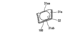
- FIG. 4 is a sectional view taken along line BB in FIG. 3.
- reference numeral 1 is an engine
- reference numeral 2 is a clutch
- reference numeral 3 is a transmission.
- the transmission 3 includes a bottomed cylindrical transmission case (accommodating case) 4, and an opening side end surface thereof is joined to a joining end surface of the clutch case 5 of the clutch 2.
- the transmission case 4 houses a series of gear groups 6 (not shown in FIG. 1, see FIG. 2), a rotating shaft 9 and the like (see FIG. 2) that support the gear groups 6, and the series of gears.
- the engine-side output is adjusted by the group 6, and the adjusted output is transmitted to the left and right drive shafts 8a, 8b via the differential gear 7.
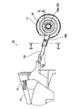
- the rotating shafts 9 have a main oil passage 10 and a plurality of branch oil passages 11 as shown in FIGS.
- the rotary shaft 9 has its axial direction oriented in the mission case axial direction (left and right in FIG. 1), and the main oil passage 10 of the rotary shaft 9 has a shaft end face.
- Each branch oil passage 11 extends radially outward from the main oil passage 10 and is opened to the outside from the outer peripheral surface of the rotary shaft 9.
- reference numeral 14 denotes a bearing that rotatably supports the end of the rotating shaft 9.
- a lubricating oil collecting guide 15 made of resin (for example, 6-6 nylon) is disposed in the mission case 4.
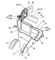
- the lubricating oil collection guide 15 includes an oil collection container 16, an oil funnel 17 as a guide member, and an oil passage member 18 that connects the oil collection container 16 and the oil funnel 17.
- the oil collecting container 16 has a long box shape as shown in FIG. 2, and the upper part thereof is opened with an upper opening 19 having a relatively large area.
- the oil collecting container 16 is disposed above the series of gear groups 6 in the mission case 4 with its longitudinal direction (left and right direction in FIG. 1) oriented in the axial direction of the mission case 4, and its upper opening 19. Is configured to accept as much as possible the lubricating oil (indicated by the arrow in FIG. 2) splashed by the rotation of the series of gear groups 6.
- the oil collection container 16 has a first collection container part 16A and a second collection container part 16B adjacent to each other, and each of the collection container parts 16A and 16B has collected lubrication. It plays a role of supplying oil to predetermined portions.
- first and second support plate portions 20 and 21 are integrally provided at one end portion in the longitudinal direction of the oil collecting container 16.
- the first support plate portion 20 has a flat plate shape and projects outward from the side surface of the oil collection container 16 toward one side in the width direction of the oil collection container 16 (downward in the vertical direction in FIG. 1).
- the plate surface of the first support plate portion 20 is directed in the longitudinal direction of the oil collection container 16.
- a plurality of press-fit pin portions 22 are integrally provided on the front surface of the first support plate portion 20 (the surface on the other end side in the longitudinal direction of the oil collecting container 16) as shown in FIG.
- the press-fit pin portion 22 protrudes from the front surface of the first support plate portion 20 toward the front side (the other end in the longitudinal direction of the oil collecting container 16).
- a known brush clip shape is used as the press-fit pin portion 22.
- the press-fit pin portion 22 is press-fitted into a press-fit hole (not shown) in the opening side end surface (flange portion surface or boss surface) of the mission case 4 corresponding to the press-fit pin portion 22. Is carried out until it comes into contact with the opening side end face of the mission case 4.
- the first support plate portion 20 is accommodated in a recess (not shown) formed in the clutch case 5 when the opening side end surface of the transmission case 4 and the joint end surface of the clutch case 5 are joined.
- the bottom surface of the recess restricts the first support plate portion 20 from moving to the back side (the side opposite to the press-fit pin portion 22).
- the press-fit pin portion 22, the press-fit hole, the first support plate portion 20, and the like are appropriately determined in consideration of the arrangement position, shape, and the like of the oil collection container 16.
- the second support plate portion 21 is protruded from the one end side surface in the longitudinal direction of the oil collecting container 16 toward the outside in the longitudinal direction as a flat protrusion.
- the plate surface of the second support plate portion 21 is directed in the vertical direction, and the second support plate portion 21 is held by a holding portion (not shown) of the clutch case 5.
- a bowl-shaped passage member 23 is integrally provided at the other longitudinal end of the oil collecting container 16.
- the passage member 23 is directed downward from the lower part of the first collection container part 16A toward the other end side in the longitudinal direction of the oil collection container 16 so as to guide the lubricating oil of the first collection container part 16A to a predetermined location.
- the lower end portion (outflow end portion) of the passage member 23 is supported by a support portion (not shown) in the mission case 4.
- the lubricating oil that has flowed out of the passage member 23 is supplied to a guide passage (not shown) that is formed on the inner wall of the mission case 4 and leads to a predetermined location.
- reference numeral 24 denotes a passage member for guiding the lubricating oil in the second collection container portion 16 ⁇ / b> B to one end side in the longitudinal direction of the oil collection container 16.
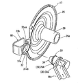
- the oil funnel 17 integrally includes a dish-shaped disc portion 25 and a cylindrical portion 26 protruding from the radial center of the inner surface of the disc portion 25.
- An introduction port 27 is opened at a central portion in the radial direction of the disc portion 25, and the outer surface side of the disc portion and the inside of the cylindrical portion 26 communicate with each other through the introduction port 27.
- the cylindrical portion 26 communicates the inside with the outside through the opening of the tip, and the outer diameter of the cylindrical portion is reduced more than the inner diameter of the main oil passage throughout.
- the oil funnel 17 is press-fitted and held in a recess 28 formed in the mission case bottom 4a with the cylindrical portion 26 facing inward in the axial direction of the mission case.
- the recess 28 is offset with respect to the oil collection container 16 on the outer side in the width direction of the oil collection container 16 (upper side in FIG. 1), and the first collection container portion 16A of the oil collection container 16 is provided. Although the position is lower than the bottom, the recess 28 is opposed to the shaft end surface 9a of the rotary shaft 9 having the main oil passage 10 and the like. Thereby, the cylinder part 26 of the oil funnel 17 (disk part 25) press-fitted and held in the recess 28 is inserted into the main oil passage 10 of the rotating shaft 9, and the cylinder part of the oil funnel 17 is inserted. A gap is formed between the outer periphery of 26 and the inner periphery of the main oil passage 10. For this reason, the rotating shaft 9 is rotatable regardless of the presence of the cylindrical portion 26.
- the oil passage member 18 has a first passage member 18A and a second passage member 18B, as shown in FIGS.
- both of the passage members 18A and 18B are formed in a bowl shape whose upper end is open, and the first passage member 18A is longer than the second passage member 18B.
- the first passage member 18A has both one end and the other end opened.
- the other end of the first passage member 18A is integrally connected to a portion of the second collection container portion 16B of the oil collection container 16 that faces the mission case bottom 4a, and the other end opening is the second collection container portion. It is opened near the bottom surface in 16B.
- One end side of the first passage member 18 ⁇ / b> A extends toward the oil funnel 17, and the one end side thereof is inclined downward toward the oil funnel 17. For this reason, the lubricating oil in the first collection container portion 16A flows toward one end side of the first passage member 18A based on gravity.
- the first passage member 18A is bent in the width direction (vertical direction in FIG.
- one end portion 29 of the first passage member 18A is a cylindrical end portion 29A, and the cylindrical end portion 29A is connected to the side wall portion 30a of the bowl-shaped bent portion 30, and the cylindrical shape
- the internal through hole of the end portion 29 ⁇ / b> A communicates with the hook-shaped bent portion 30.
- the front end surface of the bending part 30 is obstruct
- the second passage member 18B has one end closed and the other end opened.
- the second passage member 18B has a short length from the disk portion 25 of the oil funnel 17 and extends toward the oil collecting container 16 along the mission case bottom portion 4a, and one side wall portion 31a at the other end. Is continuous with the side part of the disk part 25, and the other side wall part 31b at the other end is arranged without being connected to any member on the outer surface side of the disk part 25 rather than the one side wall part 31a. Yes.
- the width of the pair of side wall portions 31a and 31b is narrower on the side closer to the disc portion 25 than on the far side.
- an insertion hole 32 is formed on one end side of the second passage member 18B.
- the insertion hole 32 is formed as a long hole as a loose fitting hole, and the major axis direction thereof is directed to the extending direction of the second passage member 18B.
- the short axis length of the insertion hole 32 is substantially the same as the diameter of the cylindrical end portion 29A of the first passage member 18A, and the long axis length of the insertion hole 32 is sufficiently larger than the diameter of the cylindrical end portion 29A.
- the upper portion 31aa of the insertion hole 32 is made thinner than the lower portion 31ab of the insertion hole 32 at the portion where the insertion hole 32 exists, and the upper portion 31aa is flexible. Have.
- a cylindrical end portion 29A of the first passage member 18A is inserted into the insertion hole 32 of the second passage member 18B so as to be movable in the axial direction thereof.
- interval of the side wall part 31a and the side wall part 31b is set from the point which ensures the displacement motion.
- the cylindrical end portion 29 ⁇ / b> A is relatively rotatable with respect to the insertion hole 32 and is slidable in the major axis direction of the insertion hole 32.
- the oil collection container 16 and the oil funnel 17 can ensure the relative displacement movement in the axial direction of the rotating shaft 9 by the forward and backward movement of the cylindrical end portion 29A with respect to the insertion hole 32 (in the second passage member 18B).
- a relative displacement movement in the radial direction of the rotary shaft 9 can be secured.
- a diameter-enlarged portion 33 is provided on the outer periphery of the tip end portion of the cylindrical end portion 29A as a retaining portion.
- the enlarged diameter portion 33 is formed over the entire circumference of the cylindrical end portion 29 ⁇ / b> A, for example, as a bulge shape, and the outer diameter thereof is longer than the short axis length of the insertion hole 32.
- the enlarged diameter portion 33 is disposed in the second passage member 18B as the cylindrical end portion 29A is inserted into the insertion hole 32.
- the interval between the enlarged diameter portion 33 and the side wall portion 30a of the bent portion 30 facing the enlarged diameter portion 33 is sufficiently longer than the thickness of the side wall portion 31a of the second passage member 18B.
- the cylindrical end portion 29A can enter the second passage member 18B until the peripheral edge portion of the insertion hole 32 abuts on the side wall portion 30a of the bent portion 30, and the cylindrical end portion 29A has its axial direction. Can be displaced sufficiently.
- the side wall 31b of the second passage member 18B is sufficiently separated from the side wall 31a in consideration of this.
- a guide wall portion 34 is provided on the thick end surface of the cylindrical end portion 29A of the first passage member 18A so as to protrude from the end surface.
- the guide wall portion 34 is disposed in the second passage member 18B so as to suppress the lubricating oil from flowing to the one end side of the second passage member 18B rather than the first passage member 18A.
- the guide wall portion 34 is formed over a substantially half circumference on one end side of the second passage member 18B with reference to the axis of the cylindrical end portion 29A.
- the length between the pair of side wall portions 31a and 31b of the second passage member 18B is the same as that between the pair of side wall portions 31a and 31b.
- 29A is a length that can be displaced.
- Such a lubricating oil collection guide 15 is assembled in the mission case 4 as follows. When assembled, the mission case 4 is in a state before the series of gear groups 6 and the like are accommodated, and the oil funnel of the lubricating oil collecting guide 15 is placed in the recess 28 of the bottom 4a in the mission case 4. 17 is press-fitted, and the press-fit pin portion 22 of the first support plate 20 in the oil collecting container 16 is press-fitted into a press-fit hole (not shown) in the opening side end surface (flange surface or boss surface) of the mission case 4. .
- the first and second passage members 18A and 18B are connected, but the cylindrical end portion 29A of the first passage member 18A has its axis line with respect to the insertion hole 32 (long hole) of the second passage member 18B.
- the oil collection container 16 and the oil funnel 17 can be displaced in the longitudinal direction of the oil collection container 16 (in the direction of the axis of the rotary shaft 9).
- the cylindrical end portion 29A can be changed in the long axis direction of the insertion hole 32 with respect to the insertion hole 32 (long hole) of the member 18B, and can be rotated about the axis of the cylindrical end portion 29A.
- the oil collecting container 16 and the oil funnel 17 can be relatively displaced in the radial direction of the oil funnel 17 (disk portion 25).
- the lubricating oil collection guide 15 becomes larger, a variation in dimensions occurs in the lubricating oil collection guide 15, and even if a variation in the dimensions is assembled in the mission case (recess 28). And press-fitting the disc portion 25 of the oil funnel 17 and press-fitting the press-fit pin portion 22 into the press-fitting hole in the opening side end surface (flange portion surface or boss surface) of the transmission case 4), and the first passage member 18A described above Due to the connection relationship with the second passage member 18B, the deformation force based on the dimensional variation is absorbed, and the oil collecting container 16 and the oil funnel 17 are not deformed, such as being relatively twisted. . As a result, the lubricating oil collection guide 15 is assembled in the mission case according to the standard. When this assembly is completed, a series of gear groups 6 and the like are housed in the mission case 4 and joined to the clutch case 5.
- the lubricating oil collection guide 15 realizes a lubricating oil circulation structure with a predetermined performance in the mission case 4.
- the second collection container portion 16B oil collection container 16 collects the lubricating oil that is spun up by a series of gear groups, and the lubricating oil is supplied to the oil funnel 17 via the first and second passage members 18A and 18B. Is supplied to the outer surface side.
- the lubricating oil adhering (supplied) to the outer surface side of the oil funnel 17 is drawn into the main oil passage 10 through the cylindrical portion 26 by the suction action based on the rotation of the rotating shaft 9, and the lubricating oil is The oil is sent out from the branch oil passage 11 radially outward of the rotary shaft 9 and is used again for lubricating the series of gear groups 6.
- the present invention includes the following aspects.
- (1) The other end of the second passage member 18B is connected to the oil collection container 16 (second collection container portion 16B), and the other end of the first passage member 18A is connected to the oil funnel 17.
- (2) The insertion hole 32 is generally loosely fitted to the cylindrical end portion 29A.
- the first and second passage members 18 ⁇ / b> A and 18 ⁇ / b> B are not limited to the bowl-shaped ones, but use tubular ones.
Landscapes
- Engineering & Computer Science (AREA)
- General Engineering & Computer Science (AREA)
- Mechanical Engineering (AREA)
- General Details Of Gearings (AREA)
Abstract
Description
前記オイル通路部材は、一端及び他端の両方が開口された第1通路部材と、一端が閉塞され他端が開口された第2通路部材と、を有し、
前記第2通路部材の一端側側壁部に挿通孔が形成され、
前記第1通路部材の一端部が前記挿通孔に進退動可能に挿通されて該第1通路部材の一端開口が前記第2通路部材内に位置されていると共に、該挿通孔に対して該第1通路部材の一端部が遊嵌状態とされ、
前記第1,第2通路部材のいずれか一方の他端開口が、前記オイル収集容器内に連通され、
前記第1,第2通路部材の他方の他端開口が、前記案内部材に連通され、
前記オイル収集容器と前記案内部材とが、前記挿入孔に対する前記第1通路部材の進退動及び遊嵌関係に基づき、前記回転軸の軸線方向及び径方向に相対的に変位動可能とされている構成とされている。
図1において、符号1はエンジン、符号2はクラッチ、符号3は変速機である。変速機3は、有底筒状のミッションケース(収容ケース)4を備えており、その開口側端面はクラッチ2のクラッチケース5の接合端面に接合されている。このミッションケース4内には一連のギヤ群6(図1では図示略、図2参照)、そのギヤ群6を支持する回転軸9等(図2参照)が収納されており、その一連のギヤ群6によりエンジン側出力が調整され、その調整された出力がディファレンシャルギア7を経て左右のドライブシャフト8a,8bに伝達される。上記回転軸9には、図2,図4に示すように、主オイル通路10、複数の分岐オイル通路11を有するものがある。この回転軸9は、他の回転軸9同様、その軸線方向がミッションケースの軸線方向(図1中、左右方向)に向けられており、その回転軸9の主オイル通路10は、その軸端面9aからその軸線方向内方に向けて延ばされ、各分岐オイル通路11は、主オイル通路10から径方向外方に延びて回転軸9の外周面から外部に開口されている。尚、図4中、符号14は回転軸9の端部を回転可能に支持する軸受けである。
第1支持板部20は、平板状をもって、オイル収集容器16の側面から該オイル収集容器16の幅方向一方側(図1中、上下方向下側)外方に向けて張り出されており、その第1支持板部20の板面はオイル収集容器16の長手方向に向けられている。この第1支持板部20の前面(オイル収集容器16の長手方向他端側の面)には、図2に示すように、複数の圧入ピン部22が一体的に設けられている。この圧入ピン部22は、第1支持板部20の前面から前方(オイル収集容器16の長手方向他端側)に向けて突出されており、本実施形態においては、この圧入ピン部22として、既知のブラッシュクリップ形状のものが用いられている。この圧入ピン部22は、それに対応したミッションケース4の開口側端面(フランジ部面或いはボス面)における圧入孔(図示略)に圧入されており、その圧入は、第1支持板部20の前面がミッションケース4の開口側端面に当接するまで行われる。また、第1支持板部20は、ミッションケース4の開口側端面とクラッチケース5の接合端面との接合に伴い、クラッチケース5に形成された凹所内(図示略)に収納されることになっており、その凹所底面により第1支持板部20はその背面側(圧入ピン部22と反対側)に移動することが規制されている。尚、この圧入ピン部22、圧入孔、第1支持板部20等は、オイル収集容器16の配置位置、形状等を考慮して適宜決められる。
尚、図2中、符号24は、第2収集容器部16B内の潤滑オイルをオイル収集容器16の長手方向一端側に導くための通路部材である。
組付けに際しては、ミッションケース4内が一連のギヤ群6等を収納する前の状態となっており、そのミッションケース4内における底部4aの凹所28内に潤滑オイル収集案内具15のオイルファンネル17が圧入されると共に、オイル収集容器16における第1支持板部20の圧入ピン部22がミッションケース4の開口側端面(フランジ部面或いはボス面)における圧入孔(図示略)に圧入される。
このとき、第1,第2通路部材18A,18Bが連結されているが、第2通路部材18Bの挿通孔32(長孔)に対して第1通路部材18Aの円筒形状端部29Aがその軸線方向に変位動可能とされることにより、オイル収集容器16とオイルファンネル17とが、オイル収集容器16の長手方向(回転軸9の軸線方向)に変位動可能とされ、さらには、第2通路部材18Bの挿通孔32(長孔)に対して円筒形状端部29Aが挿通孔32の長軸方向に変動可能とされると共に該円筒形状端部29Aの軸線を中心として回動可能とされることにより、オイル収集容器16とオイルファンネル17とが、相対的に該オイルファンネル17(円板部25)の径方向に変位動可能とされている。
この組付けが終えると、ミッションケース4内に一連のギヤ群6等が収納され、クラッチケース5との接合が行われる。
(1)第2通路部材18Bの他端をオイル収集容器16(第2収集容器部16B)に接続し、第1通路部材18Aの他端をオイルファンネル17に接続すること。
(2)挿通孔32が、円筒形状端部29Aに対して全体的に遊嵌状態であるものであること。
(3)挿通孔32との遊嵌状態が確保できる限り、第1通路部材18Aの一端部は、円筒形状のものに限られないこと。
(4)第1,第2通路部材18A,18Bが、樋状のものに限らず、管状のもの等を用いること。
Claims (8)
- 動力伝達要素として一連のギヤ、回転軸を収容する収容ケース内において、該一連のギヤ上方に配置されて該ギヤの回転により跳ね上げられたオイルを受け入れるオイル収集容器と、前記収容ケース内における回転軸の軸端面に対向して配設されて該回転軸の軸端面に開口されたオイル通路内に潤滑オイルを案内する案内部材と、該案内部材と前記オイル収集容器とを連絡して該オイル収集容器が収集した潤滑オイルを該案内部材に導くオイル通路部材と、が備えられている潤滑オイル収集案内具において、
前記オイル通路部材は、一端及び他端の両方が開口された第1通路部材と、一端が閉塞され他端が開口された第2通路部材と、を有し、
前記第2通路部材の一端側側壁部に挿通孔が形成され、
前記第1通路部材の一端部が前記挿通孔に進退動可能に挿通されて該第1通路部材の一端開口が前記第2通路部材内に位置されていると共に、該挿通孔に対して該第1通路部材の一端部が遊嵌状態とされ、
前記第1,第2通路部材のいずれか一方の他端開口が、前記オイル収集容器内に連通され、
前記第1,第2通路部材の他方の他端開口が、前記案内部材に連通され、
前記オイル収集容器と前記案内部材とが、前記挿入孔に対する前記第1通路部材の進退動及び遊嵌関係に基づき、前記回転軸の軸線方向及び径方向に相対的に変位動可能とされている、
ことを特徴とする潤滑オイル収集案内具。 - 請求項1において、
前記挿通孔が、前記第2通路部材の延び方向に長く延びる長孔とされ、
前記第1通路部材の一端部が円筒形状端部とされ、
前記円筒形状端部が、前記長孔に対して相対的に回動可能且つ該長孔の長軸方向に摺動可能とされている、
ことを特徴とする潤滑オイル収集案内具。 - 請求項2において、
前記円筒形状端部の先端部外周に、抜け止め部として、該円筒形状端部の外径よりも拡径された拡径部が設けられ、
前記拡径部の外径が、前記長孔の短軸方向長さより長くされている、
ことを特徴とする潤滑オイル収集案内具。 - 請求項3において、
前記拡径部と前記円筒形状端部の軸線方向内端との間の距離が、前記第2通路部材の一端側側壁部の肉厚よりも長くされている、
ことを特徴とする潤滑オイル収集案内具。 - 請求項3において、
前記第2通路部材が、上方が開口する樋形状に形成され、
前記第2通路部材の側壁部は、前記長孔が存在する個所において、該長孔の下側部分よりも上側部分が薄くされて、該上側部分が可撓性を有している、
ことを特徴とする潤滑オイル収集案内具。 - 請求項1において、
前記第1通路部材の一端部の先端部外周に抜け止め部が、前記挿通孔の周縁部に臨むように突設されている、
ことを特徴とする潤滑オイル収集案内具。 - 請求項1又は2において、
前記第1通路部材の一端部端面に、該端面から張り出すようにして案内壁部が設けられ、
前記案内壁部は、前記第2通路部材内において、潤滑オイルが前記第1通路部材よりも該第2通路部材の一端側に流れることを抑制するように配置されている、
ことを特徴とする潤滑オイル収集案内具。 - 請求項1~7のいずれか1項において、
前記第1通路部材の他端開口が、前記オイル収集容器内に連通され、
前記第2通路部材の他端開口が、前記案内部材に連通されている、
ことを特徴とする潤滑オイル収集案内具。
Priority Applications (3)
| Application Number | Priority Date | Filing Date | Title |
|---|---|---|---|
| US13/989,244 US8905192B2 (en) | 2010-11-26 | 2011-11-21 | Lubricating-oil collection guide tool |
| DE112011103935.2T DE112011103935B4 (de) | 2010-11-26 | 2011-11-21 | Anordnung zum Sammeln und Lenken von Schmieröl |
| CN201180056923.3A CN103403399B (zh) | 2010-11-26 | 2011-11-21 | 润滑油收集引导工具 |
Applications Claiming Priority (2)
| Application Number | Priority Date | Filing Date | Title |
|---|---|---|---|
| JP2010263246A JP5551573B2 (ja) | 2010-11-26 | 2010-11-26 | 潤滑オイル収集案内具 |
| JP2010-263246 | 2010-11-26 |
Publications (1)
| Publication Number | Publication Date |
|---|---|
| WO2012070545A1 true WO2012070545A1 (ja) | 2012-05-31 |
Family
ID=46145887
Family Applications (1)
| Application Number | Title | Priority Date | Filing Date |
|---|---|---|---|
| PCT/JP2011/076831 Ceased WO2012070545A1 (ja) | 2010-11-26 | 2011-11-21 | 潤滑オイル収集案内具 |
Country Status (5)
| Country | Link |
|---|---|
| US (1) | US8905192B2 (ja) |
| JP (1) | JP5551573B2 (ja) |
| CN (1) | CN103403399B (ja) |
| DE (1) | DE112011103935B4 (ja) |
| WO (1) | WO2012070545A1 (ja) |
Cited By (1)
| Publication number | Priority date | Publication date | Assignee | Title |
|---|---|---|---|---|
| CN109073069A (zh) * | 2016-04-15 | 2018-12-21 | 标致雪铁龙汽车股份有限公司 | 空心轴润滑回路 |
Families Citing this family (26)
| Publication number | Priority date | Publication date | Assignee | Title |
|---|---|---|---|---|
| JP5966997B2 (ja) * | 2013-03-29 | 2016-08-10 | マツダ株式会社 | 変速機の潤滑構造 |
| JP6233013B2 (ja) * | 2013-12-26 | 2017-11-22 | アイシン・エィ・ダブリュ株式会社 | 動力伝達装置 |
| US9500274B2 (en) * | 2014-04-28 | 2016-11-22 | Kawasaki Jukogyo Kabushiki Kaisha | Transmission apparatus |
| DE102014111461B4 (de) * | 2014-08-12 | 2024-07-18 | Dr. Ing. H.C. F. Porsche Aktiengesellschaft | Ölfangvorrichtung und Getriebe mit einer solchen Ölfangvorrichtung |
| DE102014218439A1 (de) * | 2014-09-15 | 2016-03-17 | Volkswagen Aktiengesellschaft | Leitmittel zur Anordnung im Bereich eines Getriebes und/oder einer Kupplung eines Kraftfahrzeuges |
| JP6639328B2 (ja) * | 2016-05-25 | 2020-02-05 | トヨタ自動車株式会社 | 動力伝達装置の潤滑構造 |
| CN106015535A (zh) * | 2016-06-17 | 2016-10-12 | 柳州上汽汽车变速器有限公司 | 汽车变速器润滑系统 |
| JP6452747B2 (ja) * | 2017-03-29 | 2019-01-16 | 本田技研工業株式会社 | 油圧供給構造体 |
| CN107701708A (zh) * | 2017-11-17 | 2018-02-16 | 金陵科技学院 | 一种变速器用精准施加润滑油辅助结构 |
| JP6612903B2 (ja) * | 2018-01-12 | 2019-11-27 | 本田技研工業株式会社 | ローリングベアリングの潤滑構造 |
| JP6705855B2 (ja) * | 2018-03-14 | 2020-06-03 | 本田技研工業株式会社 | 変速機の潤滑油供給構造 |
| EP3569896B1 (en) | 2018-05-14 | 2021-08-11 | Ningbo Geely Automobile Research & Development Co. Ltd. | A transmission |
| US11739825B2 (en) | 2019-03-12 | 2023-08-29 | Sew-Eurodrive Gmbh & Co. Kg | Transmission comprising a housing and an oil distribution part arranged in the housing |
| JP2021038821A (ja) * | 2019-09-04 | 2021-03-11 | 明石機械工業株式会社 | 変速機の潤滑構造 |
| JP7300940B2 (ja) * | 2019-09-04 | 2023-06-30 | 明石機械工業株式会社 | 変速機の潤滑構造 |
| DE102019215554A1 (de) | 2019-10-10 | 2021-04-15 | Deere & Company | Schmierungsanordnung für ein Getriebe |
| KR102307705B1 (ko) * | 2019-12-10 | 2021-10-01 | 현대트랜시스 주식회사 | 자동변속기의 윤활장치 |
| FR3104660B1 (fr) * | 2019-12-17 | 2021-11-26 | Renault Sas | Procédé et dispositif de pilotage du refroidissement d'une boite de vitesses |
| KR102741908B1 (ko) * | 2020-02-24 | 2024-12-11 | 엘지마그나 이파워트레인 주식회사 | 기어 시스템 |
| JP7537267B2 (ja) * | 2020-12-18 | 2024-08-21 | ニデック株式会社 | 動力伝達装置、モータユニット、及び車両 |
| JP7671158B2 (ja) * | 2021-03-08 | 2025-05-01 | ニデック株式会社 | 伝達機構装置および駆動装置 |
| DE102021213489A1 (de) | 2021-11-30 | 2023-06-01 | Robert Bosch Gesellschaft mit beschränkter Haftung | Ölführungskanalteil für den Einbau in ein Getriebe |
| DE102021213485A1 (de) * | 2021-11-30 | 2023-06-01 | Robert Bosch Gesellschaft mit beschränkter Haftung | Getriebe mit einem Ölführungskanalteil |
| DE102021213491A1 (de) | 2021-11-30 | 2023-06-01 | Robert Bosch Gesellschaft mit beschränkter Haftung | Ölführungskanalteil für den Einbau in ein Getriebe und Getriebe mit einem Ölführungskanalteil |
| KR102696916B1 (ko) * | 2022-07-12 | 2024-08-19 | 현대트랜시스 주식회사 | 오일 가이드 장치 |
| JP2025024591A (ja) * | 2023-08-07 | 2025-02-20 | 本田技研工業株式会社 | 動力伝達装置 |
Citations (6)
| Publication number | Priority date | Publication date | Assignee | Title |
|---|---|---|---|---|
| JPS59136328U (ja) * | 1983-03-04 | 1984-09-11 | 本田技研工業株式会社 | 自動車用変速機のオイルガイド固定構造 |
| JPS59186554U (ja) * | 1983-05-31 | 1984-12-11 | 日産自動車株式会社 | トランスアクスルのオイルガ−タ取付構造 |
| JPS60123456U (ja) * | 1984-01-27 | 1985-08-20 | トヨタ自動車株式会社 | 歯車変速機における潤滑機構 |
| JPS6192363A (ja) * | 1984-10-09 | 1986-05-10 | Honda Motor Co Ltd | 自動車用変速機における給油装置 |
| JP2003329113A (ja) * | 2002-05-15 | 2003-11-19 | Aichi Mach Ind Co Ltd | 手動変速機の油潤滑機構 |
| JP2004052904A (ja) * | 2002-07-19 | 2004-02-19 | Fuji Heavy Ind Ltd | 車両用変速機の潤滑油供給構造 |
Family Cites Families (21)
| Publication number | Priority date | Publication date | Assignee | Title |
|---|---|---|---|---|
| US3785458A (en) * | 1972-04-14 | 1974-01-15 | Caterpillar Tractor Co | Lubrication system for a gear drive mechanism |
| JPS5455261A (en) * | 1977-10-12 | 1979-05-02 | Toyota Motor Corp | Lubricant induction unit for gear transmission |
| JPS57140964A (en) * | 1981-02-20 | 1982-08-31 | Nissan Motor Co Ltd | Lubrication mechanism for transfer axle |
| US4987974A (en) * | 1989-12-11 | 1991-01-29 | Saturn Corporation | Device to assist with the radial distribution of lubricating fluid from a rotating shaft |
| JPH04277360A (ja) | 1991-02-28 | 1992-10-02 | Suzuki Motor Corp | 歯車変速機における潤滑構造 |
| JPH04277361A (ja) | 1991-02-28 | 1992-10-02 | Suzuki Motor Corp | 歯車変速機における潤滑構造 |
| US5154517A (en) * | 1991-04-17 | 1992-10-13 | Ina Bearing Company, Inc. | Anti-friction bearing with integral oil feed tube |
| JPH0712655A (ja) | 1993-06-29 | 1995-01-17 | Toshiba Corp | 測定システム |
| JP3141970B2 (ja) | 1993-06-30 | 2001-03-07 | ソマール株式会社 | 液状エポキシ樹脂組成物 |
| JPH0712655U (ja) | 1993-08-09 | 1995-03-03 | 愛知機械工業株式会社 | 潤滑構造 |
| JPH0718061U (ja) | 1993-09-03 | 1995-03-31 | 愛知機械工業株式会社 | 潤滑構造 |
| JP5429104B2 (ja) | 1998-12-28 | 2014-02-26 | 日立化成株式会社 | 金属用研磨液及びそれを用いた研磨方法 |
| KR20010064104A (ko) * | 1999-12-24 | 2001-07-09 | 이계안 | 수동 변속기의 윤활 오일 안내 장치 |
| JP2001200988A (ja) * | 2000-01-17 | 2001-07-27 | Honda Motor Co Ltd | 油供給装置 |
| US7022039B2 (en) * | 2003-09-11 | 2006-04-04 | Komatsu America Corp. | Lubrication system for planetary transmission |
| JP4039351B2 (ja) * | 2003-10-16 | 2008-01-30 | トヨタ自動車株式会社 | 車両用のオイル供給装置 |
| JP4500177B2 (ja) * | 2005-02-21 | 2010-07-14 | アイシン・エーアイ株式会社 | 変速機 |
| BE1016742A3 (nl) * | 2005-08-31 | 2007-05-08 | Hansen Transmissions Int | Een planetaire tandwielconstrucie. |
| DE102006055808B4 (de) * | 2006-11-27 | 2008-08-21 | Gkn Driveline International Gmbh | Ölschöpfanordnung zur Ölversorgung von zueinander drehenden Maschinenbauteilen |
| JP4894839B2 (ja) | 2008-10-08 | 2012-03-14 | トヨタ自動車株式会社 | 動力伝達装置の潤滑構造 |
| JP5336287B2 (ja) * | 2009-07-27 | 2013-11-06 | 株式会社ニフコ | 潤滑オイル収集案内具 |
-
2010
- 2010-11-26 JP JP2010263246A patent/JP5551573B2/ja not_active Expired - Fee Related
-
2011
- 2011-11-21 WO PCT/JP2011/076831 patent/WO2012070545A1/ja not_active Ceased
- 2011-11-21 US US13/989,244 patent/US8905192B2/en not_active Expired - Fee Related
- 2011-11-21 DE DE112011103935.2T patent/DE112011103935B4/de not_active Expired - Fee Related
- 2011-11-21 CN CN201180056923.3A patent/CN103403399B/zh not_active Expired - Fee Related
Patent Citations (6)
| Publication number | Priority date | Publication date | Assignee | Title |
|---|---|---|---|---|
| JPS59136328U (ja) * | 1983-03-04 | 1984-09-11 | 本田技研工業株式会社 | 自動車用変速機のオイルガイド固定構造 |
| JPS59186554U (ja) * | 1983-05-31 | 1984-12-11 | 日産自動車株式会社 | トランスアクスルのオイルガ−タ取付構造 |
| JPS60123456U (ja) * | 1984-01-27 | 1985-08-20 | トヨタ自動車株式会社 | 歯車変速機における潤滑機構 |
| JPS6192363A (ja) * | 1984-10-09 | 1986-05-10 | Honda Motor Co Ltd | 自動車用変速機における給油装置 |
| JP2003329113A (ja) * | 2002-05-15 | 2003-11-19 | Aichi Mach Ind Co Ltd | 手動変速機の油潤滑機構 |
| JP2004052904A (ja) * | 2002-07-19 | 2004-02-19 | Fuji Heavy Ind Ltd | 車両用変速機の潤滑油供給構造 |
Cited By (1)
| Publication number | Priority date | Publication date | Assignee | Title |
|---|---|---|---|---|
| CN109073069A (zh) * | 2016-04-15 | 2018-12-21 | 标致雪铁龙汽车股份有限公司 | 空心轴润滑回路 |
Also Published As
| Publication number | Publication date |
|---|---|
| JP2012112482A (ja) | 2012-06-14 |
| US8905192B2 (en) | 2014-12-09 |
| CN103403399A (zh) | 2013-11-20 |
| US20130283955A1 (en) | 2013-10-31 |
| CN103403399B (zh) | 2016-10-12 |
| JP5551573B2 (ja) | 2014-07-16 |
| DE112011103935T5 (de) | 2013-08-22 |
| DE112011103935B4 (de) | 2019-05-29 |
Similar Documents
| Publication | Publication Date | Title |
|---|---|---|
| JP5551573B2 (ja) | 潤滑オイル収集案内具 | |
| US7841961B2 (en) | Planetary gearset | |
| JP5302115B2 (ja) | ラチェット | |
| US20140287864A1 (en) | Pinion lubrication structure of planetary gear mechanism | |
| CN211624163U (zh) | 混合动力车辆用驱动装置的润滑结构 | |
| US20160076636A1 (en) | Power transmission device | |
| CN102168749A (zh) | 车辆动力传递装置 | |
| CN107202079A (zh) | 用于湿式双离合器的液压控制系统 | |
| KR20080048004A (ko) | 서로 상대 회전하는 기계장치 부품들의 오일 공급용 오일스쿠프 장치 | |
| KR20140022045A (ko) | 유성 기어 캐리어용 오일 수집 링 디스크 | |
| JP2009286188A (ja) | 動力伝達装置 | |
| CN211649015U (zh) | 混合动力车辆用驱动装置的润滑结构 | |
| US20060065488A1 (en) | Lubricating structure of planetary gear mechanism | |
| CN112739937B (zh) | 车辆用驱动装置 | |
| JP7424041B2 (ja) | 駆動装置 | |
| CN208010895U (zh) | 车辆和缓冲器 | |
| JP7501301B2 (ja) | キャッチタンクの組付け構造 | |
| CN100353092C (zh) | 手动换档变速器的润滑结构 | |
| CN114370492B (zh) | 车辆的变速箱 | |
| US10087997B2 (en) | Clutch and motor | |
| JP7321950B2 (ja) | 動力伝達装置 | |
| JP4511230B2 (ja) | 可変プーリ装置 | |
| JP2010096333A (ja) | 潤滑装置およびそれを備えた変速機 | |
| JP7647158B2 (ja) | 回転電機および駆動装置 | |
| KR20210073625A (ko) | 자동변속기의 윤활장치 |
Legal Events
| Date | Code | Title | Description |
|---|---|---|---|
| 121 | Ep: the epo has been informed by wipo that ep was designated in this application |
Ref document number: 11843723 Country of ref document: EP Kind code of ref document: A1 |
|
| WWE | Wipo information: entry into national phase |
Ref document number: 112011103935 Country of ref document: DE Ref document number: 1120111039352 Country of ref document: DE |
|
| WWE | Wipo information: entry into national phase |
Ref document number: 13989244 Country of ref document: US |
|
| 122 | Ep: pct application non-entry in european phase |
Ref document number: 11843723 Country of ref document: EP Kind code of ref document: A1 |