WO2012067043A1 - 回転電機のロータコア - Google Patents
回転電機のロータコア Download PDFInfo
- Publication number
- WO2012067043A1 WO2012067043A1 PCT/JP2011/076094 JP2011076094W WO2012067043A1 WO 2012067043 A1 WO2012067043 A1 WO 2012067043A1 JP 2011076094 W JP2011076094 W JP 2011076094W WO 2012067043 A1 WO2012067043 A1 WO 2012067043A1
- Authority
- WO
- WIPO (PCT)
- Prior art keywords
- core
- core plate
- caulking
- width
- rotor core
- Prior art date
Links
Images


Classifications
-
- H—ELECTRICITY
- H02—GENERATION; CONVERSION OR DISTRIBUTION OF ELECTRIC POWER
- H02K—DYNAMO-ELECTRIC MACHINES
- H02K1/00—Details of the magnetic circuit
- H02K1/06—Details of the magnetic circuit characterised by the shape, form or construction
- H02K1/22—Rotating parts of the magnetic circuit
- H02K1/27—Rotor cores with permanent magnets
- H02K1/2706—Inner rotors
- H02K1/272—Inner rotors the magnetisation axis of the magnets being perpendicular to the rotor axis
- H02K1/274—Inner rotors the magnetisation axis of the magnets being perpendicular to the rotor axis the rotor consisting of two or more circumferentially positioned magnets
- H02K1/2753—Inner rotors the magnetisation axis of the magnets being perpendicular to the rotor axis the rotor consisting of two or more circumferentially positioned magnets the rotor consisting of magnets or groups of magnets arranged with alternating polarity
- H02K1/276—Magnets embedded in the magnetic core, e.g. interior permanent magnets [IPM]
Definitions
- the present invention relates to a rotor core of a rotating electrical machine formed by laminating a plurality of core plates, and more particularly to a caulking structure thereof.
- a rotor core of a rotating electrical machine formed by laminating core plates punched out of electromagnetic steel sheets to reduce the generation of eddy currents is known.
- a rotor core in which a plurality of core plates (iron core blanks 9) are laminated, a circular caulking portion 16 is formed on the core plate 9 by a punch, and the laminated core plates are joined together.
- the thing which caulks by dowel caulking is devised (for example, refer patent document 1).
- a plurality of core plates are required. If the shape of the core plate is an annular shape, the core plate is removed from the base material. When punching, the center of the ring cannot be used, resulting in a low yield. Therefore, the core plate is formed by connecting a plurality of divided core plate pieces, and the core plates are laminated so that the phase (circumferential position) of the seam of the core plate pieces is shifted (so-called brick stacking). ) A rotor core may be formed (see Patent Document 2).
- the core plate pieces are bricked in this way to form the rotor core, and when the core plates are caulked together by dowel caulking, a rotor core having a high yield and capable of holding the shape alone can be formed. .
- JP 2010-142114 A Japanese Patent Laid-Open No. 2002-262496
- the caulking portion is directed toward the circumferential direction of the core plate based on the centrifugal force acting on each of the core plate pieces of each layer when the rotor core rotates. Strong stress is generated.
- the caulking portion of the circular shape causes tensile residual stress over the entire circumference, and the portion of the caulking portion where the stress is generated based on the centrifugal force causes the residual stress of the tensile force. Both stress and stress based on centrifugal force work.
- an object of the present invention is to provide a rotor core that solves the above problems by separating a portion that receives stress based on centrifugal force of a caulking portion and a portion that generates residual stress.
- the present invention is formed by laminating a plurality of annular core plates (2), and arc-shaped core plate pieces (3) obtained by equally dividing the core plate (2) are connected to form the core plate ( 2) and the circumferential position of the seams (D 1 , D 2 ) of the core plate pieces (3) is the stacking direction of the core plates (2) for each predetermined number of core plates.
- the core plate piece (3) is formed on one surface and at the end in the circumferential direction (C) is formed with a convex portion (11) formed in an arc shape, and on the other surface, the core plate Concave part (12) in which the end part in the circumferential direction (C) is formed in an arc shape while fitting with the convex part (11) of the core plate piece (3) of the other layer when (2) is laminated.
- the width (W r2 ) in the radial direction (R) of the core plate (2) of the convex portion (11) is the width (W r1 ) in the radial direction (R) of the core plate (2) of the concave portion (12).
- the fitting in the radial direction (R) of the convex portion (11) and the concave portion (12) is an interference fit
- the width (W c2 ) in the circumferential direction (C) of the core plate (2) of the convex portion (11) is the width in the circumferential direction (C) of the core plate (2) in the concave portion (12) ( Smaller than W c1 )
- the fitting in the circumferential direction of the convex portion (11) and the concave portion (12) was defined as a gap fitting. It is characterized by that.
- the fitting between the convex portion and the concave portion of the core plate piece is an interference fit in the radial direction of the core plate, so that the core plates can be fastened at the portion of the interference fit. I can do it.
- the fitting between the convex portion and the concave portion is a gap fitting with respect to a portion where a large stress is applied based on an attempt to move the core plate pieces away from each other by centrifugal force.
- the convex portions formed in the arc shape and the circumferential ends of the concave portions come into contact with each other. It can receive in the part which the residual stress of a convex part and a recessed part does not produce. Thereby, the strength of the caulking portion is improved, and even in the rotor core obtained by dividing the core plate, the necessary rotational strength can be achieved with a radially compact configuration.
- the core plate can be formed thin, eddy currents generated in the rotor core can be suppressed to a low level, and a rotating electrical machine with high yield and efficiency can be produced using the rotor core.
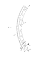
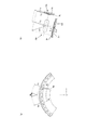
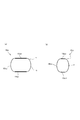
- the schematic diagram which shows the rotor core which concerns on the 1st Embodiment of this invention The schematic diagram which shows the core plate piece which concerns on the 1st Embodiment of this invention. It is a schematic diagram explaining the shape of the crimping part which concerns on the 1st Embodiment of this invention, Comprising: (a) The top view of a crimping part, (b) AA sectional drawing of a crimping part, (c) The crimping part BB sectional drawing.
- FIG.4 It is a schematic diagram explaining the residual stress applied to the crimping part of the core plate piece concerning the 1st Embodiment of this invention, Comprising: (a) The figure which shows the state before laminating
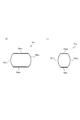
- FIG. 5 It is a schematic diagram explaining the stress based on the centrifugal force applied to the crimping part of the core plate piece which concerns on the 1st Embodiment of this invention, Comprising: (a) The schematic diagram explaining the centrifugal force which arises in the core plate piece of a different layer (B) The principal part enlarged view of Fig.5 (a). (A) The schematic diagram explaining the shape of the crimping part which concerns on the 2nd Embodiment of this invention, (b) The modification of Fig.6 (a). (A) The schematic diagram explaining the shape of the crimping part which concerns on the 3rd Embodiment of this invention, (b) The modification of Fig.7 (a).
- an interference fit refers to a fit of a type in which the width of the convex portion to be fitted is slightly larger than the width of the concave portion, and the gap fit is a gap between the convex portion and the concave portion. This means a type of fit with a predetermined gap.
- a rotor core 1 for an IPM motor (rotary electric machine) is formed by laminating a plurality of annular core plates 2.
- the core plate 2 is a plate-shaped member punched out from the base material of the electromagnetic steel plate, and in order to improve the yield, the arc-shaped core plate piece 3 that is equally divided (in this embodiment, divided into five). Are connected.
- one end portion of the core plate piece 3 is formed with a protruding portion 5a for connecting to the circumferentially adjacent core plate piece 3, and the other end portion is provided with the core plate piece.
- a fitting portion 5b into which the protruding portion 5a of the piece 3 is fitted is formed.
- joints D 1 and D 2 between these core plate pieces that is, the number of joints between the projections 5 a and the fitting portions 5 b are formed in the same number as the number of the core plate pieces 3.
- the core plate 2 is formed in an annular shape by connecting the core plate pieces 3 having the same shape to any one of the core plates 2, but the joint of the core plate pieces 3 with respect to the adjacent core plates 2 in the stacking direction. They are laminated by bricks that shift the positions (phases) of D 1 and D 2 in the circumferential direction C. That is, the positions in the circumferential direction C of the joints D 1 and D 2 of the core plate piece 3 are configured to be different between the core plates adjacent in the stacking direction.
- the even layer core plate piece 3 E has a joint D 1 whose core plate is an odd layer. It is provided so that the position in the circumferential direction C is deviated from the joint D 2 of the piece 3 O by a predetermined angle.
- the core plate piece 3 has a magnet insertion hole 6 into which a rare earth permanent magnet such as a neodymium magnet is inserted, and a caulking portion 10 for fastening the plurality of stacked core plates 2 to each other in the circumferential direction. A plurality are formed.
- the caulking portions 10 are respectively provided on the inner peripheral sides of both end portions of the magnet fitting insertion holes 6, and the rotor core 1 is connected to each core plate 2 by caulking the caulking portions 10 after the core plates 2 are temporarily assembled. The shape can be maintained without being separated.
- the caulking portion 10 includes a convex portion (a dowel) 11 in which a core plate piece is projected to one surface side by pressing, and the convex portion 11 is formed, thereby forming the core plate It is comprised from the recessed part 12 formed in the surface (other surface) on the opposite side to the convex part 11 of the piece 3, The convex part 11 of the other core plate piece 3 fits into this recessed part 12 As a result, dowels are caulked.
- a convex portion (a dowel) 11 in which a core plate piece is projected to one surface side by pressing, and the convex portion 11 is formed, thereby forming the core plate It is comprised from the recessed part 12 formed in the surface (other surface) on the opposite side to the convex part 11 of the piece 3,
- the convex part 11 of the other core plate piece 3 fits into this recessed part 12 As a result, dowels are caulked.
- the residual stress is a stress caused by the caulking portion 10 is interference fit
- a ⁇ C layer L A stacked together is shown in FIG. 4, L B, L C of the core plate pieces 3 A, 3 B, 3
- the caulking portion 10 is formed as in the portion 10a serving as the interference fit is greater than the width W r1 width W r2 is the interference d 1 minute only recess 12 of the protrusion 11 (See FIG. 4A).
- the core plate pieces 3 A , 3 B , 3 C are inserted into the concave portion 12 that is narrow by the tightening allowance d 1 so that the core plate pieces 3 A , 3 B , 3 C are While being connected to the stacking direction, as the core plate pieces 3 B of FIG. 4 (c), when the protrusion 11 is press-fitted into the core plate pieces 3 C recesses 12 of the other layer (C layer L C) , projections 11 that are press-fitted is subjected to a C layer L C stress Tc in the direction to compress the walls 12a of the recess 12 (direction toward the projections 11 of the C layer L C recess from B layer L B) of the.
- the stress based on the centrifugal force is a stress generated in the caulking portion 10 when the rotor core 1 rotates.
- the overlapping core plate pieces 3 E Centrifugal forces F E and F O act on 3 O , respectively.
- Centrifugal forces F E and F O acting on these overlapping core plate pieces 3 E and 3 O are converted into circumferential components F EX and F OX and radial components F EY and F OY of the core plate pieces 3 E and 3 O , respectively.
- the radial components F EY and F OY both act in the direction from the center of the core plate 2 toward the outer diameter side, the overlapping core plate pieces 3 E 1 and 3 O cannot receive each other's reaction force, and almost no force acts on the caulking portion 10 that connects the core plate pieces 3 E and 3 O of different layers.
- the circumferential direction components F OX , F EX of the centrifugal forces F E , F O have different directions of action between the overlapping core plate pieces 3 E , 3 O , so that these core plate pieces 3 E , 3 O are connected.
- the caulking portions 10 can receive reaction forces from each other. That is, when attention is focused on the caulking portion 10 P that is formed on the end portion of the core plate piece 3 E, by a core plate overlapping tends to move to the opposite side along the circumferential direction, the caulking portion 10 P, the core Stress based on centrifugal force is generated in the circumferential direction of the plate 2.
- the radial components F EY and F OY of the centrifugal forces F E and F O are distributed and received by the caulking portion of the entire core plate 2, and particularly near the joints D 1 and D 2 of the core plate piece 3. A large force acts on the crimped portion.
- the caulking portion 10 according to the present invention shown in FIG. 3 described above is configured so that the stress based on the centrifugal force and the residual stress of the tensile force do not occur in the same place, and the interference fit causes the residual stress.
- the portion 10a and the portion 10b where the stress due to the centrifugal force is generated are configured separately.
- the caulking portion 10 includes a linear portion 10a in which the wall portions 11a and 12a in the circumferential direction (tangential direction of the core plate piece 3) C of the convex portion 11 and the concave portion 12 are formed linearly.
- the wall portions 11b and 12b in the radial direction R of the core plate 2 of the convex portion 11 and the concave portion 12 are formed in an arc shape having a predetermined curvature, and the arc portion 10b is formed between the straight portions 10a.
- the straight part 10a forms a part that is an interference fit of the caulking part 10.
- the caulking portion 10 has a width W r2 in the radial direction R of the core plate 2 of the convex portion 11 which is a width between the linear wall portions 11a and 11a, and is a width between the linear wall portions 12a and 12a.
- the width W r1 of the concave portion 12 in the radial direction R of the core plate 2 is larger (W r2 > W r1 ), and the fitting of the convex portions 11 and the concave portion 12 in the radial direction R is an interference fit.
- the arc portion 10b which is the circumferential end portion of the convex portion 11 and the concave portion 12 has an arc shape. wall 11b of, and has a clearance fit with a predetermined gap d 2 between 12b. That is, the arc portion 10b forms a gap fitting portion of the caulking portion 10, and the width in the circumferential direction C of the core plate 2 of the convex portion 11 corresponding to the width between the arc-shaped wall portions 11b and 11b.
- W c2 is smaller than the circumferential width W c1 of the core plate 2 of the recess 12 corresponding to the width between the arcuate wall portions 12 b and 12 b (W c1 > W c2 ).
- the arcuate wall portion 11b and the arcuate wall portion 12b of the recess 12 are formed so as to be in contact with each other. In other words, during rotation of the rotor core 1 has a gap d 2 as with these projections 11 and recesses 12 are in contact.
- the operator forms the core plate 2 by arranging the core plate pieces 3 in a ring shape on a cage (not shown), and stacks a plurality of the core plates. go.
- the core plate 2 is arranged in the circumferential direction of the joints D1 and D2 between the core plate 2 and the core plate piece 3 adjacent to each other in the stacking direction. Lamination is performed so that the position of C is shifted. Further, when the layer of the core plate 2 is changed, the core plate 2 is blurred by a press, so that the stacked core plates 2 are connected in the stacking direction.
- a predetermined number of core plates 2 are laminated to form the rotor core 1.
- the straight portion 10a of the caulking portion 10 is fitted by interference fitting, the core plate pieces 3 are connected in the stacking direction, and a plurality of these core plates 2 stacked.
- one rotor core 1 is formed.
- the operator inserts a neodymium magnet into the magnet insertion hole 6 of the rotor core 1 to form a rotor, and creates a rotating electrical machine by incorporating the rotor.
- each core plate piece 3 has a direction in which the overlapping core plate pieces 3 O and 3 E are separated in the circumferential direction C of the core plate 2 (for example, the core plate piece 3 E In the case of, it tries to move in the M direction in the figure.
- the gap d 2 between the wall portions 11 b and 12 b of the arc portion 10 b that is the gap fitting is a circle of the core plate pieces 3 O and 3 E. Loss due to circumferential displacement or elastic deformation. And the force of the circumferential direction component of the centrifugal force applied to the caulking portion 10 is received by the contact of these arcuate wall portions 11b and 12b.
- the centrifugal force applied to the caulking portion 10 is received by the contact of the wall portions 11b and 12b formed in an arc shape, the stress is not concentrated, so that it can withstand a large stress (centrifugal force). Further, the fitting in the radial direction of the caulking portion 10 is an interference fit, and the arc portion 10b that receives the stress generated based on the centrifugal force is a gap fit. No stress is generated and it can withstand a greater centrifugal force.
- the portion to be the interference fit is constituted by the straight portion 10a linearly extending in the tangential direction of the core plate piece 3, the residual stress due to the interference fit can be uniformly received by the straight portion.
- the overlapping core plate pieces 3 O and 3 E are easily displaced in the circumferential direction. Then, by separating the portion receiving the stress based on the centrifugal force and the portion where the residual stress is generated, the caulking portion can withstand a large centrifugal force, and the rotational strength of the rotor core 1 can be improved.
- the necessary rotational strength can be achieved with a radially compact configuration.
- the core plate 2 can be formed with a small thickness, an eddy current generated in the rotor core 1 can be suppressed to be small, and a rotating electrical machine having a high yield and high efficiency can be produced using the rotor core 1. it can.
- the caulking portions 10 21 of the second embodiment which has an arcuate portion 10b 21 formed by two arcs of curvature r 1, r 2, a straight portion 10a 21
- the curvature r 1 of the arc of the connecting portion to be connected is configured to be larger than the curvature r 2 of the arc of the central portion that receives stress mainly due to centrifugal force (r 1 > r 2 ).
- the curvature r 2 of the arc of the central portion for receiving the stress based on the centrifugal force, it is possible to reduce the stress concentration at the arc portion 10b 21.
- the curvature r 1 of the arc of the connecting portion is made larger than the curvature r 2 of the arc of the center portion, the straight portion 10 a 21 can be formed longer, and the residual stress due to the interference fit is caused by this long straight portion 10 a 21 . Can be received in a distributed manner.
- the caulking portions 10 31 of the third embodiment is a circular arc portion 10b 31 is formed by small single large arc of curvature, the arcuate portion 10b 31 the core plate
- the straight part 10a 31 is also formed long so as not to extend in the tangential direction of the piece 3.
- stress concentration at the arc portion 10b 31 can be reduced by receiving the stress based on the centrifugal force by the arc having a small curvature. Further, by forming the straight portion 10a 31 long, residual stress based on the interference fit can be distributed and received by the long straight portion 10a 21 .
- the caulking portion 10 is formed such that the circumferential length is longer than the radial length.
- the length in the radial direction may be longer than the length in the circumferential direction.
- the core plate piece 3 does not necessarily need to form a plurality of caulking portions 10, and may form at least one caulking portion 10. That is, in this embodiment, the core plate piece 3 has a plurality of convex portions 11 on one surface and a plurality of concave portions 12 on the other surface, and forms a large number of caulking portions 10. However, it is sufficient that at least one convex portion 11 is provided on one surface and at least one concave portion 12 is provided on the other surface.
- the rotor core 1 only needs to be able to reinforce the connection in the circumferential direction C of the core plate 2 by the core plate 2 of the other layer with the entire rotor core 1.
- the positions D 1 and D 2 in the circumferential direction C may be different in the stacking direction of the core plate 2.
- the rotor core 1 may be configured such that the positions D 1 and D 2 in the circumferential direction C of the seam of the core plate piece 3 are alternately different for each core plate, and every two or three sheets.
- the positions D 1 and D 2 may be different for each of a plurality of core plates.
- a plurality of the core plates 2 may be configured to be pressed at a time.
- the above-described caulking structure may be combined in any way, and naturally, it is not limited to the IPM motor and may be used for the rotor core of any rotating electrical machine.
- the present invention relates to a rotor core of a rotating electrical machine formed by laminating a plurality of core plates, and is mounted on any product such as a rotating electrical machine mounted as a drive source on a vehicle such as a passenger car, a bus, or a truck. It can be used for rotating electrical machines.
Landscapes
- Engineering & Computer Science (AREA)
- Power Engineering (AREA)
- Iron Core Of Rotating Electric Machines (AREA)
Abstract
Description
前記コアプレート片(3)は、一方の面に形成されると共に円周方向(C)の端部が円弧形状に形成された凸部(11)と、他方の面に形成され、前記コアプレート(2)が積層された際に他の層のコアプレート片(3)の凸部(11)と嵌合すると共に円周方向(C)の端部が円弧形状に形成された凹部(12)と、を有し、
前記凸部(11)の前記コアプレート(2)の半径方向(R)の幅(Wr2)を、前記凹部(12)の前記コアプレート(2)の半径方向(R)の幅(Wr1)よりも大きくし、これら凸部(11)及び凹部(12)の半径方向(R)の嵌め合いを締り嵌めにすると共に、
前記凸部(11)の前記コアプレート(2)の円周方向(C)の幅(Wc2)を、前記凹部(12)の前記コアプレート(2)の円周方向(C)の幅(Wc1)よりも小さくし、これら凸部(11)及び凹部(12)の円周方向の嵌め合いを隙間嵌めとした、
ことを特徴とする。
図1及び図2に示すように、IPMモータ(回転電機)用のロータコア1は、円環状のコアプレート2が複数積層されて形成されている。該コアプレート2は、電磁鋼板の母材から打ち抜かれた板状の部材であり、歩留まりの向上を図るために、均等に分割(本実施形態では5分割)された円弧状のコアプレート片3を連結して形成されている。
ついで、本発明の第2の実施形態について説明する。なお、第2の実施形態は、第1の実施形態に対してかしめ部の形状を変更したものであり、共通する構成については説明を省略すると共に、同一作用効果の部材については、第1の実施形態と同一の名称を使用する。
ついで、本発明の第3の実施形態について説明する。この第3の実施形態は、第1の実施形態に対してかしめ部の形状が相違したものであり、共通する構成については説明を省略すると共に、同一作用効果の部材については、第1の実施形態と同一の名称を使用する。
2 コアプレート
3 コアプレート片
10b 隙間嵌めとなる部分(円弧部)
11 凸部
12 凹部
Wr1 凹部のコアプレート半径方向の幅
Wr2 凸部のコアプレート半径方向の幅
Wc1 凹部のコアプレート円周方向の幅
Wc2 凸部のコアプレート円周方向の幅
d2 隙間
D1,D2 継ぎ目
R 半径方向
C 円周方向
Claims (1)
- 円環状のコアプレートを複数積層して形成されると共に、前記コアプレートを均等に分割した円弧状のコアプレート片が連結されて前記コアプレートの一層が形成され、かつ前記コアプレート片の継ぎ目の円周方向の位置が、所定枚数の前記コアプレート毎に前記コアプレートの積層方向で異なるように構成された回転電機のロータコアにおいて、
前記コアプレート片は、一方の面に形成されると共に円周方向の端部が円弧形状に形成された凸部と、他方の面に形成され、前記コアプレートが積層された際に他の層のコアプレート片の凸部と嵌合すると共に円周方向の端部が円弧形状に形成された凹部と、を有し、
前記凸部の前記コアプレートの半径方向の幅を、前記凹部の前記コアプレートの半径方向の幅よりも大きくし、これら凸部及び凹部の半径方向の嵌め合いを締り嵌めにすると共に、
前記凸部の前記コアプレートの円周方向の幅を、前記凹部の前記コアプレートの円周方向の幅よりも小さくし、これら凸部及び凹部の円周方向の嵌め合いを隙間嵌めとした、
ことを特徴とする回転電機のロータコア。
Priority Applications (2)
| Application Number | Priority Date | Filing Date | Title |
|---|---|---|---|
| CN201180042943.5A CN103081302B (zh) | 2010-11-18 | 2011-11-11 | 旋转电机的转子铁芯 |
| DE112011102611T DE112011102611T5 (de) | 2010-11-18 | 2011-11-11 | Rotorkern für eine drehende Elektromaschine |
Applications Claiming Priority (2)
| Application Number | Priority Date | Filing Date | Title |
|---|---|---|---|
| JP2010-258353 | 2010-11-18 | ||
| JP2010258353A JP5510285B2 (ja) | 2010-11-18 | 2010-11-18 | 回転電機のロータコア |
Publications (1)
| Publication Number | Publication Date |
|---|---|
| WO2012067043A1 true WO2012067043A1 (ja) | 2012-05-24 |
Family
ID=46063699
Family Applications (1)
| Application Number | Title | Priority Date | Filing Date |
|---|---|---|---|
| PCT/JP2011/076094 WO2012067043A1 (ja) | 2010-11-18 | 2011-11-11 | 回転電機のロータコア |
Country Status (5)
| Country | Link |
|---|---|
| US (1) | US8456056B2 (ja) |
| JP (1) | JP5510285B2 (ja) |
| CN (1) | CN103081302B (ja) |
| DE (1) | DE112011102611T5 (ja) |
| WO (1) | WO2012067043A1 (ja) |
Cited By (1)
| Publication number | Priority date | Publication date | Assignee | Title |
|---|---|---|---|---|
| JP2012016141A (ja) * | 2010-06-30 | 2012-01-19 | Denso Corp | 回転電機の固定子 |
Families Citing this family (9)
| Publication number | Priority date | Publication date | Assignee | Title |
|---|---|---|---|---|
| JP6050084B2 (ja) * | 2012-10-19 | 2016-12-21 | ミネベア株式会社 | スピンドルモータおよびハードディスク駆動装置 |
| DE102013201199A1 (de) * | 2013-01-25 | 2014-07-31 | Magna Powertrain Ag & Co. Kg | Elektrische Maschine und Verfahren zur Herstellung eines Elektroblechs |
| ES2705549T3 (es) * | 2013-06-20 | 2019-03-25 | Otis Elevator Co | Máquina eléctrica que tiene un rotor con imanes permanentes inclinados |
| KR20160051677A (ko) * | 2013-09-05 | 2016-05-11 | 스키카르 인크. | 동기 전기 기계 |
| JP6401466B2 (ja) * | 2014-03-10 | 2018-10-10 | 株式会社三井ハイテック | 積層鉄心及びその製造方法 |
| DE102017201438A1 (de) | 2017-01-30 | 2018-08-02 | Thyssenkrupp Ag | Blechpaketscheibe mit einer Mehrzahl von Blechpaketscheibensegmenten sowie Rotor |
| DE102017010685A1 (de) * | 2017-11-16 | 2019-05-16 | Wieland-Werke Ag | Kurzschlussläufer und Verfahren zur Herstellung eines Kurzschlussläufers |
| CN113555983A (zh) * | 2020-04-24 | 2021-10-26 | 采埃孚汽车英国有限公司 | 马达转子 |
| EP3958443A1 (en) | 2020-08-20 | 2022-02-23 | ATOP S.p.A. | Stator, apparatus and method for preparing a pre-shaped insulator |
Citations (4)
| Publication number | Priority date | Publication date | Assignee | Title |
|---|---|---|---|---|
| JP3848804B2 (ja) * | 1999-10-26 | 2006-11-22 | 松下電器産業株式会社 | 積層固着品 |
| JP2009005449A (ja) * | 2007-06-20 | 2009-01-08 | Panasonic Corp | モータ用の積層コアとこれを用いるモータ |
| JP2009118704A (ja) * | 2007-11-09 | 2009-05-28 | Mitsui High Tec Inc | 回転電機の回転子積層鉄心及びその製造方法 |
| JP2009273202A (ja) * | 2008-05-01 | 2009-11-19 | Nissan Motor Co Ltd | 積層鉄心の製造方法および製造装置、並びに積層鉄心 |
Family Cites Families (9)
| Publication number | Priority date | Publication date | Assignee | Title |
|---|---|---|---|---|
| US5075150A (en) * | 1987-06-22 | 1991-12-24 | Linton And Hirst | Pack of laminations with projections and depressions in torsionally flexible contact |
| JPH0614481A (ja) * | 1992-06-25 | 1994-01-21 | Mitsubishi Electric Corp | 電機子鉄心 |
| US5894182A (en) * | 1997-08-19 | 1999-04-13 | General Electric Company | Motor with rotor and stator core paired interlocks |
| US5992003A (en) * | 1997-11-13 | 1999-11-30 | Oberg Industries, Inc. | Method for spacing laminations |
| JP2002262496A (ja) | 2001-03-05 | 2002-09-13 | Hitachi Ltd | 回転電機のコア構造 |
| JP3987027B2 (ja) * | 2003-03-31 | 2007-10-03 | 三菱電機株式会社 | 回転電機の電機子 |
| JP4599088B2 (ja) | 2004-05-13 | 2010-12-15 | 東芝コンシューマエレクトロニクス・ホールディングス株式会社 | 回転電機の回転子及びその製造方法 |
| JP5418837B2 (ja) * | 2008-01-22 | 2014-02-19 | 株式会社安川電機 | 積層巻きコア及びこれを備えた回転子、回転電機 |
| JP5072989B2 (ja) | 2010-03-05 | 2012-11-14 | 東芝コンシューマエレクトロニクス・ホールディングス株式会社 | 回転電機の回転子鉄心及びその製造方法 |
-
2010
- 2010-11-18 JP JP2010258353A patent/JP5510285B2/ja active Active
-
2011
- 2011-11-11 WO PCT/JP2011/076094 patent/WO2012067043A1/ja active Application Filing
- 2011-11-11 CN CN201180042943.5A patent/CN103081302B/zh not_active Expired - Fee Related
- 2011-11-11 DE DE112011102611T patent/DE112011102611T5/de not_active Withdrawn
- 2011-11-14 US US13/295,676 patent/US8456056B2/en not_active Expired - Fee Related
Patent Citations (4)
| Publication number | Priority date | Publication date | Assignee | Title |
|---|---|---|---|---|
| JP3848804B2 (ja) * | 1999-10-26 | 2006-11-22 | 松下電器産業株式会社 | 積層固着品 |
| JP2009005449A (ja) * | 2007-06-20 | 2009-01-08 | Panasonic Corp | モータ用の積層コアとこれを用いるモータ |
| JP2009118704A (ja) * | 2007-11-09 | 2009-05-28 | Mitsui High Tec Inc | 回転電機の回転子積層鉄心及びその製造方法 |
| JP2009273202A (ja) * | 2008-05-01 | 2009-11-19 | Nissan Motor Co Ltd | 積層鉄心の製造方法および製造装置、並びに積層鉄心 |
Cited By (1)
| Publication number | Priority date | Publication date | Assignee | Title |
|---|---|---|---|---|
| JP2012016141A (ja) * | 2010-06-30 | 2012-01-19 | Denso Corp | 回転電機の固定子 |
Also Published As
| Publication number | Publication date |
|---|---|
| CN103081302B (zh) | 2015-04-08 |
| US8456056B2 (en) | 2013-06-04 |
| CN103081302A (zh) | 2013-05-01 |
| JP2012110161A (ja) | 2012-06-07 |
| DE112011102611T5 (de) | 2013-05-08 |
| US20120126658A1 (en) | 2012-05-24 |
| JP5510285B2 (ja) | 2014-06-04 |
Similar Documents
| Publication | Publication Date | Title |
|---|---|---|
| JP5510285B2 (ja) | 回転電機のロータコア | |
| US8970085B2 (en) | Rotor for electric rotating machine and method of manufacturing the same | |
| US8581468B2 (en) | Stator for electric rotating machine | |
| JP5231082B2 (ja) | 回転電機の回転子 | |
| US20120248918A1 (en) | Rotor for electric rotating machine and method of manufacturing the same | |
| KR20110085874A (ko) | 듀얼 로터 모터 및 그 제조 방법 | |
| WO2014208582A1 (ja) | 回転電機用同期ロータと回転電機用同期ロータの製造方法 | |
| JP2010148329A (ja) | 回転電機のステータコア構造 | |
| JP2013099047A (ja) | 永久磁石式回転電機の回転子、及び永久磁石式回転電機 | |
| JP5326642B2 (ja) | 回転電機及び回転電機の製造方法 | |
| US11355975B2 (en) | Stator for motor and method of manufacturing | |
| WO2017195498A1 (ja) | 回転子および回転電機 | |
| WO2012081397A1 (ja) | 回転電機のステータコア | |
| JP2013046466A (ja) | 回転子 | |
| WO2011125183A1 (ja) | ロータ及びその製造方法 | |
| JP6117608B2 (ja) | 回転電機の積層鉄心 | |
| JP2012110163A (ja) | 回転電機のロータコア | |
| JP5633507B2 (ja) | 回転電機のロータ | |
| JP6447206B2 (ja) | 回転電機のロータ及びその製造方法 | |
| JP5025258B2 (ja) | 回転電機のロータ | |
| JP2011254616A (ja) | 固定子積層鉄心 | |
| JP2013143872A (ja) | 回転電機のロータコア及びその製造方法 | |
| EP3723241B1 (en) | Rotor core for rotating electric machine and method for manufacturing rotor core for rotating electric machine | |
| JP2012110164A (ja) | 回転電機のロータコア | |
| JP2012110162A (ja) | 回転電機のロータコア |
Legal Events
| Date | Code | Title | Description |
|---|---|---|---|
| WWE | Wipo information: entry into national phase |
Ref document number: 201180042943.5 Country of ref document: CN |
|
| 121 | Ep: the epo has been informed by wipo that ep was designated in this application |
Ref document number: 11841697 Country of ref document: EP Kind code of ref document: A1 |
|
| WWE | Wipo information: entry into national phase |
Ref document number: 112011102611 Country of ref document: DE Ref document number: 1120111026110 Country of ref document: DE |
|
| 122 | Ep: pct application non-entry in european phase |
Ref document number: 11841697 Country of ref document: EP Kind code of ref document: A1 |