JP5510285B2 - 回転電機のロータコア - Google Patents
回転電機のロータコア Download PDFInfo
- Publication number
- JP5510285B2 JP5510285B2 JP2010258353A JP2010258353A JP5510285B2 JP 5510285 B2 JP5510285 B2 JP 5510285B2 JP 2010258353 A JP2010258353 A JP 2010258353A JP 2010258353 A JP2010258353 A JP 2010258353A JP 5510285 B2 JP5510285 B2 JP 5510285B2
- Authority
- JP
- Japan
- Prior art keywords
- core plate
- core
- caulking
- circumferential
- rotor core
- Prior art date
- Legal status (The legal status is an assumption and is not a legal conclusion. Google has not performed a legal analysis and makes no representation as to the accuracy of the status listed.)
- Active
Links
- 230000013011 mating Effects 0.000 claims description 2
- 238000002788 crimping Methods 0.000 description 10
- 238000010586 diagram Methods 0.000 description 8
- 238000010030 laminating Methods 0.000 description 7
- 238000006243 chemical reaction Methods 0.000 description 3
- 238000003780 insertion Methods 0.000 description 3
- 230000037431 insertion Effects 0.000 description 3
- 229910000831 Steel Inorganic materials 0.000 description 2
- 239000011449 brick Substances 0.000 description 2
- 230000000694 effects Effects 0.000 description 2
- 230000005489 elastic deformation Effects 0.000 description 2
- 239000000463 material Substances 0.000 description 2
- 230000004048 modification Effects 0.000 description 2
- 238000012986 modification Methods 0.000 description 2
- 229910001172 neodymium magnet Inorganic materials 0.000 description 2
- 238000004080 punching Methods 0.000 description 2
- 239000010959 steel Substances 0.000 description 2
- XEEYBQQBJWHFJM-UHFFFAOYSA-N Iron Chemical group [Fe] XEEYBQQBJWHFJM-UHFFFAOYSA-N 0.000 description 1
- 238000006073 displacement reaction Methods 0.000 description 1
- 238000003475 lamination Methods 0.000 description 1
- 230000002093 peripheral effect Effects 0.000 description 1
- 229910052761 rare earth metal Inorganic materials 0.000 description 1
- 150000002910 rare earth metals Chemical class 0.000 description 1
Images


Classifications
-
- H—ELECTRICITY
- H02—GENERATION; CONVERSION OR DISTRIBUTION OF ELECTRIC POWER
- H02K—DYNAMO-ELECTRIC MACHINES
- H02K1/00—Details of the magnetic circuit
- H02K1/06—Details of the magnetic circuit characterised by the shape, form or construction
- H02K1/22—Rotating parts of the magnetic circuit
- H02K1/27—Rotor cores with permanent magnets
- H02K1/2706—Inner rotors
- H02K1/272—Inner rotors the magnetisation axis of the magnets being perpendicular to the rotor axis
- H02K1/274—Inner rotors the magnetisation axis of the magnets being perpendicular to the rotor axis the rotor consisting of two or more circumferentially positioned magnets
- H02K1/2753—Inner rotors the magnetisation axis of the magnets being perpendicular to the rotor axis the rotor consisting of two or more circumferentially positioned magnets the rotor consisting of magnets or groups of magnets arranged with alternating polarity
- H02K1/276—Magnets embedded in the magnetic core, e.g. interior permanent magnets [IPM]
Landscapes
- Engineering & Computer Science (AREA)
- Power Engineering (AREA)
- Iron Core Of Rotating Electric Machines (AREA)
Description
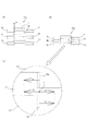
前記コアプレート片(3)は、一方の面に形成されると共に円周方向(C)の端部が円弧形状に形成された凸部(11)と、他方の面に形成され、前記コアプレート(2)が積層された際に他の層のコアプレート片(3)の凸部(11)と嵌合すると共に円周方向(C)の端部が円弧形状に形成された凹部(12)と、を有し、
前記凸部(11)の前記コアプレート(2)の半径方向(R)の幅(Wr2)を、前記凹部(12)の前記コアプレート(2)の半径方向(R)の幅(Wr1)よりも大きくし、これら凸部(11)及び凹部(12)の半径方向(R)の嵌め合いを締り嵌めにすると共に、
前記凸部(11)の前記コアプレート(2)の円周方向(C)の幅(Wc2)を、前記凹部(12)の前記コアプレート(2)の円周方向(C)の幅(Wc1)よりも小さくし、これら凸部(11)及び凹部(12)の円周方向の嵌め合いを隙間嵌めとした、
ことを特徴とする。
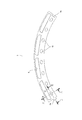
図1及び図2に示すように、IPMモータ(回転電機)用のロータコア1は、円環状のコアプレート2が複数積層されて形成されている。該コアプレート2は、電磁鋼板の母材から打ち抜かれた板状の部材であり、歩留まりの向上を図るために、均等に分割(本実施形態では5分割)された円弧状のコアプレート片3を連結して形成されている。
ついで、本発明の第2の実施形態について説明する。なお、第2の実施形態は、第1の実施形態に対してかしめ部の形状を変更したものであり、共通する構成については説明を省略すると共に、同一作用効果の部材については、第1の実施形態と同一の名称を使用する。
ついで、本発明の第3の実施形態について説明する。この第3の実施形態は、第1の実施形態に対してかしめ部の形状が相違したものであり、共通する構成については説明を省略すると共に、同一作用効果の部材については、第1の実施形態と同一の名称を使用する。
2 コアプレート
3 コアプレート片
10b 隙間嵌めとなる部分(円弧部)
11 凸部
12 凹部
Wr1 凹部のコアプレート半径方向の幅
Wr2 凸部のコアプレート半径方向の幅
Wc1 凹部のコアプレート円周方向の幅
Wc2 凸部のコアプレート円周方向の幅
d2 隙間
D1,D2 継ぎ目
R 半径方向
C 円周方向
Claims (1)
- 円環状のコアプレートを複数積層して形成されると共に、前記コアプレートを均等に分割した円弧状のコアプレート片が連結されて前記コアプレートの一層が形成され、かつ前記コアプレート片の継ぎ目の円周方向の位置が、所定枚数の前記コアプレート毎に前記コアプレートの積層方向で異なるように構成された回転電機のロータコアにおいて、
前記コアプレート片は、一方の面に形成されると共に円周方向の端部が円弧形状に形成された凸部と、他方の面に形成され、前記コアプレートが積層された際に他の層のコアプレート片の凸部と嵌合すると共に円周方向の端部が円弧形状に形成された凹部と、を有し、
前記凸部の前記コアプレートの半径方向の幅を、前記凹部の前記コアプレートの半径方向の幅よりも大きくし、これら凸部及び凹部の半径方向の嵌め合いを締り嵌めにすると共に、
前記凸部の前記コアプレートの円周方向の幅を、前記凹部の前記コアプレートの円周方向の幅よりも小さくし、これら凸部及び凹部の円周方向の嵌め合いを隙間嵌めとした、
ことを特徴とする回転電機のロータコア。
Priority Applications (5)
| Application Number | Priority Date | Filing Date | Title |
|---|---|---|---|
| JP2010258353A JP5510285B2 (ja) | 2010-11-18 | 2010-11-18 | 回転電機のロータコア |
| CN201180042943.5A CN103081302B (zh) | 2010-11-18 | 2011-11-11 | 旋转电机的转子铁芯 |
| PCT/JP2011/076094 WO2012067043A1 (ja) | 2010-11-18 | 2011-11-11 | 回転電機のロータコア |
| DE112011102611T DE112011102611T5 (de) | 2010-11-18 | 2011-11-11 | Rotorkern für eine drehende Elektromaschine |
| US13/295,676 US8456056B2 (en) | 2010-11-18 | 2011-11-14 | Rotor core for rotating electric machine |
Applications Claiming Priority (1)
| Application Number | Priority Date | Filing Date | Title |
|---|---|---|---|
| JP2010258353A JP5510285B2 (ja) | 2010-11-18 | 2010-11-18 | 回転電機のロータコア |
Publications (3)
| Publication Number | Publication Date |
|---|---|
| JP2012110161A JP2012110161A (ja) | 2012-06-07 |
| JP2012110161A5 JP2012110161A5 (ja) | 2013-04-04 |
| JP5510285B2 true JP5510285B2 (ja) | 2014-06-04 |
Family
ID=46063699
Family Applications (1)
| Application Number | Title | Priority Date | Filing Date |
|---|---|---|---|
| JP2010258353A Active JP5510285B2 (ja) | 2010-11-18 | 2010-11-18 | 回転電機のロータコア |
Country Status (5)
| Country | Link |
|---|---|
| US (1) | US8456056B2 (ja) |
| JP (1) | JP5510285B2 (ja) |
| CN (1) | CN103081302B (ja) |
| DE (1) | DE112011102611T5 (ja) |
| WO (1) | WO2012067043A1 (ja) |
Families Citing this family (13)
| Publication number | Priority date | Publication date | Assignee | Title |
|---|---|---|---|---|
| JP5459110B2 (ja) * | 2010-06-30 | 2014-04-02 | 株式会社デンソー | 回転電機の固定子 |
| JP6050084B2 (ja) * | 2012-10-19 | 2016-12-21 | ミネベア株式会社 | スピンドルモータおよびハードディスク駆動装置 |
| DE102013201199A1 (de) * | 2013-01-25 | 2014-07-31 | Magna Powertrain Ag & Co. Kg | Elektrische Maschine und Verfahren zur Herstellung eines Elektroblechs |
| WO2014204469A1 (en) | 2013-06-20 | 2014-12-24 | Otis Elevator Company | Electric machine having rotor with slanted permanent magnets |
| AU2014317744A1 (en) * | 2013-09-05 | 2016-04-07 | Skykar Inc. | Synchronous electric machines |
| JP6401466B2 (ja) * | 2014-03-10 | 2018-10-10 | 株式会社三井ハイテック | 積層鉄心及びその製造方法 |
| DE102017201438A1 (de) | 2017-01-30 | 2018-08-02 | Thyssenkrupp Ag | Blechpaketscheibe mit einer Mehrzahl von Blechpaketscheibensegmenten sowie Rotor |
| DE102017010685A1 (de) * | 2017-11-16 | 2019-05-16 | Wieland-Werke Ag | Kurzschlussläufer und Verfahren zur Herstellung eines Kurzschlussläufers |
| CN113555983A (zh) * | 2020-04-24 | 2021-10-26 | 采埃孚汽车英国有限公司 | 马达转子 |
| EP3958443A1 (en) | 2020-08-20 | 2022-02-23 | ATOP S.p.A. | Stator, apparatus and method for preparing a pre-shaped insulator |
| US12285109B2 (en) * | 2023-02-22 | 2025-04-29 | Hsin-Hua Chen | Positioner of chair adjusting device |
| DE102023123444A1 (de) | 2023-08-31 | 2025-03-06 | Schaeffler Technologies AG & Co. KG | Rotor einer elektrischen Rotationsmaschine, Verfahren zur Herstellung des Rotors und elektrische Rotationsmaschine |
| DE102024104034A1 (de) | 2024-02-14 | 2025-08-14 | Schaeffler Technologies AG & Co. KG | Kreisringabschnittsförmiges, aus einem Elektroblech geformtes Rotorsegment, Blechpaketanordnung, segmentierter Rotor und elektrische Maschine |
Family Cites Families (13)
| Publication number | Priority date | Publication date | Assignee | Title |
|---|---|---|---|---|
| US5075150A (en) * | 1987-06-22 | 1991-12-24 | Linton And Hirst | Pack of laminations with projections and depressions in torsionally flexible contact |
| JPH0614481A (ja) * | 1992-06-25 | 1994-01-21 | Mitsubishi Electric Corp | 電機子鉄心 |
| US5894182A (en) * | 1997-08-19 | 1999-04-13 | General Electric Company | Motor with rotor and stator core paired interlocks |
| US5992003A (en) * | 1997-11-13 | 1999-11-30 | Oberg Industries, Inc. | Method for spacing laminations |
| JP3848804B2 (ja) * | 1999-10-26 | 2006-11-22 | 松下電器産業株式会社 | 積層固着品 |
| JP2002262496A (ja) | 2001-03-05 | 2002-09-13 | Hitachi Ltd | 回転電機のコア構造 |
| JP3987027B2 (ja) * | 2003-03-31 | 2007-10-03 | 三菱電機株式会社 | 回転電機の電機子 |
| JP4599088B2 (ja) | 2004-05-13 | 2010-12-15 | 東芝コンシューマエレクトロニクス・ホールディングス株式会社 | 回転電機の回転子及びその製造方法 |
| JP5019967B2 (ja) * | 2007-06-20 | 2012-09-05 | パナソニック株式会社 | モータ用の積層コアとこれを用いるモータ |
| JP5276303B2 (ja) * | 2007-11-09 | 2013-08-28 | 株式会社三井ハイテック | 回転電機の回転子積層鉄心の製造方法 |
| WO2009093380A1 (ja) * | 2008-01-22 | 2009-07-30 | Kabushiki Kaisha Yaskawa Denki | 積層巻きコア及びこれを備えた回転子、回転電機 |
| JP5347321B2 (ja) * | 2008-05-01 | 2013-11-20 | 日産自動車株式会社 | 積層鉄心の製造方法および製造装置、並びに積層鉄心 |
| JP5072989B2 (ja) | 2010-03-05 | 2012-11-14 | 東芝コンシューマエレクトロニクス・ホールディングス株式会社 | 回転電機の回転子鉄心及びその製造方法 |
-
2010
- 2010-11-18 JP JP2010258353A patent/JP5510285B2/ja active Active
-
2011
- 2011-11-11 WO PCT/JP2011/076094 patent/WO2012067043A1/ja not_active Ceased
- 2011-11-11 CN CN201180042943.5A patent/CN103081302B/zh not_active Expired - Fee Related
- 2011-11-11 DE DE112011102611T patent/DE112011102611T5/de not_active Withdrawn
- 2011-11-14 US US13/295,676 patent/US8456056B2/en not_active Expired - Fee Related
Also Published As
| Publication number | Publication date |
|---|---|
| WO2012067043A1 (ja) | 2012-05-24 |
| US20120126658A1 (en) | 2012-05-24 |
| CN103081302A (zh) | 2013-05-01 |
| US8456056B2 (en) | 2013-06-04 |
| JP2012110161A (ja) | 2012-06-07 |
| CN103081302B (zh) | 2015-04-08 |
| DE112011102611T5 (de) | 2013-05-08 |
Similar Documents
| Publication | Publication Date | Title |
|---|---|---|
| JP5510285B2 (ja) | 回転電機のロータコア | |
| JP5231082B2 (ja) | 回転電機の回転子 | |
| JP2010104160A (ja) | デュアルロータモータおよびその製造方法 | |
| JP2010220288A (ja) | コアブロック及び該コアブロックを用いたモータ用の磁極コア | |
| JP5326642B2 (ja) | 回転電機及び回転電機の製造方法 | |
| US20130106234A1 (en) | Rotor for permanent magnet type rotating electrical machine, permanent magnet type rotating electrical machine, and method for manufacturing rotor | |
| CN110089005A (zh) | 旋转电机的转子和旋转电机 | |
| WO2014208582A1 (ja) | 回転電機用同期ロータと回転電機用同期ロータの製造方法 | |
| JP2012135063A (ja) | 回転電機のステータコア | |
| WO2017195498A1 (ja) | 回転子および回転電機 | |
| JP2013046466A (ja) | 回転子 | |
| JP2012110163A (ja) | 回転電機のロータコア | |
| CN103797688B (zh) | 旋转电机的转子 | |
| JP2005117796A (ja) | 回転電機のロータ | |
| JP7188588B2 (ja) | ロータ、及び、ロータの製造方法 | |
| JP2014204495A (ja) | 回転電機およびその製造方法 | |
| JP2011254616A (ja) | 固定子積層鉄心 | |
| JP2012110162A (ja) | 回転電機のロータコア | |
| JP7799162B2 (ja) | 分割型固定子および回転電機 | |
| JP2013143872A (ja) | 回転電機のロータコア及びその製造方法 | |
| JP7224471B2 (ja) | 回転電機の回転子、回転電機、回転電機の回転子の製造方法、および回転電機の製造方法 | |
| JP2012110164A (ja) | 回転電機のロータコア | |
| JP2012249354A (ja) | 回転電機の回転子 | |
| EP3723241B1 (en) | Rotor core for rotating electric machine and method for manufacturing rotor core for rotating electric machine | |
| JP5835839B2 (ja) | ステータコア、モータ、及びステータコアの製造方法 |
Legal Events
| Date | Code | Title | Description |
|---|---|---|---|
| A521 | Written amendment |
Free format text: JAPANESE INTERMEDIATE CODE: A523 Effective date: 20130220 |
|
| A621 | Written request for application examination |
Free format text: JAPANESE INTERMEDIATE CODE: A621 Effective date: 20130220 |
|
| TRDD | Decision of grant or rejection written | ||
| A01 | Written decision to grant a patent or to grant a registration (utility model) |
Free format text: JAPANESE INTERMEDIATE CODE: A01 Effective date: 20140225 |
|
| A61 | First payment of annual fees (during grant procedure) |
Free format text: JAPANESE INTERMEDIATE CODE: A61 Effective date: 20140310 |
|
| R150 | Certificate of patent or registration of utility model |
Ref document number: 5510285 Country of ref document: JP Free format text: JAPANESE INTERMEDIATE CODE: R150 |