WO2012063536A1 - 可変動弁装置 - Google Patents
可変動弁装置 Download PDFInfo
- Publication number
- WO2012063536A1 WO2012063536A1 PCT/JP2011/069469 JP2011069469W WO2012063536A1 WO 2012063536 A1 WO2012063536 A1 WO 2012063536A1 JP 2011069469 W JP2011069469 W JP 2011069469W WO 2012063536 A1 WO2012063536 A1 WO 2012063536A1
- Authority
- WO
- WIPO (PCT)
- Prior art keywords
- drive
- cam shaft
- variable valve
- rotation
- raceway surface
- Prior art date
Links
Images


Classifications
-
- F—MECHANICAL ENGINEERING; LIGHTING; HEATING; WEAPONS; BLASTING
- F01—MACHINES OR ENGINES IN GENERAL; ENGINE PLANTS IN GENERAL; STEAM ENGINES
- F01L—CYCLICALLY OPERATING VALVES FOR MACHINES OR ENGINES
- F01L1/00—Valve-gear or valve arrangements, e.g. lift-valve gear
- F01L1/34—Valve-gear or valve arrangements, e.g. lift-valve gear characterised by the provision of means for changing the timing of the valves without changing the duration of opening and without affecting the magnitude of the valve lift
- F01L1/344—Valve-gear or valve arrangements, e.g. lift-valve gear characterised by the provision of means for changing the timing of the valves without changing the duration of opening and without affecting the magnitude of the valve lift changing the angular relationship between crankshaft and camshaft, e.g. using helicoidal gear
- F01L1/356—Valve-gear or valve arrangements, e.g. lift-valve gear characterised by the provision of means for changing the timing of the valves without changing the duration of opening and without affecting the magnitude of the valve lift changing the angular relationship between crankshaft and camshaft, e.g. using helicoidal gear making the angular relationship oscillate, e.g. non-homokinetic drive
-
- F—MECHANICAL ENGINEERING; LIGHTING; HEATING; WEAPONS; BLASTING
- F01—MACHINES OR ENGINES IN GENERAL; ENGINE PLANTS IN GENERAL; STEAM ENGINES
- F01L—CYCLICALLY OPERATING VALVES FOR MACHINES OR ENGINES
- F01L1/00—Valve-gear or valve arrangements, e.g. lift-valve gear
- F01L1/34—Valve-gear or valve arrangements, e.g. lift-valve gear characterised by the provision of means for changing the timing of the valves without changing the duration of opening and without affecting the magnitude of the valve lift
-
- F—MECHANICAL ENGINEERING; LIGHTING; HEATING; WEAPONS; BLASTING
- F01—MACHINES OR ENGINES IN GENERAL; ENGINE PLANTS IN GENERAL; STEAM ENGINES
- F01L—CYCLICALLY OPERATING VALVES FOR MACHINES OR ENGINES
- F01L13/00—Modifications of valve-gear to facilitate reversing, braking, starting, changing compression ratio, or other specific operations
- F01L13/0015—Modifications of valve-gear to facilitate reversing, braking, starting, changing compression ratio, or other specific operations for optimising engine performances by modifying valve lift according to various working parameters, e.g. rotational speed, load, torque
- F01L13/0021—Modifications of valve-gear to facilitate reversing, braking, starting, changing compression ratio, or other specific operations for optimising engine performances by modifying valve lift according to various working parameters, e.g. rotational speed, load, torque by modification of rocker arm ratio
- F01L13/0026—Modifications of valve-gear to facilitate reversing, braking, starting, changing compression ratio, or other specific operations for optimising engine performances by modifying valve lift according to various working parameters, e.g. rotational speed, load, torque by modification of rocker arm ratio by means of an eccentric
-
- F—MECHANICAL ENGINEERING; LIGHTING; HEATING; WEAPONS; BLASTING
- F02—COMBUSTION ENGINES; HOT-GAS OR COMBUSTION-PRODUCT ENGINE PLANTS
- F02D—CONTROLLING COMBUSTION ENGINES
- F02D13/00—Controlling the engine output power by varying inlet or exhaust valve operating characteristics, e.g. timing
- F02D13/02—Controlling the engine output power by varying inlet or exhaust valve operating characteristics, e.g. timing during engine operation
- F02D13/0203—Variable control of intake and exhaust valves
- F02D13/0215—Variable control of intake and exhaust valves changing the valve timing only
-
- F—MECHANICAL ENGINEERING; LIGHTING; HEATING; WEAPONS; BLASTING
- F01—MACHINES OR ENGINES IN GENERAL; ENGINE PLANTS IN GENERAL; STEAM ENGINES
- F01L—CYCLICALLY OPERATING VALVES FOR MACHINES OR ENGINES
- F01L1/00—Valve-gear or valve arrangements, e.g. lift-valve gear
- F01L1/02—Valve drive
- F01L1/04—Valve drive by means of cams, camshafts, cam discs, eccentrics or the like
- F01L1/047—Camshafts
- F01L2001/0471—Assembled camshafts
- F01L2001/0473—Composite camshafts, e.g. with cams or cam sleeve being able to move relative to the inner camshaft or a cam adjusting rod
-
- F—MECHANICAL ENGINEERING; LIGHTING; HEATING; WEAPONS; BLASTING
- F01—MACHINES OR ENGINES IN GENERAL; ENGINE PLANTS IN GENERAL; STEAM ENGINES
- F01L—CYCLICALLY OPERATING VALVES FOR MACHINES OR ENGINES
- F01L1/00—Valve-gear or valve arrangements, e.g. lift-valve gear
- F01L1/02—Valve drive
- F01L1/04—Valve drive by means of cams, camshafts, cam discs, eccentrics or the like
- F01L1/047—Camshafts
- F01L1/053—Camshafts overhead type
- F01L2001/0537—Double overhead camshafts [DOHC]
-
- F—MECHANICAL ENGINEERING; LIGHTING; HEATING; WEAPONS; BLASTING
- F02—COMBUSTION ENGINES; HOT-GAS OR COMBUSTION-PRODUCT ENGINE PLANTS
- F02B—INTERNAL-COMBUSTION PISTON ENGINES; COMBUSTION ENGINES IN GENERAL
- F02B75/00—Other engines
- F02B75/12—Other methods of operation
- F02B2075/125—Direct injection in the combustion chamber for spark ignition engines, i.e. not in pre-combustion chamber
-
- Y—GENERAL TAGGING OF NEW TECHNOLOGICAL DEVELOPMENTS; GENERAL TAGGING OF CROSS-SECTIONAL TECHNOLOGIES SPANNING OVER SEVERAL SECTIONS OF THE IPC; TECHNICAL SUBJECTS COVERED BY FORMER USPC CROSS-REFERENCE ART COLLECTIONS [XRACs] AND DIGESTS
- Y02—TECHNOLOGIES OR APPLICATIONS FOR MITIGATION OR ADAPTATION AGAINST CLIMATE CHANGE
- Y02T—CLIMATE CHANGE MITIGATION TECHNOLOGIES RELATED TO TRANSPORTATION
- Y02T10/00—Road transport of goods or passengers
- Y02T10/10—Internal combustion engine [ICE] based vehicles
- Y02T10/12—Improving ICE efficiencies
Definitions
- Patent Literature 1 discloses a valve operating apparatus for an internal combustion engine having a configuration in which a drive cam shaft to which a driven cam lobe for driving a valve is fixed is driven to rotate by an electric motor.
- the conventional valve gear includes a motor control device that controls the rotation speed of the electric motor. According to such a configuration, by changing the rotation speed of the electric motor by the motor control device, the rotation speed of the driven cam lobe during one rotation of the drive cam shaft can be increased or decreased.
- the applicant has recognized the following documents including the above-mentioned documents as related to the present invention.
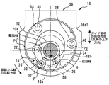
- the guide member 36 includes an annular portion 36a having the raceway surface 36a1 for each cylinder.
- the annular portion 36a of each cylinder is integrally connected by being bridged via a bridging portion 36b.
- the guide member 36 is movable in the vertical direction in FIG. 3 (that is, the vertical direction of the cylinder), and is restricted from moving in the horizontal direction in FIG. 3 and the axial direction of the drive cam shaft 12. In the aspect, it is supported by a cylinder head or a cam carrier (that is, a cam housing) (not shown) via a predetermined support member (not shown). Further, it is assumed that the guide member 36 is biased toward a working angle variable cam 52 described later by a return spring (not shown).
- the raceway surface 36a1 has moved most in the moving range in the downward direction (downward direction of the cylinder) in FIG. 6 compared with the reference state shown in FIG. 6B. Indicates the state. In this state, the distance between the rotation center of the drive camshaft 12 and the rotation center of the control roller 32 (the control rotation fulcrum) of the section on the substantially lower half side of the track surface 36a1 is wider than that in the reference state. It becomes a vast section. As shown in FIG. 7 (B), the contact point P of the control roller 32 when passing through this wide section moves from the right rotation angle point P0 on the right side in FIG. 6 (C) to a position directly below the track surface 36a1.
- control roller 32 is employed as a contact member that comes into contact with the raceway surface 36a1, and rolls on the raceway surface 36a1. For this reason, as compared with the case where a member that makes contact with the raceway surface 36a1 by using sliding is adopted as the contact member, friction and wear of the contact portion can be reduced.
- FIG. 12 is a schematic diagram for explaining the operation of the variable valve apparatus 60 when the eccentric angle ⁇ is changed by 90 °.
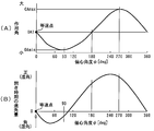
- FIG. 13 is a diagram showing a change tendency of the valve opening characteristic of the intake valve 70 in accordance with the change of the eccentric angle ⁇ in the variable valve apparatus 60. More specifically, FIG. 13A shows the tendency of the change in the operating angle of the intake valve 70 accompanying the change in the eccentric angle ⁇ , and FIG. 13B shows the change in the eccentric angle ⁇ . It is the figure showing the tendency of the change of the opening time of the accompanying intake valve 70.
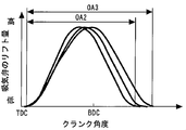
- FIG. FIG. 14 is a diagram showing each lift curve of the intake valve 70 obtained when the eccentric angle ⁇ is changed by 90 °. Each figure in FIG.
- the operation state shown in FIG. 12A is a state where the eccentric angle ⁇ is 0 °, that is, a state where the rotation center of the drive cam shaft 12 and the center of the track surface 64a coincide.
- the driven cam lobe 18a rotates once with the drive cam shaft 12 at a constant speed.
- the operating angle of the intake valve 70 obtained in this case is hereinafter referred to as “OA1” as shown in FIG. 13 for convenience of explanation.
- the speed-up action in the first half of the lift section of the intake valve 70 and the speed-down action in the second half are offset, and as a result
- the operating angle of the intake valve 70 is the same value OA1 as that at the constant speed, as shown in FIG.
- the variable valve device 60 of the present embodiment is a device of a system that rotationally drives a control sleeve 64 (guide member) having a raceway surface 64a in order to change the working angle. Accordingly, even when the control sleeve 64 is rotationally driven in a direction against the above-described component force in the circumferential direction, the load torque of the actuator 62 when the control sleeve 64 is rotationally driven to vary the operating angle is It becomes a small torque based on the component of the direction.
Landscapes
- Engineering & Computer Science (AREA)
- Mechanical Engineering (AREA)
- General Engineering & Computer Science (AREA)
- Chemical & Material Sciences (AREA)
- Combustion & Propulsion (AREA)
- Valve Device For Special Equipments (AREA)
- Valve-Gear Or Valve Arrangements (AREA)
- Output Control And Ontrol Of Special Type Engine (AREA)
Abstract
Description
尚、出願人は、本発明に関連するものとして、上記の文献を含めて、以下に記載する文献を認識している。
駆動カム軸は、クランク軸の回転力によって回転駆動される。従動カムロブは、前記駆動カム軸と同心であって、当該駆動カム軸に回転自在に支持されている。ガイド部材は、前記駆動カム軸を覆うように形成された軌道面を有する。リンク機構は、前記駆動カム軸および前記従動カムロブのそれぞれに連結され、前記軌道面と接触する接触部材を有し、前記駆動カム軸の回転中心に対する前記接触部材の位置変化に伴って前記駆動カム軸に対する前記従動カムロブの回転角度を変化させる。接触維持手段は、前記駆動カム軸が一回転する間、当該駆動カム軸の周りを回る前記接触部材と前記軌道面との接触が維持されるようにする。アクチュエータは、前記軌道面を、前記駆動カム軸の軸線と直交する平面方向に移動させる。
これにより、ガイド部材自体を上記平面方向に移動させる構成を有するアクチュエータを用いて、駆動カム軸が一回転する間の従動カムロブの回転速度を変更可能とする可変動弁装置を実現することができる。
これにより、駆動カム軸が一回転する間に、駆動カム軸に対する従動カムロブの回転角度を変化させることができる。
これにより、アクチュエータによるガイド部材の軌道面の位置調整に応じた接触部材の位置変化に応じて、カム軸側リンク部材およびカムロブ側リンク部材を介して、駆動カム軸に対する従動カムロブの回転角度を変化させることができる。このため、ガイド部材の軌道面の制御位置に応じて、駆動カム軸が一回転する間の従動カムロブの回転速度を変更することができる。
これにより、アクチュエータによるガイド部材の軌道面の位置調整に応じた接触部材の位置変化に応じて、パンタグラフ状に連結されたリンク機構が動作し、駆動カム軸に対する従動カムロブの回転角度を変化させることができる。
これにより、接触部材およびカムロブ側リンク部材がカム軸側リンク部材に対して駆動カム軸の回転方向前方側に配置されているため、上記狭小区間と重なる従動カムロブのリフト区間が到来した場合に、駆動カム軸に対して前方に進みながら従動カムロブが回転することになる。このため、上記狭小区間と重なる従動カムロブのリフト区間が到来した場合に、軌道面の中心点が駆動カム軸の回転中心を通る状態の時と比べ、バルブのリフト動作を早めることができる。
これにより、接触部材およびカムロブ側リンク部材がカム軸側リンク部材に対して駆動カム軸の回転方向後方側に配置されているため、上記狭小区間と重なる従動カムロブのリフト区間が到来した場合に、駆動カム軸に対して遅れながら従動カムロブが回転することになる。このため、上記狭小区間と重なる従動カムロブのリフト区間が到来した場合に、軌道面の中心点が駆動カム軸の回転中心を通る状態の時と比べ、バルブのリフト動作を遅くすることができる。
これにより、内燃機関(シリンダヘッド)の上方へのガイド部材の移動量を相対的に小さくすることで、内燃機関の上方の歩行者保護用等のスペースを良好に確保できるようになる。
これにより、例えばバネを利用して軌道面と接触部材との接触が維持されるようにする場合と比べ、フリクションや摩耗を低減することができる。
これにより、軌道面と支持部材との間に、少なくとも2つの保持ローラーおよび制御ローラーが介在しているので、例えば支持部材と軌道面とを直接的に摺動させる場合と比べ、接触部のフリクションや摩耗を低減することができる。
これにより、ガイド部材を回転駆動することによってガイド部材の回転中心に対して偏心した中心を有する軌道面を上記平面方向に移動させる構成を有するアクチュエータを用いて、駆動カム軸が一回転する間の従動カムロブの回転速度を変更可能とする可変動弁装置を実現することができる。
これにより、アクチュエータによるガイド部材の軌道面の位置調整に応じた接触部材の位置変化に応じて、カム軸側リンク部材およびカムロブ側リンク部材を介して、駆動カム軸に対する従動カムロブの回転角度を変化させることができる。このため、ガイド部材の軌道面の制御位置に応じて、駆動カム軸が一回転する間の従動カムロブの回転速度を変更することができる。
これにより、アクチュエータによるガイド部材の軌道面の位置調整に応じた接触部材の位置変化に応じて、パンタグラフ状に連結されたリンク機構が動作し、駆動カム軸に対する従動カムロブの回転角度を変化させることができる。
このように、アクチュエータによって駆動カム軸の回転に伴って軌道面に沿って移動する接触部材の公転中心を移動させることにより、駆動カム軸が一回転する間に、駆動カム軸に対する従動カムロブの回転角度を変化させることができる。
これにより、円周面である軌道面の中心が駆動カム軸の回転中心と一致するようにガイド部材を回転させることにより、駆動カム軸が一回転する間の従動カムロブが等速となる動作状態を得ることができるようになる。
これにより、例えばバネを利用して軌道面と接触部材との接触が維持されるようにする場合と比べ、フリクションや摩耗を低減することができる。
これにより、軌道面と支持部材との間に、少なくとも2つの保持ローラーおよび制御ローラーが介在しているので、例えば支持部材と軌道面とを直接的に摺動させる場合と比べ、接触部のフリクションや摩耗を低減することができる。
[実施の形態1における可変動弁装置の構成]
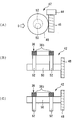
図1は、本発明の実施の形態1の可変動弁装置10の全体構成を概略的に示す斜視図である。図2は、図1に示す可変動弁装置10が備える駆動カム軸12周りの構成を説明するための図である。
図3は、可変動弁装置10を、図1に示すA-A線で切断した断面図である。図4は、図1における矢視B方向から可変動弁装置10を見た斜視図である。尚、図3においては、リンクプレート34の一部の図示を省略しており、図4においては、ガイド部材36の図示を省略している。
上記回転角度θは、ここでは、図3に示すように、駆動カム軸12の軸方向から見て、駆動カム軸12の中心点とカム軸側回転支点とを結ぶ直線(駆動軸)と、駆動カム軸12の中心点とカムロブ側回転支点とを結ぶ直線(従動軸)とのなす角度として定義されている。
また、図3に示す状態は、アクチュエータ42によって軌道面36a1が図3の上方向に移動させられたことによって、軌道面36a1の中心点が駆動カム軸12の中心点よりも図3の上方向に変位した状態を示している。この状態では、制御ローラー32が軌道面36a1のほぼ下半分側に位置している時に、駆動カム軸12の回転中心と制御ローラー32の回転中心(上記制御回転支点)との距離が上記基準状態の時よりも狭められることになる。以下の明細書中においては、上記基準状態時よりも上記距離が狭められている軌道面36a1の区間(図3の場合にはほぼ下半分側の区間)のことを、単に「狭小区間」と称することとする。
次に、図6および図7を参照して、本実施形態の可変動弁装置10の動作について説明する。
図6は、ガイド部材36の変位に伴う可変動弁装置10の動作を説明するための模式図である。尚、図6の各図は、上記図3とは逆方向から可変動弁装置10の主たる構成を模式的に表した図である。また、図7は、ガイド部材36の変位に伴う、バルブの作用角の変化、および上記基準状態時の値θ0に対する駆動カム軸12と従動カムロブ18aとの回転角度θの差(変化)を表した図である。
このように、本実施形態の可変動弁装置10によれば、クランク軸の回転力によって駆動カム軸12を駆動する構成を用いる場合において、装置構成を極力複雑にすることなく、駆動カム軸12が一回転する間の従動カムロブ18aの回転速度を変更可能とすることができる。
また、上述した実施の形態1においては、駆動リンク24が本発明における「カム軸側リンク部材」に、従動リンク28が本発明における「カムロブ側リンク部材」に、それぞれ相当している。
また、上述した実施の形態1においては、リンクプレート34が本発明における「支持部材」に相当している。
次に、図9乃至図18を参照して、本発明の実施の形態2について説明する。
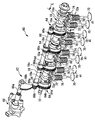
図9は、本発明の実施の形態2における可変動弁装置60の全体構成を概略的に示す斜視図である。図10は、可変動弁装置60を、図9に示すE-E線で切断した断面図である。尚、図9および図10において、上述した実施の形態1の可変動弁装置10の構成要素と同一の要素については、同一の符号を付してその説明を省略または簡略する。
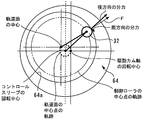
以下、本明細書中においては、駆動カム軸12の回転中心と軌道面64aの中心との偏心量を特定するための指標として、「偏心角度φ」を用いることとする。ここでは、図10に示すように、偏心角度φは、駆動カム軸12の軸方向から見て、コントロールスリーブ64の回転中心から駆動カム軸12の回転中心に向かう直線と、コントロールスリーブ64の回転中心から軌道面64aの中心点に向かう直線とのなす角度として定義されている。より具体的には、軌道面64aの中心点と駆動カム軸12の中心点とが一致している状態では、偏心角度φは0°となる。そして、偏心角度φは、図10中の反時計回りにおけるコントロールスリーブ64の回転量が大きくなることによって軌道面64aの中心点がその軌跡上を反時計回りに大きく回転するほど、大きな値となるように定義されている。また、図10に示す状態(すなわち、軌道面64aの中心点がコントロールスリーブ64の回転中心を通る鉛直線を基準として駆動カム軸12の回転中心と線対称な位置にある状態)では、偏心角度φは180°となる。駆動カム軸12の回転中心と軌道面64aの中心点との偏心量は、偏心角度φが180°である時に最大となる。
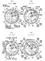
次に、図11乃至図16を参照して、本実施形態の可変動弁装置60の動作、更にはその効果について説明する。
図11に示す偏心状態では、制御ローラー32の接点Pが軌道面64aのほぼ右半分側の狭小区間中の点P1に位置している時に、駆動カム軸12の回転中心と制御ローラー32の回転中心(制御回転支点)との距離が最も小さくなり、駆動軸と従動軸との間の回転角度θが最も拡大する。一方、この偏心状態では、制御ローラー32の接点Pが軌道面64aのほぼ左半分側の広大区間中の点P2に位置している時に、駆動カム軸12の回転中心と制御ローラー32の回転中心(制御回転支点)との距離が最も大きくなり、駆動軸と従動軸との間の回転角度θが最も縮小する。つまり、制御ローラー32の接点Pが点P2から点P1に向かって移動する間は、単位カム角当たりの回転角度θの変化量が増加するため、従動カムロブ18aの回転速度が駆動カム軸12の回転速度よりも高くなり(増速し)、一方、制御ローラー32の接点Pが点P1から点P2に向かって移動する間は、単位カム角当たりの回転角度θの変化量が減少するため、従動カムロブ18aの回転速度が駆動カム軸12の回転速度よりも低くなる(減速する)。このため、以下の明細書中においては、軌道面64a上における点P2から点P1までの区間を、単に「増速区間」と称し、軌道面64a上における点P1から点P2までの区間を、単に「減速区間」と称することとする。
このように、本実施形態の可変動弁装置60によっても、クランク軸の回転力によって駆動カム軸12を駆動する構成を用いる場合において、装置構成を極力複雑にすることなく、駆動カム軸12が一回転する間の従動カムロブ18aの回転速度を変更可能とすることができる。
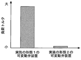
図15は、駆動カム軸12の回転に伴うリンク機構35の回転時に、制御ローラー32から軌道面64aに作用する力を表した図である。図16は、実施の形態1の可変動弁装置10と本実施形態の可変動弁装置60との間で、作用角可変時の負荷トルクの大きさを比較して表した図である。
図17(B)に示す開弁特性が得られる可変動弁装置によれば、上記大作用角範囲内において偏心角度φを連続的に変更することにより、図18に示すように、吸気弁の開き時期を一定としつつ、作用角をOA2からOA3の間で連続的に変更すること(すなわち、位相連成)が可能となる。尚、実施の形態2において上述した基本構成を有する本可変動弁装置によれば、各調整要素の設定次第で、図17(B)に示すような大作用角範囲以外の任意の作用角範囲において位相連成を可能にすることもできる。
また、上述した実施の形態2においては、駆動リンク24が本発明における「カム軸側リンク部材」に、従動リンク28が本発明における「カムロブ側リンク部材」に、それぞれ相当している。
また、上述した実施の形態2においては、リンクプレート34が本発明における「支持部材」に相当している。
12 駆動カム軸
14 タイミングプーリー
16 可変バルブタイミング(VVT)機構
18 カムピース
18a 従動カムロブ
18a1 従動カムロブのベース円部
18a2 従動カムロブのノーズ部
18b 従動カムロブの従動アーム部
20 駆動アーム
20a 駆動アームの駆動アーム部
22 カム軸側回転軸
24 駆動リンク
26 カムロブ側回転軸
28 従動リンク
30 制御ローラー側回転軸
32 制御ローラー
34 リンクプレート
35 リンク機構
36 ガイド部材
36a ガイド部材の環状部
36a1 ガイド部材の軌道面
36b ガイド部材の架橋部
38 保持ローラー
40 保持用回転軸
42、62 アクチュエータ
44、68 電動モータ
46 ウォームギヤ
48 ウォームホイール
50、66 制御軸
52 作用角可変カム
64 コントロールスリーブ
64a コントロールスリーブの軌道面
64bコントロールスリーブのギヤ
66a、66b 制御軸のギヤ
68a 電動モータの出力軸
68b 電動モータ側のギヤ
70 バルブ(例えば、吸気弁)
72 ロッカーアーム
72a ロッカーローラー
74 油圧式ラッシュアジャスタ
76 バルブスプリング
Claims (17)
- クランク軸の回転力によって回転駆動される駆動カム軸と、
前記駆動カム軸と同心であって、当該駆動カム軸に回転自在に支持された従動カムロブと、
前記駆動カム軸を覆うように形成された軌道面を有するガイド部材と、
前記駆動カム軸および前記従動カムロブのそれぞれに連結され、前記軌道面と接触する接触部材を有し、前記駆動カム軸の回転中心に対する前記接触部材の位置変化に伴って前記駆動カム軸に対する前記従動カムロブの回転角度を変化させるリンク機構と、
前記駆動カム軸が一回転する間、当該駆動カム軸の周りを回る前記接触部材と前記軌道面との接触が維持されるようにする接触維持手段と、
前記軌道面を、前記駆動カム軸の軸線と直交する平面方向に移動させるアクチュエータと、
を備えることを特徴とする可変動弁装置。 - 前記アクチュエータは、前記ガイド部材自体を前記平面方向に移動させることにより、前記軌道面を前記平面方向に移動させるものであることを特徴とする請求項1記載の可変動弁装置。
- 前記アクチュエータは、前記駆動カム軸の回転に伴って前記軌道面に沿って移動する前記接触部材の公転中心を移動させるものであることを特徴とする請求項2記載の可変動弁装置。
- 前記リンク機構は、
前記駆動カム軸の回転中心から径方向に離れた位置において当該駆動カム軸に設けられたカム軸側回転支点を中心として当該駆動カム軸に回転自在に連結されたカム軸側リンク部材と、
前記駆動カム軸の回転中心から径方向に離れた位置において前記従動カムロブに設けられたカムロブ側回転支点を中心として当該従動カムロブに回転自在に連結されたカムロブ側リンク部材と、
を含み、
前記接触部材は、前記カム軸側リンク部材の他端と前記カムロブ側リンク部材の他端とを制御回転支点において回転自在に連結する部材であることを特徴とする請求項2または3記載の可変動弁装置。 - 前記リンク機構では、前記制御回転支点において回転自在に連結された前記カム軸側リンク部材および前記カムロブ側リンク部材が、前記カム軸側回転支点および前記カムロブ側回転支点を介して、回転中心を共通とする前記駆動カム軸および前記従動カムロブに対してパンタグラフ状に連結されていることを特徴とする請求項4記載の可変動弁装置。
- 前記軌道面は、円周面であって、
前記カムロブ側リンク部材は、前記カム軸側リンク部材との間に前記接触部材を介在させた状態で当該カム軸側リンク部材に対して前記駆動カム軸の回転方向前方側に配置されており、
前記アクチュエータは、前記駆動カム軸の軸方向から見て、前記軌道面の中心点が前記駆動カム軸の軸線の法線方向かつ前記内燃機関の気筒の軸線方向に沿って移動するように前記ガイド部材を移動させるものであって、
前記軌道面の前記中心点が前記駆動カム軸の回転中心を通る状態に対して前記アクチュエータによって前記ガイド部材を気筒の上方向に移動させた状態で、前記従動カムロブのリフト区間中に前記接触部材が、前記駆動カム軸の当該回転中心と前記制御回転支点との距離が狭められることになる前記軌道面の狭小区間を通過するように設定されていることを特徴とする請求項4または5記載の可変動弁装置。 - 前記軌道面は、円周面であって、
前記カムロブ側リンク部材は、前記カム軸側リンク部材との間に前記接触部材を介在させた状態で当該カム軸側リンク部材に対して前記駆動カム軸の回転方向後方側に配置されており、
前記アクチュエータは、前記駆動カム軸の軸方向から見て、前記軌道面の中心点が前記駆動カム軸の軸線の法線方向かつ前記内燃機関の気筒の軸線方向に沿って移動するように前記ガイド部材を移動させるものであって、
前記軌道面の前記中心点が前記駆動カム軸の回転中心を通る状態に対して前記アクチュエータによって前記ガイド部材を気筒の上方向に移動させた状態で、前記従動カムロブのリフト区間中に前記接触部材が、前記駆動カム軸の当該回転中心と前記制御回転支点との距離が狭められることになる前記軌道面の狭小区間を通過するように設定されていることを特徴とする請求項4または5記載の可変動弁装置。 - 前記可変動弁装置は、シリンダヘッドがボンネットフードに対向するように車両に搭載された内燃機関に備えられたものであって、
前記軌道面は、円周面であって、
前記アクチュエータは、前記駆動カム軸の軸方向から見て、前記軌道面の中心点が前記駆動カム軸の軸線の法線方向かつ前記内燃機関の気筒の軸線方向に沿って移動するように前記ガイド部材を移動させるものであって、
前記軌道面の前記中心点が前記駆動カム軸の回転中心を通る状態を基準として、前記アクチュエータによる前記ガイド部材の前記気筒の上方向への移動量が、当該気筒の下方向への移動量に比して小さくなるように設定されていることを特徴とする請求項2乃至7の何れか1項記載の可変動弁装置。 - 前記接触維持手段は、前記軌道面によって前記駆動カム軸の径方向の位置が規定される部材であって、前記接触部材を支持する支持部材であることを特徴とする請求項2乃至8の何れか1項記載の可変動弁装置。
- 前記接触部材は、前記軌道面上を転動する制御ローラーを含み、
前記接触維持手段は、前記支持部材に回転自在に取り付けられた少なくとも2つの保持ローラーを含み、
前記支持部材は、当該少なくとも2つの保持ローラーと前記制御ローラーを介して、前記軌道面によって前記駆動カム軸の径方向の位置が規定されることを特徴とする請求項9記載の可変動弁装置。 - 前記アクチュエータは、前記ガイド部材を回転駆動するものであり、
前記軌道面は、円周面であって、
前記軌道面は、前記ガイド部材の回転中心に対して前記軌道面の中心が偏心した状態で、前記ガイド部材に備えられていることを特徴とする請求項1記載の可変動弁装置。 - 前記リンク機構は、
前記駆動カム軸の回転中心から径方向に離れた位置において当該駆動カム軸に設けられたカム軸側回転支点を中心として当該駆動カム軸に回転自在に連結されたカム軸側リンク部材と、
前記駆動カム軸の回転中心から径方向に離れた位置において前記従動カムロブに設けられたカムロブ側回転支点を中心として当該従動カムロブに回転自在に連結されたカムロブ側リンク部材と、
を含み、
前記接触部材は、前記カム軸側リンク部材の他端と前記カムロブ側リンク部材の他端とを制御回転支点において回転自在に連結する部材であることを特徴とする請求項11記載の可変動弁装置。 - 前記リンク機構では、前記制御回転支点において回転自在に連結された前記カム軸側リンク部材および前記カムロブ側リンク部材が、前記カム軸側回転支点および前記カムロブ側回転支点を介して、回転中心を共通とする前記駆動カム軸および前記従動カムロブに対してパンタグラフ状に連結されていることを特徴とする請求項12記載の可変動弁装置。
- 前記アクチュエータは、前記駆動カム軸の回転に伴って前記軌道面に沿って移動する前記接触部材の公転中心を移動させるものであることを特徴とする請求項11乃至13の何れか1項記載の可変動弁装置。
- 前記駆動カム軸の軸方向から見て、前記アクチュエータによって前記ガイド部材が回転駆動される際の前記軌道面の中心点の軌跡上に、前記駆動カム軸の前記回転中心が位置するように、前記ガイド部材と前記駆動カム軸との位置関係が設定されていることを特徴とする請求項11乃至14の何れか1項記載の可変動弁装置。
- 前記接触維持手段は、前記軌道面によって前記駆動カム軸の径方向の位置が規定される部材であって、前記接触部材を支持する支持部材であることを特徴とする請求項11乃至15の何れか1項記載の可変動弁装置。
- 前記接触部材は、前記軌道面上を転動する制御ローラーを含み、
前記接触維持手段は、当該支持部材に回転自在に取り付けられた少なくとも2つの保持ローラーを含み、
前記支持部材は、前記少なくとも2つの保持ローラーと前記制御ローラーを介して、前記軌道面によって前記駆動カム軸の径方向の位置が規定されることを特徴とする請求項16記載の可変動弁装置。
Priority Applications (4)
| Application Number | Priority Date | Filing Date | Title |
|---|---|---|---|
| US13/877,249 US8955478B2 (en) | 2010-11-08 | 2011-08-29 | Variable valve operating apparatus |
| EP11840014.2A EP2639416B1 (en) | 2010-11-08 | 2011-08-29 | Variable valve device |
| JP2012542833A JP5582195B2 (ja) | 2010-11-08 | 2011-08-29 | 可変動弁装置 |
| CN201180053667.2A CN103201465B (zh) | 2010-11-08 | 2011-08-29 | 可变气门装置 |
Applications Claiming Priority (2)
| Application Number | Priority Date | Filing Date | Title |
|---|---|---|---|
| JP2010-250033 | 2010-11-08 | ||
| JP2010250033 | 2010-11-08 |
Publications (1)
| Publication Number | Publication Date |
|---|---|
| WO2012063536A1 true WO2012063536A1 (ja) | 2012-05-18 |
Family
ID=46050693
Family Applications (2)
| Application Number | Title | Priority Date | Filing Date |
|---|---|---|---|
| PCT/JP2011/069470 WO2012063537A1 (ja) | 2010-11-08 | 2011-08-29 | 内燃機関の可変動弁装置 |
| PCT/JP2011/069469 WO2012063536A1 (ja) | 2010-11-08 | 2011-08-29 | 可変動弁装置 |
Family Applications Before (1)
| Application Number | Title | Priority Date | Filing Date |
|---|---|---|---|
| PCT/JP2011/069470 WO2012063537A1 (ja) | 2010-11-08 | 2011-08-29 | 内燃機関の可変動弁装置 |
Country Status (5)
| Country | Link |
|---|---|
| US (2) | US9046012B2 (ja) |
| EP (2) | EP2639416B1 (ja) |
| JP (2) | JP5582196B2 (ja) |
| CN (2) | CN103201465B (ja) |
| WO (2) | WO2012063537A1 (ja) |
Cited By (2)
| Publication number | Priority date | Publication date | Assignee | Title |
|---|---|---|---|---|
| CN104870761A (zh) * | 2012-12-25 | 2015-08-26 | 丰田自动车株式会社 | 可变气门装置 |
| WO2019039217A1 (ja) * | 2017-08-24 | 2019-02-28 | マツダ株式会社 | 車両用パワートレインユニット |
Families Citing this family (49)
| Publication number | Priority date | Publication date | Assignee | Title |
|---|---|---|---|---|
| JP5582196B2 (ja) | 2010-11-08 | 2014-09-03 | トヨタ自動車株式会社 | 内燃機関の可変動弁装置 |
| DE102013018263A1 (de) * | 2013-10-30 | 2015-04-30 | Avl Deutschland Gmbh | Verfahren und Anordnung zur Überwachung einer Aktuatorvorrichtung |
| KR101619389B1 (ko) * | 2014-12-10 | 2016-05-18 | 현대자동차 주식회사 | 연속 가변 밸브 듀레이션 장치 및 이를 포함하는 엔진 |
| KR20160070622A (ko) | 2014-12-10 | 2016-06-20 | 현대자동차주식회사 | 연속 가변 밸브 듀레이션 장치 및 이를 이용한 제어방법 |
| KR101655170B1 (ko) * | 2015-06-19 | 2016-09-07 | 현대자동차 주식회사 | 연속 가변 밸브 듀레이션 시스템 및 이를 포함하는 엔진 |
| KR101646135B1 (ko) * | 2015-06-22 | 2016-08-05 | 현대자동차 주식회사 | 연속 가변 밸브 리프트 장치 및 이를 포함하는 엔진 |
| US10480358B2 (en) | 2015-06-22 | 2019-11-19 | Hyundai Motor Company | Continuously variable valve timing apparatus and engine provided with the same |
| KR101628085B1 (ko) | 2015-06-22 | 2016-06-08 | 현대자동차 주식회사 | 연속 가변 밸브 듀레이션 장치 및 이를 포함하는 엔진 |
| KR101734261B1 (ko) | 2015-07-07 | 2017-05-24 | 현대자동차 주식회사 | 연속 가변 밸브 타이밍 장치 및 이를 포함하는 엔진 |
| KR101628088B1 (ko) | 2015-07-07 | 2016-06-08 | 현대자동차 주식회사 | 연속 가변 밸브 듀레이션 장치 및 이를 포함하는 엔진 |
| KR20170035712A (ko) * | 2015-09-23 | 2017-03-31 | 현대자동차주식회사 | 연속 가변 밸브 듀레이션 장치를 이용한 제어방법 |
| KR101664079B1 (ko) * | 2015-09-24 | 2016-10-10 | 현대자동차 주식회사 | 연속 가변 밸브 듀레이션 장치 및 이를 포함하는 엔진 |
| US10393037B2 (en) | 2015-12-09 | 2019-08-27 | Hyundai Motor Company | Method for controlling of valve timing of continuous variable valve duration engine |
| US10415488B2 (en) * | 2015-12-09 | 2019-09-17 | Hyundai Motor Company | System and method for controlling valve timing of continuous variable valve duration engine |
| KR102394575B1 (ko) | 2017-11-20 | 2022-05-04 | 현대자동차 주식회사 | 연속 가변 밸브 듀레이션 장치 및 이를 포함하는 엔진 |
| US10415485B2 (en) | 2015-12-10 | 2019-09-17 | Hyundai Motor Company | Method for controlling of valve timing of continuous variable valve duration engine |
| KR101684562B1 (ko) | 2015-12-11 | 2016-12-08 | 현대자동차 주식회사 | 연속 가변 밸브 듀레이션 장치 및 이를 포함하는 엔진 |
| KR101655234B1 (ko) | 2015-12-11 | 2016-09-07 | 현대자동차 주식회사 | 연속 가변 밸브 듀레이션 장치 및 이를 포함하는 엔진 |
| KR101684559B1 (ko) | 2015-12-11 | 2016-12-08 | 현대자동차 주식회사 | 연속 가변 밸브 타이밍 장치와 연속 가변 밸브 듀레이션 장치를 구비한 엔진 |
| US10634067B2 (en) | 2015-12-11 | 2020-04-28 | Hyundai Motor Company | System and method for controlling valve timing of continuous variable valve duration engine |
| KR101807023B1 (ko) | 2015-12-11 | 2017-12-08 | 현대자동차 주식회사 | 연속 가변 밸브 듀레이션 엔진의 밸브 타이밍 제어 시스템 및 방법 |
| US10323585B2 (en) | 2015-12-11 | 2019-06-18 | Hyundai Motor Company | Method for controlling of valve timing of continuous variable valve duration engine |
| US10428747B2 (en) | 2015-12-11 | 2019-10-01 | Hyundai Motor Company | System and method for controlling valve timing of continuous variable valve duration engine |
| US10920679B2 (en) | 2015-12-11 | 2021-02-16 | Hyundai Motor Company | Method for controlling of valve timing of continuous variable valve duration engine |
| KR101776743B1 (ko) | 2015-12-11 | 2017-09-08 | 현대자동차 주식회사 | 연속 가변 밸브 듀레이션 엔진의 밸브 타이밍 제어 시스템 및 방법 |
| KR101684558B1 (ko) * | 2015-12-14 | 2016-12-08 | 현대자동차 주식회사 | 연속 가변 밸브 듀레이션 장치 및 이를 포함하는 엔진 |
| KR101664084B1 (ko) | 2015-12-14 | 2016-10-10 | 현대자동차 주식회사 | 연속 가변 밸브 듀레이션 장치 및 이를 포함하는 엔진 |
| KR101655229B1 (ko) | 2015-12-14 | 2016-09-07 | 현대자동차 주식회사 | 연속 가변 밸브 듀레이션 장치 및 이를 포함하는 엔진 |
| KR101655232B1 (ko) * | 2015-12-14 | 2016-09-07 | 현대자동차 주식회사 | 연속 가변 밸브 듀레이션 장치 및 이를 포함하는 엔진 |
| KR101655227B1 (ko) * | 2015-12-14 | 2016-09-07 | 현대자동차 주식회사 | 연속 가변 밸브 듀레이션 장치 및 이를 포함하는 엔진 |
| KR101655228B1 (ko) * | 2015-12-14 | 2016-09-07 | 현대자동차 주식회사 | 연속 가변 밸브 듀레이션 장치 및 이를 포함하는 엔진 |
| US10634066B2 (en) * | 2016-03-16 | 2020-04-28 | Hyundai Motor Company | System and method for controlling valve timing of continuous variable valve duration engine |
| KR101734235B1 (ko) | 2016-03-31 | 2017-05-11 | 현대자동차 주식회사 | 연속 가변 밸브 타이밍 장치 및 이를 포함하는 엔진 |
| KR101786708B1 (ko) | 2016-03-31 | 2017-10-18 | 현대자동차 주식회사 | 연속 가변 밸브 듀레이션 장치 및 이를 포함하는 엔진 |
| KR101755512B1 (ko) | 2016-03-31 | 2017-07-07 | 현대자동차 주식회사 | 연속 가변 밸브 듀레이션 장치 및 이를 포함하는 엔진 |
| US10138764B2 (en) | 2016-03-31 | 2018-11-27 | Hyundai Motor Company | Continuous variable valve duration apparatus and engine provided with the continuous variable valve duration apparatus |
| KR101664085B1 (ko) * | 2016-08-11 | 2016-10-10 | 현대자동차 주식회사 | 연속 가변 밸브 타이밍 장치 및 이를 포함하는 엔진 |
| CN108327505B (zh) * | 2017-01-20 | 2020-01-03 | 比亚迪股份有限公司 | 汽车及其的主动减振控制方法和装置 |
| KR101755519B1 (ko) * | 2017-04-26 | 2017-07-19 | 현대자동차 주식회사 | 연속 가변 밸브 듀레이션 장치 및 이를 포함하는 엔진 |
| IL259128B (en) * | 2018-05-03 | 2019-11-28 | Squall E M T Ltd | Multi-channel valve |
| WO2020183486A1 (en) * | 2019-03-13 | 2020-09-17 | Tvs Motor Company Limited | An internal combustion engine |
| GB2583912A (en) * | 2019-05-06 | 2020-11-18 | Caterpillar Motoren Gmbh & Co | Charge changing control device, reciprocating engine and method for operating a charge changing control device |
| WO2022048758A1 (de) * | 2020-09-03 | 2022-03-10 | Pierburg Gmbh | Nockenwellenverstellsystem |
| WO2022048757A1 (de) * | 2020-09-03 | 2022-03-10 | Pierburg Gmbh | Nockenwellenverstellsystem |
| WO2022048759A1 (de) * | 2020-09-03 | 2022-03-10 | Pierburg Gmbh | Nockenwellenverstellsystem |
| WO2022048756A1 (de) * | 2020-09-03 | 2022-03-10 | Pierburg Gmbh | Nockenwellenverstellsystem |
| CN112894657B (zh) * | 2021-01-25 | 2022-06-21 | 湖北文理学院 | 一种凸轮轴盖装夹系统及其控制方法 |
| CN113294356A (zh) * | 2021-05-23 | 2021-08-24 | 兰振彦 | 一种旋转驱动式气体流动增速装置 |
| CN114033560B (zh) * | 2021-08-02 | 2023-08-18 | 苏州三林万腾汽车科技有限公司 | 发动机可变气门装置的分组控制方法及发动机 |
Citations (8)
| Publication number | Priority date | Publication date | Assignee | Title |
|---|---|---|---|---|
| JPH074217A (ja) | 1993-04-14 | 1995-01-10 | Toyota Autom Loom Works Ltd | 可変バルブリフト機構付きカムシャフト |
| JP2005180238A (ja) | 2003-12-17 | 2005-07-07 | Toyota Motor Corp | 内燃機関の動弁装置 |
| JP2005291014A (ja) * | 2004-03-31 | 2005-10-20 | Mazda Motor Corp | エンジンの可変動弁装置 |
| JP2007198252A (ja) * | 2006-01-26 | 2007-08-09 | Toyota Motor Corp | 内燃機関の制御装置 |
| JP2008196497A (ja) | 2008-05-16 | 2008-08-28 | Toyota Motor Corp | 内燃機関の可変動弁機構 |
| JP2009057868A (ja) | 2007-08-30 | 2009-03-19 | Toyota Motor Corp | 可変動弁装置及び揺動カムアームの製造方法 |
| JP2009092078A (ja) * | 2009-02-05 | 2009-04-30 | Hitachi Ltd | 内燃機関のバルブタイミング制御装置 |
| JP2010196515A (ja) * | 2009-02-24 | 2010-09-09 | Nissan Motor Co Ltd | 内燃機関の動弁機構 |
Family Cites Families (11)
| Publication number | Priority date | Publication date | Assignee | Title |
|---|---|---|---|---|
| US3633555A (en) * | 1969-06-27 | 1972-01-11 | Ass Eng Ltd | Variable camshaft mechanism |
| JPH0720654B2 (ja) * | 1990-09-25 | 1995-03-08 | 住友ゴム工業株式会社 | ゴム付スチールコード材の製造方法およびその装置 |
| DE4320126C2 (de) * | 1992-06-17 | 2000-07-06 | Unisia Jecs Corp | Nockenwellenanordnung zur Verwendung in einem Verbrennungsmotor |
| JPH094217A (ja) | 1995-06-16 | 1997-01-07 | Sugikou:Kk | 円形足場用踏板装置 |
| JP4024121B2 (ja) * | 2002-09-30 | 2007-12-19 | 本田技研工業株式会社 | 内燃機関の動弁装置 |
| US7156059B2 (en) * | 2003-11-06 | 2007-01-02 | Mitsubishi Jidosha Kogyo Kabushiki Kaisha | Variable valve train apparatus for an internal combustion engine |
| US20080017150A1 (en) * | 2004-09-15 | 2008-01-24 | Yamaha Hatsudoki Kabushiki Kaisha | Variable Valve Drive Device, Engine, and Motorcycle |
| DE602007003789D1 (de) * | 2006-09-25 | 2010-01-28 | Honda Motor Co Ltd | Verbrennungsmotor mit variabler Ventilhebung |
| JP4348564B2 (ja) * | 2008-03-28 | 2009-10-21 | 三菱自動車工業株式会社 | 内燃機関の可変動弁装置 |
| JP5582196B2 (ja) | 2010-11-08 | 2014-09-03 | トヨタ自動車株式会社 | 内燃機関の可変動弁装置 |
| JP5569423B2 (ja) * | 2011-02-09 | 2014-08-13 | トヨタ自動車株式会社 | 内燃機関の可変動弁装置 |
-
2011
- 2011-08-29 JP JP2012542834A patent/JP5582196B2/ja not_active Expired - Fee Related
- 2011-08-29 WO PCT/JP2011/069470 patent/WO2012063537A1/ja active Application Filing
- 2011-08-29 US US13/824,496 patent/US9046012B2/en not_active Expired - Fee Related
- 2011-08-29 EP EP11840014.2A patent/EP2639416B1/en not_active Not-in-force
- 2011-08-29 US US13/877,249 patent/US8955478B2/en not_active Expired - Fee Related
- 2011-08-29 CN CN201180053667.2A patent/CN103201465B/zh not_active Expired - Fee Related
- 2011-08-29 CN CN201180053918.7A patent/CN103201466B/zh active Active
- 2011-08-29 EP EP11839923.7A patent/EP2639415B1/en not_active Not-in-force
- 2011-08-29 WO PCT/JP2011/069469 patent/WO2012063536A1/ja active Application Filing
- 2011-08-29 JP JP2012542833A patent/JP5582195B2/ja not_active Expired - Fee Related
Patent Citations (8)
| Publication number | Priority date | Publication date | Assignee | Title |
|---|---|---|---|---|
| JPH074217A (ja) | 1993-04-14 | 1995-01-10 | Toyota Autom Loom Works Ltd | 可変バルブリフト機構付きカムシャフト |
| JP2005180238A (ja) | 2003-12-17 | 2005-07-07 | Toyota Motor Corp | 内燃機関の動弁装置 |
| JP2005291014A (ja) * | 2004-03-31 | 2005-10-20 | Mazda Motor Corp | エンジンの可変動弁装置 |
| JP2007198252A (ja) * | 2006-01-26 | 2007-08-09 | Toyota Motor Corp | 内燃機関の制御装置 |
| JP2009057868A (ja) | 2007-08-30 | 2009-03-19 | Toyota Motor Corp | 可変動弁装置及び揺動カムアームの製造方法 |
| JP2008196497A (ja) | 2008-05-16 | 2008-08-28 | Toyota Motor Corp | 内燃機関の可変動弁機構 |
| JP2009092078A (ja) * | 2009-02-05 | 2009-04-30 | Hitachi Ltd | 内燃機関のバルブタイミング制御装置 |
| JP2010196515A (ja) * | 2009-02-24 | 2010-09-09 | Nissan Motor Co Ltd | 内燃機関の動弁機構 |
Non-Patent Citations (1)
| Title |
|---|
| See also references of EP2639416A4 |
Cited By (7)
| Publication number | Priority date | Publication date | Assignee | Title |
|---|---|---|---|---|
| CN104870761A (zh) * | 2012-12-25 | 2015-08-26 | 丰田自动车株式会社 | 可变气门装置 |
| EP2940260A1 (en) * | 2012-12-25 | 2015-11-04 | Toyota Jidosha Kabushiki Kaisha | Variable valve device |
| EP2940260A4 (en) * | 2012-12-25 | 2016-03-23 | Toyota Motor Co Ltd | VARIABLE VALVE DEVICE |
| US9581052B2 (en) | 2012-12-25 | 2017-02-28 | Toyota Jidosha Kabushiki Kaisha | Variable valve device |
| WO2019039217A1 (ja) * | 2017-08-24 | 2019-02-28 | マツダ株式会社 | 車両用パワートレインユニット |
| JP2019039346A (ja) * | 2017-08-24 | 2019-03-14 | マツダ株式会社 | 車両用パワートレインユニット |
| CN111051676A (zh) * | 2017-08-24 | 2020-04-21 | 马自达汽车株式会社 | 车辆动力总成单元 |
Also Published As
| Publication number | Publication date |
|---|---|
| CN103201466B (zh) | 2015-05-27 |
| EP2639416A4 (en) | 2015-05-06 |
| US20130276731A1 (en) | 2013-10-24 |
| EP2639415B1 (en) | 2015-09-30 |
| JP5582195B2 (ja) | 2014-09-03 |
| WO2012063537A1 (ja) | 2012-05-18 |
| US9046012B2 (en) | 2015-06-02 |
| US20130213332A1 (en) | 2013-08-22 |
| JP5582196B2 (ja) | 2014-09-03 |
| EP2639416A1 (en) | 2013-09-18 |
| JPWO2012063536A1 (ja) | 2014-05-12 |
| EP2639416B1 (en) | 2016-11-09 |
| CN103201466A (zh) | 2013-07-10 |
| EP2639415A4 (en) | 2014-04-16 |
| US8955478B2 (en) | 2015-02-17 |
| CN103201465B (zh) | 2015-07-01 |
| EP2639415A1 (en) | 2013-09-18 |
| JPWO2012063537A1 (ja) | 2014-05-12 |
| CN103201465A (zh) | 2013-07-10 |
Similar Documents
| Publication | Publication Date | Title |
|---|---|---|
| JP5582195B2 (ja) | 可変動弁装置 | |
| JP4827865B2 (ja) | 内燃機関の可変動弁装置 | |
| EP1605142A1 (en) | Variable valve mechanism for internal combustion engine | |
| EP1911941A1 (en) | Variable Valve Timing Mechanism for Internal Combustion Engine | |
| EP1619360B1 (en) | Valve gear of engine | |
| EP2025887A1 (en) | Variable valve driving apparatus of internal combustion engine | |
| JP5569423B2 (ja) | 内燃機関の可変動弁装置 | |
| JP5630251B2 (ja) | 内燃機関の可変動弁装置 | |
| JP5516493B2 (ja) | 内燃機関の可変動弁装置 | |
| WO2008114469A1 (ja) | 内燃エンジンの動弁装置 | |
| JP2009047083A (ja) | 内燃機関の可変動弁装置 | |
| JP5516437B2 (ja) | 可変動弁装置 | |
| JP5533781B2 (ja) | 内燃機関の可変動弁装置 | |
| JP5835070B2 (ja) | 可変動弁装置 | |
| JP2008025441A (ja) | 可変動弁機構 | |
| JP4305335B2 (ja) | 可変動弁機構 | |
| JP4323539B2 (ja) | 内燃機関の可変動弁装置 | |
| JP2010019180A (ja) | 内燃機関の可変動弁装置 | |
| JP2012229632A (ja) | 内燃機関の可変動弁装置 | |
| JPH1181942A (ja) | 内燃機関の吸排気弁駆動制御装置 | |
| JP4786625B2 (ja) | 開弁特性可変型動弁装置のアクチュエータ | |
| FI112970B (fi) | Pyörivän akselin käyttämän venttiilin edestakaisen liikkeen ajoituksen ja liikkeen suuruuden säätömekanismi | |
| JP2008163768A (ja) | 開弁特性可変型内燃機関 | |
| JP2008121542A (ja) | 可変バルブ機構 | |
| JP2006070742A (ja) | 可変動弁装置 |
Legal Events
| Date | Code | Title | Description |
|---|---|---|---|
| 121 | Ep: the epo has been informed by wipo that ep was designated in this application |
Ref document number: 11840014 Country of ref document: EP Kind code of ref document: A1 |
|
| WWE | Wipo information: entry into national phase |
Ref document number: 13877249 Country of ref document: US |
|
| ENP | Entry into the national phase |
Ref document number: 2012542833 Country of ref document: JP Kind code of ref document: A |
|
| REEP | Request for entry into the european phase |
Ref document number: 2011840014 Country of ref document: EP |
|
| WWE | Wipo information: entry into national phase |
Ref document number: 2011840014 Country of ref document: EP |
|
| NENP | Non-entry into the national phase |
Ref country code: DE |