WO2012060321A1 - 制御装置 - Google Patents
制御装置 Download PDFInfo
- Publication number
- WO2012060321A1 WO2012060321A1 PCT/JP2011/075060 JP2011075060W WO2012060321A1 WO 2012060321 A1 WO2012060321 A1 WO 2012060321A1 JP 2011075060 W JP2011075060 W JP 2011075060W WO 2012060321 A1 WO2012060321 A1 WO 2012060321A1
- Authority
- WO
- WIPO (PCT)
- Prior art keywords
- power
- load
- power storage
- storage unit
- profit amount
- Prior art date
Links
Images
Classifications
-
- H—ELECTRICITY
- H02—GENERATION; CONVERSION OR DISTRIBUTION OF ELECTRIC POWER
- H02J—CIRCUIT ARRANGEMENTS OR SYSTEMS FOR SUPPLYING OR DISTRIBUTING ELECTRIC POWER; SYSTEMS FOR STORING ELECTRIC ENERGY
- H02J3/00—Circuit arrangements for ac mains or ac distribution networks
- H02J3/28—Arrangements for balancing of the load in a network by storage of energy
- H02J3/32—Arrangements for balancing of the load in a network by storage of energy using batteries with converting means
-
- H—ELECTRICITY
- H02—GENERATION; CONVERSION OR DISTRIBUTION OF ELECTRIC POWER
- H02J—CIRCUIT ARRANGEMENTS OR SYSTEMS FOR SUPPLYING OR DISTRIBUTING ELECTRIC POWER; SYSTEMS FOR STORING ELECTRIC ENERGY
- H02J7/00—Circuit arrangements for charging or depolarising batteries or for supplying loads from batteries
- H02J7/0068—Battery or charger load switching, e.g. concurrent charging and load supply
Definitions
- the present invention relates to a control device, and more particularly to a control device that performs charge / discharge control on a power storage device unit.
- Patent Document 1 as an ancillary service providing method using a secondary battery, an ancillary service of a secondary battery for a preset period is provided to a consumer who installs a secondary battery and allows sharing of the ancillary service. It is stated that the rally service provision amount or provision capability is accumulated and recorded.
- the contractor needs to respond to a power charge / discharge instruction from the power management company.
- the contractor In order to respond to the power charge / discharge instruction, the contractor is provided with a power storage device having a sufficient capacity in advance.
- the power storage device depending on the state of the charge / discharge instruction from the power management company, there is a capacity of the power storage device that is not used at all, so it is desired to use the power storage device effectively.
- An object of the present invention is to provide a control device that enables more effective use of a power storage device when power is exchanged between the power system and load and the power storage device.
- a control device is a control device that controls charging or discharging between a power storage device and a power system and discharging from the power storage device to a load. Based on at least one of the states of the included storage battery, the storage battery is allocated to the power storage unit for the system for controlling discharge to the power system and the power storage unit for the load for controlling discharge to the load. Control of discharging from the power storage unit to the power system and discharging from the power storage unit for load to the load is performed.
- the storage battery included in the power storage device is connected to the power storage unit for the system for controlling discharge to the power system and the power storage for load for controlling discharge to the load based on the predetermined parameter. To supply power to the power system and the load.
- an electrical storage apparatus can be used more effectively.
- Ancillary service often refers to various services that are used for stable power supply to each consumer using the power system.
- ancillary service charging / discharging control of a power storage device with respect to an electric power system will be shown in response to a request from a power management company.
- a lithium ion battery will be described as a storage battery, but other secondary batteries may be used.
- a nickel hydrogen battery, a nickel cadmium battery, or the like may be used.
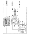
- FIG. 1 is a diagram showing a power management system 100.
- the power management system 100 includes a control device 10, a power storage device unit 20, a switch circuit unit 30, a DC / AC conversion circuit 40, and a DC / AC conversion circuit 50.
- the power management system 100 is connected to the power system 5, the load 6, and the power management company 7.
- the power management system 100 is often installed in a relatively large facility, such as a factory facility or a large hospital.
- the power management system 100 receives power operation cooperation money from the power operation company 7 by an ancillary service according to the charge / discharge command from the power operation company 7, in other words, contributes to obtaining an economic profit amount.
- the power supply source for the load 6 can be the power storage device unit 20.
- the power management system 100 contributes to saving an electricity bill, in other words, obtaining an economical profit amount.
- the electric power system 5 is a system facility for supplying electric power supplied from a power generation company or the like to each consumer in accordance with fluctuations in electric power supply and demand. Electric power supplied from a power generation company or the like is electric power generated by various power generation methods such as hydroelectric power generation, nuclear power generation, hydroelectric power generation, and solar power generation.
- the power system 5 is connected to the second terminal 40 b of the DC / AC conversion circuit 40.
- the load 6 is lighting equipment or electrical equipment used in a facility where the power management system 100 is installed.
- the load 6 is connected to the second terminal 50 b of the DC / AC conversion circuit 50.
- the power management company 7 is a company that operates to balance the demand and supply of power in order to stabilize the power supply from the power system 5 to each consumer.
- the power management company 7 instructs the power storage unit 20 of a plurality of contractors who have made an ancillary service contract with the power management company 7 to charge or discharge with the power system 5. For example, when the power of the power grid 5 is insufficient, the power management company 7 issues a discharge command from the power storage device unit 20 to the power grid 5. In addition, when there is surplus power in the power system 5, the power management company 7 issues a charge command for charging the power storage device unit 20 with surplus power in the power system 5.
- the power operation cooperation money paid from the power management company 7 varies depending on the time zone of the charge / discharge command issued to the power management system 100. Furthermore, the power operation cooperation fee varies depending on the power transaction market such as various situations such as the number of ancillary service subscribers.
- ancillary service contracts with the power management company 7 are regularly recruited. For example, on the day before the implementation date of the ancillary service, charge / discharge schedule information necessary for the implementation date is sent to each collaborator including the power management system 100. Each collaborator makes an ancillary service contract with the power management company 7 if it is determined that the ancillary service can be cooperated on the implementation date.
- the power storage device unit 20 includes secondary batteries 21, 22, and 23 and breakers 24, 25, and 26.
- the secondary batteries 21, 22 and 23 are storage batteries for exchanging electric power between the electric power system 5 and the load 6.
- the secondary batteries 21, 22, and 23 are configured to include a negative electrode made of a carbon material, an electrolytic solution for moving lithium ions, and a positive electrode active material capable of reversibly taking in and out lithium ions.
- the secondary battery 21 has a positive terminal 21a and a negative terminal 21b.
- the positive terminal 21a of the secondary battery 21 is connected to the second terminal 24b of the breaker 24, and the negative terminal 21b is grounded. Further, the secondary battery 21 is charged and discharged by the control device 10 so that the SOC (State Of Charge) indicating the storage state corresponding to the storage amount falls within a predetermined range (for example, 20% to 80%). Made. Since the secondary batteries 22 and 23 have the same configuration as the secondary battery 21, a detailed description thereof is omitted.
- the breaker 24 is a device that cuts off the connection between the secondary battery 21 and the power system 5 and the load 6 under the control of the control device 10 when it is necessary to protect the secondary battery 21.
- the breaker 24 has a first terminal 24 a and a second terminal 24 b, the first terminal 24 a is connected to the first terminal 31 a of the switch circuit 31, and the second terminal 24 b is the positive terminal 21 a of the secondary battery 21. Connected to. Since the breakers 25 and 26 have the same configuration as the breaker 24, detailed description thereof is omitted.
- the switch circuit unit 30 includes a switch circuit 31, a switch circuit 32, and a switch circuit 33.
- the switch circuit 31 is a switching circuit that switches a power exchange destination with the secondary battery 21 to the power system 5 or the load 6 under the control of the control device 10.
- the switch circuit 31 includes a first terminal 31a, a second terminal 31b, and a third terminal 31c.
- the first terminal 31 a is connected to the first terminal 24 a of the breaker 24.
- the second terminal 31 b is connected to the first terminal 40 a of the DC / AC conversion circuit 40.
- the second terminal 31 c is connected to the first terminal 50 a of the DC / AC conversion circuit 50.
- the second terminals 31 b, 32 b, 33 b of the switch circuits 31, 32, 33 are made common at the connection point 34 and connected to the first terminal 40 a of the DC / AC conversion circuit 40. Further, the third terminals 31 c, 32 c, 33 c of the switch circuits 31, 32, 33 are made common at the connection point 35 and connected to the first terminal 50 a of the DC / AC conversion circuit 50.
- the DC / AC conversion circuit 40 is a power conversion circuit that performs power conversion between DC power and AC power.
- the DC / AC conversion circuit 40 has a first terminal 40a and a second terminal 40b.
- the first terminal 40 a is connected to the connection point 34, and the second terminal 40 b is connected to the power system 5.
- the DC / AC conversion circuit 50 is a power conversion circuit that performs power conversion between DC power and AC power.
- the DC / AC conversion circuit 50 has a first terminal 50a and a second terminal 50b.
- the first terminal 50 a is connected to the connection point 35, and the second terminal 50 b is connected to the power system 5.
- a DC / DC conversion circuit is used instead of the DC / AC conversion circuit 50.
- control device 10 Based on the charge / discharge instruction from the power management company 7 and the required power from the load 6, the control device 10 controls the exchange of power between the power storage device unit 20, the power system 5 and the load 6.
- the control device 10 includes a determination processing unit 12, an SOC adjustment processing unit 13, a change processing unit 14, a switching processing unit 16, and a cutoff processing unit 18.
- Each function of the control device 10 may be configured by hardware or software.
- the determination processing unit 12 replaces the secondary batteries 21, 22, and 23 of the power storage device unit 20 with the power grid 5 based on a predetermined parameter, for example, an economic profit amount that is expected to be obtained by charging and discharging.
- a predetermined parameter for example, an economic profit amount that is expected to be obtained by charging and discharging.
- the decision processing unit 12 acquires the charging / discharging schedule information sent from the power management company 7 on the day before the implementation date of the ancillary service.
- the determination processing unit 12 associates each time zone on the implementation date of the past ancillary service corresponding to the implementation date with the power operation cooperation money in that time zone.
- the decision processing unit 12 calculates a system-side predicted profit amount that is a predicted value of an economic profit amount obtained when cooperation for charge / discharge control is performed on the power system 5. calculate.
- the determination processing unit 12 calculates a load side predicted profit amount that is a predicted value of an economic profit amount obtained when power is exchanged between the power storage device unit 20 and the load 6.
- Information to be considered as the load-side predicted profit amount includes a profit amount obtained by using the power storage device 20 as a power supply source for the load 6 instead of the commercial power source connected to the power system 5.
- a power storage device instead of a commercial power source connected to the power system 5 as a power supply source to the load 6 at the peak of the required power of the load 6 that changes every moment
- Information that should be considered as the load-side predicted profit amount is stored in the database as past load-side profit amount information and the like.
- the determination processing unit 12 determines a ratio for exchanging power between the power storage device unit 20 and the power system 5 and the load 6 by comparing the system side predicted profit amount and the load side predicted profit amount. To do. Specifically, the determination processing unit 12 uses the secondary batteries 21, 22, and 23 of the power storage device unit 20 as two power storage units for a power system 5 and a load power storage unit for a load 6. Assign to groups. As an example, the determination processing unit 12 assigns the secondary batteries 21 and 22 as power storage units for the power system 5 and the secondary battery 23 as load power storage units for the load 6. Then, the decision processing unit 12 replies to the power management company 7 that an ancillary service contract is to be made.
- the system side predicted profit amount and the load side predicted profit amount will be described as parameters for assigning the power storage unit for the system and the power storage unit for the load, but other factors can be taken into consideration.
- the SOC adjustment processing unit 13 allows the SOC of the secondary batteries 21, 22, and 23 to start appropriate charge / discharge control. To control. Specifically, at the start of the ancillary service, each secondary battery 21, 22, 23 has an appropriate SOC so that each secondary battery from the assignment determination time by the determination processing unit 12 to the start time of the ancillary service is determined. The charge / discharge control for the secondary batteries 21, 22, 23 is adjusted.
- the change processing unit 14 performs charge / discharge control between the power storage device unit 20 and the power system 5 in response to a charge / discharge command from the power management company 7 and requests for the load 6.
- the discharge control from the power storage device unit 20 to the load 6 is performed according to the electric power.
- the secondary batteries 21 and 22 are assigned as power storage units for the power system 5 and the secondary battery 23 is assigned as a load power storage unit for the load 6.
- the change processing unit 14 performs charge / discharge control between the secondary batteries 21 and 22 and the power system 5 according to the charge / discharge command from the power management company 7, and responds to the required power of the load 6. Then, discharge control from the secondary battery 23 to the load 6 is performed.
- the change processing unit 14 also determines whether or not the ancillary service for the day has ended.
- the change processing unit 14 performs the power storage unit for the system and the power storage unit for the load based on the parameter information. Change the part assignment. For example, an electricity bill, in other words, a charge / discharge command from the power management company 7, the SOC of the secondary batteries 21, 22, and 23, and a power supply source to the load 6 are commercial power sources connected to the power system 5. Then, considering the economic loss, the change processing unit 14 can change the allocation of the grid power storage unit and the load power storage unit.
- the secondary batteries 21 and 22 are assigned as power storage units for the power system 5, and the secondary battery 23 is assigned as the load power storage unit for the load 6.
- the secondary battery 22 can be changed as a load power storage unit for the load 6.
- the switching processing unit 16 has a function of performing switching control of the switch circuit unit 30.
- the secondary batteries 21 and 22 are assigned as power storage units for the power system 5 and the secondary battery 23 is assigned as a load power storage unit for the load 6.
- the switching processing unit 16 performs switching so that the first terminal 31a of the switch circuit 31 is connected to the second terminal 31b.
- the switching processing unit 16 performs switching so that the first terminal 32a of the switch circuit 32 is connected to the second terminal 32b.
- the switching processing unit 16 performs switching so that the first terminal 33a of the switch circuit 33 is connected to the third terminal 33c.
- the cutoff processing unit 18 has a function of performing cutoff control on the connection between the secondary batteries 21, 22, 23 and the power system 5 and the load 6. For example, when the SOC indicating the storage state of the secondary battery 22 is out of a predetermined range (for example, 20% to 80%), the breaker 25 is controlled to be cut off in order to protect the secondary battery 22. To do.
- a predetermined range for example, 20% to 80%
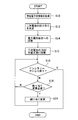
- FIG. 2 is a flowchart showing a procedure for providing an ancillary service by the power management system 100.
- the control device 10 of the power management system 100 acquires the charge / discharge schedule information sent from the power management company 7 as information necessary for performing ancillary service on the next day (S10). This process is realized by the function of the determination processing unit 12 of the control device 10.
- the control device 10 determines the rate of power exchange between the power storage device unit 20 and the power system 5 and the load 6. Specifically, the system side predicted profit amount and the load side predicted profit amount are compared, and from the viewpoint of the economic profit amount, the control device 10 replaces the secondary batteries 21, 22, and 23 of the power storage device unit 20. Then, the power storage unit for the power system 5 and the power storage unit for the load 6 are allocated as a group (S12). This process is realized by the function of the determination processing unit 12 of the control device 10. From the viewpoint of the economic profit amount, for example, the grid power storage unit and the load power storage unit are allocated so that the sum of the system side predicted profit amount and the load side predicted profit amount is maximized.
- control device 10 sends a reply to the effect that an ancillary service contract is made to the power management company 7 (S14). This process is realized by the function of the determination processing unit 12 of the control device 10.
- the SOC of the secondary batteries 21, 22, and 23 is set to an appropriate SOC between the time of the assignment decision and the start time of the ancillary service.
- Charge / discharge control is performed (S15). This process is realized by a function in the SOC adjustment processing unit 13 of the control device 10.
- the control device 10 performs charge / discharge control between the power storage device unit 20 and the power system 5 in accordance with a charge / discharge command from the power management company 7, and loads 6
- the discharge control from the power storage device unit 20 to the load 6 is performed according to the required power.
- step S16 If it is determined in step S16 that the ancillary service has not ended, it is determined whether the allocation of the secondary batteries 21, 22, 23 performed in step S12, in other words, the grouping needs to be changed. Is determined (S18).
- This step is realized by the function of the change processing unit 14 of the control device 10.
- the total expected profit that is the sum of the grid-side predicted profit amount and the load-side predicted profit amount is actually the charge / discharge command from the power management company 7. If the total amount of profit that can be acquired during the implementation of the ancillary service deviates greatly due to the small amount, for example, if it deviates by 5% from the total expected profit, it is determined that a change is necessary.
- step S18 if it is determined that the allocation of the secondary batteries 21, 22, 23 needs to be changed, the charge / discharge command from the power management company 7, the SOC of the secondary batteries 21, 22, 23, and the load 6 are determined.
- the control device 10 changes the allocation of the secondary batteries 21, 22, and 23. (S20).
- This step is realized by the function of the change processing unit 14 of the control device 10.
- the charge / discharge command from the power management company 7 is small, the allocation is changed so that the total economic profit is improved.
- any of the secondary batteries 21, 22, and 23 is out of a predetermined range and needs to protect the secondary battery, the reduction of the total economic profit is minimized. Make assignment changes.
- the process returns to S16 again.
- the system side predicted profit amount and the load side predicted profit amount are compared, and the sum of the system side predicted profit amount and the load side predicted profit amount is maximized.
- the secondary batteries 21, 22, and 23 of the power storage device unit 20 can be allocated to the power storage unit for the power system 5 and the load power storage unit for the load 6 in groups. Thereby, the secondary batteries 21, 22, and 23 of the power storage device unit 20 are appropriately allocated, and charging / discharging is performed between the power storage device 20 and the power system 5 and between the power storage device 20 and the load 6.
- the secondary batteries 21, 22, and 23 can be used effectively.
- Acquiring power management cooperation money provided by the power management company 7 through the ancillary service provides economic benefits, and stores the power supply source for the load 6 instead of the commercial power source connected to the power system 5 By using the device unit 20, it is possible to obtain an economic advantage by saving the electricity bill.
- the allocation of the secondary batteries 21, 22, and 23 is temporarily performed based on the predicted profit amount, for example, on the actual implementation date of the ancillary service, for example, there are few charge / discharge commands from the power management company 7 If so, the allocation can be changed to improve the total economic profit.
- the SOC of any of the secondary batteries 21, 22 and 23 is out of the predetermined range and the secondary battery needs to be protected, the allocation of the economic profit is minimized. Changes can also be made. Thereby, since the allocation of the power storage unit for the system and the power storage unit for the load can be reorganized according to the actual operation status, the secondary batteries 21, 22, 23 of the power storage device unit 20 can be used more effectively. Can do. For example, when the actual cost is different from the system-side predicted profit amount and the load-side predicted profit amount, the allocation of the power storage unit for the system and the power storage unit for the load is appropriately changed according to the actual cost It is good.
- the charge / discharge schedule information sent from the power management company 7 is acquired, and the system-side predicted profit amount is compared with the load-side predicted profit amount.
- an ancillary service contract may not be made. That is, all the secondary batteries 21, 22, and 23 of the power storage device unit 20 may be assigned as load power storage units for the load 6.
- an ancillary service contract may be made, and at this time, all the secondary batteries 21, 22, and 23 of the power storage device unit 20 may be assigned as power storage units for the power system 5.
- the allocation determination of the power storage unit for the system and the power storage unit for the load is performed by using the secondary batteries 21, 22, and 23 as the system power storage unit for the power system 5, for example. 22 is assigned, and the secondary battery 23 is assigned as a load power storage unit for the load 6, so that the secondary battery unit is divided into two groups and assigned.
- the determination of the allocation is not limited to the grouping of the secondary battery units, and for example, within the range of 20 to 40% and 60 to 80% of the SOC for each of the secondary batteries 21, 22, and 23. May be allocated as a load power storage unit for the load 6, and within a range of 40% to 60% may be allocated as a power storage unit for the power system 5.
- the secondary side is considered in consideration of the grid side predicted profit amount and the load side predicted profit amount. It has been described that the assignment of the power storage unit for the system and the power storage unit for the load to the batteries 21, 22, 23 is determined.
- the charge / discharge schedule information is not limited to being sent on the day before the implementation date of the ancillary service, and is naturally sent immediately before the implementation disclosure time, for example, one hour before. May be.
- the allocation of the power storage unit for the system and the power storage unit for the load to the secondary batteries 21, 22, and 23 is determined in consideration of the system-side predicted profit amount and the load-side predicted profit amount. It was explained as a change. However, the assignment may be determined and the assignment may be changed in consideration of other information. For example, the fluctuation status of the power operation cooperation money in the power trading market during the implementation of the ancillary service may be taken into consideration, and the electricity bill which varies depending on each region and time zone may be taken into consideration. Economic benefits obtained by selling the power generated by the power storage device unit 20 may be taken into account.
- the determination of the allocation of the power storage unit for the system and the power storage unit for the load with respect to the secondary batteries 21, 22 and 23 and the change of the allocation may be performed in consideration of other than the viewpoint of the economic profit amount.
- the state of the secondary batteries 21, 22, and 23 of the unit 20 may be considered.
- a small amount of power is exchanged between the power storage device unit 20 and the power system 5 in a short cycle (for example, once every 2 seconds or 4 seconds).
- the power is exchanged between the power storage device unit 20 and the load 6 for a long period of time compared to that and exchanges a large amount of power.
- the secondary batteries 21, 22, and 23 assigned thereto have a long battery life. It is preferable that the amount of stored electricity is not so large (for example, SOC is 60%). On the other hand, when power is supplied to the load 6, the speed at which the life of the battery deteriorates is slower than that of the ancillary service, and a larger amount of power can be supplied to supply a large amount of power. As for 21, 22, and 23, it is preferable that the amount of stored electricity is as large as possible, and it can be said that the battery life may be short.
- the determination processing unit 12 replaces the secondary batteries 21, 22, and 23 of the power storage device unit 20 with the grid power storage unit and the load 6 for the power system 5 based on the state of the secondary batteries 21, 22, and 23. May be divided and assigned to two groups of power storage units for loads.
- the states of the secondary batteries 21, 22, and 23 for example, the current battery remaining amount, the appropriate charge amount, the predicted future battery remaining amount, the number of times of charging / discharging based on past experience, the battery life, the past ancillary You may consider the allocation history to a service.
- the battery life may be estimated by the determination processing unit 12 from the appropriate charge amount and the number of times of charging based on past experience.
- the correspondence between the integrated value of the past charge / discharge capacity and the internal resistance and the battery life is obtained in advance by measurement, simulation, or the like, and a table or a graph defining the correspondence is stored in the determination processing unit 12,
- the determination processing unit 12 may guess by referring to it.
- the determination processing unit 12 has a predetermined threshold value of the storage amount of the secondary batteries 21, 22, and 23 of the power storage device unit 20 based on the remaining battery level at the present time and the predicted remaining battery level.
- a power storage unit for load for load 6 may be larger than the value, and a power storage unit for system for power system 5 may be used as the rest.
- the determination processing unit 12 is, for example, based on the life of the battery, among the secondary batteries 21, 22, and 23, a power storage unit for the power system 5 that has a battery life longer than a predetermined threshold value The remainder may be a load power storage unit for the load 6.
- the secondary battery that has been assigned to the ancillary service in the past is prioritized for the power system 5.
- the power storage unit may be a load power storage unit for the load 6 and may not be continuously allocated to the ancillary service.
- elements other than the SOC of the secondary batteries 21, 22, and 23 may be considered, and for example, real-time demand prediction of a customer or the like connected to the power system 5 can be considered.
Abstract
蓄電池を有効活用したアンシラリーサービスのための制御装置を提供する。 蓄電装置部20と電力系統5との間の充電又は放電及び蓄電装置部20から負荷6への放電の制御を行う制御装置10であって、当該制御による経済的な利益額又は蓄電装置部20に含まれる二次電池21,22,23の状態の少なくとも一方に基づいて、二次電池21,22,23を、電力系統5への放電制御のための系統用蓄電部と、負荷6への放電制御のための負荷用蓄電部と、に割り当てて系統用蓄電部から電力系統5への放電及び負荷用蓄電部から負荷6への放電の制御を行う。
Description
本発明は、制御装置に係り、特に、蓄電装置部に対する充放電制御を行う制御装置に関する。
発電会社等に接続される電力系統を用い、安定して各需要家に対して電力供給するためには、電力系統の運用にあたって、電力の需要と供給のバランスを取る必要がある。例えば、欧米等では、当該電力系統の安定的な運用を図ることを目的として設立された電力運用会社が存在する。欧米等において、蓄電装置を所有する者が、この電力運用会社との間で契約を行なって、当該電力運用会社からの電力充放電指示に応じて充放電を行なうことで電力運用協力金が支給されるサービスである、いわゆるアンシラリーサービスが実施されている。
特許文献1には、二次電池を用いたアンシラリーサービス提供方法として、二次電池を設置しアンシラリーサービスの分担を許容する需要家に対して、予め設定された期間の二次電池のアンシラリーサービス提供量または提供能力を積算して記録することが述べられている。
ところで、上記電力運用会社との間でアンシラリーサービスの契約を行うと、当該契約者は、電力運用会社からの電力充放電指示に対応することが必要となる。その電力充放電指示に対応するために、当該契約者は予め十分な容量の蓄電装置を備えている。しかし、電力運用会社からの充放電指示の状況によっては、全く使用せずに存在している蓄電装置の容量もあるため、当該蓄電装置を有効に利用することが望まれる。
本発明の目的は、電力系統及び負荷と蓄電装置と間で電力のやりとりを行なう場合に、蓄電装置をより有効に利用することを可能とする制御装置を提供することである。
本発明に係る制御装置は、蓄電装置と電力系統との間の充電又は放電及び蓄電装置から負荷への放電の制御を行う制御装置であって、当該制御による経済的な利益額又は蓄電装置に含まれる蓄電池の状態の少なくとも一方に基づいて、蓄電池を、電力系統への放電制御のための系統用蓄電部と、負荷への放電制御のための負荷用蓄電部と、に割り当てて、系統用蓄電部から電力系統への放電及び負荷用蓄電部から負荷への放電の制御を行うことを特徴とする。
上記構成の制御装置によれば、所定のパラメータに基づいて、蓄電装置に含まれる蓄電池を、電力系統への放電制御のための系統用蓄電部と、負荷への放電制御のための負荷用蓄電部と、に割り当てて電力系統及び負荷に電力を供給させる。これにより、種々のパラメータに基づいて、系統用蓄電部と負荷用蓄電部とに割り当てることができるため、蓄電装置をより有効に利用することができる。
以下に図面を用いて、本発明に係る実施の形態を詳細に説明する。アンシラリーサービスは、電力系統を用いて各需要家に対して安定した電力供給のためにとる様々なサービスを指すことが多い。以下においては、アンシラリーサービスとして、電力運用会社の要望に応じて、電力系統に対して蓄電装置を充放電制御することを示すものとする。
また、以下では、蓄電池としてリチウムイオン電池を説明するが、これ以外の二次電池であってもよい。例えば、ニッケル水素電池、ニッケルカドミウム電池等であってもよい。
また、以下では、全ての図面において同様の要素には同一の符号を付し、重複する説明を省略する。また、本文中の説明においては、必要に応じそれ以前に述べた符号を用いるものとする。
図1は、電力管理システム100を示す図である。電力管理システム100は、制御装置10と、蓄電装置部20と、スイッチ回路部30と、DC/AC変換回路40と、DC/AC変換回路50を備える。電力管理システム100は、電力系統5と、負荷6と、電力運用会社7とに接続されている。
電力管理システム100は、比較的大規模な施設に設置されることが多く、例えば、工場施設や大病院等に設置される。電力管理システム100は、電力運用会社7からの充放電指令に応じたアンシラリーサービスによって電力運用会社7からの電力運用協力金を受け取る、換言すれば経済的な利益額を得ることに寄与する。さらに、蓄電装置部20から負荷6へ放電を行なうことで、負荷6に対する電力供給源を蓄電装置部20とすることができる。これにより、電力管理システム100は、電気代を節約、換言すれば経済的な利益額を得ることに寄与する。
電力系統5は、発電会社等から供給される電力を、電力需給の変動等に合わせて、各需要家に対して電力供給するための系統設備である。発電会社等から供給される電力は、水力発電、原子力発電、水力発電、太陽光発電等の様々な発電方式によって発電された電力である。電力系統5は、DC/AC変換回路40の第2端子40bと接続されている。
負荷6は、電力管理システム100が設置される施設内に用いられる照明設備や電気機器等である。負荷6は、DC/AC変換回路50の第2端子50bと接続されている。
電力運用会社7は、電力系統5から各需要家への電力供給を安定させるために、電力の需要と供給のバランスをとるように運用を行なう会社である。電力運用会社7は、当該電力運用会社7との間でアンシラリーサービス契約を行った複数の契約者の蓄電装置部20に対して、電力系統5との間で充電又は放電の指令を行う。例えば、電力運用会社7は、電力系統5の電力が不足する場合には蓄電装置部20から電力系統5への放電指令を行う。また、電力運用会社7は、電力系統5の電力が余っている場合には、電力系統5における余剰電力を蓄電装置部20に充電させる充電指令を行う。
ここで、電力運用会社7から支払われる電力運用協力金は、電力管理システム100に対してなされる充放電指令の時間帯によって変動する。さらには、当該電力運用協力金は、アンシラリーサービスの契約者数等の種々の状況等の電力取引市場に応じて変動する。
電力運用会社7との間におけるアンシラリーサービス契約は、定期的に募集がなされる形態が多い。例えば、アンシラリーサービスの実施日の前日において、当該実施日に必要な充放電予定情報が電力管理システム100を含めた各協力者に送付される。各協力者は、当該実施日にアンシラリーサービスによる協力が可能であると判断すれば、電力運用会社7との間でアンシラリーサービス契約を行なう。
蓄電装置部20は、二次電池21,22,23と、ブレーカ24,25,26とを含む。二次電池21,22,23は、電力系統5及び負荷6との間で電力のやりとりを行なうための蓄電池である。二次電池21,22、23は、炭素物質で構成された負極と、リチウムイオンが移動するための電解液と、リチウムイオンを可逆的に出し入れできる正極活物質とを含んで構成される。
二次電池21は、正極側端子21aと負極側端子21bを有している。二次電池21の正極側端子21aは、ブレーカ24の第2端子24bに接続され、負極側端子21bは接地されている。また、二次電池21は、制御装置10によって、蓄電量に対応した蓄電状態を示すSOC(State Of Charge)が所定の範囲内(例えば、20%~80%)に入るように充放電制御がなされる。二次電池22,23は、二次電池21と同様の構成を有するため詳細な説明は省略する。
ブレーカ24は、二次電池21を保護する必要がある時に、制御装置10の制御によって、二次電池21と電力系統5及び負荷6との接続を遮断する装置である。ブレーカ24は、第1端子24aおよび第2端子24bを有しており、第1端子24aがスイッチ回路31の第1端子31aに接続され、第2端子24bが二次電池21の正極側端子21aに接続される。ブレーカ25,26は、ブレーカ24と同様の構成を有するため詳細な説明は省略する。
スイッチ回路部30は、スイッチ回路31と、スイッチ回路32と、スイッチ回路33とを有する。スイッチ回路31は、制御装置10の制御によって、二次電池21との間の電力のやり取り先を電力系統5あるいは負荷6に切り替える切替回路である。スイッチ回路31は、第1端子31aと第2端子31bと第3端子31cとを有する。第1端子31aは、ブレーカ24の第1端子24aと接続されている。第2端子31bは、DC/AC変換回路40の第1端子40aと接続されている。第2端子31cは、DC/AC変換回路50の第1端子50aと接続されている。
ここで、スイッチ回路31の第1端子31aが第2端子31bに接続されている場合には、二次電池21と電力系統5との間で充放電制御がなされる。一方、スイッチ回路31の第1端子31aが第3端子31cに接続されている場合には、二次電池21と負荷6との間で充放電制御がなされる。スイッチ回路32,32は、スイッチ回路31と同様の構成を有するため詳細な説明は省略する。
スイッチ回路31,32,33の第2端子31b,32b,33bは、接続点34で共通にされてDC/AC変換回路40の第1端子40aと接続されている。また、スイッチ回路31,32,33の第3端子31c,32c,33cは、接続点35で共通にされてDC/AC変換回路50の第1端子50aと接続されている。
DC/AC変換回路40は、直流電力と交流電力との間の電力変換を行なう電力変換回路である。DC/AC変換回路40は、第1端子40aと第2端子40bとを有する。DC/AC変換回路40は、第1端子40aが接続点34と接続され、第2端子40bが電力系統5と接続されている。
DC/AC変換回路50は、直流電力と交流電力との間の電力変換を行なう電力変換回路である。DC/AC変換回路50は、第1端子50aと第2端子50bとを有する。DC/AC変換回路50は、第1端子50aが接続点35と接続され、第2端子50bが電力系統5と接続されている。負荷6が直流駆動の場合には、DC/AC変換回路50に替えてDC/DC変換回路が用いられる。
電力運用会社7からの充放電指示及び負荷6からの要求電力に基づいて、制御装置10は、蓄電装置部20と、電力系統5及び負荷6との間の電力のやりとりを制御する。制御装置10は、決定処理部12と、SOC調整処理部13と、変更処理部14と、切替処理部16と、遮断処理部18とを有する。制御装置10の各機能は、ハードウェアによって構成してもよく、ソフトウェアによって構成してもよい。
決定処理部12は、所定のパラメータ、例えば、充放電によって得ることができると予測される経済的な利益額に基づいて、蓄電装置部20の二次電池21,22,23を、電力系統5のための系統用蓄電部と負荷6のための負荷用蓄電部との2つのグループに分けて割り当てる。
このため、決定処理部12は、アンシラリーサービスの実施日の前日に、電力運用会社7から送付される充放電予定情報を取得する。この充放電予定情報に基づいて、決定処理部12は、該実施日に対応する過去のアンシラリーサービスの実施日における各時間帯と、その時間帯における電力運用協力金とが対応づけられた過去の系統側利益情報を保存するデータベースとから、当該実施日にアンシラリーサービスに協力した場合に取得できる電力運用協力金情報を受け取る。この電力運用協力金情報に基づいて、決定処理部12は、電力系統5に対して充放電制御の協力を行った際に得られる経済的な利益額の予測値である系統側予測利益額を算出する。
このため、決定処理部12は、アンシラリーサービスの実施日の前日に、電力運用会社7から送付される充放電予定情報を取得する。この充放電予定情報に基づいて、決定処理部12は、該実施日に対応する過去のアンシラリーサービスの実施日における各時間帯と、その時間帯における電力運用協力金とが対応づけられた過去の系統側利益情報を保存するデータベースとから、当該実施日にアンシラリーサービスに協力した場合に取得できる電力運用協力金情報を受け取る。この電力運用協力金情報に基づいて、決定処理部12は、電力系統5に対して充放電制御の協力を行った際に得られる経済的な利益額の予測値である系統側予測利益額を算出する。
また、決定処理部12は、蓄電装置部20と負荷6との間で電力のやり取りを行なった場合に得られる経済的な利益額の予測値である負荷側予測利益額を算出する。当該負荷側予測利益額として考慮すべき情報としては、負荷6への電力供給源を電力系統5に接続される商用電源の代わりに蓄電装置部20とすることで得られる利益額がある。当該負荷側利益額として他に考慮すべき情報として、時々刻々変化する負荷6の要求電力のピーク時において、負荷6への電力供給源を電力系統5に接続される商用電源の代わりに蓄電装置部20とするピークカット処理により得られる利益額がある。負荷側予測利益額として考慮すべき情報は、過去の負荷側利益額情報等として上記データベースに保存されている。
系統側予測利益額と負荷側予測利益額とを比較して、決定処理部12は、蓄電装置部20と、電力系統5及び負荷6と、の間の電力のやり取りを行なうための割合を決定する。具体的には、決定処理部12は、蓄電装置部20の二次電池21,22,23を、電力系統5のための系統用蓄電部と負荷6のための負荷用蓄電部との2つのグループに分けて割り当てる。一例として、決定処理部12は、電力系統5のための系統用蓄電部として二次電池21,22を割り当て、負荷6のための負荷用蓄電部として二次電池23を割り当てる。そして、決定処理部12は、電力運用会社7に対してアンシラリーサービスの契約を行なう旨の回答をする。ここでは、系統用蓄電部及び負荷用蓄電部の割り当てを行なうパラメータとして、系統側予測利益額と負荷側予測利益額を説明するがもちろん、その他の要素も考慮することができる。
決定処理部12によってなされた系統用蓄電部及び負荷用蓄電部の割り当てに対応して、SOC調整処理部13は、適正な充放電制御が開始できるように二次電池21,22,23のSOCを制御する。具体的には、アンシラリーサービスの開始時において、各二次電池21,22,23が適正なSOCとなるように、決定処理部12による割り当て決定時からアンシラリーサービスの開始時刻までにおける各二次電池21,22,23に対する充放電制御を調整する。
アンシラリーサービスの実施日において、変更処理部14は、電力運用会社7からの充放電指令に応じて、蓄電装置部20と電力系統5との間における充放電制御を行なうとともに、負荷6の要求電力に応じて、蓄電装置部20から負荷6への放電制御を行う。例えば、電力系統5のための系統用蓄電部として二次電池21,22を割り当て、負荷6のための負荷用蓄電部として二次電池23を割り当てたとする。この場合、電力運用会社7からの充放電指令に応じて、変更処理部14は、二次電池21,22と電力系統5との間における充放電制御を行なうとともに、負荷6の要求電力に応じて、二次電池23から負荷6への放電制御を行う。変更処理部14は、その日のアンシラリーサービスが終了したか否かについても判断する。
決定処理部12によって系統用蓄電部及び負荷用蓄電部の割り当てが決定された後のアンシラリーサービスの実施中において、変更処理部14は、パラメータ情報に基づいて、系統用蓄電部及び負荷用蓄電部の割り当てを変更する。例えば、電力運用会社7からの充放電指令、二次電池21,22,23のSOC、及び負荷6への電力供給源を電力系統5に接続される商用電源とした場合にかかる電気代、換言すれば経済的損失を考慮して、変更処理部14は、系統用蓄電部及び負荷用蓄電部の割り当てを変更することができる。上記の例では、電力系統5のための系統用蓄電部として二次電池21,22を割り当て、負荷6のための負荷用蓄電部として二次電池23を割り当てた。実際のアンシラリーサービスの実施日では、電力運用会社7からの充放電指令が少ないために、二次電池22を負荷6のための負荷用蓄電部として割り当てを変更することもできる。
決定処理部12及び変更処理部14によって割り当てられた系統用蓄電部及び負荷用蓄電部に基づいて、切替処理部16は、スイッチ回路部30を切替制御する機能を有する。上記の例では、電力系統5のための系統用蓄電部として二次電池21,22を割り当て、負荷6のための負荷用蓄電部として二次電池23を割り当てる場合を説明する。切替処理部16は、スイッチ回路31の第1端子31aが第2端子31bと接続するように切り替える。切替処理部16は、スイッチ回路32の第1端子32aが第2端子32bと接続するように切り替える。切替処理部16は、スイッチ回路33の第1端子33aが第3端子33cと接続するように切り替える。
遮断処理部18は、二次電池21,22,23と電力系統5及び負荷6との接続を遮断制御する機能を有する。例えば、二次電池22の蓄電状態を示すSOCが所定の範囲内(例えば、20%~80%)から外れる状態となっているときに、二次電池22を保護するためにブレーカ25を遮断制御する。
上記構成の電力管理システム100の作用について、図1,2を用いて詳細に説明する。図2は、電力管理システム100によるアンシラリーサービスを行なう際の手順を示すフローチャートである。電力管理システム100の制御装置10は、翌日にアンシラリーサービスを行なうために必要な情報であり、電力運用会社7から送付されてくる充放電予定情報を取得する(S10)。この工程は、制御装置10の決定処理部12の機能によって実現される。
次に、制御装置10は、蓄電装置部20と電力系統5及び負荷6との電力のやり取りの割合を決定する。具体的には、系統側予測利益額と負荷側予測利益額とを比較して、経済的な利益額の観点から、制御装置10は、蓄電装置部20の二次電池21,22,23を、電力系統5のための系統用蓄電部と、負荷6のための負荷用蓄電部とにグループ分けして割り当てる(S12)。この工程は、制御装置10の決定処理部12の機能によって実現される。経済的な利益額の観点としては、例えば、系統側予測利益額と負荷側予測利益額との和が最大となるように、系統用蓄電部及び負荷用蓄電部の割り当てを行う。
そして、制御装置10は、電力運用会社7に対して、アンシラリーサービス契約を行なう旨の回答を送付する(S14)。この工程は、制御装置10の決定処理部12の機能によって実現される。
その後、決定処理部12によってなされた割り当てに対応して、上記割り当て決定時からアンシラリーサービスの開始時刻までの間において、二次電池21,22,23のSOCをそれぞれ適正なSOCとなるように充放電制御する(S15)。この工程は、制御装置10のSOC調整処理部13に機能によって実現される。
続いて、アンシラリーサービスの実施日において、制御装置10は、電力運用会社7からの充放電指令に応じて、蓄電装置部20と電力系統5との間における充放電制御を行なうとともに、負荷6の要求電力に応じて、蓄電装置部20から負荷6への放電制御を行う。そして、その日のアンシラリーサービスが終了したか否かについても判断する(S16)。この工程は、制御装置10の変更処理部14の機能によって実現される。S16の工程において、アンシラリーサービスが終了したと判断されれば、END処理へと進む。
S16の工程において、アンシラリーサービスが終了していないと判断されれば、S12の工程において行なわれた二次電池21,22,23の割り当て、換言すれば、グループ分けの変更が必要か否かを判断する(S18)。この工程は、制御装置10の変更処理部14の機能によって実現される。ここで、割り当ての変更が必要か否かの判断基準としては、系統側予測利益額と負荷側予測利益額との和である予想利益総額が、実際に電力運用会社7からの充放電指令が少ないためにアンシラリーサービスの実施中に取得できる利益総額とが大きくずれてしまっている場合、例えば、予想利益総額と5%ずれている場合に変更が必要と判断する。また、二次電池21,22,23のうち、いずれかのSOCが所定の範囲から外れた場合に、その二次電池を割り当てから外す必要があり割り当ての変更が必要と判断する。S18の工程において、二次電池21,22,23の割り当ての変更が必要ないと判断されれば、再びS16へと戻る。
S18の工程において、二次電池21,22,23の割り当ての変更が必要と判断されれば、電力運用会社7からの充放電指令及び二次電池21,22,23のSOC及び負荷6への電力供給源を電力系統5に接続される商用電源とした場合にかかる電気代(経済的な損失)を考慮して、制御装置10は、二次電池21,22,23の割り当ての変更を行なう(S20)。この工程は、制御装置10の変更処理部14の機能によって実現される。ここで、上記の要素から考慮する一例として、電力運用会社7からの充放電指令が少ない状態であれば、経済的な利益総額が改善するように割り当ての変更を行う。また、二次電池21,22,23のうち、いずれかのSOCが所定の範囲から外れて当該二次電池を保護する必要があるときに、経済的な利益総額の減額が最小となるように割り当ての変更を行う。S20の工程の後は、再びS16へと戻る。
上記のように、電力管理システム100によれば、系統側予測利益額と負荷側予測利益額とを比較して、系統側予測利益額と負荷側予測利益額との和が最大となるように、蓄電装置部20の二次電池21,22,23を、電力系統5のための系統用蓄電部と負荷6のための負荷用蓄電部とにグループ分けして割り当てることができる。これにより、蓄電装置部20の二次電池21,22,23をそれぞれ好適に割り当てて、蓄電装置20と電力系統5との間及び蓄電装置20と負荷6との間で充放電を行うことで、有効に二次電池21,22,23を活用することができる。アンシラリーサービスにより電力運用会社7から支給される電力運用協力金を取得することで経済的な利益を得るとともに、負荷6への電力供給源を電力系統5に接続される商用電源の代わりに蓄電装置部20とすることで電気代を節約することで経済的な利益を得ることもできる。
また、予測利益額に基づいて、一旦、二次電池21,22,23の割り当てを行なった後に、実際のアンシラリーサービスの実施日において、例えば、電力運用会社7からの充放電指令が少ない状態であれば、経済的な利益総額が改善するように割り当ての変更を行うことができる。二次電池21,22,23のうちいずれかのSOCが所定の範囲から外れて、当該二次電池を保護する必要があるときに、経済的な利益総額の減額が最小となるように割り当ての変更を行うこともできる。これにより、実際の運用状況に応じて、系統用蓄電部及び負荷用蓄電部の割り当てを再編することができるため、蓄電装置部20の二次電池21,22,23をより有効に活用することができる。例えば、系統側予測利益額及び負荷側予測利益額と、これらの実際の費用が異なる場合に、当該実際の費用に応じて、適宜、系統用蓄電部及び負荷用蓄電部の割り当てを変更するものとしてもよい。
上記では、電力運用会社7から送付されてくる充放電予定情報を取得し、系統側予測利益額と負荷側予測利益額とを比較して、アンシラリーサービス契約を行なうものとして説明したが、当該比較結果によっては、アンシラリーサービス契約を行なわないものとしてもよい。つまり、蓄電装置部20の二次電池21,22,23を全て負荷6のための負荷用蓄電部として割り当ててもよい。上記比較結果によっては、アンシラリーサービス契約を行なって、このとき、蓄電装置部20の二次電池21,22,23を全て電力系統5のための系統用蓄電部として割り当ててもよい。
電力管理システム100によれば、系統用蓄電部及び負荷用蓄電部の割り当て決定は、二次電池21,22,23を、例えば、電力系統5のための系統用蓄電部として二次電池21,22を割り当て、負荷6のための負荷用蓄電部として二次電池23を割り当てるというように、二次電池単位で、2つのグループに分けて割り当てることでなされるものとして説明した。しかし、当該割り当ての決定は、二次電池単位のグループ分けに限らず、例えば、各二次電池21,22,23のそれぞれに対して、SOCの20~40%及び60~80%の範囲内は、負荷6のための負荷用蓄電部として割り当て、40%~60%の範囲内は、電力系統5のための系統用蓄電部として割り当てるものとしてもよい。
電力管理システム100では、アンシラリーサービスの実施日の前日に電力運用会社7から送付されてくる充放電予定情報に基づき、系統側予測利益額と負荷側予測利益額等を考慮して、二次電池21,22,23に対する系統用蓄電部及び負荷用蓄電部の割り当てを決定するものとして説明した。しかし、充放電予定情報はアンシラリーサービスの実施日の前日に送付されてくることには限定されずに、当然ながら、実施開示時刻の直前、例えば、1時間前に送付されてくるものであってもよい。
電力管理システム100では、系統側予測利益額と負荷側予測利益額を考慮して、二次電池21,22,23に対する系統用蓄電部及び負荷用蓄電部の割り当てを決定し、また、その割り当ての変更を行うものとして説明した。しかし、その他の情報を考慮して上記割り当ての決定及びその割り当ての変更を行ってもよい。例えば、アンシラリーサービスの実施中における電力取引市場における電力運用協力金の変動状況を考慮してもよく、各地域や時間帯によって異なる電気代を考慮に入れてもよい。蓄電装置部20によって発電された電力を売電することによって得られる経済的な利益を考慮に入れてもよい。
二次電池21,22,23に対する系統用蓄電部及び負荷用蓄電部の割り当ての決定及びその割り当ての変更は、経済的な利益額の観点以外を考慮して行なってもよく、例えば、蓄電装置部20の二次電池21,22,23の状態を考慮するものとしてもよい。ここで、アンシラリーサービスの場合は、短い周期で(例えば、2秒または4秒に1回)に、小容量の電力のやり取りを蓄電装置部20と電力系統5との間で行う。一方、負荷6に電力を供給する場合は、それに比べると長期間で、また、大容量の電力のやり取りを蓄電装置部20と負荷6の間で行う。
このため、アンシラリーサービスでは、電池の寿命が劣化し易く、また、蓄電量が少なくても対応が可能になるため、これに割り当てる二次電池21,22,23としては、電池の寿命が長いものが好ましく、また、蓄電量があまり多くない(例えば、SOCが60%)ものでも良いと言える。
一方、負荷6に電力を供給する場合は、電池の寿命が劣化する速度は、アンシラリーサービスよりも遅く、また、蓄電量が多いほうが大容量の電力を供給できるので、これに割り当てる二次電池21,22,23としては、蓄電量はできるだけ多いほうが好ましく、また、電池の寿命が短いものでも良いと言える。
そこで、決定処理部12は、二次電池21,22,23の状態に基づいて、蓄電装置部20の二次電池21,22,23を、電力系統5のための系統用蓄電部と負荷6のための負荷用蓄電部との2つのグループに分けて割り当ててもよい。二次電池21,22,23の状態として、例えば、現時点における電池残量、適正充電量、予測される将来の電池残量、過去の経験に基づく充放電回数、電池の寿命、過去のアンシラリーサービスへの割り当て履歴を考慮してもよい。
電池の寿命は、適正充電量や過去の経験に基づく充電回数から決定処理部12が推測してもよい。また、過去の充放電容量の積算値や内部抵抗と電池の寿命の対応関係を予め測定やシミュレーション等で求め、その対応関係を規定したテーブルやグラフを決定処理部12内部に記憶しておき、それを参照することで決定処理部12が推測してもよい。
決定処理部12は、例えば、現時点における電池残量、予測される将来の電池残量に基づき、蓄電装置部20の二次電池21,22,23のうち、蓄電量の値が所定のしきい値より大きいものを負荷6のための負荷用蓄電部とし、残りを電力系統5のための系統用蓄電部としてもよい。また、決定処理部12は、例えば、電池の寿命に基づき、二次電池21,22,23のうち、電池の寿命が所定のしきい値より長いものを電力系統5のための系統用蓄電部とし、残りを負荷6のための負荷用蓄電部としてもよい。また、過去のアンシラリーサービスへの割り当て履歴に基づき、二次電池21,22,23のうち、過去にアンシラリーサービスに割り当てた回数が少ない二次電池を優先して電力系統5のための系統用蓄電部とし、残りを負荷6のための負荷用蓄電部としてもよく、連続してアンシラリーサービスに割り当てないようにしてもよい。
さらに、二次電池21,22,23のSOC以外の要素を考慮してもよく、例えば、電力系統5に接続される需要家等のリアルタイム需要予測を考慮することもできる。
5 電力系統、6 負荷、7 電力運用会社、10 制御装置、12 決定処理部、13 SOC調整処理部、14 変更処理部、16 切替処理部、18 遮断処理部、20 蓄電装置部、21,22,23 二次電池、21a 正極側端子、21b 負極側端子、24,25,26 ブレーカ、24a 第1端子、24b 第2端子、30 スイッチ回路部、31,32,33 スイッチ回路、31a,32a,33a 第1端子、31b,32b,33b 第2端子、31c,32c,33c 第3端子、34,35 接続点、40 DC/AC変換回路、40a 第1端子、40b 第2端子、50 DC/AC変換回路、50a 第1端子、50b 第2端子、100 電力管理システム。
Claims (11)
- 蓄電装置と電力系統との間の充電又は放電及び前記蓄電装置から負荷への放電の制御を行う制御装置であって、
前記制御による経済的な利益額又は前記蓄電装置に含まれる蓄電池の状態の少なくとも一方に基づいて、前記蓄電池を、前記電力系統への放電制御のための系統用蓄電部と、前記負荷への放電制御のための負荷用蓄電部と、に割り当てて、前記系統用蓄電部から前記電力系統への放電及び前記負荷用蓄電部から前記負荷への放電の制御を行うことを特徴とする制御装置。 - 請求項1に記載の制御装置において、
前記蓄電装置は、複数の蓄電池を含み、
前記複数の蓄電池は、前記系統用蓄電部として割り当てられた蓄電池と前記負荷用蓄電部として割り当てられた蓄電池とにグループ分けされることを特徴とする制御装置。 - 請求項1に記載の制御装置において、
前記蓄電池の蓄電量のうち、第1の割合が前記系統用蓄電部として割り当てられ、第2の割合が前記負荷用蓄電部として割り当てられることを特徴とする制御装置。 - 請求項1から請求項3のいずれか1に記載の制御装置において、
外部からの充放電指令に基づいて、前記電力系統と前記蓄電装置との間の充放電制御を行い、
前記負荷の要求電力に基づいて、前記蓄電装置から前記負荷への放電制御を行うことを特徴とする制御装置。 - 請求項4に記載の制御装置において、
前記制御による経済的な利益額に基づいて前記系統用蓄電部及び前記負荷用蓄電部の割り当てを一旦行った後に所定の時刻から所定の期間内において、前記外部からの充放電指令及び前記負荷の要求電力に基づいて充放電制御を行っている場合に、
前記蓄電池の蓄電量と、商用電源から前記負荷へ電力供給されたときの経済的損失とに基づいて、前記系統用蓄電部及び前記負荷用蓄電部の割り当てを変更することを特徴とする制御装置。 - 請求項1から請求項5のいずれか1に記載の制御装置において、
前記制御による経済的な利益額は、前記電力系統と前記蓄電装置との間で充放電するときの経済的利益額の予測値である系統側予測利益額と、前記蓄電装置から前記負荷へ放電するときの経済的利益額の予測値である負荷側予測利益額を含み、
前記制御装置は、前記系統側予測利益額及び前記負荷側予測利益額に基づいて、前記系統用蓄電部及び前記負荷用蓄電部の割り当てを行うことを特徴とする制御装置。 - 請求項6に記載の制御装置において、
前記系統側予測利益額は、過去において前記電力系統と前記蓄電装置との間で充放電制御を行なったときに取得した過去の利益額情報に基づいた経済的収益額の予測値であることを特徴とする制御装置。 - 請求項6または請求項7に記載の制御装置において、
前記負荷側予測利益額は、前記負荷への電力供給源を商用電源の代わりに前記蓄電装置としたときに取得した過去の利益額情報に基づいた経済的利益額の予測値であることを特徴とする制御装置。 - 請求項6または請求項7に記載の制御装置において、
前記負荷側予測利益額は、前記負荷の要求電力のピーク時に電力供給源を商用電源の代わりに前記蓄電装置とするピークカット処理を行なったときに取得した過去の利益額情報に基づいた経済的利益額の予測値であることを特徴とする制御装置。 - 請求項6から請求項9のいずれか1に記載の制御装置において、
前記系統用蓄電部及び前記負荷用蓄電部の割り当てを一旦行った後に所定の時刻から所定の期間内において、前記外部からの充放電指令及び前記負荷の要求電力に基づいて充放電制御を行う場合に、
前記所定の時刻において、前記蓄電装置が適正な容量値に対応する蓄電量となるように前記蓄電装置の前記蓄電池に対する充放電制御を行うことを特徴とする制御装置。 - 請求項6から請求項10のいずれか1に記載された制御装置において、
前記系統用蓄電部及び前記負荷用蓄電部の割り当てを一旦行った後に所定の時刻から所定の期間内において、前記外部からの充放電指令及び前記負荷の要求電力に基づいて充放電制御を行っている場合に、
前記負荷側予測利益額及び前記系統側予測利益額がそれぞれ実際の利益額と異なる場合に、前記実際の利益額に応じて、前記系統用蓄電部及び前記負荷用蓄電部の割り当てを変更することを特徴とする制御装置。
Priority Applications (3)
| Application Number | Priority Date | Filing Date | Title |
|---|---|---|---|
| JP2012541849A JP5909672B2 (ja) | 2010-11-02 | 2011-10-31 | 制御装置 |
| EP11837971.8A EP2637277A4 (en) | 2010-11-02 | 2011-10-31 | Control apparatus |
| US13/850,625 US20130229057A1 (en) | 2010-11-02 | 2013-03-26 | Control apparatus |
Applications Claiming Priority (2)
| Application Number | Priority Date | Filing Date | Title |
|---|---|---|---|
| JP2010246734 | 2010-11-02 | ||
| JP2010-246734 | 2010-11-02 |
Related Child Applications (1)
| Application Number | Title | Priority Date | Filing Date |
|---|---|---|---|
| US13/850,625 Continuation US20130229057A1 (en) | 2010-11-02 | 2013-03-26 | Control apparatus |
Publications (1)
| Publication Number | Publication Date |
|---|---|
| WO2012060321A1 true WO2012060321A1 (ja) | 2012-05-10 |
Family
ID=46024434
Family Applications (1)
| Application Number | Title | Priority Date | Filing Date |
|---|---|---|---|
| PCT/JP2011/075060 WO2012060321A1 (ja) | 2010-11-02 | 2011-10-31 | 制御装置 |
Country Status (4)
| Country | Link |
|---|---|
| US (1) | US20130229057A1 (ja) |
| EP (1) | EP2637277A4 (ja) |
| JP (1) | JP5909672B2 (ja) |
| WO (1) | WO2012060321A1 (ja) |
Cited By (5)
| Publication number | Priority date | Publication date | Assignee | Title |
|---|---|---|---|---|
| JP2015176304A (ja) * | 2014-03-14 | 2015-10-05 | パナソニックIpマネジメント株式会社 | 蓄電池制御方法、および、蓄電池制御装置 |
| JP2017112655A (ja) * | 2015-12-14 | 2017-06-22 | 株式会社日立製作所 | 電力貯蔵システム管理装置、電力貯蔵システム管理方法、電力貯蔵システム |
| JP2018023282A (ja) * | 2014-03-27 | 2018-02-08 | 京セラ株式会社 | 電力管理装置、電力管理システム及び電力管理方法 |
| JP2019212514A (ja) * | 2018-06-06 | 2019-12-12 | 三菱重工業株式会社 | 蓄電システムの運用評価方法及び蓄電システムの運用評価装置 |
| JP7444584B2 (ja) | 2019-11-13 | 2024-03-06 | 京セラ株式会社 | 電力制御システム、電力制御装置、電力制御方法およびプログラム |
Families Citing this family (9)
| Publication number | Priority date | Publication date | Assignee | Title |
|---|---|---|---|---|
| WO2014019607A1 (en) * | 2012-07-31 | 2014-02-06 | Siemens Aktiengesellschaft | Device for an optimized operation of a local storage system in an electrical energy supply grid with distributed generators, distributed storage systems and loads |
| EP2721715B1 (en) * | 2012-07-31 | 2017-07-05 | Caterva GmbH | Method for the overall optimization of the operation of distributed storage devices in an electrical power supply system having distributed generators and loads |
| KR20140023125A (ko) | 2012-08-17 | 2014-02-26 | 엘지전자 주식회사 | 에너지 저장장치, 전력 관리 장치, 이동 단말기 및 그 동작방법 |
| CN105027380B (zh) | 2013-03-22 | 2018-09-11 | 松下知识产权经营株式会社 | 蓄电系统、监视装置、电力控制系统 |
| WO2015061360A1 (en) * | 2013-10-21 | 2015-04-30 | Stc. Unm | Systems and methods for distributing power using photovoltaic resources and a shifting battery system |
| FR3033452B1 (fr) * | 2015-03-03 | 2018-04-06 | Renault S.A.S. | Procede et systeme d'allocation d'une requete de puissance a une pluralite de batteries connectees en parallele |
| US10116460B2 (en) * | 2015-06-03 | 2018-10-30 | sonnen GmbH | Remote battery management system, management device, and remote battery management method |
| US11316471B2 (en) * | 2016-11-08 | 2022-04-26 | Tesla, Inc. | Manual transfer switch for onsite energy generation and storage systems |
| US11196258B2 (en) * | 2018-08-03 | 2021-12-07 | Sacramento Municipal Utility District | Energy control and storage system for controlling power based on a load shape |
Citations (2)
| Publication number | Priority date | Publication date | Assignee | Title |
|---|---|---|---|---|
| JP2003284244A (ja) | 2002-03-20 | 2003-10-03 | Kansai Electric Power Co Inc:The | 二次電池を用いたアンシラリーサービス提供方法およびシステム |
| WO2009156261A2 (en) * | 2008-06-24 | 2009-12-30 | Abb Research Ltd | Method for operating a battery energy storage system |
Family Cites Families (7)
| Publication number | Priority date | Publication date | Assignee | Title |
|---|---|---|---|---|
| US7274975B2 (en) * | 2005-06-06 | 2007-09-25 | Gridpoint, Inc. | Optimized energy management system |
| JP2007014066A (ja) * | 2005-06-28 | 2007-01-18 | Chugoku Electric Power Co Inc:The | 電力負荷平準化システムおよび方法 |
| JP4546389B2 (ja) * | 2005-11-30 | 2010-09-15 | 日本電信電話株式会社 | 系統協調型変動抑制システムおよび出力変動抑制方法 |
| WO2007104167A1 (en) * | 2006-03-16 | 2007-09-20 | Abb Research Ltd | Method for operating a battery energy storage system (bess) and battery energy storage system |
| JP5073258B2 (ja) * | 2006-09-27 | 2012-11-14 | 日本碍子株式会社 | ナトリウム−硫黄電池の制御方法 |
| US8010250B2 (en) * | 2007-06-05 | 2011-08-30 | The Boeing Company | Life-optimal power management methods for battery networks system |
| WO2009153657A1 (en) * | 2008-06-18 | 2009-12-23 | Desert Star 226 (Pty) Ltd | Power system |
-
2011
- 2011-10-31 JP JP2012541849A patent/JP5909672B2/ja active Active
- 2011-10-31 WO PCT/JP2011/075060 patent/WO2012060321A1/ja active Application Filing
- 2011-10-31 EP EP11837971.8A patent/EP2637277A4/en not_active Withdrawn
-
2013
- 2013-03-26 US US13/850,625 patent/US20130229057A1/en not_active Abandoned
Patent Citations (2)
| Publication number | Priority date | Publication date | Assignee | Title |
|---|---|---|---|---|
| JP2003284244A (ja) | 2002-03-20 | 2003-10-03 | Kansai Electric Power Co Inc:The | 二次電池を用いたアンシラリーサービス提供方法およびシステム |
| WO2009156261A2 (en) * | 2008-06-24 | 2009-12-30 | Abb Research Ltd | Method for operating a battery energy storage system |
Non-Patent Citations (1)
| Title |
|---|
| See also references of EP2637277A4 |
Cited By (7)
| Publication number | Priority date | Publication date | Assignee | Title |
|---|---|---|---|---|
| JP2015176304A (ja) * | 2014-03-14 | 2015-10-05 | パナソニックIpマネジメント株式会社 | 蓄電池制御方法、および、蓄電池制御装置 |
| US10008866B2 (en) | 2014-03-14 | 2018-06-26 | Panasonic Intellectual Property Management Co., Ltd. | Storage battery control method and storage battery control apparatus |
| JP2018023282A (ja) * | 2014-03-27 | 2018-02-08 | 京セラ株式会社 | 電力管理装置、電力管理システム及び電力管理方法 |
| JP2017112655A (ja) * | 2015-12-14 | 2017-06-22 | 株式会社日立製作所 | 電力貯蔵システム管理装置、電力貯蔵システム管理方法、電力貯蔵システム |
| JP2019212514A (ja) * | 2018-06-06 | 2019-12-12 | 三菱重工業株式会社 | 蓄電システムの運用評価方法及び蓄電システムの運用評価装置 |
| JP7129228B2 (ja) | 2018-06-06 | 2022-09-01 | 三菱重工業株式会社 | 蓄電システムの運用評価方法及び蓄電システムの運用評価装置 |
| JP7444584B2 (ja) | 2019-11-13 | 2024-03-06 | 京セラ株式会社 | 電力制御システム、電力制御装置、電力制御方法およびプログラム |
Also Published As
| Publication number | Publication date |
|---|---|
| EP2637277A4 (en) | 2017-08-09 |
| JPWO2012060321A1 (ja) | 2014-05-12 |
| EP2637277A1 (en) | 2013-09-11 |
| US20130229057A1 (en) | 2013-09-05 |
| JP5909672B2 (ja) | 2016-04-27 |
Similar Documents
| Publication | Publication Date | Title |
|---|---|---|
| JP5909672B2 (ja) | 制御装置 | |
| US9520735B2 (en) | Storage battery control system and storage battery control method | |
| JP5789794B2 (ja) | エネルギー貯蔵システムの制御方法 | |
| JP6011810B2 (ja) | 充電電力制御システム | |
| JP6285631B2 (ja) | 電力管理装置、電力管理方法及びプログラム | |
| US20130009607A1 (en) | Determination device, determining method and determination program | |
| JP6592360B2 (ja) | 電力管理方法 | |
| US11101691B2 (en) | Method for coordinating an exchange of power between a plurality of technical small units and an electrical transmission network | |
| JP6192531B2 (ja) | 電力管理システム、電力管理装置、電力管理方法及びプログラム | |
| JP6587336B2 (ja) | 再生可能エネルギー電力の分散型蓄電システム | |
| JP6373476B2 (ja) | 電力管理装置、電力管理システム、および電力管理方法 | |
| JP5789764B1 (ja) | 蓄電池管理装置及びその方法 | |
| JP2016063629A (ja) | 蓄電池制御装置、蓄電池制御方法及びプログラム | |
| JP2012257365A (ja) | 蓄電池の充放電方法 | |
| US20140368039A1 (en) | Method for providing control power, taking into account a variable target frequency | |
| JP5917292B2 (ja) | 電力管理装置、電力管理システム、及び電力管理方法 | |
| JP6228702B2 (ja) | 電力管理装置、電力管理方法及びプログラム | |
| JP2017046507A (ja) | 系統安定化システム | |
| JP2021164405A (ja) | 需要管理基盤の分散資源統合運営システム | |
| JP2015019474A (ja) | 電力融通システム及び該電力融通システム用の制御手順決定装置 | |
| JP2020048370A (ja) | 電力管理方法および電力管理システム | |
| WO2016063947A1 (ja) | 分散蓄電システム、電力制御方法、及びプログラム | |
| JP6942295B1 (ja) | 充放電計画作成装置、指令装置、電力系統管理システム、端末装置、蓄電システム、充放電システム、蓄電池、電気自動車、充放電計画作成方法および充放電計画作成プログラム | |
| JP2023149259A (ja) | 情報処理装置、当該情報処理装置を用いた方法及びプログラム | |
| WO2024083316A1 (en) | Method and system for load management |
Legal Events
| Date | Code | Title | Description |
|---|---|---|---|
| 121 | Ep: the epo has been informed by wipo that ep was designated in this application |
Ref document number: 11837971 Country of ref document: EP Kind code of ref document: A1 |
|
| ENP | Entry into the national phase |
Ref document number: 2012541849 Country of ref document: JP Kind code of ref document: A |
|
| WWE | Wipo information: entry into national phase |
Ref document number: 2011837971 Country of ref document: EP |
|
| NENP | Non-entry into the national phase |
Ref country code: DE |