WO2012057091A1 - セラミックス焼結体の製造方法、セラミックス焼結体およびセラミックスヒータ - Google Patents
セラミックス焼結体の製造方法、セラミックス焼結体およびセラミックスヒータ Download PDFInfo
- Publication number
- WO2012057091A1 WO2012057091A1 PCT/JP2011/074458 JP2011074458W WO2012057091A1 WO 2012057091 A1 WO2012057091 A1 WO 2012057091A1 JP 2011074458 W JP2011074458 W JP 2011074458W WO 2012057091 A1 WO2012057091 A1 WO 2012057091A1
- Authority
- WO
- WIPO (PCT)
- Prior art keywords
- ceramic
- sintered body
- ceramic sintered
- metal
- heat
- Prior art date
- Legal status (The legal status is an assumption and is not a legal conclusion. Google has not performed a legal analysis and makes no representation as to the accuracy of the status listed.)
- Ceased
Links
Images




Classifications
-
- H—ELECTRICITY
- H05—ELECTRIC TECHNIQUES NOT OTHERWISE PROVIDED FOR
- H05B—ELECTRIC HEATING; ELECTRIC LIGHT SOURCES NOT OTHERWISE PROVIDED FOR; CIRCUIT ARRANGEMENTS FOR ELECTRIC LIGHT SOURCES, IN GENERAL
- H05B3/00—Ohmic-resistance heating
- H05B3/20—Heating elements having extended surface area substantially in a two-dimensional [2D] plane, e.g. plate-heater
- H05B3/22—Heating elements having extended surface area substantially in a two-dimensional [2D] plane, e.g. plate-heater non-flexible
- H05B3/26—Heating elements having extended surface area substantially in a two-dimensional [2D] plane, e.g. plate-heater non-flexible heating conductor mounted on insulating base
- H05B3/265—Heating elements having extended surface area substantially in a two-dimensional [2D] plane, e.g. plate-heater non-flexible heating conductor mounted on insulating base the insulating base being an inorganic material, e.g. ceramic
-
- C—CHEMISTRY; METALLURGY
- C04—CEMENTS; CONCRETE; ARTIFICIAL STONE; CERAMICS; REFRACTORIES
- C04B—LIME, MAGNESIA; SLAG; CEMENTS; COMPOSITIONS THEREOF, e.g. MORTARS, CONCRETE OR LIKE BUILDING MATERIALS; ARTIFICIAL STONE; CERAMICS; REFRACTORIES; TREATMENT OF NATURAL STONE
- C04B35/00—Shaped ceramic products characterised by their composition; Ceramics compositions; Processing powders of inorganic compounds preparatory to the manufacturing of ceramic products
- C04B35/622—Forming processes; Processing powders of inorganic compounds preparatory to the manufacturing of ceramic products
- C04B35/64—Burning or sintering processes
-
- C—CHEMISTRY; METALLURGY
- C04—CEMENTS; CONCRETE; ARTIFICIAL STONE; CERAMICS; REFRACTORIES
- C04B—LIME, MAGNESIA; SLAG; CEMENTS; COMPOSITIONS THEREOF, e.g. MORTARS, CONCRETE OR LIKE BUILDING MATERIALS; ARTIFICIAL STONE; CERAMICS; REFRACTORIES; TREATMENT OF NATURAL STONE
- C04B35/00—Shaped ceramic products characterised by their composition; Ceramics compositions; Processing powders of inorganic compounds preparatory to the manufacturing of ceramic products
- C04B35/515—Shaped ceramic products characterised by their composition; Ceramics compositions; Processing powders of inorganic compounds preparatory to the manufacturing of ceramic products based on non-oxide ceramics
- C04B35/58—Shaped ceramic products characterised by their composition; Ceramics compositions; Processing powders of inorganic compounds preparatory to the manufacturing of ceramic products based on non-oxide ceramics based on borides, nitrides, i.e. nitrides, oxynitrides, carbonitrides or oxycarbonitrides or silicides
- C04B35/581—Shaped ceramic products characterised by their composition; Ceramics compositions; Processing powders of inorganic compounds preparatory to the manufacturing of ceramic products based on non-oxide ceramics based on borides, nitrides, i.e. nitrides, oxynitrides, carbonitrides or oxycarbonitrides or silicides based on aluminium nitride
-
- C—CHEMISTRY; METALLURGY
- C04—CEMENTS; CONCRETE; ARTIFICIAL STONE; CERAMICS; REFRACTORIES
- C04B—LIME, MAGNESIA; SLAG; CEMENTS; COMPOSITIONS THEREOF, e.g. MORTARS, CONCRETE OR LIKE BUILDING MATERIALS; ARTIFICIAL STONE; CERAMICS; REFRACTORIES; TREATMENT OF NATURAL STONE
- C04B35/00—Shaped ceramic products characterised by their composition; Ceramics compositions; Processing powders of inorganic compounds preparatory to the manufacturing of ceramic products
- C04B35/515—Shaped ceramic products characterised by their composition; Ceramics compositions; Processing powders of inorganic compounds preparatory to the manufacturing of ceramic products based on non-oxide ceramics
- C04B35/58—Shaped ceramic products characterised by their composition; Ceramics compositions; Processing powders of inorganic compounds preparatory to the manufacturing of ceramic products based on non-oxide ceramics based on borides, nitrides, i.e. nitrides, oxynitrides, carbonitrides or oxycarbonitrides or silicides
- C04B35/584—Shaped ceramic products characterised by their composition; Ceramics compositions; Processing powders of inorganic compounds preparatory to the manufacturing of ceramic products based on non-oxide ceramics based on borides, nitrides, i.e. nitrides, oxynitrides, carbonitrides or oxycarbonitrides or silicides based on silicon nitride
-
- C—CHEMISTRY; METALLURGY
- C04—CEMENTS; CONCRETE; ARTIFICIAL STONE; CERAMICS; REFRACTORIES
- C04B—LIME, MAGNESIA; SLAG; CEMENTS; COMPOSITIONS THEREOF, e.g. MORTARS, CONCRETE OR LIKE BUILDING MATERIALS; ARTIFICIAL STONE; CERAMICS; REFRACTORIES; TREATMENT OF NATURAL STONE
- C04B35/00—Shaped ceramic products characterised by their composition; Ceramics compositions; Processing powders of inorganic compounds preparatory to the manufacturing of ceramic products
- C04B35/622—Forming processes; Processing powders of inorganic compounds preparatory to the manufacturing of ceramic products
- C04B35/64—Burning or sintering processes
- C04B35/645—Pressure sintering
-
- C—CHEMISTRY; METALLURGY
- C04—CEMENTS; CONCRETE; ARTIFICIAL STONE; CERAMICS; REFRACTORIES
- C04B—LIME, MAGNESIA; SLAG; CEMENTS; COMPOSITIONS THEREOF, e.g. MORTARS, CONCRETE OR LIKE BUILDING MATERIALS; ARTIFICIAL STONE; CERAMICS; REFRACTORIES; TREATMENT OF NATURAL STONE
- C04B37/00—Joining burned ceramic articles with other burned ceramic articles or other articles by heating
- C04B37/02—Joining burned ceramic articles with other burned ceramic articles or other articles by heating with metallic articles
- C04B37/023—Joining burned ceramic articles with other burned ceramic articles or other articles by heating with metallic articles characterised by the interlayer used
- C04B37/025—Joining burned ceramic articles with other burned ceramic articles or other articles by heating with metallic articles characterised by the interlayer used consisting of glass or ceramic material
-
- C—CHEMISTRY; METALLURGY
- C04—CEMENTS; CONCRETE; ARTIFICIAL STONE; CERAMICS; REFRACTORIES
- C04B—LIME, MAGNESIA; SLAG; CEMENTS; COMPOSITIONS THEREOF, e.g. MORTARS, CONCRETE OR LIKE BUILDING MATERIALS; ARTIFICIAL STONE; CERAMICS; REFRACTORIES; TREATMENT OF NATURAL STONE
- C04B37/00—Joining burned ceramic articles with other burned ceramic articles or other articles by heating
- C04B37/02—Joining burned ceramic articles with other burned ceramic articles or other articles by heating with metallic articles
- C04B37/023—Joining burned ceramic articles with other burned ceramic articles or other articles by heating with metallic articles characterised by the interlayer used
- C04B37/026—Joining burned ceramic articles with other burned ceramic articles or other articles by heating with metallic articles characterised by the interlayer used consisting of metals or metal salts
-
- C—CHEMISTRY; METALLURGY
- C23—COATING METALLIC MATERIAL; COATING MATERIAL WITH METALLIC MATERIAL; CHEMICAL SURFACE TREATMENT; DIFFUSION TREATMENT OF METALLIC MATERIAL; COATING BY VACUUM EVAPORATION, BY SPUTTERING, BY ION IMPLANTATION OR BY CHEMICAL VAPOUR DEPOSITION, IN GENERAL; INHIBITING CORROSION OF METALLIC MATERIAL OR INCRUSTATION IN GENERAL
- C23C—COATING METALLIC MATERIAL; COATING MATERIAL WITH METALLIC MATERIAL; SURFACE TREATMENT OF METALLIC MATERIAL BY DIFFUSION INTO THE SURFACE, BY CHEMICAL CONVERSION OR SUBSTITUTION; COATING BY VACUUM EVAPORATION, BY SPUTTERING, BY ION IMPLANTATION OR BY CHEMICAL VAPOUR DEPOSITION, IN GENERAL
- C23C28/00—Coating for obtaining at least two superposed coatings either by methods not provided for in a single one of groups C23C2/00 - C23C26/00 or by combinations of methods provided for in subclasses C23C and C25C or C25D
-
- H—ELECTRICITY
- H05—ELECTRIC TECHNIQUES NOT OTHERWISE PROVIDED FOR
- H05B—ELECTRIC HEATING; ELECTRIC LIGHT SOURCES NOT OTHERWISE PROVIDED FOR; CIRCUIT ARRANGEMENTS FOR ELECTRIC LIGHT SOURCES, IN GENERAL
- H05B3/00—Ohmic-resistance heating
- H05B3/10—Heating elements characterised by the composition or nature of the materials or by the arrangement of the conductor
- H05B3/18—Heating elements characterised by the composition or nature of the materials or by the arrangement of the conductor the conductor being embedded in an insulating material
-
- H—ELECTRICITY
- H05—ELECTRIC TECHNIQUES NOT OTHERWISE PROVIDED FOR
- H05B—ELECTRIC HEATING; ELECTRIC LIGHT SOURCES NOT OTHERWISE PROVIDED FOR; CIRCUIT ARRANGEMENTS FOR ELECTRIC LIGHT SOURCES, IN GENERAL
- H05B3/00—Ohmic-resistance heating
- H05B3/20—Heating elements having extended surface area substantially in a two-dimensional [2D] plane, e.g. plate-heater
- H05B3/22—Heating elements having extended surface area substantially in a two-dimensional [2D] plane, e.g. plate-heater non-flexible
- H05B3/28—Heating elements having extended surface area substantially in a two-dimensional [2D] plane, e.g. plate-heater non-flexible heating conductor embedded in insulating material
- H05B3/283—Heating elements having extended surface area substantially in a two-dimensional [2D] plane, e.g. plate-heater non-flexible heating conductor embedded in insulating material the insulating material being an inorganic material, e.g. ceramic
-
- H—ELECTRICITY
- H05—ELECTRIC TECHNIQUES NOT OTHERWISE PROVIDED FOR
- H05B—ELECTRIC HEATING; ELECTRIC LIGHT SOURCES NOT OTHERWISE PROVIDED FOR; CIRCUIT ARRANGEMENTS FOR ELECTRIC LIGHT SOURCES, IN GENERAL
- H05B3/00—Ohmic-resistance heating
- H05B3/68—Heating arrangements specially adapted for cooking plates or analogous hot-plates
- H05B3/74—Non-metallic plates, e.g. vitroceramic, ceramic or glassceramic hobs, also including power or control circuits
-
- C—CHEMISTRY; METALLURGY
- C04—CEMENTS; CONCRETE; ARTIFICIAL STONE; CERAMICS; REFRACTORIES
- C04B—LIME, MAGNESIA; SLAG; CEMENTS; COMPOSITIONS THEREOF, e.g. MORTARS, CONCRETE OR LIKE BUILDING MATERIALS; ARTIFICIAL STONE; CERAMICS; REFRACTORIES; TREATMENT OF NATURAL STONE
- C04B2237/00—Aspects relating to ceramic laminates or to joining of ceramic articles with other articles by heating
- C04B2237/02—Aspects relating to interlayers, e.g. used to join ceramic articles with other articles by heating
- C04B2237/04—Ceramic interlayers
- C04B2237/08—Non-oxidic interlayers
- C04B2237/083—Carbide interlayers, e.g. silicon carbide interlayers
-
- C—CHEMISTRY; METALLURGY
- C04—CEMENTS; CONCRETE; ARTIFICIAL STONE; CERAMICS; REFRACTORIES
- C04B—LIME, MAGNESIA; SLAG; CEMENTS; COMPOSITIONS THEREOF, e.g. MORTARS, CONCRETE OR LIKE BUILDING MATERIALS; ARTIFICIAL STONE; CERAMICS; REFRACTORIES; TREATMENT OF NATURAL STONE
- C04B2237/00—Aspects relating to ceramic laminates or to joining of ceramic articles with other articles by heating
- C04B2237/02—Aspects relating to interlayers, e.g. used to join ceramic articles with other articles by heating
- C04B2237/12—Metallic interlayers
- C04B2237/122—Metallic interlayers based on refractory metals
-
- C—CHEMISTRY; METALLURGY
- C04—CEMENTS; CONCRETE; ARTIFICIAL STONE; CERAMICS; REFRACTORIES
- C04B—LIME, MAGNESIA; SLAG; CEMENTS; COMPOSITIONS THEREOF, e.g. MORTARS, CONCRETE OR LIKE BUILDING MATERIALS; ARTIFICIAL STONE; CERAMICS; REFRACTORIES; TREATMENT OF NATURAL STONE
- C04B2237/00—Aspects relating to ceramic laminates or to joining of ceramic articles with other articles by heating
- C04B2237/30—Composition of layers of ceramic laminates or of ceramic or metallic articles to be joined by heating, e.g. Si substrates
- C04B2237/32—Ceramic
- C04B2237/34—Oxidic
- C04B2237/343—Alumina or aluminates
-
- C—CHEMISTRY; METALLURGY
- C04—CEMENTS; CONCRETE; ARTIFICIAL STONE; CERAMICS; REFRACTORIES
- C04B—LIME, MAGNESIA; SLAG; CEMENTS; COMPOSITIONS THEREOF, e.g. MORTARS, CONCRETE OR LIKE BUILDING MATERIALS; ARTIFICIAL STONE; CERAMICS; REFRACTORIES; TREATMENT OF NATURAL STONE
- C04B2237/00—Aspects relating to ceramic laminates or to joining of ceramic articles with other articles by heating
- C04B2237/30—Composition of layers of ceramic laminates or of ceramic or metallic articles to be joined by heating, e.g. Si substrates
- C04B2237/32—Ceramic
- C04B2237/36—Non-oxidic
- C04B2237/366—Aluminium nitride
-
- C—CHEMISTRY; METALLURGY
- C04—CEMENTS; CONCRETE; ARTIFICIAL STONE; CERAMICS; REFRACTORIES
- C04B—LIME, MAGNESIA; SLAG; CEMENTS; COMPOSITIONS THEREOF, e.g. MORTARS, CONCRETE OR LIKE BUILDING MATERIALS; ARTIFICIAL STONE; CERAMICS; REFRACTORIES; TREATMENT OF NATURAL STONE
- C04B2237/00—Aspects relating to ceramic laminates or to joining of ceramic articles with other articles by heating
- C04B2237/30—Composition of layers of ceramic laminates or of ceramic or metallic articles to be joined by heating, e.g. Si substrates
- C04B2237/32—Ceramic
- C04B2237/36—Non-oxidic
- C04B2237/368—Silicon nitride
-
- C—CHEMISTRY; METALLURGY
- C04—CEMENTS; CONCRETE; ARTIFICIAL STONE; CERAMICS; REFRACTORIES
- C04B—LIME, MAGNESIA; SLAG; CEMENTS; COMPOSITIONS THEREOF, e.g. MORTARS, CONCRETE OR LIKE BUILDING MATERIALS; ARTIFICIAL STONE; CERAMICS; REFRACTORIES; TREATMENT OF NATURAL STONE
- C04B2237/00—Aspects relating to ceramic laminates or to joining of ceramic articles with other articles by heating
- C04B2237/30—Composition of layers of ceramic laminates or of ceramic or metallic articles to be joined by heating, e.g. Si substrates
- C04B2237/40—Metallic
-
- C—CHEMISTRY; METALLURGY
- C04—CEMENTS; CONCRETE; ARTIFICIAL STONE; CERAMICS; REFRACTORIES
- C04B—LIME, MAGNESIA; SLAG; CEMENTS; COMPOSITIONS THEREOF, e.g. MORTARS, CONCRETE OR LIKE BUILDING MATERIALS; ARTIFICIAL STONE; CERAMICS; REFRACTORIES; TREATMENT OF NATURAL STONE
- C04B2237/00—Aspects relating to ceramic laminates or to joining of ceramic articles with other articles by heating
- C04B2237/50—Processing aspects relating to ceramic laminates or to the joining of ceramic articles with other articles by heating
- C04B2237/60—Forming at the joining interface or in the joining layer specific reaction phases or zones, e.g. diffusion of reactive species from the interlayer to the substrate or from a substrate to the joining interface, carbide forming at the joining interface
-
- C—CHEMISTRY; METALLURGY
- C04—CEMENTS; CONCRETE; ARTIFICIAL STONE; CERAMICS; REFRACTORIES
- C04B—LIME, MAGNESIA; SLAG; CEMENTS; COMPOSITIONS THEREOF, e.g. MORTARS, CONCRETE OR LIKE BUILDING MATERIALS; ARTIFICIAL STONE; CERAMICS; REFRACTORIES; TREATMENT OF NATURAL STONE
- C04B2237/00—Aspects relating to ceramic laminates or to joining of ceramic articles with other articles by heating
- C04B2237/50—Processing aspects relating to ceramic laminates or to the joining of ceramic articles with other articles by heating
- C04B2237/70—Forming laminates or joined articles comprising layers of a specific, unusual thickness
- C04B2237/708—Forming laminates or joined articles comprising layers of a specific, unusual thickness of one or more of the interlayers
-
- C—CHEMISTRY; METALLURGY
- C04—CEMENTS; CONCRETE; ARTIFICIAL STONE; CERAMICS; REFRACTORIES
- C04B—LIME, MAGNESIA; SLAG; CEMENTS; COMPOSITIONS THEREOF, e.g. MORTARS, CONCRETE OR LIKE BUILDING MATERIALS; ARTIFICIAL STONE; CERAMICS; REFRACTORIES; TREATMENT OF NATURAL STONE
- C04B2237/00—Aspects relating to ceramic laminates or to joining of ceramic articles with other articles by heating
- C04B2237/50—Processing aspects relating to ceramic laminates or to the joining of ceramic articles with other articles by heating
- C04B2237/72—Forming laminates or joined articles comprising at least two interlayers directly next to each other
-
- C—CHEMISTRY; METALLURGY
- C04—CEMENTS; CONCRETE; ARTIFICIAL STONE; CERAMICS; REFRACTORIES
- C04B—LIME, MAGNESIA; SLAG; CEMENTS; COMPOSITIONS THEREOF, e.g. MORTARS, CONCRETE OR LIKE BUILDING MATERIALS; ARTIFICIAL STONE; CERAMICS; REFRACTORIES; TREATMENT OF NATURAL STONE
- C04B2237/00—Aspects relating to ceramic laminates or to joining of ceramic articles with other articles by heating
- C04B2237/50—Processing aspects relating to ceramic laminates or to the joining of ceramic articles with other articles by heating
- C04B2237/84—Joining of a first substrate with a second substrate at least partially inside the first substrate, where the bonding area is at the inside of the first substrate, e.g. one tube inside another tube
-
- H—ELECTRICITY
- H05—ELECTRIC TECHNIQUES NOT OTHERWISE PROVIDED FOR
- H05B—ELECTRIC HEATING; ELECTRIC LIGHT SOURCES NOT OTHERWISE PROVIDED FOR; CIRCUIT ARRANGEMENTS FOR ELECTRIC LIGHT SOURCES, IN GENERAL
- H05B2203/00—Aspects relating to Ohmic resistive heating covered by group H05B3/00
- H05B2203/017—Manufacturing methods or apparatus for heaters
Definitions
- the present invention relates to a method for producing a ceramic sintered body, a ceramic sintered body, and a ceramic heater.
- a ceramic heater in which a heating element is embedded in a heater plate made of ceramics is used to heat a wafer in a semiconductor manufacturing process such as CVD or etching.
- a heat-resistant metal such as molybdenum is embedded in a ceramic substrate and molded, and then the molded ceramic substrate is heated and sintered at a high temperature.
- a metal heating element embedded in the ceramic substrate is surrounded by a metal member made of the same material in a non-conductive state, the ceramic substrate in which the heating element is embedded is fired, and the metal member is moved to the heating element.
- a technique for providing a ceramic heater having high heat uniformity by carbonizing or oxidizing in preference to the above has been disclosed (for example, see Patent Document 1).
- Patent Document 1 has a problem that it takes time and effort to surround the heating element in a non-conductive state by a metal member.
- the present invention has been made in view of the above, and is a ceramic sintered body that suppresses and stabilizes carbonization of a metal material embedded therein during sintering and prevents a decrease in metal conductivity. It aims at providing a manufacturing method, a ceramic sintered compact, and a ceramic heater.
- a method for producing a ceramic sintered body according to the present invention includes a metal having a standard free energy of formation of metal carbide smaller than that of the refractory metal material on the surface of the refractory metal material.
- a film forming step for forming a metal film made of a material, and the heat-resistant metal material on which the film has been formed in the film forming step is disposed at a predetermined position in the powder that is a raw material of the ceramic substrate, and is subjected to pressure molding
- the refractory metal material is molybdenum or a molybdenum alloy, or a high melting point low thermal expansion metal selected from tungsten, a tungsten alloy, niobium, or a niobium alloy. It is characterized by being.
- the method for producing a ceramic sintered body according to the present invention is characterized in that, in the above invention, the metal film is formed of titanium, aluminum, tantalum or zirconium.
- the method for producing a ceramic sintered body according to the present invention is characterized in that, in the above invention, the ceramic base is aluminum nitride, silicon nitride or aluminum oxide.
- the method for producing a ceramic sintered body of the present invention is characterized in that, in the above invention, the sintering temperature of the ceramic sintered body is 1300 to 2000 ° C.
- the method for producing a ceramic sintered body according to the present invention is characterized in that, in the above invention, the thickness of the metal film is 0.10 to 10.0 ⁇ m.
- the ceramic sintered body of the present invention is a metal film formed of a heat-resistant metal material and a metal material formed on the surface of the heat-resistant metal material and having a standard free energy of formation of metal carbide smaller than that of the heat-resistant metal material. And a heat-resistant metal material on which the metal film is formed are disposed at predetermined positions in the powder that is a raw material of the ceramic base, and a pre-ceramic comprising a pressure-molded ceramic molded body is sintered. The metal film is carbonized during the sintering to form a metal carbide film.
- the refractory metal material is a high melting point low thermal expansion metal selected from molybdenum or a molybdenum alloy, tungsten or a tungsten alloy, or niobium or a niobium alloy. It is characterized by.
- the ceramic sintered body of the present invention is characterized in that, in the above invention, the metal film is formed of titanium, aluminum, tantalum or zirconium.
- the ceramic sintered body of the present invention is characterized in that, in the above invention, the ceramic base is aluminum nitride, silicon nitride or aluminum oxide.
- the ceramic sintered body of the present invention is characterized in that, in the above invention, the sintering temperature of the ceramic sintered body is 1300 to 2000 ° C.
- the ceramic sintered body of the present invention is characterized in that, in the above invention, the thickness of the metal film is 0.10 to 10.0 ⁇ m.
- a ceramic heater according to the present invention includes the ceramic sintered body according to any one of the above.
- a metal film made of a metal material having a standard free energy of formation of metal carbide smaller than the heat-resistant metal material is formed on the heat-resistant metal material, and the heat-resistant metal material having the metal film formed thereon is ceramics. Since the metal film reacts preferentially with the carbon in the ceramic by embedding in the material and press-molding and sintering the molded ceramic molded body, the carbonization of the heat-resistant metal material is suppressed and conductive In addition to preventing the deterioration of the heat resistance, even when the heat-resistant metal material is carbonized, the carbonization reaction can be stabilized and the non-uniform conductivity of the heat-resistant metal material can be suppressed. Play.
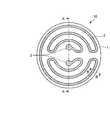
- FIG. 1 is a plan view showing an example of wiring of a heater wire of a ceramic heater according to an embodiment of the present invention.
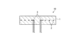
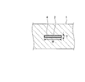
- 2 is a cross-sectional view taken along the line AA of the ceramic heater of FIG. 3 is a partially enlarged cross-sectional view taken along the line BB of the ceramic heater of FIG.
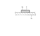
- FIG. 4 is a cross-sectional view for explaining a manufacturing process of the ceramic heater according to the embodiment of the present invention.
- FIG. 5 is a cross-sectional view illustrating a manufacturing process of the ceramic heater according to the embodiment of the present invention.
- FIG. 6 is a cross-sectional view for explaining a manufacturing process of the ceramic heater according to the embodiment of the present invention.
- FIG. 7 is a cross-sectional view illustrating a manufacturing process of the ceramic heater according to the embodiment of the present invention.
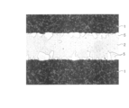
- FIG. 8 is a photograph showing a partial cross section of a ceramic heater according to a conventional example.
- FIG. 9 is a photograph showing a partial cross section of the ceramic heater according to Example 1.
- a ceramic heater 10 according to an embodiment of the present invention includes a disk-shaped heater plate 1 and a foil-shaped heater wire 2 embedded in the heater plate 1.
- FIG. 1 is a plan view showing an example of wiring of heater wires of a ceramic heater 10 according to an embodiment of the present invention.
- FIG. 2 is a cross-sectional view taken along the line AA of the ceramic heater 10 of FIG.
- FIG. 3 is a partially enlarged sectional view taken along line BB of the ceramic heater 10 of FIG.
- the heater plate 1 functions as a mounting plate for performing etching or film formation on a wafer in a semiconductor manufacturing process.
- the heater plate 1 has a disk shape of about 200 to 500 mm depending on the shape of a workpiece such as a wafer.
- As a material of the heater plate 1 aluminum nitride (AlN), silicon nitride (SiNx), aluminum oxide (Al 2 O 3 ), or the like is preferably used.
- the heater plate 1 is sintered at a temperature corresponding to the material used and the sintering aid.
- AlN aluminum nitride
- SiNx silicon nitride
- Al 2 O 3 aluminum oxide
- the heater wire 2 is embedded in the heater plate 1 in a spiral shape as shown in FIG.
- a heat-resistant metal material such as molybdenum or molybdenum alloy, tungsten or tungsten alloy, or niobium or niobium alloy is preferably used.
- the heater wire 2 has a foil shape with a thickness (T) of 25 to 200 ⁇ m and a width (W) of 1 to 10 mm.
- T thickness
- W width
- a linear or coil-shaped heater wire having a rectangular or circular cross section may be used.
- a metal carbide film 4 is formed on the surface of the heater wire 2 as shown in FIG.
- the metal carbide film 4 is formed by carbonizing a metal film 4 a (see FIG. 4) formed on the surface of the heater wire 2 by sintering the heater plate 1.
- the standard generation free energy ( ⁇ G 0 MaC ) of the metal carbide (MaC) is the standard generation free energy ( ⁇ G) of the carbide (MbC) of the metal material (Mb) of the heater wire 2. 0 MbC ) smaller material.
- the standard free energy of formation of the metal carbide that is the standard for selecting the material of the metal film 4a is the standard free energy of reaction in a predetermined temperature range. In the present embodiment, the determination is made based on the standard reaction free energy of the metal carbide in the vicinity of the sintering temperature of the heater plate 1.
- a metal film 4a selected from a material in which the standard reaction free energy of the metal carbide near the sintering temperature is smaller than the standard reaction free energy of the metal carbide of the metal material of the heater wire 2 During the sintering, the metal film 4a reacts preferentially with the carbon contained in the heater plate 1 on the order of several ppm over the material of the heater wire 2, so that the metal carbide film 4 is formed.
- carbonization of the metal that is the material of the heater wire 2 can be suppressed.
- the carbide layer of the metal material is between the heater wire 2 and the metal carbide coating 4. Since it is formed substantially uniformly, it is possible to suppress the non-uniform conductivity of the heater wire 2 wired in the heater plate 1 and to prevent the temperature distribution of the ceramic heater 10 from occurring.
- Titanium, aluminum, tantalum or zirconium is suitable as the metal film 4a, but calcium, chromium, vanadium, etc. can be used depending on the sintering temperature and the heater wire metal type.
- titanium is preferably used as the metal film 4a.
- the thickness of the metal film 4a is preferably 0.10 to 10.0 ⁇ m. This is because if the thickness is too thin, carbonization of the heater wire 2 cannot be effectively suppressed, and if the thickness is too thick, the influence due to the difference in thermal expansion during heating increases.
- Electrode terminals 3 are connected to both ends of the heater wire 2.
- the electrode terminal 3 is fixed to the heater plate 1 by brazing or the like. By applying a voltage to the electrode terminal 3 and passing a current through the heater wire 2, the heater wire 2 generates heat and heats the workpiece placed on the heater plate 1.
- 4 to 7 are cross-sectional views illustrating the manufacturing process of the ceramic heater 10 according to the embodiment of the present invention.
- a metal film 4a is formed on the surface of the heater wire 2 (see FIG. 4).
- the metal film 4a is formed on the surface of the heater wire 2 by vapor deposition or sputtering.
- the metal film 4a may be formed on the heater wire 2 by covering the heater wire 2 with two metal foils made of the material of the metal film 4a at the upper and lower sides and rolling and bonding them.
- the metal film 4a may be formed on the surface of the heater wire 2 by a method such as thermal spraying.
- the lower molded body 1a of the heater plate 1 is pressure-molded.
- the lower molded body 1a is formed by filling a predetermined amount of ceramic powder, which is a raw material of the heater plate 1, into a mold and press-molding it.
- the heater wire 2 on which the metal film 4a is formed is wired at a predetermined position.
- a predetermined amount of ceramic powder is further filled on the lower molded body 1 a with the heater wire 2, and the upper molded body 1 b is pressure-molded with a mold. To form a ceramic molded body 1c.
- the ceramic molded body 1c is sintered.
- aluminum nitride used as the ceramic material, it is heated and compressed at 1600 to 2000 ° C. and 10 to 40 MPa for several hours in a nitrogen atmosphere.
- the metal film 4 a formed on the surface of the heater wire 2 is preferentially molded to the metal material of the heater wire 2. It reacts with the carbon content in the body 1c to form a metal carbide film 4. Thereby, the electroconductive fall of the heater wire 2 can be prevented. Furthermore, even when the metal material of the heater wire 2 is carbonized by forming the metal carbide film 4, the carbonization of the metal material is stabilized, and the heater wire 2 wired in the heater plate is stabilized. Conductivity non-uniformity can be suppressed.
- the heater plate 1 After sintering, the heater plate 1 is cut to form electrode terminals 3 for supplying electric power from the outside.
- the method for manufacturing a ceramic sintered body and the ceramic sintered body of the present invention are ceramic products in which a conductive metal is embedded, for example, a stage having an electrostatic chuck function. It can also be used for ceramic stages and the like incorporating a high-frequency electrode such as a plasma etching apparatus or a plasma CVD apparatus.
- Aluminum nitride is used as the material of the heater plate 1.
- a heater wire 2 having a size of 2 mm ⁇ 6700 mm ⁇ 75 ⁇ m was formed from a pure molybdenum metal foil, and a metal film 4 a made of titanium having a thickness of 1 ⁇ m was formed on the surface of the heater wire 2 by sputtering.
- the heater wire 2 on which the metal film 4a is formed is wired at a predetermined position in the heater plate 1, press-molded, and sintered (sintering temperature 1800 ° C., pressure 20 MPa, 6 hours). Manufactured.
- FIG. 8 is a photograph showing a partial cross section of the ceramic heater according to Conventional Example 1.
- FIG. 9 is a photograph showing a partial cross section of the ceramic heater 10 according to the first example.
- the heater wire 2 having a size of 2 mm ⁇ 6700 mm ⁇ 75 ⁇ m is formed from a metal foil of aluminum nitride and pure molybdenum as the material of the heater plate 1, and the heater wire 2 is wired at a predetermined position in the heater plate 1.
- the titanium metal film 4a is formed on the surface of the molybdenum heater wire 2 by pressure molding and sintering (sintering temperature 1800 ° C., pressure 20 MPa, 6 hours). The only difference is that it is not formed.
- Table 1 shows the electrical resistance values of the heater wires 2 of Example 1 and Conventional Example 1.
- Reference Example 1 in Table 1 is an electrical resistance value of the heater wire 2 measured before sintering the ceramic heater of Example 1.
- the electrical resistance value which was 2.1 ⁇ before sintering, increased to 4.0 ⁇ (90% increase) after sintering, whereas in Example 1, after sintering, It can be seen that the increase is 2.9 ⁇ (38% increase), which is greatly suppressed.
- the metal film 4a is formed on the surface of the heater wire 2 made of molybdenum by titanium having a standard free energy of formation of metal carbide near the sintering temperature (1800 ° C.) of the ceramic heater, which is smaller than molybdenum carbide. An increase in the electric resistance value of the ceramic heater 10 formed and sintered can be significantly suppressed.
- the method for manufacturing a ceramic sintered body, the ceramic sintered body, and the ceramic heater according to the present invention can be used in a semiconductor manufacturing apparatus, and is particularly suitable for manufacturing a high-quality wafer.
- Heater Plate 1 Heater Plate 2 Heater Wire 3 Electrode Terminal 4a Metal Film 4 Metal Carbide Film 5 Molybdenum Carbide 10 Ceramic Heater
Landscapes
- Chemical & Material Sciences (AREA)
- Engineering & Computer Science (AREA)
- Ceramic Engineering (AREA)
- Materials Engineering (AREA)
- Organic Chemistry (AREA)
- Structural Engineering (AREA)
- Manufacturing & Machinery (AREA)
- Inorganic Chemistry (AREA)
- Chemical Kinetics & Catalysis (AREA)
- Mechanical Engineering (AREA)
- Metallurgy (AREA)
- Resistance Heating (AREA)
- Ceramic Products (AREA)
- Compositions Of Oxide Ceramics (AREA)
- Other Surface Treatments For Metallic Materials (AREA)
Abstract
Description

2 ヒータ線
3 電極端子
4a 金属皮膜
4 金属炭化物皮膜
5 炭化モリブデン
10 セラミックスヒータ
Claims (13)
- 耐熱性金属材料の表面に、金属炭化物の標準生成自由エネルギーが該耐熱性金属材料より小さい金属材料からなる金属皮膜を形成する皮膜形成ステップと、
前記皮膜形成ステップで皮膜を形成した前記耐熱性金属材料を、セラミックス基体の原材料である粉体中の所定の位置に配設し、加圧成型してセラミックス成型体を成型する成型ステップと、
前記成型ステップで成型したセラミックス成型体を焼結してセラミックス焼結体を生成する焼結ステップと、
を含むことを特徴とするセラミックス焼結体の製造方法。 - 前記耐熱性金属材料は、モリブデンもしくはモリブデン合金、タングステンもしくはタングステン合金、ニオブもしくはニオブ合金から選択される高融点低熱膨張金属であることを特徴とする請求項1に記載のセラミックス焼結体の製造方法。
- 前記金属皮膜は、チタン、アルミニウム、タンタルまたはジルコニウムから形成されることを特徴とする請求項1に記載のセラミックス焼結体の製造方法。
- 前記セラミックス基体は、窒化アルミニウム、窒化珪素または酸化アルミニウムであることを特徴とする請求項1に記載のセラミックス焼結体の製造方法。
- 前記セラミックス焼結体の焼結温度は、1300~2000℃であることを特徴とする請求項1に記載のセラミックス焼結体の製造方法。
- 前記金属皮膜の厚さは0.10~10.0μmであることを特徴とする請求項1~5のいずれか一つに記載のセラミックス焼結体の製造方法。
- 耐熱性金属材料と、
前記耐熱性金属材料の表面に形成され、金属炭化物の標準生成自由エネルギーが前記耐熱性金属材料よりも小さい金属材料からなる金属皮膜と、
前記金属皮膜が形成された耐熱性金属材料をセラミックス基体の原材料である粉体中の所定の位置に配設し、加圧成型されたセラミックス成型体と、
を備えるプレセラミックスを焼結して形成され、前記焼結時に前記金属皮膜が炭化されて金属炭化物皮膜が形成されることを特徴とするセラミックス焼結体。 - 前記耐熱性金属材料は、モリブデンもしくはモリブデン合金、タングステンもしくはタングステン合金、ニオブもしくはニオブ合金から選択される高融点低熱膨張金属であることを特徴とする請求項7に記載のセラミックス焼結体。
- 前記金属皮膜は、チタン、アルミニウム、タンタルまたはジルコニウムから形成されることを特徴とする請求項7に記載のセラミックス焼結体。
- 前記セラミックス基体は、窒化アルミニウム、窒化珪素または酸化アルミニウムであることを特徴とする請求項7に記載のセラミックス焼結体。
- 前記セラミックス焼結体の焼結温度は、1300~2000℃であることを特徴とする請求項7に記載のセラミックス焼結体。
- 前記金属皮膜の厚さは0.10~10.0μmであることを特徴とする請求項7~11のいずれか一つに記載のセラミックス焼結体。
- 請求項7~12のいずれか一つに記載のセラミックス焼結体を備えることを特徴とするセラミックスヒータ。
Priority Applications (3)
| Application Number | Priority Date | Filing Date | Title |
|---|---|---|---|
| KR1020137010379A KR101462123B1 (ko) | 2010-10-29 | 2011-10-24 | 세라믹스 소결체의 제조방법, 세라믹스 소결체 및 세라믹스 히터 |
| US13/879,882 US10462850B2 (en) | 2010-10-29 | 2011-10-24 | Method of manufacturing ceramic sintered body, ceramic sintered body, and ceramic heater |
| CN201180051086.5A CN103180268B (zh) | 2010-10-29 | 2011-10-24 | 陶瓷烧结体的制造方法、陶瓷烧结体及陶瓷加热器 |
Applications Claiming Priority (2)
| Application Number | Priority Date | Filing Date | Title |
|---|---|---|---|
| JP2010244498A JP5341049B2 (ja) | 2010-10-29 | 2010-10-29 | セラミックス焼結体の製造方法、セラミックス焼結体およびセラミックスヒータ |
| JP2010-244498 | 2010-10-29 |
Publications (1)
| Publication Number | Publication Date |
|---|---|
| WO2012057091A1 true WO2012057091A1 (ja) | 2012-05-03 |
Family
ID=45993799
Family Applications (1)
| Application Number | Title | Priority Date | Filing Date |
|---|---|---|---|
| PCT/JP2011/074458 Ceased WO2012057091A1 (ja) | 2010-10-29 | 2011-10-24 | セラミックス焼結体の製造方法、セラミックス焼結体およびセラミックスヒータ |
Country Status (6)
| Country | Link |
|---|---|
| US (1) | US10462850B2 (ja) |
| JP (1) | JP5341049B2 (ja) |
| KR (1) | KR101462123B1 (ja) |
| CN (1) | CN103180268B (ja) |
| TW (1) | TWI466847B (ja) |
| WO (1) | WO2012057091A1 (ja) |
Cited By (3)
| Publication number | Priority date | Publication date | Assignee | Title |
|---|---|---|---|---|
| WO2020105521A1 (ja) * | 2018-11-19 | 2020-05-28 | 日本特殊陶業株式会社 | 保持装置および保持装置の製造方法 |
| TWI697253B (zh) * | 2018-05-22 | 2020-06-21 | 美商瓦特洛威電子製造公司 | 一體式加熱器及製造方法 |
| US11083050B2 (en) | 2017-11-21 | 2021-08-03 | Watlow Electric Manufacturing Company | Integrated heater and method of manufacture |
Families Citing this family (10)
| Publication number | Priority date | Publication date | Assignee | Title |
|---|---|---|---|---|
| JP6049509B2 (ja) * | 2012-03-28 | 2016-12-21 | 日本碍子株式会社 | セラミックヒーター、ヒーター電極及びセラミックヒーターの製法 |
| CN103596304B (zh) * | 2013-11-07 | 2015-10-28 | 上海大学 | 一种嵌入式自测温微热台及其制备方法 |
| DE102016111234B4 (de) * | 2016-06-20 | 2018-01-25 | Heraeus Noblelight Gmbh | Vorrichtung für die thermische Behandlung eines Substrats sowie Trägerhorde und Substrat-Trägerelement dafür |
| US10674566B2 (en) * | 2017-03-02 | 2020-06-02 | Coorstek Kk | Planar heater |
| KR102272523B1 (ko) * | 2017-06-01 | 2021-07-05 | 주식회사 미코세라믹스 | 세라믹 히터의 제조 방법 |
| JP6461300B1 (ja) | 2017-12-28 | 2019-01-30 | 株式会社Maruwa | セラミック装置 |
| KR102582111B1 (ko) * | 2018-02-28 | 2023-09-25 | 주식회사 미코세라믹스 | 세라믹 히터 및 그 제조 방법 |
| CN113170536B (zh) * | 2019-01-25 | 2023-06-09 | 日本碍子株式会社 | 陶瓷加热器及其制法 |
| CN115917722A (zh) * | 2020-09-29 | 2023-04-04 | 朗姆研究公司 | 用于嵌入陶瓷件的加热器的涂层导体 |
| KR102855587B1 (ko) * | 2022-02-08 | 2025-09-05 | 주식회사 아모센스 | 세라믹 히터 플레이트 제조방법, 이를 통해 제조된 세라믹 히터 플레이트 및 이를 포함하는 반도체 유지장치 |
Citations (6)
| Publication number | Priority date | Publication date | Assignee | Title |
|---|---|---|---|---|
| JPS61179084A (ja) * | 1985-01-31 | 1986-08-11 | 京セラ株式会社 | セラミツクヒ−タおよびその製法 |
| JPH03226986A (ja) * | 1990-01-31 | 1991-10-07 | Toshiba Corp | セラミックス配線基板の製造方法およびセラミックス発熱体 |
| JPH07135068A (ja) * | 1993-11-12 | 1995-05-23 | Ngk Insulators Ltd | セラミックスヒーター |
| JP2001244321A (ja) * | 2000-03-02 | 2001-09-07 | Ngk Insulators Ltd | 静電チャックおよびその製造方法 |
| JP2003288975A (ja) * | 2002-03-27 | 2003-10-10 | Ngk Insulators Ltd | セラミックヒーター、セラミックヒーターの製造方法、および金属部材の埋設品 |
| JP2009295960A (ja) * | 2008-05-02 | 2009-12-17 | Ngk Insulators Ltd | セラミックスヒータ及びその製造方法 |
Family Cites Families (18)
| Publication number | Priority date | Publication date | Assignee | Title |
|---|---|---|---|---|
| US5034352A (en) * | 1985-06-25 | 1991-07-23 | Lifecore Biomedical, Inc. | Calcium phosphate materials |
| US4943468A (en) * | 1988-10-31 | 1990-07-24 | Texas Instruments Incorporated | Ceramic based substrate for electronic circuit system modules |
| US5615078A (en) * | 1994-12-16 | 1997-03-25 | Aerovox Incorporated | Metallized film for electrical capacitors having a semiconductive layer extending entirely across the unmetallized margin |
| US5851599A (en) * | 1995-09-28 | 1998-12-22 | Sumitomo Electric Industries Co., Ltd. | Battery electrode substrate and process for producing the same |
| US6071644A (en) * | 1996-09-30 | 2000-06-06 | Sanyo Electric Co., Ltd. | Metal hydride storage cell and method of producing hydrogen absorbing alloy electrode |
| JP3381909B2 (ja) * | 1999-08-10 | 2003-03-04 | イビデン株式会社 | 半導体製造・検査装置用セラミックヒータ |
| JP2001244231A (ja) | 2000-02-25 | 2001-09-07 | Ses Co Ltd | 横軸式基板回転乾燥装置 |
| US6555031B2 (en) * | 2000-06-19 | 2003-04-29 | Corning Incorporated | Process for producing silicon carbide bodies |
| US6815646B2 (en) | 2000-07-25 | 2004-11-09 | Ibiden Co., Ltd. | Ceramic substrate for semiconductor manufacture/inspection apparatus, ceramic heater, electrostatic clampless holder, and substrate for wafer prober |
| CN1460094A (zh) * | 2001-04-12 | 2003-12-03 | 揖斐电株式会社 | 陶瓷接合体、其制造方法以及半导体晶片用陶瓷结构体 |
| EP1406472A1 (en) * | 2001-07-09 | 2004-04-07 | Ibiden Co., Ltd. | Ceramic heater and ceramic joined article |
| JP4737492B2 (ja) * | 2001-09-04 | 2011-08-03 | 独立行政法人理化学研究所 | メタルレスボンド砥石とそれによる電解ドレッシング研削方法及び装置 |
| KR100790657B1 (ko) * | 2003-05-29 | 2008-01-02 | 미쓰비시덴키 가부시키가이샤 | 방전 표면 처리용 전극 및 방전 표면 처리 방법 및 방전표면 처리 장치 |
| US20050014851A1 (en) * | 2003-07-18 | 2005-01-20 | Eastman Kodak Company | Colloidal core-shell assemblies and methods of preparation |
| EP2154520B1 (en) * | 2007-05-08 | 2015-12-09 | Ideal Star Inc. | Gas sensor, gas measuring system using the gas sensor, and gas detection method |
| KR20090026568A (ko) * | 2007-09-10 | 2009-03-13 | 삼성전자주식회사 | 그라펜 시트 및 그의 제조방법 |
| JP5019545B2 (ja) * | 2008-10-24 | 2012-09-05 | 日本特殊陶業株式会社 | セラミック接合体、セラミックヒータおよびガスセンサ |
| JP5358543B2 (ja) * | 2009-09-17 | 2013-12-04 | 日本碍子株式会社 | セラミックスヒーター及びその製造方法 |
-
2010
- 2010-10-29 JP JP2010244498A patent/JP5341049B2/ja active Active
-
2011
- 2011-10-24 CN CN201180051086.5A patent/CN103180268B/zh active Active
- 2011-10-24 WO PCT/JP2011/074458 patent/WO2012057091A1/ja not_active Ceased
- 2011-10-24 KR KR1020137010379A patent/KR101462123B1/ko active Active
- 2011-10-24 US US13/879,882 patent/US10462850B2/en active Active
- 2011-10-28 TW TW100139299A patent/TWI466847B/zh active
Patent Citations (6)
| Publication number | Priority date | Publication date | Assignee | Title |
|---|---|---|---|---|
| JPS61179084A (ja) * | 1985-01-31 | 1986-08-11 | 京セラ株式会社 | セラミツクヒ−タおよびその製法 |
| JPH03226986A (ja) * | 1990-01-31 | 1991-10-07 | Toshiba Corp | セラミックス配線基板の製造方法およびセラミックス発熱体 |
| JPH07135068A (ja) * | 1993-11-12 | 1995-05-23 | Ngk Insulators Ltd | セラミックスヒーター |
| JP2001244321A (ja) * | 2000-03-02 | 2001-09-07 | Ngk Insulators Ltd | 静電チャックおよびその製造方法 |
| JP2003288975A (ja) * | 2002-03-27 | 2003-10-10 | Ngk Insulators Ltd | セラミックヒーター、セラミックヒーターの製造方法、および金属部材の埋設品 |
| JP2009295960A (ja) * | 2008-05-02 | 2009-12-17 | Ngk Insulators Ltd | セラミックスヒータ及びその製造方法 |
Cited By (11)
| Publication number | Priority date | Publication date | Assignee | Title |
|---|---|---|---|---|
| US11083050B2 (en) | 2017-11-21 | 2021-08-03 | Watlow Electric Manufacturing Company | Integrated heater and method of manufacture |
| TWI697253B (zh) * | 2018-05-22 | 2020-06-21 | 美商瓦特洛威電子製造公司 | 一體式加熱器及製造方法 |
| TWI724951B (zh) * | 2018-05-22 | 2021-04-11 | 美商瓦特洛威電子製造公司 | 一體式加熱器及製造方法 |
| WO2020105521A1 (ja) * | 2018-11-19 | 2020-05-28 | 日本特殊陶業株式会社 | 保持装置および保持装置の製造方法 |
| WO2020105522A1 (ja) * | 2018-11-19 | 2020-05-28 | 日本特殊陶業株式会社 | 保持装置および保持装置の製造方法 |
| KR20200085306A (ko) * | 2018-11-19 | 2020-07-14 | 니뽄 도쿠슈 도교 가부시키가이샤 | 유지 장치 및 유지 장치의 제조 방법 |
| CN111527790A (zh) * | 2018-11-19 | 2020-08-11 | 日本特殊陶业株式会社 | 保持装置及保持装置的制造方法 |
| JPWO2020105522A1 (ja) * | 2018-11-19 | 2021-02-15 | 日本特殊陶業株式会社 | 保持装置および保持装置の製造方法 |
| JPWO2020105521A1 (ja) * | 2018-11-19 | 2021-02-15 | 日本特殊陶業株式会社 | 保持装置および保持装置の製造方法 |
| KR102328766B1 (ko) | 2018-11-19 | 2021-11-18 | 니뽄 도쿠슈 도교 가부시키가이샤 | 유지 장치 및 유지 장치의 제조 방법 |
| CN111527790B (zh) * | 2018-11-19 | 2022-05-06 | 日本特殊陶业株式会社 | 保持装置及保持装置的制造方法 |
Also Published As
| Publication number | Publication date |
|---|---|
| KR101462123B1 (ko) | 2014-11-17 |
| US20130200067A1 (en) | 2013-08-08 |
| TWI466847B (zh) | 2015-01-01 |
| TW201223915A (en) | 2012-06-16 |
| CN103180268B (zh) | 2014-08-27 |
| CN103180268A (zh) | 2013-06-26 |
| JP2012096948A (ja) | 2012-05-24 |
| JP5341049B2 (ja) | 2013-11-13 |
| US10462850B2 (en) | 2019-10-29 |
| KR20130061183A (ko) | 2013-06-10 |
Similar Documents
| Publication | Publication Date | Title |
|---|---|---|
| JP5341049B2 (ja) | セラミックス焼結体の製造方法、セラミックス焼結体およびセラミックスヒータ | |
| JP4467453B2 (ja) | セラミックス部材及びその製造方法 | |
| JP4476701B2 (ja) | 電極内蔵焼結体の製造方法 | |
| JP5117146B2 (ja) | 加熱装置 | |
| JP4495539B2 (ja) | 電極内蔵発熱体の製造方法 | |
| US20040188413A1 (en) | Ceramic Susceptor and Semiconductor or Liquid-Crystal Manufacturing Apparatus in Which the Susceptor Is Installed | |
| JP7465771B2 (ja) | 複合焼結体、半導体製造装置部材および複合焼結体の製造方法 | |
| KR20200131884A (ko) | 복합 소결체, 반도체 제조 장치 부재 및 복합 소결체의 제조 방법 | |
| JP5740637B2 (ja) | セラミックス接合体及びその製造方法 | |
| JP4531004B2 (ja) | 加熱装置 | |
| TWI728829B (zh) | 晶圓載置台及其製造方法 | |
| KR100706064B1 (ko) | 세라믹스 부재 및 그 제조 방법 | |
| JP5320104B2 (ja) | セラミックスヒータ及びその製造方法 | |
| JP4566213B2 (ja) | 加熱装置およびその製造方法 | |
| JP4482535B2 (ja) | 加熱装置 | |
| KR102737267B1 (ko) | 복합 소결체 및 복합 소결체의 제조 방법 | |
| JP7628358B2 (ja) | 電極埋設部材、その製造方法、および基板保持部材 | |
| JP2004289137A (ja) | 半導体製造装置用ウェハ保持体及びそれを搭載した半導体製造装置 | |
| JP4199604B2 (ja) | 窒化アルミニウムのセラミックスヒータ | |
| JP7628754B2 (ja) | 電極埋設部材、その製造方法、および基板保持部材 | |
| JP4789416B2 (ja) | セラミック抵抗体及びその製造方法並びに静電チャック | |
| JP2024021400A (ja) | セラミックスヒーター、およびその製造方法 | |
| JP2006164595A (ja) | 薄膜発熱体およびその製造方法 | |
| US20040182322A1 (en) | Wafer holder for semiconductor manufacturing device and semiconductor manufacturing device in which it is installed |
Legal Events
| Date | Code | Title | Description |
|---|---|---|---|
| 121 | Ep: the epo has been informed by wipo that ep was designated in this application |
Ref document number: 11836224 Country of ref document: EP Kind code of ref document: A1 |
|
| WWE | Wipo information: entry into national phase |
Ref document number: 13879882 Country of ref document: US |
|
| ENP | Entry into the national phase |
Ref document number: 20137010379 Country of ref document: KR Kind code of ref document: A |
|
| NENP | Non-entry into the national phase |
Ref country code: DE |
|
| 122 | Ep: pct application non-entry in european phase |
Ref document number: 11836224 Country of ref document: EP Kind code of ref document: A1 |