WO2012056876A1 - セラミックス材料、半導体製造装置用部材、スパッタリングターゲット部材及びセラミックス材料の製造方法 - Google Patents
セラミックス材料、半導体製造装置用部材、スパッタリングターゲット部材及びセラミックス材料の製造方法 Download PDFInfo
- Publication number
- WO2012056876A1 WO2012056876A1 PCT/JP2011/073330 JP2011073330W WO2012056876A1 WO 2012056876 A1 WO2012056876 A1 WO 2012056876A1 JP 2011073330 W JP2011073330 W JP 2011073330W WO 2012056876 A1 WO2012056876 A1 WO 2012056876A1
- Authority
- WO
- WIPO (PCT)
- Prior art keywords
- ceramic material
- plane
- mgo
- solid solution
- peak
- Prior art date
- Legal status (The legal status is an assumption and is not a legal conclusion. Google has not performed a legal analysis and makes no representation as to the accuracy of the status listed.)
- Ceased
Links
Images

Classifications
-
- C—CHEMISTRY; METALLURGY
- C04—CEMENTS; CONCRETE; ARTIFICIAL STONE; CERAMICS; REFRACTORIES
- C04B—LIME, MAGNESIA; SLAG; CEMENTS; COMPOSITIONS THEREOF, e.g. MORTARS, CONCRETE OR LIKE BUILDING MATERIALS; ARTIFICIAL STONE; CERAMICS; REFRACTORIES; TREATMENT OF NATURAL STONE
- C04B35/00—Shaped ceramic products characterised by their composition; Ceramics compositions; Processing powders of inorganic compounds preparatory to the manufacturing of ceramic products
- C04B35/515—Shaped ceramic products characterised by their composition; Ceramics compositions; Processing powders of inorganic compounds preparatory to the manufacturing of ceramic products based on non-oxide ceramics
- C04B35/58—Shaped ceramic products characterised by their composition; Ceramics compositions; Processing powders of inorganic compounds preparatory to the manufacturing of ceramic products based on non-oxide ceramics based on borides, nitrides, i.e. nitrides, oxynitrides, carbonitrides or oxycarbonitrides or silicides
- C04B35/581—Shaped ceramic products characterised by their composition; Ceramics compositions; Processing powders of inorganic compounds preparatory to the manufacturing of ceramic products based on non-oxide ceramics based on borides, nitrides, i.e. nitrides, oxynitrides, carbonitrides or oxycarbonitrides or silicides based on aluminium nitride
-
- C—CHEMISTRY; METALLURGY
- C04—CEMENTS; CONCRETE; ARTIFICIAL STONE; CERAMICS; REFRACTORIES
- C04B—LIME, MAGNESIA; SLAG; CEMENTS; COMPOSITIONS THEREOF, e.g. MORTARS, CONCRETE OR LIKE BUILDING MATERIALS; ARTIFICIAL STONE; CERAMICS; REFRACTORIES; TREATMENT OF NATURAL STONE
- C04B35/00—Shaped ceramic products characterised by their composition; Ceramics compositions; Processing powders of inorganic compounds preparatory to the manufacturing of ceramic products
- C04B35/01—Shaped ceramic products characterised by their composition; Ceramics compositions; Processing powders of inorganic compounds preparatory to the manufacturing of ceramic products based on oxide ceramics
- C04B35/03—Shaped ceramic products characterised by their composition; Ceramics compositions; Processing powders of inorganic compounds preparatory to the manufacturing of ceramic products based on oxide ceramics based on magnesium oxide, calcium oxide or oxide mixtures derived from dolomite
- C04B35/04—Shaped ceramic products characterised by their composition; Ceramics compositions; Processing powders of inorganic compounds preparatory to the manufacturing of ceramic products based on oxide ceramics based on magnesium oxide, calcium oxide or oxide mixtures derived from dolomite based on magnesium oxide
-
- C—CHEMISTRY; METALLURGY
- C04—CEMENTS; CONCRETE; ARTIFICIAL STONE; CERAMICS; REFRACTORIES
- C04B—LIME, MAGNESIA; SLAG; CEMENTS; COMPOSITIONS THEREOF, e.g. MORTARS, CONCRETE OR LIKE BUILDING MATERIALS; ARTIFICIAL STONE; CERAMICS; REFRACTORIES; TREATMENT OF NATURAL STONE
- C04B35/00—Shaped ceramic products characterised by their composition; Ceramics compositions; Processing powders of inorganic compounds preparatory to the manufacturing of ceramic products
- C04B35/515—Shaped ceramic products characterised by their composition; Ceramics compositions; Processing powders of inorganic compounds preparatory to the manufacturing of ceramic products based on non-oxide ceramics
- C04B35/58—Shaped ceramic products characterised by their composition; Ceramics compositions; Processing powders of inorganic compounds preparatory to the manufacturing of ceramic products based on non-oxide ceramics based on borides, nitrides, i.e. nitrides, oxynitrides, carbonitrides or oxycarbonitrides or silicides
-
- C—CHEMISTRY; METALLURGY
- C04—CEMENTS; CONCRETE; ARTIFICIAL STONE; CERAMICS; REFRACTORIES
- C04B—LIME, MAGNESIA; SLAG; CEMENTS; COMPOSITIONS THEREOF, e.g. MORTARS, CONCRETE OR LIKE BUILDING MATERIALS; ARTIFICIAL STONE; CERAMICS; REFRACTORIES; TREATMENT OF NATURAL STONE
- C04B35/00—Shaped ceramic products characterised by their composition; Ceramics compositions; Processing powders of inorganic compounds preparatory to the manufacturing of ceramic products
- C04B35/622—Forming processes; Processing powders of inorganic compounds preparatory to the manufacturing of ceramic products
- C04B35/626—Preparing or treating the powders individually or as batches ; preparing or treating macroscopic reinforcing agents for ceramic products, e.g. fibres; mechanical aspects section B
- C04B35/62605—Treating the starting powders individually or as mixtures
- C04B35/6261—Milling
-
- C—CHEMISTRY; METALLURGY
- C04—CEMENTS; CONCRETE; ARTIFICIAL STONE; CERAMICS; REFRACTORIES
- C04B—LIME, MAGNESIA; SLAG; CEMENTS; COMPOSITIONS THEREOF, e.g. MORTARS, CONCRETE OR LIKE BUILDING MATERIALS; ARTIFICIAL STONE; CERAMICS; REFRACTORIES; TREATMENT OF NATURAL STONE
- C04B35/00—Shaped ceramic products characterised by their composition; Ceramics compositions; Processing powders of inorganic compounds preparatory to the manufacturing of ceramic products
- C04B35/622—Forming processes; Processing powders of inorganic compounds preparatory to the manufacturing of ceramic products
- C04B35/626—Preparing or treating the powders individually or as batches ; preparing or treating macroscopic reinforcing agents for ceramic products, e.g. fibres; mechanical aspects section B
- C04B35/62605—Treating the starting powders individually or as mixtures
- C04B35/62645—Thermal treatment of powders or mixtures thereof other than sintering
- C04B35/62655—Drying, e.g. freeze-drying, spray-drying, microwave or supercritical drying
-
- C—CHEMISTRY; METALLURGY
- C04—CEMENTS; CONCRETE; ARTIFICIAL STONE; CERAMICS; REFRACTORIES
- C04B—LIME, MAGNESIA; SLAG; CEMENTS; COMPOSITIONS THEREOF, e.g. MORTARS, CONCRETE OR LIKE BUILDING MATERIALS; ARTIFICIAL STONE; CERAMICS; REFRACTORIES; TREATMENT OF NATURAL STONE
- C04B35/00—Shaped ceramic products characterised by their composition; Ceramics compositions; Processing powders of inorganic compounds preparatory to the manufacturing of ceramic products
- C04B35/622—Forming processes; Processing powders of inorganic compounds preparatory to the manufacturing of ceramic products
- C04B35/64—Burning or sintering processes
- C04B35/645—Pressure sintering
-
- C—CHEMISTRY; METALLURGY
- C23—COATING METALLIC MATERIAL; COATING MATERIAL WITH METALLIC MATERIAL; CHEMICAL SURFACE TREATMENT; DIFFUSION TREATMENT OF METALLIC MATERIAL; COATING BY VACUUM EVAPORATION, BY SPUTTERING, BY ION IMPLANTATION OR BY CHEMICAL VAPOUR DEPOSITION, IN GENERAL; INHIBITING CORROSION OF METALLIC MATERIAL OR INCRUSTATION IN GENERAL
- C23C—COATING METALLIC MATERIAL; COATING MATERIAL WITH METALLIC MATERIAL; SURFACE TREATMENT OF METALLIC MATERIAL BY DIFFUSION INTO THE SURFACE, BY CHEMICAL CONVERSION OR SUBSTITUTION; COATING BY VACUUM EVAPORATION, BY SPUTTERING, BY ION IMPLANTATION OR BY CHEMICAL VAPOUR DEPOSITION, IN GENERAL
- C23C14/00—Coating by vacuum evaporation, by sputtering or by ion implantation of the coating forming material
- C23C14/22—Coating by vacuum evaporation, by sputtering or by ion implantation of the coating forming material characterised by the process of coating
- C23C14/34—Sputtering
- C23C14/3407—Cathode assembly for sputtering apparatus, e.g. Target
- C23C14/3414—Metallurgical or chemical aspects of target preparation, e.g. casting, powder metallurgy
-
- H—ELECTRICITY
- H10—SEMICONDUCTOR DEVICES; ELECTRIC SOLID-STATE DEVICES NOT OTHERWISE PROVIDED FOR
- H10P—GENERIC PROCESSES OR APPARATUS FOR THE MANUFACTURE OR TREATMENT OF DEVICES COVERED BY CLASS H10
- H10P14/00—Formation of materials, e.g. in the shape of layers or pillars
- H10P14/60—Formation of materials, e.g. in the shape of layers or pillars of insulating materials
-
- H—ELECTRICITY
- H10—SEMICONDUCTOR DEVICES; ELECTRIC SOLID-STATE DEVICES NOT OTHERWISE PROVIDED FOR
- H10P—GENERIC PROCESSES OR APPARATUS FOR THE MANUFACTURE OR TREATMENT OF DEVICES COVERED BY CLASS H10
- H10P50/00—Etching of wafers, substrates or parts of devices
- H10P50/20—Dry etching; Plasma etching; Reactive-ion etching
- H10P50/24—Dry etching; Plasma etching; Reactive-ion etching of semiconductor materials
- H10P50/242—Dry etching; Plasma etching; Reactive-ion etching of semiconductor materials of Group IV materials
-
- H—ELECTRICITY
- H10—SEMICONDUCTOR DEVICES; ELECTRIC SOLID-STATE DEVICES NOT OTHERWISE PROVIDED FOR
- H10P—GENERIC PROCESSES OR APPARATUS FOR THE MANUFACTURE OR TREATMENT OF DEVICES COVERED BY CLASS H10
- H10P72/00—Handling or holding of wafers, substrates or devices during manufacture or treatment thereof
- H10P72/70—Handling or holding of wafers, substrates or devices during manufacture or treatment thereof for supporting or gripping
- H10P72/72—Handling or holding of wafers, substrates or devices during manufacture or treatment thereof for supporting or gripping using electrostatic chucks
- H10P72/722—Details of electrostatic chucks
-
- C—CHEMISTRY; METALLURGY
- C04—CEMENTS; CONCRETE; ARTIFICIAL STONE; CERAMICS; REFRACTORIES
- C04B—LIME, MAGNESIA; SLAG; CEMENTS; COMPOSITIONS THEREOF, e.g. MORTARS, CONCRETE OR LIKE BUILDING MATERIALS; ARTIFICIAL STONE; CERAMICS; REFRACTORIES; TREATMENT OF NATURAL STONE
- C04B2235/00—Aspects relating to ceramic starting mixtures or sintered ceramic products
- C04B2235/02—Composition of constituents of the starting material or of secondary phases of the final product
- C04B2235/30—Constituents and secondary phases not being of a fibrous nature
- C04B2235/32—Metal oxides, mixed metal oxides, or oxide-forming salts thereof, e.g. carbonates, nitrates, (oxy)hydroxides, chlorides
- C04B2235/3205—Alkaline earth oxides or oxide forming salts thereof, e.g. beryllium oxide
- C04B2235/3206—Magnesium oxides or oxide-forming salts thereof
-
- C—CHEMISTRY; METALLURGY
- C04—CEMENTS; CONCRETE; ARTIFICIAL STONE; CERAMICS; REFRACTORIES
- C04B—LIME, MAGNESIA; SLAG; CEMENTS; COMPOSITIONS THEREOF, e.g. MORTARS, CONCRETE OR LIKE BUILDING MATERIALS; ARTIFICIAL STONE; CERAMICS; REFRACTORIES; TREATMENT OF NATURAL STONE
- C04B2235/00—Aspects relating to ceramic starting mixtures or sintered ceramic products
- C04B2235/02—Composition of constituents of the starting material or of secondary phases of the final product
- C04B2235/30—Constituents and secondary phases not being of a fibrous nature
- C04B2235/32—Metal oxides, mixed metal oxides, or oxide-forming salts thereof, e.g. carbonates, nitrates, (oxy)hydroxides, chlorides
- C04B2235/3217—Aluminum oxide or oxide forming salts thereof, e.g. bauxite, alpha-alumina
- C04B2235/3222—Aluminates other than alumino-silicates, e.g. spinel (MgAl2O4)
-
- C—CHEMISTRY; METALLURGY
- C04—CEMENTS; CONCRETE; ARTIFICIAL STONE; CERAMICS; REFRACTORIES
- C04B—LIME, MAGNESIA; SLAG; CEMENTS; COMPOSITIONS THEREOF, e.g. MORTARS, CONCRETE OR LIKE BUILDING MATERIALS; ARTIFICIAL STONE; CERAMICS; REFRACTORIES; TREATMENT OF NATURAL STONE
- C04B2235/00—Aspects relating to ceramic starting mixtures or sintered ceramic products
- C04B2235/02—Composition of constituents of the starting material or of secondary phases of the final product
- C04B2235/30—Constituents and secondary phases not being of a fibrous nature
- C04B2235/38—Non-oxide ceramic constituents or additives
- C04B2235/3852—Nitrides, e.g. oxynitrides, carbonitrides, oxycarbonitrides, lithium nitride, magnesium nitride
- C04B2235/3865—Aluminium nitrides
- C04B2235/3869—Aluminium oxynitrides, e.g. AlON, sialon
-
- C—CHEMISTRY; METALLURGY
- C04—CEMENTS; CONCRETE; ARTIFICIAL STONE; CERAMICS; REFRACTORIES
- C04B—LIME, MAGNESIA; SLAG; CEMENTS; COMPOSITIONS THEREOF, e.g. MORTARS, CONCRETE OR LIKE BUILDING MATERIALS; ARTIFICIAL STONE; CERAMICS; REFRACTORIES; TREATMENT OF NATURAL STONE
- C04B2235/00—Aspects relating to ceramic starting mixtures or sintered ceramic products
- C04B2235/02—Composition of constituents of the starting material or of secondary phases of the final product
- C04B2235/50—Constituents or additives of the starting mixture chosen for their shape or used because of their shape or their physical appearance
- C04B2235/54—Particle size related information
- C04B2235/5418—Particle size related information expressed by the size of the particles or aggregates thereof
- C04B2235/5445—Particle size related information expressed by the size of the particles or aggregates thereof submicron sized, i.e. from 0,1 to 1 micron
-
- C—CHEMISTRY; METALLURGY
- C04—CEMENTS; CONCRETE; ARTIFICIAL STONE; CERAMICS; REFRACTORIES
- C04B—LIME, MAGNESIA; SLAG; CEMENTS; COMPOSITIONS THEREOF, e.g. MORTARS, CONCRETE OR LIKE BUILDING MATERIALS; ARTIFICIAL STONE; CERAMICS; REFRACTORIES; TREATMENT OF NATURAL STONE
- C04B2235/00—Aspects relating to ceramic starting mixtures or sintered ceramic products
- C04B2235/70—Aspects relating to sintered or melt-casted ceramic products
- C04B2235/74—Physical characteristics
- C04B2235/76—Crystal structural characteristics, e.g. symmetry
- C04B2235/762—Cubic symmetry, e.g. beta-SiC
-
- C—CHEMISTRY; METALLURGY
- C04—CEMENTS; CONCRETE; ARTIFICIAL STONE; CERAMICS; REFRACTORIES
- C04B—LIME, MAGNESIA; SLAG; CEMENTS; COMPOSITIONS THEREOF, e.g. MORTARS, CONCRETE OR LIKE BUILDING MATERIALS; ARTIFICIAL STONE; CERAMICS; REFRACTORIES; TREATMENT OF NATURAL STONE
- C04B2235/00—Aspects relating to ceramic starting mixtures or sintered ceramic products
- C04B2235/70—Aspects relating to sintered or melt-casted ceramic products
- C04B2235/74—Physical characteristics
- C04B2235/77—Density
-
- C—CHEMISTRY; METALLURGY
- C04—CEMENTS; CONCRETE; ARTIFICIAL STONE; CERAMICS; REFRACTORIES
- C04B—LIME, MAGNESIA; SLAG; CEMENTS; COMPOSITIONS THEREOF, e.g. MORTARS, CONCRETE OR LIKE BUILDING MATERIALS; ARTIFICIAL STONE; CERAMICS; REFRACTORIES; TREATMENT OF NATURAL STONE
- C04B2235/00—Aspects relating to ceramic starting mixtures or sintered ceramic products
- C04B2235/70—Aspects relating to sintered or melt-casted ceramic products
- C04B2235/80—Phases present in the sintered or melt-cast ceramic products other than the main phase
-
- C—CHEMISTRY; METALLURGY
- C04—CEMENTS; CONCRETE; ARTIFICIAL STONE; CERAMICS; REFRACTORIES
- C04B—LIME, MAGNESIA; SLAG; CEMENTS; COMPOSITIONS THEREOF, e.g. MORTARS, CONCRETE OR LIKE BUILDING MATERIALS; ARTIFICIAL STONE; CERAMICS; REFRACTORIES; TREATMENT OF NATURAL STONE
- C04B2235/00—Aspects relating to ceramic starting mixtures or sintered ceramic products
- C04B2235/70—Aspects relating to sintered or melt-casted ceramic products
- C04B2235/96—Properties of ceramic products, e.g. mechanical properties such as strength, toughness, wear resistance
- C04B2235/9669—Resistance against chemicals, e.g. against molten glass or molten salts
Definitions
- the present invention relates to a ceramic material, a member for a semiconductor manufacturing apparatus, a sputtering target member, and a method for manufacturing a ceramic material.
- halogen-based plasmas such as F and Cl having high reactivity are used for etching and cleaning.
- high corrosion resistance is requested
- high corrosion resistance ceramic members such as aluminum nitride, alumina, and sapphire are used. Since these materials gradually cause corrosion due to long-term use and cause dust generation, further high corrosion resistance materials are required.
- Magnesium oxide and spinel which are magnesium compounds, are known to have higher corrosion resistance against halogen-based plasma than alumina and the like, and in particular, it is shown that the higher the content of magnesium oxide, the higher the corrosion resistance. (For example, patent document 1).
- magnesium oxide is used for various additives and electronic components, phosphor materials, various target material materials, raw materials for superconducting thin films, tunnel barriers for magnetic tunnel junction elements (MTJ elements), and color plasma. It is also used as a raw material for a protective film for a display (PDP) and a crystalline magnesium oxide layer for PDP, and has attracted attention as a material having a very wide range of uses.
- the sputtering target material is used for the production of a tunnel barrier of an MTJ element utilizing the tunnel magnetoresistance effect, a protective film for a PDP electrode and a dielectric, and the like.
- This tunnel magnetoresistive effect occurs when the relative directions of magnetization of two magnetic layers are parallel and antiparallel in an MTJ element in which a very thin insulator having a thickness of several nanometers is sandwiched between two magnetic layers. It is a resistance change phenomenon, and is applied to a magnetic head of a hard disk by utilizing the change in electrical resistance due to this magnetization state. Moreover, there exists patent document 2, 3 mentioned later as a relation of magnesium oxide.
- the present invention has been made in order to solve such problems, and mainly aims to provide a ceramic material having corrosion resistance equivalent to that of magnesium oxide and superior moisture resistance and water resistance to magnesium oxide. Objective.
- MRAM magnetoresistive random access memory
- DRAM semiconductor memory
- a tunnel barrier of an MTJ element As a material of a tunnel barrier of an MTJ element, single crystal or high-purity magnesium oxide is generally used, and a tunnel barrier is generally formed using a sputtering target material of magnesium oxide. there were.
- the electrical resistance of the MTJ element is low, and a high magnetoresistance ratio for obtaining a large output signal is desired.
- the present invention has been made to solve such a problem, and an object thereof is to provide a sputtering target having an electric resistance lower than that of magnesium oxide. By using this target to produce a magnetic tunnel junction element, a decrease in electrical resistance can be expected.
- the present inventors diligently investigated the corrosion resistance of a ceramic material obtained by forming a mixed powder of magnesium oxide, alumina, and aluminum nitride and then performing hot press firing. As a result, MgO in which aluminum and nitrogen components are dissolved in magnesium oxide is obtained. -The present inventors have found that a ceramic material whose main phase is a crystal phase of an AlN solid solution is excellent not only in corrosion resistance but also in moisture resistance and water resistance, and has completed the present invention.
- the ceramic material of the present invention is a ceramic material mainly composed of magnesium, aluminum, oxygen and nitrogen, and has a crystal phase of MgO—AlN solid solution in which aluminum and nitrogen components are solid-solved in magnesium oxide as a main phase.
- a solution in which aluminum and nitrogen components are dissolved in a crystal lattice of magnesium oxide is referred to as a MgO—AlN solid solution.
- the member for a semiconductor manufacturing apparatus of the present invention is made of such a ceramic material.
- the sputtering target member of the present invention is made of such a ceramic material.
- the method for producing a ceramic material of the present invention is to produce such a ceramic material by hot-press firing a mixed powder of magnesium oxide, aluminum oxide and aluminum nitride in an inert atmosphere.
- the ceramic material of the present invention has the same corrosion resistance as magnesium oxide, and has better moisture resistance and water resistance than magnesium oxide. For this reason, the semiconductor manufacturing apparatus member made of this ceramic material can withstand a long-time halogen-based plasma such as F and Cl used in the semiconductor manufacturing process, and the amount of dust generated from this member can be reduced. Can be reduced. In addition, since it has high moisture resistance and water resistance, it is less susceptible to alteration than ordinary magnesium oxide and has strong characteristics in wet processing.
- the ceramic material of the present invention maintains the crystal structure of magnesium oxide and has an electric resistance lower than that of magnesium oxide. This seems to be because carriers in magnesium oxide increased due to solid dissolution of aluminum and nitrogen in the magnesium oxide crystal. For this reason, when the sputtering target member made of this ceramic material is used, for example, in the production of a tunnel barrier of a magnetic tunnel junction element, the tunnel barrier layer contains magnesium, aluminum, oxygen, and nitrogen, and has an electric power lower than that of magnesium oxide. It is expected to obtain a magnetic tunnel junction element having resistance. In addition, due to the solid solution of aluminum and nitrogen, an impurity level is generated in the band gap of magnesium oxide, and the effect of lowering the tunnel barrier height is expected.
- the lattice constant of magnesium oxide changes due to the solid solution of aluminum and nitrogen, the lattice constant can be adjusted according to the amount of the solid solution, thereby adjusting the lattice matching with the film forming material.
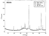
- FIG. 6 is an XRD analysis chart of Experimental Example 1.
- 4 is an enlarged view of an MgO—AlN solid solution peak in an XRD analysis chart of Experimental Example 1.
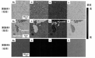
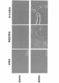
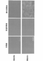
- FIG. It is an EPMA element mapping image of Experimental Examples 1 and 5. It is a microstructure photograph of the bulk material moisture resistance of Example 2, 5 and a water resistance test. 7 is a microstructure photograph of bulk material moisture resistance and water resistance tests of Experimental Examples 8 and 9.
- the ceramic material of the present invention is a ceramic material mainly composed of magnesium, aluminum, oxygen and nitrogen, and has a crystal phase of a MgO—AlN solid solution in which an aluminum nitride component is dissolved in magnesium oxide as a main phase.
- This MgO—AlN solid solution is considered to be equivalent in corrosion resistance to magnesium oxide and superior in moisture resistance and water resistance to magnesium oxide.
- the ceramic material having the MgO—AlN solid solution crystal phase as the main phase also has improved corrosion resistance, moisture resistance, and water resistance.
- the ceramic material of this invention can increase the solid solution amount of an aluminum and a nitrogen component remarkably by adding aluminum nitride and aluminum oxide to magnesium oxide. For this reason, the MgO—AlN solid solution may contain a large amount of aluminum with respect to the solid solution amount of nitrogen.
- the ceramic material of the present invention contains an AlN crystal phase as a subphase, the corrosion resistance tends to decrease. Therefore, the AlN crystal phase is preferably small and more preferably not contained.
- a / B is preferably 0.03 or more. In this way, the mechanical properties can be further improved.
- the molar ratio of magnesium / aluminum in the mixed powder is preferably 0.5 or more.
- the open porosity is preferably 5% or less.
- the open porosity is a value measured by the Archimedes method using pure water as a medium. If the open porosity exceeds 5%, the strength may be reduced, or the material itself may be likely to generate dust by degreasing, and further, dust generation components are likely to accumulate in the pores during material processing or the like, which is not preferable.
- the open porosity is preferably as close to zero as possible. For this reason, there is no lower limit in particular.
- the ceramic material of the present invention may have few different phases.
- the MgO—AlN solid solution of 2 ⁇ 62.3 to 65.2 °.
- the XRD peak area of the (220) plane is b
- the aluminum nitride in the vicinity of 2 ⁇ 36.0 °
- the (a + c + d) / (a + b + c + d) value is preferably 0.1 or less.
- This ceramic material having a small number of different phases for example, a ceramic material having an (a + c + d) / (a + b + c + d) value of 0.1 or less is preferably used for the sputtering target member.
- the sputtering target member contains a heterogeneous phase
- the sputtering rate of the main phase and the heterogeneous phase may be different.
- the heterogeneous phase is small, a decrease in homogeneity of the film to be deposited can be further suppressed, and sputtering is performed. Generation of dust from the target member can be further suppressed.
- the lattice constant of magnesium oxide changes due to the solid solution of aluminum and nitrogen, the lattice constant can be adjusted according to the amount of the solid solution, thereby adjusting the lattice matching with the film forming material.
- the ceramic material of the present invention can be used as a member for a semiconductor manufacturing apparatus.
- the semiconductor manufacturing apparatus member include an electrostatic chuck and a susceptor, a heater, a plate, an inner wall material, a monitoring window, a microwave introduction window, and a microwave coupling antenna used in the semiconductor manufacturing apparatus. Since these materials require excellent corrosion resistance against corrosive gas plasma containing a halogen element, it is preferable to use the ceramic material of the present invention.
- the ceramic material of the present invention can be used for a sputtering target member.
- the sputtering target material of the present invention is a ceramic material mainly composed of magnesium, aluminum, oxygen and nitrogen, and has a crystal phase of MgO—AlN solid solution in which an aluminum nitride component is dissolved in magnesium oxide as a main phase. It may be made of a ceramic material. Since the ceramic material of the present invention maintains the crystal structure of magnesium oxide and has a lower electric resistance, it is preferably used for a sputtering target member. As a sputtering target member, it is good also as what is used for preparation of the tunnel barrier of a magnetic tunnel junction element, for example.
- the ceramic material of the present invention is preferably used for the production of at least one magnetic tunnel junction element among the magnetic head of the hard disk and the magnetoresistive random access memory. Since these require low electrical resistance and high magnetoresistance ratio, it can be said that it is preferable to use the ceramic material of the present invention.
- the ceramic material of the present invention can be produced by firing a mixed powder of magnesium oxide, aluminum nitride and alumina after forming.
- the mixed powder of the raw material is preferably one containing 49% by mass or more of magnesium oxide, aluminum nitride and alumina (aluminum oxide).
- magnesium oxide is 70% by mass or more and 99% in the mixed powder composition. More preferably, the mixture is such that aluminum nitride is 0.5 mass% to 25 mass%, aluminum oxide is 0.5 mass% to 25 mass%, and magnesium oxide is 70 mass% to 90 mass%.
- magnesium oxide is 49% by mass to 99% by mass
- aluminum nitride is 0.5% by mass to 25% by mass
- aluminum oxide is 0%.
- magnesium oxide is 50% by mass to 75% by mass
- aluminum nitride is 5% by mass to 20% by mass
- aluminum oxide is 15% by mass or more. What mixed so that it may become 30 mass% or less is still more preferable.
- the firing temperature is preferably 1650 ° C. or higher, and more preferably 1700 ° C. or higher.
- a calcination temperature of less than 1650 ° C. is not preferable because the intended MgO—AlN solid solution may not be obtained.
- AlN may be contained as a subphase, and it is better to fire at 1700 ° C. or higher in order to obtain high corrosion resistance.
- the upper limit of the firing temperature is not particularly limited, but may be 1850 ° C., for example.
- it is preferable to employ hot press firing for firing, and the press pressure during hot press firing is preferably set to 50 to 300 kgf / cm 2 .
- the atmosphere during firing is preferably an atmosphere that does not affect firing of the oxide raw material, and is preferably an inert atmosphere such as a nitrogen atmosphere, an argon atmosphere, or a helium atmosphere.
- the pressure at the time of molding is not particularly limited, and may be appropriately set to a pressure that can maintain the shape.
- the mixed powder was uniaxially pressed at a pressure of 200 kgf / cm 2 to produce a disk-shaped molded body having a diameter of about 35 mm and a thickness of about 10 mm, and stored in a firing graphite mold.
- -Firing A ceramic material was obtained by hot-press firing the disk-shaped compact.
- the press pressure was 200 kgf / cm 2
- firing was performed at the firing temperature (maximum temperature) shown in Table 1, and an Ar atmosphere was maintained until firing was completed.
- the holding time at the firing temperature was 4 hours.
- Example 4 A ceramic material was obtained in the same manner as in Experimental Example 1 except that the firing temperature was set to 1650 ° C.
- Example 5 A ceramic material was obtained in the same manner as in Experimental Example 1 except that the firing temperature was set to 1500 ° C. using only the MgO raw material.
- Example 6 A ceramic material was obtained in the same manner as in Experimental Example 1 except that the MgO raw material and the Al 2 O 3 raw material were weighed so as to have the mass% shown in Table 1 and the firing temperature was set to 1650 ° C.
- Example 22 Except that the MgO raw material and the Al 2 O 3 raw material were weighed so as to have the mass% shown in Table 3, the mixing process was performed in the same manner as in Experimental Example 1 to obtain a mixed powder.
- the above-mentioned mixed raw material was filled in a graphite crucible with a lid, and the molded body was embedded in the filled mixed raw material.
- a ceramic material was obtained by performing a firing step of firing the cylindrical shaped body at normal pressure.
- firing was performed at the firing temperature (maximum temperature) shown in Table 3, and an Ar atmosphere was maintained until firing was completed.
- the holding time at the firing temperature was 4 hours.
- the peak interval and integral width between the MgO—AlN solid solution and magnesium oxide were calculated as follows.
- (2) -1 Calculation of peak interval (peak shift)
- the peak interval (peak shift) is calculated for the (220) plane of the MgO-AlN solid solution. evaluated.
- the difference between the peak top diffraction angle of the (220) plane of the MgO—AlN solid solution and the diffraction angle (62.3 °) of the (220) plane of magnesium oxide in ICDD78-0430 was taken as the peak interval.
- the integral width was calculated in order to relatively compare the crystallinity of the MgO-AlN solid solution.
- the integral width was calculated by dividing the peak area of the (200) peak of the MgO—AlN solid solution by the peak top intensity (Imax).
- the peak area was obtained by integrating the intensity by subtracting the background in the range of ⁇ 1 ° to + 1 ° from the diffraction angle of the peak top.
- the calculation formula is shown below.
- the background was the peak intensity at a diffraction angle of -1 ° from the peak top.
- the integral width of the (111) plane of the NIST Si standard sample (SRM640C) calculated using the above method was 0.15 °.
- the A / B value was determined.
- the XRD peak intensity B is the XRD peak background of the (220) plane of the MgO—AlN solid solution.
- the integrated intensity was excluded.
- the calculation was performed using commercially available software JADE5 manufactured by MDI.
- the ratio of the XRD peak area was calculated by the following method.
- 2 ⁇ The XRD peak area of the (400) plane of spinel (MgAl 2 O 4 ) near 45.0 ° is c
- the XRD peak area of the (002) plane of aluminum nitride (AlN) near 2 ⁇ 36.0 ° is d.
- the XRD peak areas a, b, c, and d were the peak areas at the respective angles obtained from the peak search function of JADE5 manufactured by commercially available software MDI.
- the ratio between the peak area a and the peak area b and the a / b value were also determined using the above calculation method.
- Moisture resistance A powder obtained by pulverizing each material to a median diameter of 10 ⁇ m or less in a mortar was prepared and exposed to a saturated water vapor pressure atmosphere at room temperature for 4 days. Thereafter, the amount of dehydration between 40 and 500 ° C. was measured with a TG-DTA apparatus.
- Fracture toughness was evaluated by the SEPB method according to JIS-R1607.
- volume resistivity measurement The volume resistivity was measured in the atmosphere at room temperature by a method according to JIS-C2141.
- the shape of the test piece was 50 mm in diameter (0.5 to 1 mm), each electrode was formed of silver so that the main electrode had a diameter of 20 mm, the guard electrode had an inner diameter of 30 mm, an outer diameter of 40 mm, and the applied electrode had a diameter of 40 mm.
- the applied voltage was 2 kV / mm, the current value at 1 minute after the voltage application was read, and the room temperature volume resistivity was calculated from the current value.
- Experimental Examples 1, 3, 5, 12, and 23 to 28 were measured at 600 ° C. in a vacuum (0.01 Pa or less) by the same method.
- the shape of the test piece was 50 mm in diameter (0.5 to 1 mm), each electrode was formed of silver so that the main electrode had a diameter of 20 mm, the guard electrode had an inner diameter of 30 mm, an outer diameter of 40 mm, and the applied electrode had a diameter of 40 mm.
- the applied voltage was 500 V / mm, the current value at 1 hour after voltage application was read, and the volume resistivity was calculated from the current value.
- “aEb” represents a ⁇ 10 b
- “1E16” represents 1 ⁇ 10 16 .
- the ceramic materials of Experimental Examples 1 to 3, 7 to 17, 21, and 24 to 28 have the (111) plane, (200) plane, and (220) plane as a result of the crystal phase evaluation.
- Magnesium-aluminum oxynitride (Mg—Al—O—N) or spinel (MgAl 2 O) containing the MgO—AlN solid solution (MgO—AlNss) appearing as the main phase and having an XRD peak at least 2 ⁇ 47 to 49 °.
- FIG. 1 shows an XRD analysis chart of Experimental Example 1
- FIG. 2 shows an enlarged XRD peak of the MgO—AlN solid solution of Experimental Example 1
- Tables 1 and 3 show (111) of the MgO—AlN solid solutions of Experimental Examples 1 to 28. , (200), (220) plane peak top, MgO—AlN solid solution (220) plane XRD peak top and magnesium oxide peak top spacing (peak shift), and MgO—AlN solid solution (200) plane XRD peak Indicates the integral width of.
- the main phase refers to a component having a volume ratio of 50% or more
- the subphase refers to a phase in which an XRD peak is identified other than the main phase. Since the area ratio in the cross-sectional observation is considered to reflect the volume ratio, the main phase is a region having an area of 50% or more in the EPMA element mapping image, and the subphase is a region other than the main phase.
- Experimental Example 20 included the three components MgO—AlN solid solution, magnesium-aluminum oxynitride, and spinel as in Experimental Example 1 and the like, but there was no bias in the amount of each component, and none of the components became the main phase. It was a composite material.
- FIG. 3 shows an EPMA element mapping image of Experimental Example 1.
- FIG. 3 shows that the main phase portion of Experimental Example 1 is mainly composed of Mg and O, but Al and N are also detected at the same time, so that it is the MgO—AlN solid solution shown in FIGS.
- a spinel part and a small amount of magnesium-aluminum oxynitride part are observed as subphases.
- the area ratio of the MgO—AlN solid solution in FIG. 3 was about 86%, and it was found that Experimental Example 1 was mainly composed of MgO—AlN solid solution. The same analysis was performed for the other experimental examples.
- the area ratios of the MgO—AlN solid solutions in Experimental Examples 15, 26, and 28 were about 75%, about 91%, and about 99%, respectively, and the MgO—AlN solid solution was mainly used. It turns out to be a phase.
- the determination of the main phase and the sub phase is performed by EPMA element mapping.
- other methods may be adopted as long as the volume ratio of each phase can be identified. .
- the EPMA element mapping image is color-coded into red, orange, yellow, yellow green, green, blue, and indigo according to the concentration. Red represents the highest concentration, indigo represents the lowest concentration, and black represents zero. .
- FIG. 3 is displayed in monochrome, the original colors in FIG. 3 will be described below.
- Mg has an orange background with blue dots
- Al has a blue background with blue dots
- N has a blue background with blue dots
- O has a blue background. It was orange and the dot was red.
- Mg is orange in ground color (MgO—AlNss)
- island parts MgAl 2 O 4
- linear parts Mg—Al—O—N
- Al ground color Is blue
- islands and line parts are orange
- N ground color is blue
- island parts are indigo and line parts are green
- O ground color is orange
- island parts are red
- line parts are green.
- Mg and O were red
- Al and N were black.
- the ceramic materials of Experimental Examples 4 and 23 both contained the MgO—AlN solid solution described above as the main phase, but Experimental Example 23 included AlN as the subphase. 4 contained spinel and AlN as subphases. Table 1 shows the interval (peak shift) between the XRD peak of the MgO—AlN solid solution of Experimental Examples 4 and 23 and the XRD peak of magnesium oxide. As in Experimental Example 4, it was speculated that the reaction did not occur sufficiently at a firing temperature of 1650 ° C. and the amount of solid solution was small. Since the reaction hardly occurred at the firing temperature of 1600 ° C., the MgO—AlN solid solution was not generated in the ceramic materials of Experimental Examples 18 and 19.
- the ceramic material of Experimental Example 5 contains MgO as the main phase
- the ceramic material of Experimental Example 6 contains spinel as the main phase and MgO as the subphase
- the ceramic material of Experimental Example 22 contained MgO as the main phase and spinel as the subphase. Therefore, it was found that if the AlN component was not contained in the raw material, the Al component was not dissolved in MgO by either hot pressing or normal pressure firing.
- the ceramic materials of Experimental Examples 1 to 3, 7 to 13, 17, 20, and 21 have a moisture reduction rate (mass reduction rate of 40 to 500 ° C. by TG-DTA) of 2% or less.
- the ceramic materials Nos. 14 to 16 had a moisture reduction rate of 3% or less, and had much higher moisture resistance than the MgO ceramics, that is, the ceramic material of Experimental Example 5.
- microstructure photographs of Experimental Examples 2 and 5 are shown in FIG. 4, and microstructure photographs of Experimental Examples 8 and 9 are shown in FIG.
- the moisture resistance of the bulk material it is better that the solid solution amount is large, and the peak shift from the magnesium oxide of the MgO—AlN solid solution (220) surface is 0.2 ° or more.
- the peak shift from magnesium oxide on the (220) plane of the MgO—AlN solid solution is less than 0.03 °, the change occurs at 40% or more of the surface and the moisture resistance is low, and the peak shift is 0.03 ° or more and 0.
- the angle was less than 2 ° the moisture resistance was good, and when the peak shift was 0.2 ° or more, the moisture resistance was even better.
- the XRD peak of the (220) plane of the MgO—AlN solid solution is between the cubic peak of magnesium oxide and the cubic peak of aluminum nitride, which is 62.33 ° or more and less than 62.50 ° (2 ⁇ ).
- the water resistance of the bulk material is good when the Al and N components in MgO have a large amount of solid solution and are homogeneous. That is, when the peak shift from the magnesium oxide on the (220) plane of the MgO—AlN solid solution is 0.05 ° or less, 40% or more of the surface elutes and the water resistance is low, and the peak shift is 0.05 ° or more and 0.0.
- a material of less than 42 °, or a material having a peak shift of 0.42 ° or more but an integrated width of (200) plane of MgO—AlN solid solution exceeding 0.35 ° has good water resistance and a peak shift of 0.
- a material having an angle of 42 ° or more and an integral width of 0.35 ° or less was further excellent in water resistance. That is, the XRD peak on the (220) plane of the MgO—AlN solid solution is between the cubic peak of magnesium oxide and the cubic peak of aluminum nitride, which is 62.35 ° or more and less than 62.72 ° (2 ⁇ ). Or a material having an (220) plane XRD peak of 62.72 ° or more but an (200) plane integration width exceeding 0.35 ° has good water resistance, and the (220) plane XRD peak Was 62.72 ° or more and the integral width was 0.35 ° or less, the water resistance was even better.
- the ceramic materials of Experimental Examples 1 to 3, 12, and 14 to 16 were found to have high corrosion resistance comparable to that of the MgO ceramic of Experimental Example 5 from the results of the etching rate. Although the ceramic materials of Experimental Examples 4, 7 to 11, 13, and 21 are slightly inferior in corrosion resistance to MgO of Experimental Example 5 from the result of the etching rate, the ceramic material of Experimental Example 6, that is, spinel is the main phase. It was found that the material and corrosion resistance were higher than yttria (etching rate of about 240 nm / h) not shown in the table.
- Experimental Examples 1 to 3 and 7 to 15 include a magnesium-aluminum oxynitride (Mg—Al—O—N) phase as a subphase, but the mechanical properties increase as the content of the Mg—Al—O—N phase increases. Had improved.
- Mg—Al—O—N magnesium-aluminum oxynitride
- the mechanical properties increase as the content of the Mg—Al—O—N phase increases.
- Tables 2 and 4 show the A / B values.
- the larger A / B means that the amount of Mg—Al—O—N is larger.
- the volume resistivity at 600 ° C. of Experimental Example 5 and Experimental Example 12 is 2 ⁇ 10 12 ⁇ cm and 2 ⁇ 10 10 ⁇ cm, respectively, and the ceramic material of Experimental Example 12 is lower than MgO (Experimental Example 5). It was found to have electrical resistance. In addition, the ceramic materials of Experimental Examples 1, 3, 23 to 28 were found to have a lower electrical resistance than Experimental Example 5 as in Experimental Example 12.
- the XRD peak area of the (400) plane of spinel (MgAl 2 O 4 ) near 2 ⁇ 45.0 °
- the XRD peak of the (002) plane of aluminum nitride (AlN) near 2 ⁇ 36.0 °.
- Tables 2 and 4 show the values (a + c + d) / (a + b + c + d) when the area is d.
- the (a + c + d) / (a + b + c + d) value is 0.1 or less. Therefore, these ceramic materials with few different phases are preferably used for the sputtering target member.
- Example 14 a was 782 counts, b was 123644 counts, c was 2613 counts, d was 0 counts, and the (a + c + d) / (a + b + c + d) value was 0.027.
- Example 23 it was found that a was 0 count, b was 109166 count, c was 0 count, d was 2775 count, and (a + c + d) / (a + b + c + d) value was 0.025, indicating that there were few heterogeneous phases.
- the produced ceramic material maintains the crystal structure of magnesium oxide and has an electric resistance lower than that of magnesium oxide. This seems to be because the carriers in magnesium oxide increased due to the solid solution of aluminum and nitrogen in the magnesium oxide crystal. For this reason, when a magnetic tunnel junction element such as a magnetic head of a hard disk and a magnetoresistive random access memory is manufactured using this material as a sputtering target, an improvement in characteristics of electric resistance and / or magnetoresistance ratio is expected.
- the ceramic material of the present invention is used, for example, for semiconductor manufacturing apparatus members such as electrostatic chucks, susceptors, heaters, plates, inner wall materials, monitoring windows, microwave introduction windows, and microwave coupling antennas.
- the ceramic material of this invention is used for the sputtering target member for preparation of magnetic tunnel junction elements, such as a magnetic head of a hard disk, and a magnetoresistive random access memory, for example.
Landscapes
- Chemical & Material Sciences (AREA)
- Engineering & Computer Science (AREA)
- Ceramic Engineering (AREA)
- Manufacturing & Machinery (AREA)
- Materials Engineering (AREA)
- Organic Chemistry (AREA)
- Structural Engineering (AREA)
- Inorganic Chemistry (AREA)
- Chemical Kinetics & Catalysis (AREA)
- Mechanical Engineering (AREA)
- Metallurgy (AREA)
- Physics & Mathematics (AREA)
- Thermal Sciences (AREA)
- Container, Conveyance, Adherence, Positioning, Of Wafer (AREA)
- Ceramic Products (AREA)
- Compositions Of Oxide Ceramics (AREA)
- Drying Of Semiconductors (AREA)
- Physical Vapour Deposition (AREA)
Abstract
Description
・調合
MgO原料、Al2O3原料及びAlN原料を、表1に示す質量%となるように秤量し、イソプロピルアルコールを溶媒とし、ナイロン製のポット、直径5mmのアルミナ玉石を用いて4時間湿式混合した。混合後スラリーを取り出し、窒素気流中110℃で乾燥した。その後、30メッシュの篩に通し、混合粉末とした。なお、この混合粉末のMg/Alのモル比は2.9である。
・成形
混合粉末を、200kgf/cm2の圧力で一軸加圧成形し、直径35mm、厚さ10mm程度の円盤状成形体を作製し、焼成用黒鉛モールドに収納した。
・焼成
円盤状成形体をホットプレス焼成することによりセラミックス材料を得た。ホットプレス焼成では、プレス圧力を200kgf/cm2とし、表1に示す焼成温度(最高温度)で焼成し、焼成終了までAr雰囲気とした。焼成温度での保持時間は4時間とした。
焼成温度を1650℃に設定した以外は、実験例1と同様にしてセラミックス材料を得た。
MgO原料のみを用いて焼成温度を1500℃に設定した以外は、実験例1と同様にしてセラミックス材料を得た。
MgO原料及びAl2O3原料を、表1に示す質量%となるように秤量し、焼成温度を1650℃に設定した以外は、実験例1と同様にしてセラミックス材料を得た。
MgO原料、Al2O3原料及びAlN原料を、表1に示す質量%となるように秤量し、表1に示す焼成温度(最高温度)に設定した以外は実験例1と同様にしてセラミックス材料を得た。
MgO原料、Al2O3原料及びAlN原料を、表3に示す質量%となるように秤量し、混合粉末の成形圧力を100kgf/cm2、サンプルの直径を50mm、焼成雰囲気をN2、焼成温度(最高温度)を表3に示す値に設定した以外は実験例1と同様にしてセラミックス材料を得た。
MgO原料、Al2O3原料を、表3に示す質量%となるように秤量した以外は、実験例1と同様にして調合工程を行い混合粉末を得た。混合粉末を、100kgf/cm2の圧力で一軸加圧成形し、直径20mm、厚さ15mm程度の円柱状成形体を作製し、作製された成形体を3000kgf/cm2でCIP成形する成形工程を行った。蓋付の黒鉛製るつぼに上記の混合原料を充填し、充填した混合原料中に成形体を埋め込んだ。円柱状成形体を常圧焼成する焼成工程を行い、セラミックス材料を得た。焼成工程では、表3に示す焼成温度(最高温度)で焼成し、焼成終了までAr雰囲気とした。焼成温度での保持時間は4時間とした。
MgO、Al2O3及びAlNの各原料を、表3に示す質量%となるように秤量し、調合時の玉石を直径20mmの鉄芯入ナイロンボールとし、成形時の一軸加圧成形時の圧力を100kgf/cm2として直径50mm、厚さ20mm程度の円盤状成形体を作製し、表3に示す焼成温度(最高温度)に設定し、焼成時の雰囲気をN2雰囲気とした以外は実験例1と同様にしてセラミックス材料を得た。
実験例1~28で得られた各材料を各種評価用に加工し、以下の評価を行った。各評価結果を表1~4に示す。なお、実験例1~17では、直径50mmのサンプルも作製したが、表1~4と同様の結果が得られた。
純水を媒体としたアルキメデス法により測定した。
材料を乳鉢で粉砕し、X線回折装置により結晶相を同定した。測定条件はCuKα,40kV,40mA,2θ=5-70°とし、封入管式X線回折装置(ブルカー・エイエックスエス製 D8 ADVANCE)を使用した。測定のステップ幅は0.02°とし、ピークトップの回折角を特定する場合は内部標準としてNIST製Si標準試料粉末(SRM640C)を10質量%添加し、ピーク位置補正した。酸化マグネシウムのピークトップの回折角は、ICDD78-0430の値とした。MgO-AlN固溶体と酸化マグネシウムとのピーク間隔、積分幅は下記のとおり算出した。
(2)-1 ピーク間隔(ピークシフト)の計算
MgO-AlN固溶体中のAl、N固溶量を相対比較するため、MgO-AlN固溶体の(220)面を対象としてピーク間隔(ピークシフト)を評価した。MgO-AlN固溶体の(220)面のピークトップの回折角と、ICDD78-0430にある酸化マグネシウムの(220)面の回折角(62.3°)の差をピーク間隔とした。
(2)-2 積分幅の計算
MgO-AlN固溶体の結晶性を相対比較するため、積分幅を計算した。積分幅は、MgO-AlN固溶体の(200)ピークのピーク面積をピークトップの強度(Imax)で除して計算した。ピーク面積は、ピークトップの回折角から-1°~+1°の範囲において、バックグラウンドを差し引いて、強度を積算することで得た。計算式を下記に示す。なお、バックグラウンドはピークトップから-1°の回折角におけるピーク強度とした。上記の手法を用いて計算したNIST製Si標準試料(SRM640C)の(111)面の積分幅は0.15°であった。
(積分幅)=(ΣI(2θ)×(ステップ幅))/Imax
(2)-3 マグネシウム-アルミニウム酸窒化物相とMgO-AlN固溶体のXRDピーク強度比の計算
副相として含まれるマグネシウム-アルミニウム酸窒化物相の含有割合を相対比較するため、下記の方法を用いてマグネシウム-アルミニウム酸窒化物相とMgO-AlN固溶体のXRDピーク強度の比を計算した。マグネシウム-アルミニウム酸窒化物相の2θ=47~49°のXRDピーク強度をA、2θ=62.3~65.2°のMgO-AlN固溶体の(220)面のXRDピーク強度をBとしたときのA/B値を求めた。ここでは、XRDピーク強度Aは、2θ=47~49°のXRDピークのバックグラウンドを除いた積分強度とし、XRDピーク強度Bは、MgO-AlN固溶体の(220)面のXRDピークのバックグラウンドを除いた積分強度とした。なお、算出には、市販のソフトウエアMDI社製JADE5を用いて求めた。
(2)-4 異相の含有割合の計算
次に、全体に対する異相の割合を相対比較するため、以下の方法によってXRDピーク面積の比を算出した。マグネシウム-アルミニウム酸窒化物相の2θ=47~49°のXRDピーク面積をa、2θ=62.3~65.2°のMgO-AlN固溶体の(220)面のXRDピーク面積をb、2θ=45.0°近傍のスピネル(MgAl2O4)の(400)面のXRDピーク面積をc、2θ=36.0°近傍の窒化アルミニウム(AlN)の(002)面のXRDピーク面積をdとしたときの、(a+c+d)/(a+b+c+d)値を求めた。ここでは、XRDピーク面積a、b、c、dは市販のソフトウエアMDI社製JADE5のピークサーチ機能から求められたそれぞれの上記角度のピーク面積とした。JADE5のピークサーチ条件は、フィルタータイプについては放物線フィルタ、ピーク位置定義についてはピークトップ、しきい値と範囲については、しきい値σ=3.00、ピーク強度%カットオフ=0.1、BG決定の範囲=1.0、BG平均化のポイント数=7、角度範囲=5.0~70.0°とし、可変フィルタ長(データポイント)ON、Kα2ピークを消去ON、現存のピークリストを消去ONとした。また、上記の計算方法を用いて、ピーク面積aとピーク面積bの比、a/b値も求めた。
各材料の表面を鏡面に研磨し、ICPプラズマ耐食試験装置を用いて下記条件の耐食試験を行った。段差計により測定したマスク面と暴露面との段差を試験時間で割ることにより各材料のエッチングレートを算出した。
ICP:800W、バイアス:450W、導入ガス:NF3/O2/Ar=75/35/100sccm 0.05Torr、暴露時間:10h、試料温度:室温
EPMAを用いて、構成元素の検出及び同定と、各構成元素の濃度分析を行った。
各材料を乳鉢にてメジアン径10μm以下まで粉砕した粉末を作製し、室温で飽和水蒸気圧雰囲気に4日間暴露した。その後、TG-DTA装置にて40~500℃間の脱水量を測定した。
各材料の表面を鏡面研磨し、40℃,相対湿度90%の雰囲気下に28日間暴露した。その後、走査型電子顕微鏡(フィリップス社製XL30)にて試料表面を観測し、変化のないものを(○)、表面の40%以上に針状や粒状の析出物が生じたものを(×)、その中間を(△)とした。
各材料の表面を鏡面研磨し、室温で水中に15日間浸漬した。その後、走査型電子顕微鏡にて試料表面を観測し、変化のないものを(○)、表面の40%以上に溶出した痕跡が見られるものを(×)、その中間を(△)とした。
JIS-R1607にしたがって、SEPB法により破壊靱性を評価した。
JIS-R1601に準拠した曲げ強度試験によって測定した。
JIS-C2141に準じた方法により、大気中、室温にて測定した。試験片形状は直径50mm×(0.5~1mm)とし、主電極は直径20mm、ガード電極は内径30mm、外径40mm、印加電極は直径40mmとなるよう各電極を銀で形成した。印加電圧は2kV/mmとし、電圧印加後1分時の電流値を読み取り、その電流値から室温体積抵抗率を算出した。
また、実験例1,3,5,12,23~28について、同様の方法により、真空中(0.01Pa以下)、600℃にて測定した。試験片形状は直径50mm×(0.5~1mm)とし、主電極は直径20mm、ガード電極は内径30mm、外径40mm、印加電極は直径40mmとなるよう各電極を銀で形成した。印加電圧は500V/mmとし、電圧印加後1時間時の電流値を読み取り、その電流値から体積抵抗率を算出した。なお、表2,4の体積抵抗率において、「aEb」は、a×10bを表し、例えば「1E16」は1×1016を表す。
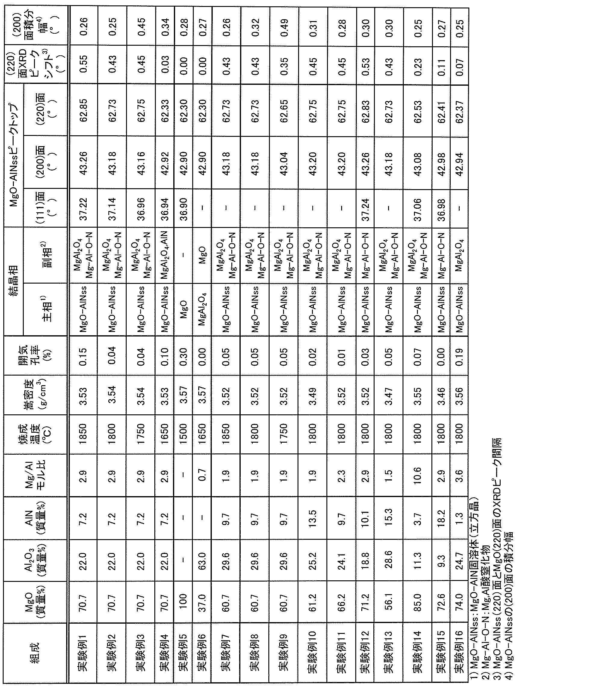
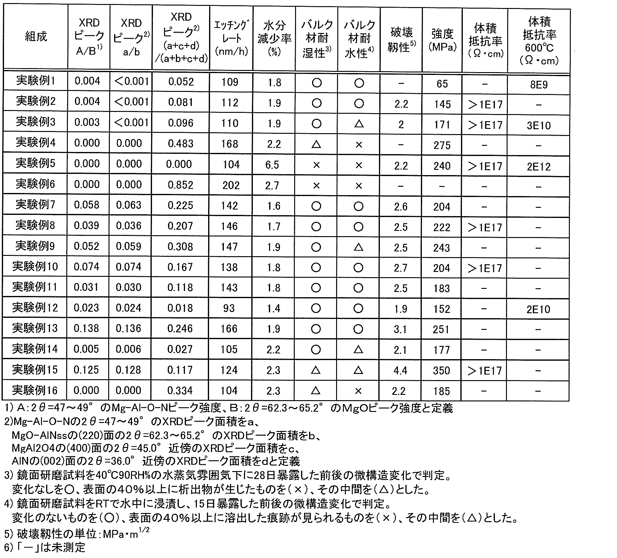
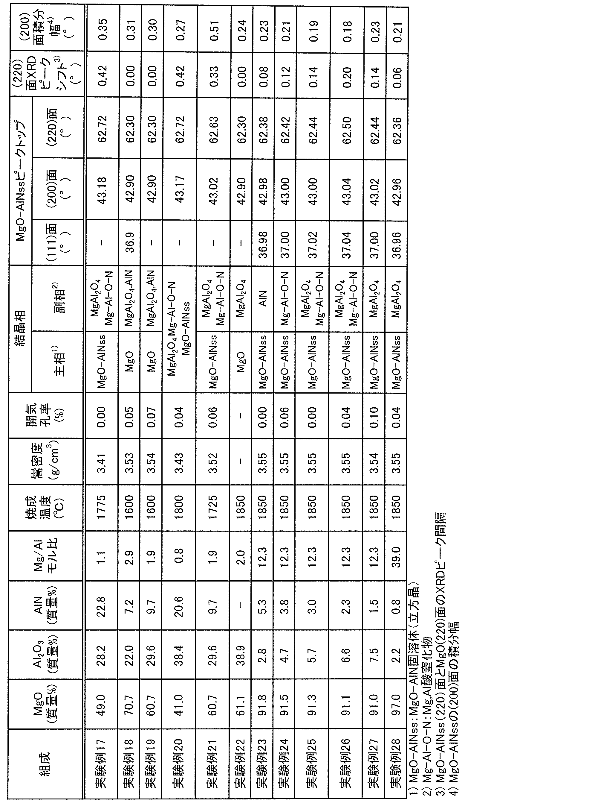
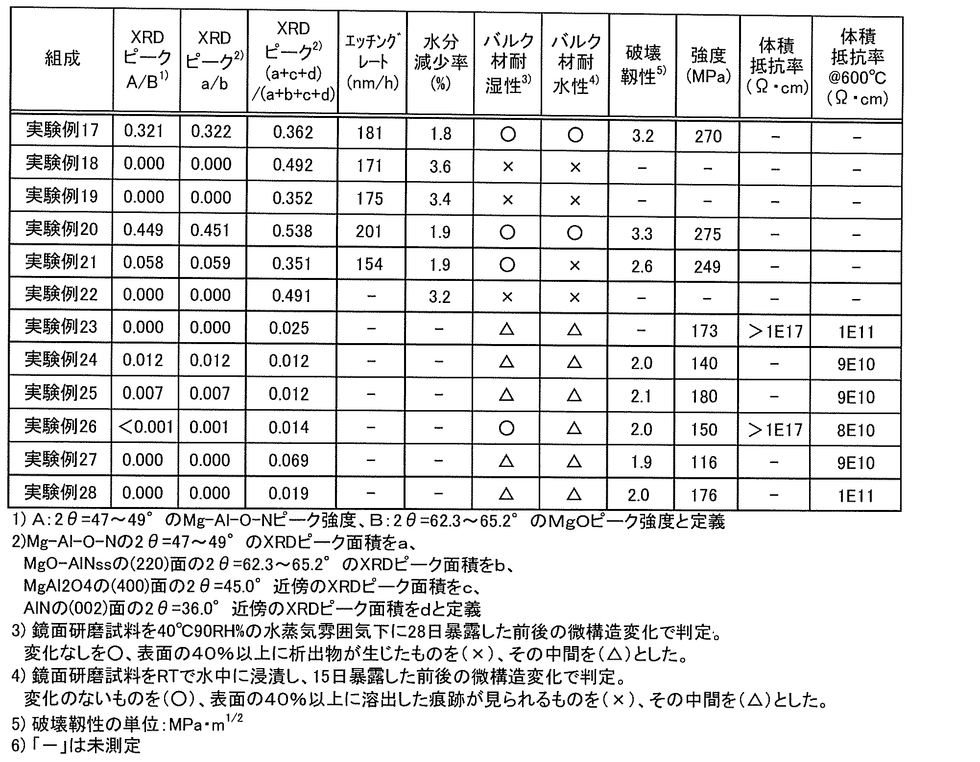
表1~4に示すように、実験例1~3,7~17,21,24~28のセラミックス材料は、結晶相評価の結果、(111)面、(200)面及び(220)面のXRDピークが酸化マグネシウムの立方晶のピークと窒化アルミニウムの立方晶のピークとの間である2θ=36.9~39°,42.9~44.8°,62.3~65.2°に現れるMgO-AlN固溶体(MgO-AlNss)を主相として含み、少なくとも2θ=47~49°にXRDのピークを有するマグネシウム-アルミニウム酸窒化物(Mg-Al-O-N)やスピネル(MgAl2O4)を副相として含んでいたが、AlNは含まれていなかった。代表例として図1に実験例1のXRD解析チャート、図2に実験例1のMgO-AlN固溶体のXRDピーク拡大図、表1,3に実験例1~28のMgO-AlN固溶体の(111)、(200)、(220)面ピークトップ、MgO-AlN固溶体(220)面のXRDピークトップと酸化マグネシウムピークトップとの間隔(ピークシフト)、及びMgO-AlN固溶体の(200)面のXRDピークの積分幅を示す。なお、実験例6~11,13,16,17,19~21では、スピネルピークとMgO-AlN固溶体の(111)面のピークとの重なりが著しく、(111)面のピークトップが判別できなかったため、これらの(111)面のピークトップの値は、表3に記載していない。ピークシフトが大きいほど固溶量が多く、積分幅が小さいほど固溶状態が均質と考えられる。なお、実験例2,3,7~17,20,21,24~28のXRD解析チャートは、実験例1に含まれるMgO-AlN固溶体、マグネシウム-アルミニウム酸窒化物、スピネルの含有量が変化したものであり、図示を省略する。ここで、主相とは、体積割合において50%以上を有する成分をいい、副相とは、主相以外でXRDピークが同定された相をいう。断面観察における面積比は体積割合を反映すると考えられるため、主相はEPMA元素マッピング像で50%以上の面積を有する領域とし、副相は主相以外の領域とする。実験例20は、実験例1などと同様にMgO-AlN固溶体、マグネシウム-アルミニウム酸窒化物及びスピネルの三成分を含んでいたが、各成分の量に偏りがなく、どの成分も主相とならない複合材であった。このため、表3の主相、副相の欄には上記三成分を記載した。図3に実験例1のEPMA元素マッピング像を示す。図3より、実験例1の主相部は主としてMgとOで構成されるが、Al、Nも同時に検出されるため図1、2に示したMgO-AlN固溶体であることが示される。また、副相としてスピネル部と少量のマグネシウム-アルミニウム酸窒化物部が認められる。図3のMgO-AlN固溶体の面積比は約86%であり、実験例1はMgO-AlN固溶体が主相であることがわかった。その他の実験例についても同様の解析を行い、例えば実験例15,26,28のMgO-AlN固溶体の面積比はそれぞれ約75%、約91%、約99%であり、MgO-AlN固溶体が主相であることがわかった。なお、ここでは、一例として、主相と副相との判定をEPMA元素マッピングにて行うものとしたが、各相の体積割合を識別できる方法であれば、他の方法を採用してもよい。
Claims (21)
- マグネシウム、アルミニウム、酸素及び窒素を主成分とするセラミックス材料であって、
酸化マグネシウムに窒化アルミニウムが固溶したMgO-AlN固溶体の結晶相を主相とする、
セラミックス材料。 - 前記MgO-AlN固溶体は、CuKα線を用いたときの(200)面及び(220)面のXRDピークが酸化マグネシウムの立方晶のピークと窒化アルミニウムの立方晶のピークとの間である2θ=42.9~44.8°,62.3~65.2°に現れる、請求項1に記載のセラミックス材料。
- 前記MgO-AlN固溶体は、CuKα線を用いたときの(111)面、(200)面及び(220)面のXRDピークが酸化マグネシウムの立方晶のピークと窒化アルミニウムの立方晶のピークとの間である2θ=36.9~39°,42.9~44.8°,62.3~65.2°に現れる、請求項1に記載のセラミックス材料。
- 前記MgO-AlN固溶体の(200)面、(220)面のXRDピークがそれぞれ2θ=42.92°以上,62.33°以上に現れる、請求項2又は3に記載のセラミックス材料。
- 前記MgO-AlN固溶体の(200)面、(220)面のXRDピークがそれぞれ2θ=42.95°以上,62.35°以上に現れる、請求項2~4のいずれか1項に記載のセラミックス材料。
- 前記MgO-AlN固溶体の(200)面、(220)面のXRDピークがそれぞれ2θ=43.04°以上,62.50°以上に現れる、請求項2~5のいずれか1項に記載のセラミックス材料。
- 前記MgO-AlN固溶体の(200)面、(220)面のXRDピークがそれぞれ2θ=43.17°以上,62.72°以上に現れる、請求項2~6のいずれか1項に記載のセラミックス材料。
- 前記MgO-AlN固溶体の(200)面のXRDピークの積分幅が0.50°以下である、請求項1~7のいずれか1項に記載のセラミックス材料。
- 前記MgO-AlN固溶体の(200)面のXRDピークの積分幅が0.35°以下である、請求項1~8のいずれか1項に記載のセラミックス材料。
- AlN結晶相を含まない、請求項1~9のいずれか1項に記載のセラミックス材料。
- CuKα線を用いたときのXRDピークが少なくとも2θ=47~49°に現れるマグネシウム-アルミニウム酸窒化物相を副相として含む、請求項1~10のいずれか1項に記載のセラミックス材料。
- 前記マグネシウム-アルミニウム酸窒化物相の2θ=47~49°のXRDピーク強度をA、前記MgO-AlN固溶体の(220)面の2θ=62.3~65.2°のXRDピーク強度をBとしたとき、A/Bが0.03以上である、請求項11に記載のセラミックス材料。
- 前記A/Bが0.14以下である、請求項12に記載のセラミックス材料。
- 前記マグネシウム-アルミニウム酸窒化物相の2θ=47~49°のXRDピーク面積をa、前記MgO-AlN固溶体の(220)面の2θ=62.3~65.2°のXRDピーク面積をb、スピネル(MgAl2O4)の(400)面の2θ=45.0°のXRDピーク面積をc、窒化アルミニウム(AlN)の(002)面の2θ=36.0°のXRDピーク面積をdとしたとき、(a+c+d)/(a+b+c+d)値が0.1以下である、請求項1~13のいずれか1項に記載のセラミックス材料。
- 混合粉末組成は、酸化マグネシウムが49質量%以上99質量%以下、窒化アルミニウムが0.5質量%以上25質量%以下、酸化アルミニウムが0.5質量%以上30質量%以下である、請求項1~14のいずれか1項に記載のセラミックス材料。
- 混合粉末組成は、酸化マグネシウムが50質量%以上75質量%以下、窒化アルミニウムが5質量%以上20質量%以下、酸化アルミニウムが15質量%以上30質量%以下である、請求項1~15のいずれか1項に記載のセラミックス材料。
- 請求項1~16のいずれか1項に記載のセラミックス材料からなる、半導体製造装置用部材。
- 請求項1~16のいずれか1項に記載のセラミックス材料からなる、スパッタリングターゲット部材。
- 磁気トンネル接合素子のトンネル障壁の作製に使用される、請求項18に記載のスパッタリングターゲット部材。
- ハードディスクの磁気ヘッド及び磁気抵抗ランダムアクセスメモリのうち少なくとも1つの前記磁気トンネル接合素子の作製に使用される、請求項19に記載のスパッタリングターゲット部材。
- 酸化マグネシウムと酸化アルミニウムと窒化アルミニウムの混合粉末を不活性雰囲気下でホットプレス焼成し、請求項1~16のいずれか1項に記載のセラミックス材料を製造する、セラミックス材料の製造方法。
Priority Applications (4)
| Application Number | Priority Date | Filing Date | Title |
|---|---|---|---|
| KR1020127013650A KR101881171B1 (ko) | 2010-10-25 | 2011-10-11 | 세라믹스 재료, 반도체 제조 장치용 부재, 스퍼터링 타겟 부재 및 세라믹스 재료의 제조 방법 |
| JP2012524038A JP5680644B2 (ja) | 2010-10-25 | 2011-10-11 | セラミックス材料、半導体製造装置用部材、スパッタリングターゲット部材及びセラミックス材料の製造方法 |
| CN201180004701.7A CN102639463B (zh) | 2010-10-25 | 2011-10-11 | 陶瓷材料、半导体制造装置用构件、溅射靶材及陶瓷材料的制造方法 |
| US13/478,591 US8541328B2 (en) | 2010-10-25 | 2012-05-23 | Ceramic material, member for semiconductor manufacturing equipment, sputtering target member and method for producing ceramic material |
Applications Claiming Priority (6)
| Application Number | Priority Date | Filing Date | Title |
|---|---|---|---|
| JP2010-238999 | 2010-10-25 | ||
| JP2010238999 | 2010-10-25 | ||
| JP2011-135313 | 2011-06-17 | ||
| JP2011135313 | 2011-06-17 | ||
| PCT/JP2011/069491 WO2012056808A1 (ja) | 2010-10-25 | 2011-08-29 | セラミックス材料、半導体製造装置用部材、スパッタリングターゲット部材及びセラミックス材料の製造方法 |
| JPPCT/JP2011/069491 | 2011-08-29 |
Related Child Applications (1)
| Application Number | Title | Priority Date | Filing Date |
|---|---|---|---|
| US13/478,591 Continuation US8541328B2 (en) | 2010-10-25 | 2012-05-23 | Ceramic material, member for semiconductor manufacturing equipment, sputtering target member and method for producing ceramic material |
Publications (1)
| Publication Number | Publication Date |
|---|---|
| WO2012056876A1 true WO2012056876A1 (ja) | 2012-05-03 |
Family
ID=45993538
Family Applications (3)
| Application Number | Title | Priority Date | Filing Date |
|---|---|---|---|
| PCT/JP2011/069491 Ceased WO2012056808A1 (ja) | 2010-10-25 | 2011-08-29 | セラミックス材料、半導体製造装置用部材、スパッタリングターゲット部材及びセラミックス材料の製造方法 |
| PCT/JP2011/073771 Ceased WO2012056918A1 (ja) | 2010-10-25 | 2011-10-11 | 静電チャック |
| PCT/JP2011/073330 Ceased WO2012056876A1 (ja) | 2010-10-25 | 2011-10-11 | セラミックス材料、半導体製造装置用部材、スパッタリングターゲット部材及びセラミックス材料の製造方法 |
Family Applications Before (2)
| Application Number | Title | Priority Date | Filing Date |
|---|---|---|---|
| PCT/JP2011/069491 Ceased WO2012056808A1 (ja) | 2010-10-25 | 2011-08-29 | セラミックス材料、半導体製造装置用部材、スパッタリングターゲット部材及びセラミックス材料の製造方法 |
| PCT/JP2011/073771 Ceased WO2012056918A1 (ja) | 2010-10-25 | 2011-10-11 | 静電チャック |
Country Status (6)
| Country | Link |
|---|---|
| US (2) | US8541328B2 (ja) |
| JP (2) | JP5683602B2 (ja) |
| KR (2) | KR101682749B1 (ja) |
| CN (2) | CN103201235B (ja) |
| TW (2) | TWI590374B (ja) |
| WO (3) | WO2012056808A1 (ja) |
Cited By (2)
| Publication number | Priority date | Publication date | Assignee | Title |
|---|---|---|---|---|
| WO2016002480A1 (ja) * | 2014-06-30 | 2016-01-07 | 日本碍子株式会社 | MgO系セラミックス膜、半導体製造装置用部材及びMgO系セラミックス膜の製法 |
| JP2016006219A (ja) * | 2013-12-06 | 2016-01-14 | 日本碍子株式会社 | 溶射膜、半導体製造装置用部材、溶射用原料及び溶射膜製造方法 |
Families Citing this family (27)
| Publication number | Priority date | Publication date | Assignee | Title |
|---|---|---|---|---|
| WO2012056808A1 (ja) * | 2010-10-25 | 2012-05-03 | 日本碍子株式会社 | セラミックス材料、半導体製造装置用部材、スパッタリングターゲット部材及びセラミックス材料の製造方法 |
| WO2013054806A1 (ja) * | 2011-10-11 | 2013-04-18 | 日本碍子株式会社 | セラミックス部材、半導体製造装置用部材及びセラミックス部材の製造方法 |
| KR102100850B1 (ko) | 2012-11-07 | 2020-04-14 | 엔지케이 인슐레이터 엘티디 | 세라믹스 재료 및 스퍼터링 타겟 부재 |
| KR102142037B1 (ko) | 2012-11-07 | 2020-08-06 | 엔지케이 인슐레이터 엘티디 | 세라믹스 재료 및 스퍼터링 타겟 부재 |
| JP6038698B2 (ja) * | 2013-03-22 | 2016-12-07 | 日本碍子株式会社 | セラミックス部材及び半導体製造装置用部材 |
| JP6349100B2 (ja) * | 2014-02-14 | 2018-06-27 | 株式会社アテクト | アルミナ焼結体及びその製造方法 |
| US10410897B2 (en) * | 2014-06-23 | 2019-09-10 | Ngk Spark Plug Co., Ltd. | Electrostatic chuck |
| JP6579194B2 (ja) * | 2015-07-31 | 2019-09-25 | 株式会社村田製作所 | 温度センサ |
| US10464849B2 (en) * | 2015-12-08 | 2019-11-05 | Edward J. A. Pope | Fast-densified ceramic matrix composite and fabrication method |
| JP6783528B2 (ja) * | 2016-02-29 | 2020-11-11 | 日本碍子株式会社 | セラミック構造体、その製法及び半導体製造装置用部材 |
| US10340171B2 (en) | 2016-05-18 | 2019-07-02 | Lam Research Corporation | Permanent secondary erosion containment for electrostatic chuck bonds |
| JP6670189B2 (ja) * | 2016-06-27 | 2020-03-18 | 新光電気工業株式会社 | ベースプレート構造体及びその製造方法、基板固定装置 |
| US11069553B2 (en) * | 2016-07-07 | 2021-07-20 | Lam Research Corporation | Electrostatic chuck with features for preventing electrical arcing and light-up and improving process uniformity |
| KR20190085948A (ko) * | 2016-11-25 | 2019-07-19 | 우베 마테리알즈 가부시키가이샤 | 물리 증착용 타깃 부재 및 스퍼터링 타깃 부재 그리고 물리 증착막 및 층 구조의 제조 방법 |
| US10910195B2 (en) | 2017-01-05 | 2021-02-02 | Lam Research Corporation | Substrate support with improved process uniformity |
| WO2018138993A1 (ja) * | 2017-01-30 | 2018-08-02 | 株式会社村田製作所 | 温度センサ |
| JP6976799B2 (ja) * | 2017-10-02 | 2021-12-08 | 京セラ株式会社 | 載置用部材 |
| JP6583897B1 (ja) * | 2018-05-25 | 2019-10-02 | ▲らん▼海精研股▲ふん▼有限公司 | セラミック製静電チャックの製造方法 |
| WO2020004478A1 (ja) * | 2018-06-29 | 2020-01-02 | 北陸成型工業株式会社 | 静電チャック |
| KR101965895B1 (ko) | 2018-11-08 | 2019-04-04 | 주식회사 케이에스엠컴포넌트 | 정전 척 및 그 제조 방법 |
| JP2020155565A (ja) * | 2019-03-20 | 2020-09-24 | キオクシア株式会社 | 磁気記憶装置 |
| US12075629B2 (en) | 2019-03-20 | 2024-08-27 | Kioxia Corporation | Magnetic memory device with nonmagnetic layer having two additive elements |
| CN111816766B (zh) * | 2020-08-27 | 2020-11-27 | 长江先进存储产业创新中心有限责任公司 | 相变存储器及相变存储器的制作方法 |
| WO2022055813A1 (en) * | 2020-09-10 | 2022-03-17 | Lam Research Corporation | Spinel coating for plasma processing chamber components |
| KR20220101566A (ko) * | 2021-01-11 | 2022-07-19 | 에이에스엠 아이피 홀딩 비.브이. | 정전기 척 |
| TW202405884A (zh) * | 2022-06-15 | 2024-02-01 | 荷蘭商Asm Ip私人控股有限公司 | 具有保護塗層之物品 |
| CN119560436B (zh) * | 2024-11-28 | 2025-10-14 | 广东精瓷新材料有限公司 | 氧化铝和氮化铝的复合静电卡盘 |
Citations (9)
| Publication number | Priority date | Publication date | Assignee | Title |
|---|---|---|---|---|
| JPS6228917A (ja) * | 1985-07-29 | 1987-02-06 | Hitachi Ltd | 簿膜磁気ヘツド用スライダおよびその製造方法 |
| JPH04304359A (ja) * | 1991-01-03 | 1992-10-27 | Pechiney Electrometall | 低融点金属の直接窒化処理方法 |
| JPH05319937A (ja) * | 1992-05-21 | 1993-12-03 | Toshiba Corp | 傾斜機能材料 |
| JPH0637207A (ja) * | 1992-07-15 | 1994-02-10 | Ibiden Co Ltd | GaAs半導体素子用基板及びその製造方法 |
| JP2000044345A (ja) * | 1998-07-24 | 2000-02-15 | Ngk Insulators Ltd | 窒化アルミニウム質焼結体、耐蝕性部材、金属埋設品および半導体保持装置 |
| JP2005203456A (ja) * | 2004-01-14 | 2005-07-28 | Ngk Insulators Ltd | 加熱装置 |
| JP2007084367A (ja) * | 2005-09-21 | 2007-04-05 | Matsushita Electric Works Ltd | 高熱伝導性セラミックス焼結体の製造方法及び高熱伝導性セラミックス焼結体 |
| JP2007300079A (ja) * | 2006-05-04 | 2007-11-15 | Hitachi Ltd | 磁気メモリ素子 |
| JP2008115065A (ja) * | 2006-11-02 | 2008-05-22 | Okayama Ceramics Gijutsu Shinko Zaidan | 使用済みマグネシア質、スピネル質およびアルミナ質耐火物のリサイクル方法 |
Family Cites Families (22)
| Publication number | Priority date | Publication date | Assignee | Title |
|---|---|---|---|---|
| US3531245A (en) | 1968-04-01 | 1970-09-29 | Du Pont | Magnesium-aluminum nitrides |
| JPS559426A (en) | 1978-07-07 | 1980-01-23 | Hitachi Ltd | Semiconductor device |
| US5231062A (en) | 1990-08-09 | 1993-07-27 | Minnesota Mining And Manufacturing Company | Transparent aluminum oxynitride-based ceramic article |
| FR2675158B1 (fr) * | 1991-04-15 | 1994-05-06 | Pechiney Electrometallurgie | Produits abrasifs et/ou refractaires a base d'oxynitrures, fondus et solidifies. |
| US5457075A (en) | 1993-05-11 | 1995-10-10 | Hitachi Metals, Ltd. | Sintered ceramic composite and molten metal contact member produced therefrom |
| JP2783980B2 (ja) | 1994-09-01 | 1998-08-06 | 日本碍子株式会社 | 接合体およびその製造方法 |
| JP3297288B2 (ja) | 1996-02-13 | 2002-07-02 | 株式会社東芝 | 半導体装置の製造装置および製造方法 |
| US6447937B1 (en) | 1997-02-26 | 2002-09-10 | Kyocera Corporation | Ceramic materials resistant to halogen plasma and components using the same |
| JP3559426B2 (ja) | 1997-05-30 | 2004-09-02 | 京セラ株式会社 | 耐食性部材 |
| JP3851489B2 (ja) | 2000-04-27 | 2006-11-29 | 日本発条株式会社 | 静電チャック |
| AU2001296006A1 (en) * | 2000-10-23 | 2002-05-06 | Akedo, Jun | Composite structure and method and apparatus for manufacture thereof |
| JP2003124541A (ja) | 2001-10-12 | 2003-04-25 | Nec Corp | 交換結合膜、磁気抵抗効果素子、磁気ヘッド及び磁気ランダムアクセスメモリ |
| JP3888531B2 (ja) | 2002-03-27 | 2007-03-07 | 日本碍子株式会社 | セラミックヒーター、セラミックヒーターの製造方法、および金属部材の埋設品 |
| JP4424659B2 (ja) * | 2003-02-28 | 2010-03-03 | 日本碍子株式会社 | 窒化アルミニウム質材料および半導体製造装置用部材 |
| JP4292128B2 (ja) | 2004-09-07 | 2009-07-08 | キヤノンアネルバ株式会社 | 磁気抵抗効果素子の製造方法 |
| KR100918190B1 (ko) | 2005-04-22 | 2009-09-22 | 주식회사 코미코 | 치밀질 질화알루미늄 소결체, 그 제조 방법 및 상기소결체를 이용한 반도체 제조용 부재 |
| JP2009292688A (ja) | 2008-06-06 | 2009-12-17 | Sumitomo Electric Ind Ltd | 透光性セラミックスおよびその製造方法、それを用いた光学素子、カラー液晶プロジェクター |
| JP5307671B2 (ja) | 2008-10-23 | 2013-10-02 | 日本碍子株式会社 | 窒化アルミニウム基複合材料、その製造方法及び半導体製造装置用部材 |
| US20140308227A1 (en) * | 2009-04-15 | 2014-10-16 | Rhodia Operations | Process of treating damaged hair |
| DE102009002417A1 (de) * | 2009-04-16 | 2010-10-21 | Evonik Goldschmidt Gmbh | Verwendung organomodifizierter, im Siliconteil verzweigter Siloxane zur Herstellung kosmetischer oder pharmazeutischer Zusammensetzungen |
| WO2012056807A1 (ja) * | 2010-10-25 | 2012-05-03 | 日本碍子株式会社 | セラミックス材料、積層体、半導体製造装置用部材及びスパッタリングターゲット部材 |
| WO2012056808A1 (ja) * | 2010-10-25 | 2012-05-03 | 日本碍子株式会社 | セラミックス材料、半導体製造装置用部材、スパッタリングターゲット部材及びセラミックス材料の製造方法 |
-
2011
- 2011-08-29 WO PCT/JP2011/069491 patent/WO2012056808A1/ja not_active Ceased
- 2011-10-11 TW TW105112563A patent/TWI590374B/zh active
- 2011-10-11 WO PCT/JP2011/073771 patent/WO2012056918A1/ja not_active Ceased
- 2011-10-11 JP JP2012540775A patent/JP5683602B2/ja active Active
- 2011-10-11 TW TW100136719A patent/TWI587439B/zh active
- 2011-10-11 KR KR1020137012717A patent/KR101682749B1/ko active Active
- 2011-10-11 WO PCT/JP2011/073330 patent/WO2012056876A1/ja not_active Ceased
- 2011-10-11 JP JP2012524038A patent/JP5680644B2/ja active Active
- 2011-10-11 CN CN201180050721.8A patent/CN103201235B/zh active Active
- 2011-10-11 CN CN201180004701.7A patent/CN102639463B/zh active Active
- 2011-10-11 KR KR1020127013650A patent/KR101881171B1/ko active Active
-
2012
- 2012-05-23 US US13/478,591 patent/US8541328B2/en active Active
-
2013
- 2013-04-24 US US13/869,285 patent/US9184081B2/en active Active
Patent Citations (9)
| Publication number | Priority date | Publication date | Assignee | Title |
|---|---|---|---|---|
| JPS6228917A (ja) * | 1985-07-29 | 1987-02-06 | Hitachi Ltd | 簿膜磁気ヘツド用スライダおよびその製造方法 |
| JPH04304359A (ja) * | 1991-01-03 | 1992-10-27 | Pechiney Electrometall | 低融点金属の直接窒化処理方法 |
| JPH05319937A (ja) * | 1992-05-21 | 1993-12-03 | Toshiba Corp | 傾斜機能材料 |
| JPH0637207A (ja) * | 1992-07-15 | 1994-02-10 | Ibiden Co Ltd | GaAs半導体素子用基板及びその製造方法 |
| JP2000044345A (ja) * | 1998-07-24 | 2000-02-15 | Ngk Insulators Ltd | 窒化アルミニウム質焼結体、耐蝕性部材、金属埋設品および半導体保持装置 |
| JP2005203456A (ja) * | 2004-01-14 | 2005-07-28 | Ngk Insulators Ltd | 加熱装置 |
| JP2007084367A (ja) * | 2005-09-21 | 2007-04-05 | Matsushita Electric Works Ltd | 高熱伝導性セラミックス焼結体の製造方法及び高熱伝導性セラミックス焼結体 |
| JP2007300079A (ja) * | 2006-05-04 | 2007-11-15 | Hitachi Ltd | 磁気メモリ素子 |
| JP2008115065A (ja) * | 2006-11-02 | 2008-05-22 | Okayama Ceramics Gijutsu Shinko Zaidan | 使用済みマグネシア質、スピネル質およびアルミナ質耐火物のリサイクル方法 |
Cited By (5)
| Publication number | Priority date | Publication date | Assignee | Title |
|---|---|---|---|---|
| JP2016006219A (ja) * | 2013-12-06 | 2016-01-14 | 日本碍子株式会社 | 溶射膜、半導体製造装置用部材、溶射用原料及び溶射膜製造方法 |
| US9567467B2 (en) | 2013-12-06 | 2017-02-14 | Ngk Insulators, Ltd. | Thermal spray coating, member for semiconductor manufacturing equipment, feedstock material for thermal spray, and method for producing thermal spray coating |
| WO2016002480A1 (ja) * | 2014-06-30 | 2016-01-07 | 日本碍子株式会社 | MgO系セラミックス膜、半導体製造装置用部材及びMgO系セラミックス膜の製法 |
| JPWO2016002480A1 (ja) * | 2014-06-30 | 2017-04-27 | 日本碍子株式会社 | MgO系セラミックス膜、半導体製造装置用部材及びMgO系セラミックス膜の製法 |
| US11152195B2 (en) | 2014-06-30 | 2021-10-19 | Ngk Insulators, Ltd. | MgO-based ceramic film, member for semiconductor manufacturing apparatus, and method for forming MgO-based ceramic film |
Also Published As
| Publication number | Publication date |
|---|---|
| KR101881171B1 (ko) | 2018-07-23 |
| US8541328B2 (en) | 2013-09-24 |
| JP5683602B2 (ja) | 2015-03-11 |
| US9184081B2 (en) | 2015-11-10 |
| JPWO2012056918A1 (ja) | 2014-03-20 |
| WO2012056808A1 (ja) | 2012-05-03 |
| TW201630109A (zh) | 2016-08-16 |
| CN102639463B (zh) | 2014-11-12 |
| JP5680644B2 (ja) | 2015-03-04 |
| US20130235507A1 (en) | 2013-09-12 |
| TW201246443A (en) | 2012-11-16 |
| CN103201235A (zh) | 2013-07-10 |
| WO2012056918A1 (ja) | 2012-05-03 |
| CN103201235B (zh) | 2015-02-18 |
| TWI587439B (zh) | 2017-06-11 |
| US20120231945A1 (en) | 2012-09-13 |
| KR20130126622A (ko) | 2013-11-20 |
| CN102639463A (zh) | 2012-08-15 |
| TWI590374B (zh) | 2017-07-01 |
| JPWO2012056876A1 (ja) | 2014-03-20 |
| KR101682749B1 (ko) | 2016-12-05 |
| KR20130121664A (ko) | 2013-11-06 |
Similar Documents
| Publication | Publication Date | Title |
|---|---|---|
| JP5680644B2 (ja) | セラミックス材料、半導体製造装置用部材、スパッタリングターゲット部材及びセラミックス材料の製造方法 | |
| JP5680645B2 (ja) | セラミックス材料、積層体、半導体製造装置用部材及びスパッタリングターゲット部材 | |
| US9475733B2 (en) | Ceramic material and sputtering target member | |
| JP6067306B2 (ja) | 被膜部材の製造方法 | |
| JP5873366B2 (ja) | セラミックス材料の製造方法、セラミックス材料及びスパッタリングターゲット部材 | |
| KR20150066452A (ko) | 용사막, 반도체 제조 장치용 부재, 용사용 원료 및 용사막 제조 방법 | |
| CN102822116B (zh) | 半导体制造装置用耐腐蚀性构件及其制法 | |
| TWI538893B (zh) | Ceramic material, member for semiconductor manufacturing apparatus, sputtering ring target member and manufacturing method of ceramic material | |
| US9409824B2 (en) | Ceramic material and sputtering target member | |
| TWI543956B (zh) | A ceramic material, a laminated body, a member for a semiconductor manufacturing apparatus, and a sputtering ring target member |
Legal Events
| Date | Code | Title | Description |
|---|---|---|---|
| WWE | Wipo information: entry into national phase |
Ref document number: 201180004701.7 Country of ref document: CN |
|
| WWE | Wipo information: entry into national phase |
Ref document number: 2012524038 Country of ref document: JP |
|
| ENP | Entry into the national phase |
Ref document number: 20127013650 Country of ref document: KR Kind code of ref document: A |
|
| 121 | Ep: the epo has been informed by wipo that ep was designated in this application |
Ref document number: 11836015 Country of ref document: EP Kind code of ref document: A1 |
|
| NENP | Non-entry into the national phase |
Ref country code: DE |
|
| 122 | Ep: pct application non-entry in european phase |
Ref document number: 11836015 Country of ref document: EP Kind code of ref document: A1 |