WO2012053275A1 - 自動車用端子圧着電線 - Google Patents
自動車用端子圧着電線 Download PDFInfo
- Publication number
- WO2012053275A1 WO2012053275A1 PCT/JP2011/068541 JP2011068541W WO2012053275A1 WO 2012053275 A1 WO2012053275 A1 WO 2012053275A1 JP 2011068541 W JP2011068541 W JP 2011068541W WO 2012053275 A1 WO2012053275 A1 WO 2012053275A1
- Authority
- WO
- WIPO (PCT)
- Prior art keywords
- wire
- terminal
- resin coating
- aluminum
- resin
- Prior art date
- Legal status (The legal status is an assumption and is not a legal conclusion. Google has not performed a legal analysis and makes no representation as to the accuracy of the status listed.)
- Ceased
Links
Images
Classifications
-
- H—ELECTRICITY
- H01—ELECTRIC ELEMENTS
- H01R—ELECTRICALLY-CONDUCTIVE CONNECTIONS; STRUCTURAL ASSOCIATIONS OF A PLURALITY OF MUTUALLY-INSULATED ELECTRICAL CONNECTING ELEMENTS; COUPLING DEVICES; CURRENT COLLECTORS
- H01R4/00—Electrically-conductive connections between two or more conductive members in direct contact, i.e. touching one another; Means for effecting or maintaining such contact; Electrically-conductive connections having two or more spaced connecting locations for conductors and using contact members penetrating insulation
- H01R4/58—Electrically-conductive connections between two or more conductive members in direct contact, i.e. touching one another; Means for effecting or maintaining such contact; Electrically-conductive connections having two or more spaced connecting locations for conductors and using contact members penetrating insulation characterised by the form or material of the contacting members
- H01R4/62—Connections between conductors of different materials; Connections between or with aluminium or steel-core aluminium conductors
-
- H—ELECTRICITY
- H01—ELECTRIC ELEMENTS
- H01R—ELECTRICALLY-CONDUCTIVE CONNECTIONS; STRUCTURAL ASSOCIATIONS OF A PLURALITY OF MUTUALLY-INSULATED ELECTRICAL CONNECTING ELEMENTS; COUPLING DEVICES; CURRENT COLLECTORS
- H01R4/00—Electrically-conductive connections between two or more conductive members in direct contact, i.e. touching one another; Means for effecting or maintaining such contact; Electrically-conductive connections having two or more spaced connecting locations for conductors and using contact members penetrating insulation
- H01R4/10—Electrically-conductive connections between two or more conductive members in direct contact, i.e. touching one another; Means for effecting or maintaining such contact; Electrically-conductive connections having two or more spaced connecting locations for conductors and using contact members penetrating insulation effected solely by twisting, wrapping, bending, crimping, or other permanent deformation
- H01R4/18—Electrically-conductive connections between two or more conductive members in direct contact, i.e. touching one another; Means for effecting or maintaining such contact; Electrically-conductive connections having two or more spaced connecting locations for conductors and using contact members penetrating insulation effected solely by twisting, wrapping, bending, crimping, or other permanent deformation by crimping
-
- H—ELECTRICITY
- H01—ELECTRIC ELEMENTS
- H01R—ELECTRICALLY-CONDUCTIVE CONNECTIONS; STRUCTURAL ASSOCIATIONS OF A PLURALITY OF MUTUALLY-INSULATED ELECTRICAL CONNECTING ELEMENTS; COUPLING DEVICES; CURRENT COLLECTORS
- H01R13/00—Details of coupling devices of the kinds covered by groups H01R12/70 or H01R24/00 - H01R33/00
- H01R13/46—Bases; Cases
- H01R13/52—Dustproof, splashproof, drip-proof, waterproof, or flameproof cases
- H01R13/5216—Dustproof, splashproof, drip-proof, waterproof, or flameproof cases characterised by the sealing material, e.g. gels or resins
-
- H—ELECTRICITY
- H01—ELECTRIC ELEMENTS
- H01R—ELECTRICALLY-CONDUCTIVE CONNECTIONS; STRUCTURAL ASSOCIATIONS OF A PLURALITY OF MUTUALLY-INSULATED ELECTRICAL CONNECTING ELEMENTS; COUPLING DEVICES; CURRENT COLLECTORS
- H01R4/00—Electrically-conductive connections between two or more conductive members in direct contact, i.e. touching one another; Means for effecting or maintaining such contact; Electrically-conductive connections having two or more spaced connecting locations for conductors and using contact members penetrating insulation
- H01R4/10—Electrically-conductive connections between two or more conductive members in direct contact, i.e. touching one another; Means for effecting or maintaining such contact; Electrically-conductive connections having two or more spaced connecting locations for conductors and using contact members penetrating insulation effected solely by twisting, wrapping, bending, crimping, or other permanent deformation
- H01R4/18—Electrically-conductive connections between two or more conductive members in direct contact, i.e. touching one another; Means for effecting or maintaining such contact; Electrically-conductive connections having two or more spaced connecting locations for conductors and using contact members penetrating insulation effected solely by twisting, wrapping, bending, crimping, or other permanent deformation by crimping
- H01R4/183—Electrically-conductive connections between two or more conductive members in direct contact, i.e. touching one another; Means for effecting or maintaining such contact; Electrically-conductive connections having two or more spaced connecting locations for conductors and using contact members penetrating insulation effected solely by twisting, wrapping, bending, crimping, or other permanent deformation by crimping for cylindrical elongated bodies, e.g. cables having circular cross-section
- H01R4/184—Electrically-conductive connections between two or more conductive members in direct contact, i.e. touching one another; Means for effecting or maintaining such contact; Electrically-conductive connections having two or more spaced connecting locations for conductors and using contact members penetrating insulation effected solely by twisting, wrapping, bending, crimping, or other permanent deformation by crimping for cylindrical elongated bodies, e.g. cables having circular cross-section comprising a U-shaped wire-receiving portion
- H01R4/185—Electrically-conductive connections between two or more conductive members in direct contact, i.e. touching one another; Means for effecting or maintaining such contact; Electrically-conductive connections having two or more spaced connecting locations for conductors and using contact members penetrating insulation effected solely by twisting, wrapping, bending, crimping, or other permanent deformation by crimping for cylindrical elongated bodies, e.g. cables having circular cross-section comprising a U-shaped wire-receiving portion combined with a U-shaped insulation-receiving portion
-
- H—ELECTRICITY
- H01—ELECTRIC ELEMENTS
- H01R—ELECTRICALLY-CONDUCTIVE CONNECTIONS; STRUCTURAL ASSOCIATIONS OF A PLURALITY OF MUTUALLY-INSULATED ELECTRICAL CONNECTING ELEMENTS; COUPLING DEVICES; CURRENT COLLECTORS
- H01R4/00—Electrically-conductive connections between two or more conductive members in direct contact, i.e. touching one another; Means for effecting or maintaining such contact; Electrically-conductive connections having two or more spaced connecting locations for conductors and using contact members penetrating insulation
- H01R4/70—Insulation of connections
-
- H—ELECTRICITY
- H01—ELECTRIC ELEMENTS
- H01R—ELECTRICALLY-CONDUCTIVE CONNECTIONS; STRUCTURAL ASSOCIATIONS OF A PLURALITY OF MUTUALLY-INSULATED ELECTRICAL CONNECTING ELEMENTS; COUPLING DEVICES; CURRENT COLLECTORS
- H01R2201/00—Connectors or connections adapted for particular applications
- H01R2201/26—Connectors or connections adapted for particular applications for vehicles
Definitions
- the present invention relates to an automobile terminal crimped electric wire in which a connection terminal is crimped to an end of an aluminum electric wire.
- an aluminum electric wire having a conductor wire made of an aluminum-based material that is lightweight and excellent in electrical conductivity has been used as an overhead power transmission line.
- a copper electric wire having a conductor wire made of a copper-based material excellent in electric conductivity and economy has been used as a signal line and a power line.
- aluminum wire having a conductor wire having a specific gravity is made of copper (8.96 g / cm 3) to about one-third the aluminum of (2.70 g / cm 3) Increasingly used.
- connection terminals are used for the purpose of connecting the wires to each other and for the purpose of connecting the wires and the terminals of the external electric device.
- connection terminals are made of a copper-based material from the viewpoints of electrical conductivity and economy.
- connection terminal made of a copper-based material when connecting an aluminum wire to a vehicle, a connection terminal made of a copper-based material is often used, and in this case, a terminal crimping portion to which the aluminum wire and the connection terminal are crimped is a dissimilar metal contact portion.
- the standard electrode potential of copper when a connection terminal made of copper is used, the standard electrode potential of copper is +0.34 V and the standard electrode potential of aluminum is ⁇ 1.66 V, so the difference between the standard electrode potential of copper and aluminum is as large as 2.00 V. It becomes.
- connection terminal made of copper plated with tin when a connection terminal made of copper plated with tin is used, the standard electrode potential of tin is ⁇ 0.14 V, and the standard electrode potential difference between tin and aluminum is 1.52.
- the terminal crimping part gets wet and the electrolyte aqueous solution such as rainwater enters and stays due to running, car washing, or condensation in rainy weather, aluminum, copper, electrolyte aqueous solution, aluminum, tin, electrolyte aqueous solution
- a battery is formed by the above three parties, and corrosion due to contact corrosion of dissimilar metals occurs on the aluminum conductor serving as the anode of the battery.
- Patent Document 1 covers a portion where the aluminum conductor wire is exposed in the terminal crimping portion with an anticorrosive resin, and causes a corrosion of water, oxygen, etc. on the dissimilar metal contact portion A method for preventing (corrosion factor) from entering is disclosed.
- the anticorrosion method in which the portion where the aluminum conductor wire is exposed is covered with an anticorrosive agent is easy to use, but the connection terminal itself may be corroded in a severe environment.
- the connection terminal corrodes, crevice corrosion progresses between the resin of the anticorrosive agent and the connection terminal, and eventually the corrosion reaches the dissimilar metal contact portion where the aluminum wire and the connection terminal contact, and the corrosion of the aluminum progresses remarkably. There's a problem.
- connection terminals made of commonly used copper-based materials are manufactured by die-cutting a copper plate with a tin plating on the surface, so that the cut surface is not covered with tin plating and copper is exposed. ing.
- the standard electrode potential of copper is + 0.34V and the standard electrode potential of tin is ⁇ 0.14V, the exposed portion of copper and the dissimilar metal contact portion where the tin plating contacts are electrically low. Some tin is susceptible to corrosion.
- the problem to be solved by the present invention is to investigate how much crevice corrosion occurs in a gap between a connection terminal made of a copper-based material and a resin (particularly an organic resin) in an automobile environment, and to form a copper-based material at the end of an aluminum wire.
- a terminal crimped electric wire for automobiles includes a crimped portion crimped to the aluminum wire and other terminals on the end of the aluminum wire in which the aluminum conductor wire is covered with an insulator.
- a terminal crimping electric wire for automobiles in which a connection terminal made of a copper-based material having an electrical contact portion for connection is crimped and a resin-coated portion made of resin is formed on the crimping portion of the aluminum wire and the connection terminal The gist is that the resin coating portion is formed so as to cover the entire periphery of the crimping portion.
- the resin coating portion is preferably formed so that the length from the tip of the aluminum conductor wire to the tip of the resin coating portion is 0.3 mm or more, and more preferably, the aluminum coating It is good to form so that the length from the front-end
- the resin coating portion is preferably formed such that the thickness of the portion covering the cut surface of the aluminum conductor wire and the connection terminal is 0.01 mm or more, and more preferably 0.1 mm or more. It is good to be.
- the resin coating portion is formed with a taper portion that gradually tapers from the connection terminal side toward the aluminum electric wire side at the rear end portion, and the rising angle of the taper portion is 45 ° or less.
- the rising angle of the tapered portion is more preferably 30 ° or less.
- the length of the tapered portion is preferably 1 mm or more, and more preferably 2 mm or more.
- the resin coating portion formed of resin on the crimp portion of the aluminum electric wire and the connection terminal is formed so as to cover the entire periphery of the crimp portion of the terminal crimped electric wire. This makes it difficult for the corrosion factor to reach the dissimilar metal contact portion between the aluminum conductor wire and the connection terminal. Therefore, corrosion of the aluminum conductor wire can be prevented, and an automobile terminal crimped electric wire having stable corrosion resistance can be obtained.
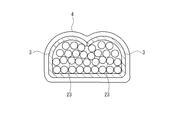
- FIG. 2 is a sectional view taken along line AA in FIG. 1.
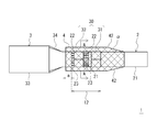
- FIG. 1 is a plan view showing an example of an automobile terminal crimped electric wire according to the present invention
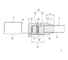
- FIG. 2 is a side view of FIG. 1
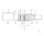
- FIG. 3 is a crevice corrosion between the connection terminal and the resin coating portion of FIG.
- FIG. 4 is a cross-sectional view taken along line AA of FIG. 2, the upper side in FIG. 2 is the upper surface side, the lower side is the bottom surface side, and the upper and lower sides in FIG. 1 are the side surfaces.
- a terminal crimped electric wire for automobiles (hereinafter also referred to as a terminal crimped electric wire) 1 of the present invention has a connection terminal 3 made of a copper-based material crimped to the end of an aluminum electric wire 2. And has a crimping portion 12. Furthermore, a resin-coated portion 4 made of resin is formed on the crimping portion 12 of the terminal crimping electric wire 1.
- FIGS. 1 to 3 show the appearance of the terminal crimped electric wire 1. For convenience of explanation, the region of the resin coating portion 4 is hatched, and each member in the lower layer is seen through the resin coating portion 4. Show.
- the aluminum electric wire 2 includes an insulating covering portion 21 in which a plurality of aluminum conductor wires 23 are covered with an insulator, and a conductor wire portion 22 in which the aluminum conductor wires 23 are exposed by peeling off the terminal insulator.
- connection terminal 3 shown in FIG. 1 and FIG. 2 is one in which tin plating is formed on the surface of a copper alloy.
- the connection terminal 3 is formed into a terminal shape by punching a flat tin-plated copper alloy into a predetermined shape and then bending it with a press. Therefore, the cut surface 34 formed by cutting in the punching process is in a state where it is not tin-plated.
- the connection terminal 3 shown in FIGS. 1 and 2 has an end surface formed as a cut surface 34.
- the connection terminal 3 includes a caulking portion 30 that is crimped to the aluminum electric wire 2 and an electrical contact portion 33 that is connected to another terminal.
- the caulking portion 30 includes a wire barrel 32 for caulking the conductor wire portion 22 of the aluminum electric wire 2, and an insulation barrel 31 for caulking the insulating coating portion 21 of the aluminum electric wire 2 at a predetermined distance from the wire barrel 32.
- the bottom surface of the caulking portion 30 is integrally formed by connecting the insulation barrel portion 31 and the wire barrel portion 32. In the state after the caulking portion 30 of the connection terminal 3 is caulked, a gap is formed between the side surface and the upper surface between the insulation barrel portion 31 and the wire barrel portion 32.
- the electrical contact portion 33 is female and is formed in a box shape into which a male connection terminal (not shown) can be fitted.
- the terminal crimped electric wire 1 has an insulation barrel 31 crimped on the insulation coating portion 21 of the aluminum electric wire 2 and a wire barrel 32 crimped on the conductor wire portion 22 of the aluminum electric wire 2.
- the crimping portion 12 is formed.
- a resin coating portion 4 made of resin is formed on the crimping portion 12 so as to cover the entire periphery of the crimping portion 12.
- an organic resin such as a polyamide resin or a polyolefin resin is used as the material of the resin coating portion 4.
- the “crimping portion 12” is a portion corresponding to the caulking portion 30 in which the insulation barrel 31 and the wire barrel 32 are crimped and crimped to the aluminum electric wire. That is, as shown in FIGS. 1 and 2, this is a portion from the front end of the aluminum conductor wire 23 to the rear end of the insulation barrel 31.
- the longitudinal direction of the terminal crimped electric wire 1 is referred to as the front-rear direction, and the connection side with the other terminals is referred to as the front.
- the “whole circumference” of the crimping portion 12 means the front end portion of the aluminum conductor wire 23 and the outer surface of the barrel of the insulation barrel 31 or the wire barrel 32 in addition to the circumference in the side surface direction of the crimping portion. It is a part including the end surface in the front-rear direction of the barrel (a cut surface cut by punching) and the like. That is, the resin coating portion 4 is formed so as to cover the outer peripheral surface in a long range in the front-rear direction with respect to the crimping portion 12.
- a part of the insulating coating part and a part of the aluminum conductor wire 23 are exposed from the gap between the upper surface and the side surface between the insulation barrel 31 and the wire barrel 32. There are portions that are not covered by the 23 connection terminals. Further, the end of the aluminum conductor wire 23 protrudes from the front end of the wire barrel 32 to the electrical contact portion 33 side. The portions of the aluminum conductor wires 23 that are not covered by the connection terminals are all covered with the resin of the resin coating portion 4 so that the aluminum conductor wires 23 are not exposed to the outside.
- the resin-coated portion 4 made of resin is formed on the crimping portion 12 and the entire periphery of the crimping portion 12 is covered with a resin film, rainwater or the like is prevented from entering the crimping portion 12. Since the resin coating portion 4 is formed so as to cover the outer peripheral surface in a long range before and after the pressure bonding portion 12 and covers the entire periphery of the pressure bonding portion 12, a corrosion factor enters the pressure bonding portion 12 as described later. This can be prevented for a long time. In particular, as shown in FIG. 3, even when the crevice corrosion 41 proceeds in the gap between the connection terminal 3 and the resin coating portion 4, the crevice corrosion 41 does not contact the connection terminal 3 and the aluminum conductor wire 23. Can be prevented for a long time. That is, corrosion of the aluminum conductor wire 23 can be prevented for a long period of time, and the terminal crimped electric wire 1 having stable corrosion resistance can be obtained.
- connection terminal 3 tin corrosion occurs and tin elutes where the resin coating 4 is not formed. Then, the dissimilar metal contact part of tin and copper is exposed. When this copper and tin dissimilar metal contact portion is exposed to water, corrosion of the electrically base tin remarkably proceeds and the corrosion reaches the resin coating portion 4.
- the crevice corrosion 41 proceeds in the gap between the electrical contact portion 33 of the connection terminal 3 and the resin coating portion 4, and the crevice corrosion 41 eventually reaches the dissimilar metal contact portion where the connection terminal 3 and the aluminum conductor wire 23 contact. There is. When the crevice corrosion 41 reaches the dissimilar metal contact portion where the connection terminal 3 and the aluminum conductor wire 23 come into contact with each other, the corrosion of the aluminum conductor wire 23 proceeds remarkably. In particular, since the connection terminal 3 has a dissimilar metal contact portion where the cut surface 34 from which copper is exposed from the beginning and the surface tin contact each other, the influence of corrosion generated from the cut surface 34 is great.
- the resin coating portion 4 has a length a from the tip of the aluminum conductor wire 23 to the tip of the resin coating portion 4 of 0.3 mm or more, more preferably 1.0 mm or more. It is preferable to be formed as described above. When formed in this way, the length from the tip of the aluminum conductor wire to the tip of the resin coating portion becomes sufficiently long, and crevice corrosion that progresses between the resin coating portion 4 and the connection terminal 3 is caused by the aluminum conductor wire. It becomes difficult to reach the dissimilar metal contact part of 23 and the connection terminal 3.
- the resin coating portion 4 is formed so that the thickness of the portion covering the aluminum conductor wire 23 (reference numeral b in FIG. 2) is 0.01 mm or more, the surface of the resin coating portion 4 is scratched. It is easy to prevent the corrosion factor from entering the resin coating 4 and coming into contact with the aluminum conductor wire 23 even when a fine defect occurs. Furthermore, when the resin coating portion 4 is formed so that the thickness of the portion covering the aluminum conductor wire 23 is 0.1 mm or more, even when a larger scratch is applied, the resin coating portion 4 enters the resin coating portion of the corrosion factor. Can be prevented, and corrosion of the automobile terminal crimped electric wire 1 can be more effectively prevented.
- the resin coating portion 4 when the resin coating portion 4 is formed so that the thickness of the portion (reference symbol c in FIG. 2) covering the cut surface of the connection terminal 3 is 0.01 mm or more, the resin coating portion 4 is formed on the surface of the resin coating portion 4. Even when a fine defect such as a scratch occurs, it is easy to prevent a corrosion factor from entering the resin coating portion and coming into contact with the cut surface of the connection terminal 3. Furthermore, if the resin coating portion 4 is formed so that the thickness of the portion covering the cut surface of the connection terminal 3 is 0.1 mm or more, the resin coating of the corrosive factor can be obtained even when there is a larger scratch. The entry into the portion 4 can be prevented, and corrosion of the terminal crimped electric wire 1 can be more effectively prevented.
- the resin coating portion 4 has a taper portion 42 that is gradually tapered toward the aluminum electric wire 2 side at the rear end portion.
- the taper portion 42 is formed on the insulating coating portion 21.
- the resin coating of the resin coating portion 4 is hardly peeled off from the aluminum wire 3 even when the terminal crimped electric wire 1 is bent.
- the corrosion factor can be prevented from entering through the gap between the resin coating portion 4 and the aluminum electric wire 3, and the corrosion resistance of the aluminum conductor wire can be maintained.
- the rising angle ⁇ of the taper portion 42 is 45 ° or less, the resin coating of the resin coating portion 3 can be more effectively prevented from being peeled off from the aluminum electric wire 3.
- the rising angle ⁇ of the taper portion 42 is 30 ° or less, it is possible to prevent the resin film of the resin coating portion from being peeled off from the aluminum electric wire even when the taper portion 42 is bent more repeatedly or repeatedly.
- the resin coating portion 4 is peeled off to the terminal crimping portion even if the resin film of the resin coating portion 4 is somewhat peeled off from the aluminum electric wire 3. This makes it easy to prevent corrosion factors from entering the terminal crimping part. That is, stable anticorrosive properties can be exhibited. If the length is 2 mm or more, it is possible to more effectively prevent the corrosion factor from entering the terminal crimping portion.
- the resin-coated portion 4 can be formed by a method in which a terminal crimped electric wire is put in a suitable mold and the resin is injection-molded, or a molten resin is dripped and formed in a suitable place.
- an appropriate mold is used to control the length from the tip of the aluminum conductor wire to the tip of the resin coating, the thickness of the resin coating, the taper length and the angle of the resin coating. It is possible to use a method such as injection molding by using and using a method, or a method in which a molten resin is dripped in a large amount and solidified and then an excess portion is scraped off.
- Example 1 (Sample Nos. 1 to 16) A 090 female connection terminal is connected to the connection terminal 3 of the terminal crimping electric wire 1, an aluminum electric wire of 0.75 mm 2 or 2.5 mm 2 size is formed on the aluminum electric wire 2, and a polyamide resin (made by Henkel, “ 1), the length a from the tip of the aluminum conductor wire 23 to the tip of the resin coating portion 4 in FIG. 1, the thickness b of the resin coating portion covering the upper side of the conductor wire portion 22, and the terminal Samples 1 to 16 of terminal crimped wires with various thicknesses c of the resin coating on the cut surface were produced, and a corrosion test (JIS C 0023) was performed.
- JIS C 0023 a corrosion test
- the test time is 24 hours, and after taking out from the salt spray device, the presence or absence of corrosion is confirmed by visual observation. This was defined as one cycle, and when there was no corrosion, the test was repeated.
- the results of the corrosion test are shown in Table 1 as the number of cycles in which corrosion occurred.
- Comparative Examples 1 and 2 For comparison, the resin-coated portion was formed only on the conductor wire portion of the crimping portion, but the terminal crimped electric wires of Comparative Examples 1 and 2 were the same as in the above example except that the cut surface was not covered with resin. And a corrosion test was conducted. The results of the corrosion tests of Comparative Examples 1 and 2 are shown in Table 1.
- the resin coating portion 4 covers the entire periphery of the crimping portion 12.
- the terminal crimped electric wires of Examples 1 to 16 formed in the above can withstand a corrosive environment for a long time.
- the crevice corrosion 41 becomes difficult to reach the dissimilar metal contact part of the aluminum conductor wire 23 and the connection terminal 3 by lengthening the length from the front-end
- Example 2 (Sample Nos. 17 to 30) Next, a bending test was performed on the terminal crimped electric wire 1 (No. 29 and 30 did not have a tapered portion) having a tapered portion at the rear end portion of the resin coated portion 4, and the aluminum electric wire 2 and the resin coated portion 4. The difficulty of peeling of the resin film was investigated. The length of the tapered portion is d, and the rising angle of the tapered portion is ⁇ . Hold the part 3cm behind the rear end of the insulation barrel 31 and the electrical contact portion 33 of the connection terminal 3, bend 90 ° in the direction of the crimping surface, and then bend 90 ° in the opposite direction. Then, it was examined whether or not the resin coating of the resin coating portion 4 reaching the insulation barrel 31 was peeled off.
- the presence or absence of peeling of the resin film was confirmed by visual observation.
- the length a from the tip of the aluminum conductor wire 23 to the tip of the resin coating 4 is 1 mm
- the thickness b of the resin coating covering the upper side of the conductor wire 22 was 0.1 mm
- the thickness c of the resin coating on the cut surface of the terminal was 0.1 mm.
Landscapes
- Chemical & Material Sciences (AREA)
- Dispersion Chemistry (AREA)
- Connections Effected By Soldering, Adhesion, Or Permanent Deformation (AREA)
Priority Applications (3)
| Application Number | Priority Date | Filing Date | Title |
|---|---|---|---|
| EP11834117.1A EP2631994B1 (en) | 2010-10-22 | 2011-08-16 | Crimped terminal wire for automobiles |
| US13/877,588 US9246239B2 (en) | 2010-10-22 | 2011-08-16 | Crimped terminal wire for automobile |
| CN2011800509482A CN103181029A (zh) | 2010-10-22 | 2011-08-16 | 机动车用端子压接电线 |
Applications Claiming Priority (2)
| Application Number | Priority Date | Filing Date | Title |
|---|---|---|---|
| JP2010236967A JP2012089431A (ja) | 2010-10-22 | 2010-10-22 | 自動車用端子圧着電線 |
| JP2010-236967 | 2010-10-22 |
Publications (1)
| Publication Number | Publication Date |
|---|---|
| WO2012053275A1 true WO2012053275A1 (ja) | 2012-04-26 |
Family
ID=45975000
Family Applications (1)
| Application Number | Title | Priority Date | Filing Date |
|---|---|---|---|
| PCT/JP2011/068541 Ceased WO2012053275A1 (ja) | 2010-10-22 | 2011-08-16 | 自動車用端子圧着電線 |
Country Status (5)
| Country | Link |
|---|---|
| US (1) | US9246239B2 (enExample) |
| EP (1) | EP2631994B1 (enExample) |
| JP (1) | JP2012089431A (enExample) |
| CN (1) | CN103181029A (enExample) |
| WO (1) | WO2012053275A1 (enExample) |
Cited By (2)
| Publication number | Priority date | Publication date | Assignee | Title |
|---|---|---|---|---|
| CN104488140A (zh) * | 2012-07-25 | 2015-04-01 | 矢崎总业株式会社 | 带端子的电线及使用该电线的线束 |
| WO2022030434A1 (ja) * | 2020-08-05 | 2022-02-10 | 株式会社オートネットワーク技術研究所 | 絶縁電線、ワイヤーハーネス、絶縁電線の製造方法 |
Families Citing this family (22)
| Publication number | Priority date | Publication date | Assignee | Title |
|---|---|---|---|---|
| JP5063750B2 (ja) * | 2010-07-23 | 2012-10-31 | 株式会社オートネットワーク技術研究所 | ワイヤーハーネスの端末構造 |
| JP5409545B2 (ja) * | 2010-08-06 | 2014-02-05 | 住友電装株式会社 | 電線接続部の防食構造 |
| JP5391173B2 (ja) * | 2010-09-30 | 2014-01-15 | 古河電気工業株式会社 | 電線と端子の接続構造及び接続装置、接続方法、ワイヤーハーネス |
| JP2012252900A (ja) * | 2011-06-03 | 2012-12-20 | Yazaki Corp | 接続端子及び接続端子の製造方法 |
| JP5882723B2 (ja) * | 2011-12-26 | 2016-03-09 | 矢崎総業株式会社 | 端子 |
| JP5884986B2 (ja) * | 2012-07-31 | 2016-03-15 | 矢崎総業株式会社 | 圧着端子付きアルミ電線 |
| US9054435B2 (en) * | 2013-07-18 | 2015-06-09 | GM Global Technology Operations LLC | Conversion terminal device and method for coupling dissimilar metal electrical components |
| JP6601995B2 (ja) * | 2013-11-19 | 2019-11-06 | 矢崎総業株式会社 | 端子付き電線 |
| CN103730741B (zh) * | 2014-01-14 | 2016-03-09 | 中国科学院近代物理研究所 | 压接接线端子 |
| FR3033450B1 (fr) * | 2015-03-06 | 2017-02-17 | Delphi Int Operations Luxembourg Sarl | Procede de sertissage d'un contact electrique sur un cable et outil pour la mise en oeuvre de ce procede |
| JP2017195137A (ja) * | 2016-04-22 | 2017-10-26 | 株式会社オートネットワーク技術研究所 | 端子付き被覆電線およびワイヤーハーネス |
| JP6724857B2 (ja) * | 2017-05-11 | 2020-07-15 | 住友電装株式会社 | コネクタ |
| CN107123867B (zh) * | 2017-06-05 | 2019-05-10 | 吉林省中赢高科技有限公司 | 一种铜端子与铝导线的接头及其磁感应焊接方法 |
| JP6825495B2 (ja) * | 2017-06-16 | 2021-02-03 | 株式会社オートネットワーク技術研究所 | 端子付き電線及びワイヤーハーネス |
| CN111194508A (zh) * | 2017-10-25 | 2020-05-22 | 株式会社自动网络技术研究所 | 带端子电线和线束 |
| WO2019082782A1 (ja) * | 2017-10-25 | 2019-05-02 | 株式会社オートネットワーク技術研究所 | 端子付き電線およびワイヤーハーネス |
| JP6856137B2 (ja) * | 2017-10-25 | 2021-04-07 | 株式会社オートネットワーク技術研究所 | 端子付き電線およびワイヤーハーネス |
| JP7052489B2 (ja) * | 2018-03-30 | 2022-04-12 | 株式会社オートネットワーク技術研究所 | 端子付き電線およびワイヤーハーネス |
| JP2019212458A (ja) * | 2018-06-04 | 2019-12-12 | 矢崎総業株式会社 | 端子付き電線および端子付き電線の製造方法 |
| WO2020105153A1 (ja) * | 2018-11-21 | 2020-05-28 | 株式会社オートネットワーク技術研究所 | 端子付き電線 |
| JP7286993B2 (ja) * | 2019-02-14 | 2023-06-06 | 住友電装株式会社 | アース端子およびワイヤーハーネス |
| JP6976989B2 (ja) | 2019-05-21 | 2021-12-08 | 矢崎総業株式会社 | 端子付き電線、塗布装置、および端子付き電線の製造方法 |
Citations (5)
| Publication number | Priority date | Publication date | Assignee | Title |
|---|---|---|---|---|
| JP2001167640A (ja) * | 1999-12-09 | 2001-06-22 | Yazaki Corp | 被覆電線の端末接続部およびその防水処理装置 |
| JP2002315130A (ja) * | 2001-04-09 | 2002-10-25 | Yonezawa Densen Kk | ワイヤハーネス、電線端末の止水構造 |
| JP2010108798A (ja) | 2008-10-31 | 2010-05-13 | Furukawa Electric Co Ltd:The | 異種金属からなる電線と端子の接続部及び接続方法 |
| JP2010108828A (ja) * | 2008-10-31 | 2010-05-13 | Furukawa Electric Co Ltd:The | 導体と端子の接続部および接続方法 |
| JP2010238393A (ja) * | 2009-03-30 | 2010-10-21 | Furukawa Electric Co Ltd:The | 電線と端子の接続部および接続方法 |
Family Cites Families (14)
| Publication number | Priority date | Publication date | Assignee | Title |
|---|---|---|---|---|
| US3143595A (en) * | 1960-12-29 | 1964-08-04 | Thomas & Betts Corp | Polytetrafluoroethylene insulated splice connector |
| US3143545A (en) * | 1961-11-27 | 1964-08-04 | Searle & Co | 4-aminoalkanoyl-2-phenyl-3, 4-dihydro-2h-1, 4-benzothiazines |
| AU531523B2 (en) * | 1978-12-01 | 1983-08-25 | Raychem Gmbh | Electrical apparatus |
| US4304616A (en) * | 1979-04-02 | 1981-12-08 | Raychem Corporation | Radially shrinkable sleeves |
| US5801332A (en) * | 1995-08-31 | 1998-09-01 | Minnesota Mining And Manufacturing Company | Elastically recoverable silicone splice cover |
| JP3701448B2 (ja) * | 1997-10-17 | 2005-09-28 | 株式会社オートネットワーク技術研究所 | 嵌合型接続端子 |
| JP3718394B2 (ja) * | 1999-12-09 | 2005-11-24 | 矢崎総業株式会社 | 被覆電線の端末接続部およびその防水処理方法と装置 |
| JP2003297447A (ja) * | 2002-04-05 | 2003-10-17 | Furukawa Electric Co Ltd:The | 接続端子装置 |
| JP4374187B2 (ja) * | 2002-12-20 | 2009-12-02 | 矢崎総業株式会社 | 端子と被覆電線との接続方法 |
| JP2005050736A (ja) | 2003-07-30 | 2005-02-24 | Furukawa Electric Co Ltd:The | アルミ電線への端子圧着構造及び端子付アルミ電線の製造方法 |
| JP2010165430A (ja) | 2009-01-19 | 2010-07-29 | Alpine Electronics Inc | オーディオ装置 |
| JP2010177134A (ja) * | 2009-01-30 | 2010-08-12 | Sumitomo Wiring Syst Ltd | コネクタ接続部の保護構造 |
| US8360803B2 (en) * | 2009-09-18 | 2013-01-29 | Delphi Technologies, Inc. | Electrical terminal connection with molded seal |
| JP5063751B2 (ja) * | 2010-07-23 | 2012-10-31 | 株式会社オートネットワーク技術研究所 | ワイヤーハーネスの端末構造 |
-
2010
- 2010-10-22 JP JP2010236967A patent/JP2012089431A/ja active Pending
-
2011
- 2011-08-16 CN CN2011800509482A patent/CN103181029A/zh active Pending
- 2011-08-16 EP EP11834117.1A patent/EP2631994B1/en not_active Not-in-force
- 2011-08-16 WO PCT/JP2011/068541 patent/WO2012053275A1/ja not_active Ceased
- 2011-08-16 US US13/877,588 patent/US9246239B2/en not_active Expired - Fee Related
Patent Citations (5)
| Publication number | Priority date | Publication date | Assignee | Title |
|---|---|---|---|---|
| JP2001167640A (ja) * | 1999-12-09 | 2001-06-22 | Yazaki Corp | 被覆電線の端末接続部およびその防水処理装置 |
| JP2002315130A (ja) * | 2001-04-09 | 2002-10-25 | Yonezawa Densen Kk | ワイヤハーネス、電線端末の止水構造 |
| JP2010108798A (ja) | 2008-10-31 | 2010-05-13 | Furukawa Electric Co Ltd:The | 異種金属からなる電線と端子の接続部及び接続方法 |
| JP2010108828A (ja) * | 2008-10-31 | 2010-05-13 | Furukawa Electric Co Ltd:The | 導体と端子の接続部および接続方法 |
| JP2010238393A (ja) * | 2009-03-30 | 2010-10-21 | Furukawa Electric Co Ltd:The | 電線と端子の接続部および接続方法 |
Non-Patent Citations (1)
| Title |
|---|
| See also references of EP2631994A4 |
Cited By (6)
| Publication number | Priority date | Publication date | Assignee | Title |
|---|---|---|---|---|
| CN104488140A (zh) * | 2012-07-25 | 2015-04-01 | 矢崎总业株式会社 | 带端子的电线及使用该电线的线束 |
| CN104488140B (zh) * | 2012-07-25 | 2017-03-08 | 矢崎总业株式会社 | 带端子的电线及使用该电线的线束及其制造方法 |
| WO2022030434A1 (ja) * | 2020-08-05 | 2022-02-10 | 株式会社オートネットワーク技術研究所 | 絶縁電線、ワイヤーハーネス、絶縁電線の製造方法 |
| JP2022029860A (ja) * | 2020-08-05 | 2022-02-18 | 株式会社オートネットワーク技術研究所 | 絶縁電線、ワイヤーハーネス、絶縁電線の製造方法 |
| JP7543765B2 (ja) | 2020-08-05 | 2024-09-03 | 株式会社オートネットワーク技術研究所 | 絶縁電線、ワイヤーハーネス、絶縁電線の製造方法 |
| US12283403B2 (en) | 2020-08-05 | 2025-04-22 | Autonetworks Technologies, Ltd. | Insulated electric wire, wire harness, and insulated electric wire production method |
Also Published As
| Publication number | Publication date |
|---|---|
| US20130199842A1 (en) | 2013-08-08 |
| US9246239B2 (en) | 2016-01-26 |
| JP2012089431A (ja) | 2012-05-10 |
| CN103181029A (zh) | 2013-06-26 |
| EP2631994A1 (en) | 2013-08-28 |
| EP2631994B1 (en) | 2016-09-21 |
| EP2631994A4 (en) | 2014-03-26 |
Similar Documents
| Publication | Publication Date | Title |
|---|---|---|
| WO2012053275A1 (ja) | 自動車用端子圧着電線 | |
| JP6616058B2 (ja) | 端子及び該端子のアルミ電線接続構造 | |
| JP2012174447A (ja) | 自動車用端子圧着電線 | |
| JP5882723B2 (ja) | 端子 | |
| US8641461B2 (en) | Crimp terminal, connection structural body and method for producing the crimp terminal | |
| JP6357334B2 (ja) | 圧着端子と電線の接続構造 | |
| JP5228116B2 (ja) | 接続構造体 | |
| JP4825906B2 (ja) | アルミ電線と銅端子の接続構造およびこの接続構造を有する銅端子付きアルミ電線 | |
| US20110014825A1 (en) | Electrical terminal connection with galvanic sacrificial metal | |
| US20140224536A1 (en) | Electric wire terminal connection structure and intermediary cap used for the same | |
| JP2011181499A (ja) | 接続構造体 | |
| JP2020009639A (ja) | 端子付き電線 | |
| JP5203274B2 (ja) | 電線と端子の接続部および接続方法 | |
| JP2012174449A (ja) | 自動車用端子圧着電線 | |
| JP2012054170A (ja) | 端子圧着電線 | |
| JP2013025910A (ja) | 自動車用端子圧着電線 | |
| US10164350B2 (en) | Terminal attached wire | |
| JP2015210907A (ja) | 端子と該端子の電線接続構造 | |
| US20190036237A1 (en) | Electric wire with terminal | |
| JP6023450B2 (ja) | 端子付き電線 | |
| JP5939865B2 (ja) | 端子付き電線 | |
| JP2013222637A (ja) | 端子付電線 | |
| JP2005108445A (ja) | アルミ電線用接続端子 | |
| JP2013127907A (ja) | 端子付き電線及び連鎖端子 | |
| JP6200165B2 (ja) | 管構造を有したワイヤハーネス用端子 |
Legal Events
| Date | Code | Title | Description |
|---|---|---|---|
| 121 | Ep: the epo has been informed by wipo that ep was designated in this application |
Ref document number: 11834117 Country of ref document: EP Kind code of ref document: A1 |
|
| WWE | Wipo information: entry into national phase |
Ref document number: 13877588 Country of ref document: US |
|
| REEP | Request for entry into the european phase |
Ref document number: 2011834117 Country of ref document: EP |
|
| WWE | Wipo information: entry into national phase |
Ref document number: 2011834117 Country of ref document: EP |
|
| NENP | Non-entry into the national phase |
Ref country code: DE |