WO2012043086A1 - 有機ハイドライド製造装置 - Google Patents
有機ハイドライド製造装置 Download PDFInfo
- Publication number
- WO2012043086A1 WO2012043086A1 PCT/JP2011/068660 JP2011068660W WO2012043086A1 WO 2012043086 A1 WO2012043086 A1 WO 2012043086A1 JP 2011068660 W JP2011068660 W JP 2011068660W WO 2012043086 A1 WO2012043086 A1 WO 2012043086A1
- Authority
- WO
- WIPO (PCT)
- Prior art keywords
- water
- layer
- hydride
- organic hydride
- catalyst layer
- Prior art date
Links
Images
Classifications
-
- C—CHEMISTRY; METALLURGY
- C25—ELECTROLYTIC OR ELECTROPHORETIC PROCESSES; APPARATUS THEREFOR
- C25B—ELECTROLYTIC OR ELECTROPHORETIC PROCESSES FOR THE PRODUCTION OF COMPOUNDS OR NON-METALS; APPARATUS THEREFOR
- C25B3/00—Electrolytic production of organic compounds
-
- C—CHEMISTRY; METALLURGY
- C25—ELECTROLYTIC OR ELECTROPHORETIC PROCESSES; APPARATUS THEREFOR
- C25B—ELECTROLYTIC OR ELECTROPHORETIC PROCESSES FOR THE PRODUCTION OF COMPOUNDS OR NON-METALS; APPARATUS THEREFOR
- C25B3/00—Electrolytic production of organic compounds
- C25B3/20—Processes
- C25B3/25—Reduction
-
- C—CHEMISTRY; METALLURGY
- C25—ELECTROLYTIC OR ELECTROPHORETIC PROCESSES; APPARATUS THEREFOR
- C25B—ELECTROLYTIC OR ELECTROPHORETIC PROCESSES FOR THE PRODUCTION OF COMPOUNDS OR NON-METALS; APPARATUS THEREFOR
- C25B9/00—Cells or assemblies of cells; Constructional parts of cells; Assemblies of constructional parts, e.g. electrode-diaphragm assemblies; Process-related cell features
- C25B9/17—Cells comprising dimensionally-stable non-movable electrodes; Assemblies of constructional parts thereof
- C25B9/19—Cells comprising dimensionally-stable non-movable electrodes; Assemblies of constructional parts thereof with diaphragms
- C25B9/23—Cells comprising dimensionally-stable non-movable electrodes; Assemblies of constructional parts thereof with diaphragms comprising ion-exchange membranes in or on which electrode material is embedded
Definitions
- the present invention relates to an organic hydride production apparatus for electrochemically producing organic hydride.
- Hydrogen fuel has a low environmental impact because it is the only substance that is discharged when fuel is consumed and does not emit carbon dioxide.
- hydrogen is a gas at normal temperature and pressure, transportation, storage, and supply systems are major issues.
- organic hydride systems using hydrocarbons such as cyclohexane, methylcyclohexane, and decalin have attracted attention as hydrogen storage methods that are excellent in safety, transportability, and storage capacity. Since these hydrocarbons are liquid at room temperature, they are excellent in transportability.
- toluene and methylcyclohexane are cyclic hydrocarbons having the same carbon number, but toluene is an unsaturated hydrocarbon in which the bonds between hydrocarbons are double bonds, whereas methylcyclohexane has double bonds. It is a saturated hydrocarbon that does not have.
- Methylcyclohexane is obtained by hydrogenation reaction of toluene, and toluene is obtained by dehydrogenation reaction of methylcyclohexane. That is, hydrogen can be stored and supplied by utilizing the hydrogenation reaction and dehydrogenation reaction of these hydrocarbons.
- the current process is a two-stage process in which hydrogen is generated in a water electrolysis apparatus or the like, and hydrogen and toluene are reacted in a hydrogen addition reaction apparatus to generate organic hydride.
- Patent Document 1 a technique for producing an organic hydride in a single stage using a single apparatus has been disclosed (for example, Patent Document 1). These are for electrochemically producing organic hydrides.
- a metal catalyst is disposed on both sides of a hydrogen ion permeable solid polymer electrolyte membrane that selectively transmits hydrogen ions, water or steam is supplied to one side, and a hydride is supplied to the other side.
- An organic hydride is produced by supplying hydrogen ions generated by electrolysis of water or water vapor on the anode side and a hydride on the cathode side.
- An object of the present invention is to provide a small and efficient organic hydride manufacturing apparatus in an apparatus for electrochemically generating organic hydride.
- the present inventor has formed a layer that blocks permeated water from the anode to the cathode on the surface of the solid polymer electrolyte membrane or in the solid polymer electrolyte membrane. It has been found that a highly efficient electrode can be obtained.
- the catalyst layer has a structure in which a metal catalyst-supporting carbon or a metal catalyst is in a matrix appropriately mixed with a proton conductive solid polymer electrolyte, and the catalyst layer is a permeated water blocking layer. It is formed on the front and back of the formed proton conductive solid polymer electrolyte membrane.
- the cathode catalyst layer for reducing the hydride and the anode catalyst layer for oxidizing water sandwich the proton conductive solid polymer electrolyte membrane in which the permeated water blocking layer is formed.
- a membrane electrode assembly a member for supplying a hydride to the cathode catalyst layer, and a member for supplying water or water vapor to the anode catalyst layer, wherein the cathode catalyst layer reduces the hydride
- a small and efficient organic hydride manufacturing apparatus can be provided in an apparatus for electrochemically generating organic hydride.
- the present invention relates to an apparatus for electrochemically producing organic hydride, wherein a catalyst layer having a structure in which a proton conductive solid polymer electrolyte and a metal catalyst-supporting carbon or a metal catalyst are appropriately mixed is formed into a permeate block. It has the electrode structure formed in the front and back of the proton conductive solid polymer electrolyte membrane in which the layer was formed, It is characterized by the above-mentioned. In this electrode, water or water vapor is supplied to the anode side, and a hydride is supplied to the cathode side, and a voltage is applied between the anode and the cathode, so that water undergoes electrolysis reaction at the anode and hydrogen at the cathode. It is characterized in that an organic hydride is produced by causing a hydrogenation reaction to a compound.
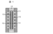
- FIG. 1 shows an example of the organic hydride manufacturing apparatus of the present invention.
- the anode catalyst layer 13 is joined to one surface of the solid polymer electrolyte membrane 12 on which the permeated water blocking layer is formed, and the cathode catalyst layer 14 is joined to the other surface to be integrated.
- a membrane electrode assembly (MEA: Membrane Electrode Assembly) is sandwiched between a pair of gas diffusion layers 15 and a separator 11 in which a gas flow path is formed. Also.
- a gasket 16 for gas sealing is inserted between the pair of separators 11.
- the separator 11 has conductivity, and the material is preferably a dense graphite plate, a carbon plate formed by molding a carbon material such as graphite or carbon black with a resin, or a metal material having excellent corrosion resistance such as stainless steel or titanium. In addition, it is also desirable that the surface of the separator 11 be surface-treated by precious metal plating or applying a conductive paint having excellent corrosion resistance and heat resistance.
- a groove serving as a reaction gas or liquid channel is formed on the surface of the separator 11 facing the anode catalyst layer 13 and the cathode catalyst layer 14. Water or water vapor is supplied to the flow channel of the anode-side separator 11. Water or water vapor flowing through the flow channel is supplied to the anode catalyst layer through the gas diffusion layer 15.
- a hydride is supplied to the side separator 11 on the cathode side.
- the hydride to be flown through the flow channel is supplied to the cathode catalyst through the gas diffusion layer 15.
- a liquid hydride may be supplied as it is, or a vapor hydride using He gas or N 2 gas as a carrier may be supplied.
- the gas diffusion layer 15 is provided to uniformly supply the reactant (gas or liquid) supplied to the flow path of the separator 11 into the surface of the catalyst layer, and has a breathable base such as carbon paper or carbon cloth. Is used. In particular, those obtained by subjecting these substrates to a water repellent treatment are preferable.
- the gasket 16 is insulative, and may be any material that is particularly resistant to hydrogen, hydride, or organic hydride and that has little permeation thereof and can maintain confidentiality.
- a material that is particularly resistant to hydrogen, hydride, or organic hydride and that has little permeation thereof and can maintain confidentiality For example, butyl rubber, viton rubber, EPDM rubber, etc. Can be mentioned.
- the permeated water block is formed in the solid polymer electrolyte membrane, so that the water in the anode does not permeate the cathode. Therefore, organic hydride can be generated with high efficiency.
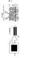
- FIG. 2 shows an electrode portion of the organic hydride manufacturing apparatus of the present embodiment.
- FIG. 2 is a plan view of the MEA in which the cathode catalyst layer 22 and the anode catalyst layer 23 are formed on the front and back of the solid polymer electrolyte membrane 21 in which the permeated water blocking layer 27 is formed, as viewed from the cathode side. A sectional view and an enlarged view of the E portion are shown.
- the cathode and the anode are formed above and below the solid polymer electrolyte membrane 21 on which the permeate blocking layer 27 is formed as a dense catalyst layer.
- a catalyst metal 24 is supported on the catalyst carrier 25, and the catalyst carriers 25 are bonded to each other by a solid polymer electrolyte 26.
- the catalyst metal 24 has a network structure connected to each other through a catalyst carrier 25, and forms a path for electrons necessary for the reaction (2).
- the solid polymer electrolyte 26 in the catalyst layer also has a connected network structure, and forms a passage for protons necessary for the reaction (2).
- the electrode reaction is performed at a three-phase interface where the metal catalyst 24 on the catalyst carrier 25 is in contact with the electrolyte and the reactant.
- the metal catalyst since the passage of protons is formed by the solid polymer electrolyte 26, a three-phase interface is also formed in the metal catalyst 24 not in direct contact with the solid polymer electrolyte membrane 21,
- the metal catalyst has a structure that can contribute to the electrode reaction.
- the permeated water blocking layer 27 is formed on the solid polymer electrolyte membrane, so that the anode water can be prevented from permeating to the cathode. Therefore, organic hydride can be generated with high efficiency.
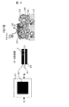
- Fig. 3 shows the structure of a prior art electrode.
- a catalyst carrier 35 carrying a metal catalyst 34 is directly formed on the surface of the solid polymer electrolyte membrane 31.
- the metal catalyst 34 contributing to the electrode reaction is only a portion in direct contact with the electrolyte membrane, and there are few three-phase interfaces, and the catalyst contributing to the reaction is limited.
- the formation of a network structure of the catalyst is small and the resistance is considered to be high.
- Fig. 3 shows the structure of a conventional electrode.
- the electrode shown in FIG. 3 has a structure in which a catalyst carrier 35 supporting a catalyst metal 34 and a solid polymer electrolyte 36 are mixed on the surface of the solid polymer electrolyte membrane 31.
- permeated water 37 in which anode water permeates the solid polymer electrolyte membrane 31 exists in the cathode catalyst layer.
- Water and hydrides such as toluene are insoluble in each other and do not mix. Therefore, when water is present in the cathode catalyst layer 32, the supply of toluene to the catalyst is hindered by the water.
- the MEA of the present invention can be produced by the following method. First, a catalyst catalyst-supported carrier, a solid polymer electrolyte, and a cathode catalyst paste mixed well by adding a solvent for dissolving the solid polymer electrolyte, and the catalyst metal, the solid polymer electrolyte, and the solid polymer electrolyte are dissolved.
- An anode catalyst paste is prepared by adding a solvent and mixing well. Each of these pastes is sprayed on a release film such as a polyfluoroethylene (PTFE) film by a spray drying method or the like, dried at 80 ° C. to evaporate the solvent, and a cathode and an anode catalyst layer are formed.
- a release film such as a polyfluoroethylene (PTFE) film
- the cathode and anode catalyst layers are bonded by a hot press method with the solid polymer electrolyte membrane formed with a permeated water blocking layer in the middle, and the release film (PTFE) is peeled off.
- An MEA can be made.
- the above-mentioned catalyst metal-supported carrier, solid polymer electrolyte, and a cathode catalyst paste in which a solvent for dissolving the solid polymer electrolyte is added and sufficiently mixed Spraying the solid polymer electrolyte and the anode catalyst paste mixed well by adding a solvent that dissolves the solid polymer electrolyte, directly onto the solid polymer electrolyte membrane on which the permeated water blocking layer is formed by spray drying method, etc. But it can be made.
- organic polymers constituting the solid polymer electrolyte membrane include perfluorocarbon sulfonic acid, polystyrene, polyether ketone, polyether ether ketone, polysulfone, polyether sulfone, other engineering plastic materials, sulfonic acid groups, and phosphones.
- a proton donor such as an acid group or a carboxyl group doped or chemically bonded and immobilized can be used. It is also desirable to improve the material stability by forming a crosslinked structure or partially fluorinating the material.
- a composite electrolyte membrane of an organic polymer and a metal oxide hydrate can also be used.
- a layer which blocks permeated water what permeate
- an inorganic substance such as palladium or a palladium alloy
- the metal alloyed with palladium include transition metals such as Rh, Cu, Co, Ir, and Ag.
- Various metals that can be alloyed with Pd such as alkaline earth metals such as Mg and Ca, and rare earth metals such as La and Nd, are conceivable.
- a hydrogen storage alloy is mentioned as a layer which blocks permeated water. Examples of the hydrogen storage alloy include Ti-Fe metal, V metal, Mg alloy, and Ca alloy.
- AB2 type metals based on alloys of transition elements such as Ti, Mn, Zr, and Ni are also included.
- AB5 type based on an alloy containing 5 atoms of a transition element (Ni, Co, Al, etc.) having a catalytic effect on rare earth elements, Nb, and Zr1 atoms such as LaNi 5 and ReNi 5 can be mentioned.
- organic polymers with few proton donors, such as a sulfonic acid group, a phosphonic acid group, and a carboxyl group can also be used.
- an organic polymer having a small proton donor an organic polymer having an ion exchange amount per dry weight of 0.75 meq / g or less is desirable.
- the permeated water blocking layer may be formed on the surface of the solid polymer electrolyte membrane, or may be formed in the solid polymer electrolyte membrane.
- the present invention limits the amount of permeated water by forming a layer that blocks permeated water. Since the permeated water moves with proton movement, the amount thereof varies depending on the value of the flowing current.
- the membrane electrode assembly comprising a permeate blocking layer of the present invention, when the current density value 60 mA / cm 2, which transmission amount of water is below 30 ⁇ g / cm 2 ⁇ sec is desirable.
- the permeated water blocking layer as described above is used so as to satisfy this condition.
- a polymer material exhibiting proton conductivity is used for the solid polymer electrolyte contained in the catalyst layer.
- sulfonation or alkylene sulfonate oxidation represented by perfluorocarbon sulfonic acid resin and polyperfluorostyrene sulfonic acid resin is used. Fluorinated polymers and polystyrenes.
- polysulfones, polyether sulfones, polyether ether sulfones, polyether ether ketones, and materials obtained by introducing a proton donor such as a sulfonic acid group into a hydrocarbon-based polymer can be mentioned.
- the catalyst metal used in the present invention a catalyst material having a hydrogen addition action is used.
- a catalyst material having a hydrogen addition action is used.
- the hydrogenation catalyst is preferably finely divided in order to reduce the cost by reducing the catalyst metal and increase the reaction surface area. Further, in order to prevent a decrease in specific surface area due to aggregation of fine particles, it may be supported on a carrier.
- the method for producing the catalyst is not particularly limited, such as a coprecipitation method, a thermal decomposition method, and an electroless plating method.
- the cathode catalyst support material carbon materials such as activated carbon, carbon nanotubes and graphite, and alumina silicates such as silica, alumina and zeolite can be used.
- a carbon material at the anode is undesirable because it can oxidize the carbon. Therefore, as the anode catalyst support material, a non-carbon material such as alumina silicate such as silica, alumina and zeolite can be used.
- a catalytic metal may be used for the anode without using a supporting material.
- Hydrogen can be stored by adding hydrogen to the double bond between these carbon atoms.
- the solid polymer electrolyte membrane one obtained by physically bonding a 25 ⁇ m palladium membrane to the surface of Nafion (manufactured by DuPont) was used. The palladium membrane was adhered to the anode side surface.
- the cathode catalyst layer was formed by directly applying the catalyst slurry to the solid polymer electrolyte membrane using a spray coater.
- the cathode catalyst layer was applied to the solid polymer electrolyte membrane in the following order.
- the Nafion bonded with the palladium film was placed on the hot plate of the substrate and fixed by suction.
- the temperature of the hot plate was 50 ° C.
- a mask was applied from above, and the cathode catalyst slurry was applied with a spray coater (manufactured by Nordson).
- the coating conditions were a liquid pressure of 0.01 MPa, a swirl pressure of 0.15 MPa, an atomization pressure of 0.15 MPa, a gun / substrate distance of 60 mm, and a substrate temperature of 50 ° C.
- the amount of cathode catalyst was 0.4 mg Pt ⁇ cm ⁇ 2 .
- a cathode catalyst layer was formed on the surface of Nafion to which the palladium film was adhered.
- An anode catalyst layer was formed on the back surface of Nafion.
- the anode catalyst layer was formed by a transfer method.
- an anode catalyst slurry was prepared.
- platinum black HiSPEC1000 manufactured by Johnson Matthey
- 5 wt% Nafion solution 5 wt% Nafion solution
- 221 solution mixed at a weight ratio of 1: 1.11: 2.22 were used. It was applied onto a Teflon (registered trademark) sheet by an applicator.
- An anode catalyst layer coated on a Teflon (registered trademark) sheet was formed on a Nafion surface to which a palladium film was adhered by thermal transfer using a hot press (SA-401-M manufactured by Tester Sangyo Co., Ltd.).
- the hot press pressure was 37.2 kgf ⁇ cm ⁇ 2
- the hot press temperature was 120 ° C.
- the hot press time was 2 minutes.
- the amount of the anode catalyst was 4.8 mg Pt ⁇ cm ⁇ 2 .
- the fabricated MEA was incorporated into the organic hydride manufacturing apparatus shown in FIG.
- the cell resistance was 200 m ⁇ .
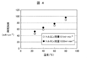
- a voltage of 2.2 V was applied between the anode and the cathode while toluene as a hydride was supplied to the cathode at 0.03 ml / min and 0.1 ml / min, and pure water was supplied to the anode at 5 ml / min.
- the cell temperature was 25, 40, 60, and 80 ° C.
- Fig. 4 shows the current value with respect to the cell temperature.
- the current density increased as the cell temperature increased. This is probably because the higher the temperature, the higher the reaction activity of the electrode catalyst for the reaction.
- the supply amount of toluene was 0.03 ml / min and 0.1 ml / min, almost the same current flowed.
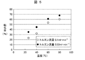
- Fig. 5 shows the conversion rate from toluene to methylcyclohexane during the hydrogenation reaction. The conversion was calculated from the peak area of gas chromatography by the following formula.
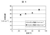
- the fabricated MEA was incorporated into the organic hydride manufacturing apparatus of FIG. 1 and the cell resistance was measured to be 250 m ⁇ .
- Example 2 The hydrogen addition reaction test to toluene was conducted under the same conditions as in Example 1. At a cell temperature of 25, 40, 60, and 80 ° C., a voltage of 2.2 V was applied between the anode and the cathode. FIG. 6 shows the current value with respect to the cell temperature. Although the current flowed as the cell temperature increased, the current density was low in all cases as compared with Example 1.
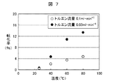
- Fig. 7 shows the conversion rate from toluene to methylcyclohexane.
- S-PES Sulfonated-Poly Ether Sulfone
- S-PES is an organic polymer in which sulfonic acid groups are introduced into polyethersulfone.
- An ion exchange capacity per dry weight of 0.6 meq / g was used.
- Other MEA production conditions were the same as in Example 1.
- the fabricated MEA was incorporated into the organic hydride manufacturing apparatus of FIG. 1 and the cell resistance was measured to be 350 m ⁇ . Under the same conditions as in Example 1, a hydrogen addition reaction test with toluene was performed. At a cell temperature of 25, 40, 60, and 80 ° C., a voltage of 2.2 V was applied between the anode and the cathode.
Landscapes
- Chemical & Material Sciences (AREA)
- Organic Chemistry (AREA)
- Engineering & Computer Science (AREA)
- Chemical Kinetics & Catalysis (AREA)
- Electrochemistry (AREA)
- Materials Engineering (AREA)
- Metallurgy (AREA)
- Electrolytic Production Of Non-Metals, Compounds, Apparatuses Therefor (AREA)
- Electrodes For Compound Or Non-Metal Manufacture (AREA)
Abstract
Description
C7H8+6H++6e-→C7H14 (2)
本実施形態の有機ハイドライド装置では、固体高分子電解質膜に透過水ブロックが形成されているため、アノードの水がカソードに透過することはない。よって、高効率で有機ハイドライドの生成が可能である。
よって、従来技術の電極では、被水素化物への水素付加反応が起こらない触媒が存在するため有機ハイドライド生成が制限され、その結果、エネルギー効率が低くなってしまうと考えられる。
セル温度25℃,40℃,60℃,80℃いずれにおいてもメチルシクロヘキサンは検出され、セル温度が高くなるほど転化率は大きくなった。また、トルエンの供給量0.1ml/minに比べて、0.03ml/minの方が転化率は高い結果となった。これは、トルエンの供給速度が小さいほど、トルエンが電極触媒に接する機会が増えたためであると考えられる。今回の条件で最も転化率が高かったのは、セル温度80℃トルエン流量0.03ml/minにおいて、転化率68%であった。
〔比較例1〕
固体高分子電解質膜として、ナフィオンを用いてMEAを作製した。その他の作製条件は同一とした。
Claims (12)
- 有機ハイドライド製造装置であって、
被水素化物を還元するカソード触媒層、および水を酸化するアノード触媒層がプロトン導電性の固体高分子電解質膜を挟むように配置された膜電極接合体と、前記カソード触媒層に被水素化物を供給する部材と、前記アノード触媒層に水または水蒸気を供給する部材とを備え、
前記固体高分子電解質膜の表面もしくは内部に、水をブロックする層が形成されていることを特徴とする有機ハイドライド製造装置。 - 請求項1において、前記水をブロックする層が、パラジウムもしくはパラジウム合金であることを特徴とする有機ハイドライド製造装置。
- 請求項1において、前記水をブロックする層が、乾燥重量当たりのイオン交換量が0.75meq/g以下の有機高分子であることを特徴とする有機ハイドライド製造装置。
- 請求項1において、前記カソード触媒層が、触媒金属と、前記触媒金属を担持した担体からなり、
前記アノード触媒層が、触媒金属のみ、もしくは、触媒金属と前記触媒金属を担持した非カーボン担体からなることを特徴とする有機ハイドライド製造装置。 - 請求項1において、前記被水素化物が、ベンゼン,トルエン,キシレン,メシチレン,ナフタレン,メチルナフタレン、または、アントラセンであることを特徴とする有機ハイドライド製造装置。
- 請求項1において、前記カソード触媒層が、触媒金属と、前記触媒金属を担持した担体からなり、前記触媒金属が、白金,ルテニウム,ロジウム,パラジウム,イリジウム,モリブデン,レニウム,タングステンおよびこれらの少なくとも一部を含む合金からなることを特徴とする有機ハイドライド製造装置。
- 被水素化物を還元するカソード触媒層、および水を酸化するアノード触媒層がプロトン導電性の固体高分子電解質膜を挟むように配置された膜電極接合体と、前記カソード触媒層および前記アノード触媒層の表面に配置されたガス拡散層と、前記ガス拡散層の表面に配置され、前記ガス拡散層と接する面に流路溝が形成されたセパレータとを備える有機ハイドライド製造装置であって、
前記固体高分子電解質膜表面もしくは内部に、水をブロックする層が形成されていることを特徴とする有機ハイドライド製造装置。 - 請求項7において、前記水をブロックする層が、パラジウムもしくはパラジウム合金であることを特徴とする有機ハイドライド製造装置。
- 請求項7において、前記水をブロックする層が、乾燥重量当たりのイオン交換量が0.75meq/g以下の有機高分子であることを特徴とする有機ハイドライド製造装置。
- 請求項7において、前記カソード触媒層側のセパレータの流路溝に被水素化物が供給され、前記アノード触媒層側のセパレータの流路溝に水または水蒸気が供給されることを特徴とする有機ハイドライド製造装置。
- 請求項7において、前記被水素化物が、ベンゼン,トルエン,キシレン,メシチレン,ナフタレン,メチルナフタレン、または、アントラセンであることを特徴とする有機ハイドライド製造装置。
- 請求項7において、前記カソード触媒層が、触媒金属と、前記触媒金属を担持した担体からなり、前記触媒金属が、白金,ルテニウム,ロジウム,パラジウム,イリジウム,モリブデン,レニウム,タングステンおよびこれらの少なくとも一部を含む合金からなることを特徴とする有機ハイドライド製造装置。
Priority Applications (2)
| Application Number | Priority Date | Filing Date | Title |
|---|---|---|---|
| US13/817,333 US20140144774A1 (en) | 2010-09-30 | 2011-08-18 | Device for manufacturing organic hydride |
| CN2011800400333A CN103069051A (zh) | 2010-09-30 | 2011-08-18 | 有机氢化物制造装置 |
Applications Claiming Priority (2)
| Application Number | Priority Date | Filing Date | Title |
|---|---|---|---|
| JP2010-220254 | 2010-09-30 | ||
| JP2010220254A JP2012072477A (ja) | 2010-09-30 | 2010-09-30 | 有機ハイドライド製造装置 |
Publications (1)
| Publication Number | Publication Date |
|---|---|
| WO2012043086A1 true WO2012043086A1 (ja) | 2012-04-05 |
Family
ID=45892561
Family Applications (1)
| Application Number | Title | Priority Date | Filing Date |
|---|---|---|---|
| PCT/JP2011/068660 WO2012043086A1 (ja) | 2010-09-30 | 2011-08-18 | 有機ハイドライド製造装置 |
Country Status (4)
| Country | Link |
|---|---|
| US (1) | US20140144774A1 (ja) |
| JP (1) | JP2012072477A (ja) |
| CN (1) | CN103069051A (ja) |
| WO (1) | WO2012043086A1 (ja) |
Cited By (5)
| Publication number | Priority date | Publication date | Assignee | Title |
|---|---|---|---|---|
| EP2980276A4 (en) * | 2013-03-29 | 2016-11-02 | Jx Nippon Oil & Energy Corp | ELECTROCHEMICAL REDUCING DEVICE AND METHOD FOR PRODUCING A HYDROGENATED PRODUCT OF AN AROMATIC COMPOUND |
| EP2985365A4 (en) * | 2013-03-29 | 2016-11-02 | Jx Nippon Oil & Energy Corp | ELECTROCHEMICAL REDUCING DEVICE AND METHOD FOR PRODUCING A HYDROGENATED PRODUCT OF AN AROMATIC COMPOUND |
| EP3040449A4 (en) * | 2013-08-30 | 2017-03-01 | JX Nippon Oil & Energy Corporation | Electrochemical reduction device |
| JP2019011492A (ja) * | 2017-06-29 | 2019-01-24 | 富士通株式会社 | 二酸化炭素還元膜、及びその製造方法、並びに二酸化炭素還元装置 |
| CN113135614A (zh) * | 2021-03-10 | 2021-07-20 | 中国工程物理研究院材料研究所 | 一种基于质子交换膜的有机污染物阳极氧化处理装置 |
Families Citing this family (11)
| Publication number | Priority date | Publication date | Assignee | Title |
|---|---|---|---|---|
| JP2013084360A (ja) * | 2011-10-06 | 2013-05-09 | Hitachi Ltd | 膜電極接合体及び有機ハイドライド製造装置 |
| FR3009834B1 (fr) * | 2013-08-23 | 2015-08-28 | Commissariat Energie Atomique | Assemblage couche active/membrane pour dispositif de production d'hydrogene et ensemble comprenant ledit assemblage adapte a un collecteur de courant poreux et procede de fabrication de l'assemblage |
| US10202698B2 (en) | 2014-03-28 | 2019-02-12 | Yokohama National University | Device for manufacturing organic hydride |
| JP6400410B2 (ja) * | 2014-09-25 | 2018-10-03 | 国立大学法人横浜国立大学 | 有機ケミカルハイドライド製造用電解セル |
| CA2966834C (en) * | 2014-11-10 | 2022-08-30 | National University Corporation Yokohama National University | Oxygen-generating anode |
| JP6501141B2 (ja) | 2014-11-21 | 2019-04-17 | 国立大学法人横浜国立大学 | 有機ハイドライド製造装置およびこれを用いた有機ハイドライドの製造方法 |
| KR101773969B1 (ko) * | 2016-11-11 | 2017-09-04 | 한국과학기술연구원 | 환원반응을 향상시키는 전기화학 반응 셀 |
| JP6758628B2 (ja) * | 2016-11-15 | 2020-09-23 | 国立大学法人横浜国立大学 | 有機ハイドライド製造装置及び有機ハイドライドの製造方法 |
| JP7115728B2 (ja) * | 2017-02-03 | 2022-08-09 | 国立大学法人 東京大学 | 膜電極接合体 |
| CN107913653B (zh) * | 2017-12-26 | 2023-08-15 | 大连理工大学盘锦产业技术研究院 | 一种电化学加氢装置及方法 |
| JPWO2022118695A1 (ja) * | 2020-12-03 | 2022-06-09 |
Citations (5)
| Publication number | Priority date | Publication date | Assignee | Title |
|---|---|---|---|---|
| JPS5789488A (en) * | 1980-11-25 | 1982-06-03 | Tokuyama Soda Co Ltd | Electrolysis of organic compound |
| JPH02262543A (ja) * | 1988-02-29 | 1990-10-25 | Nippon Shokubai Kagaku Kogyo Co Ltd | 1―アミノアントラキノン類の製造法 |
| JPH10195686A (ja) * | 1997-01-07 | 1998-07-28 | Permelec Electrode Ltd | 水素化方法及び電解槽 |
| JP2003045449A (ja) * | 2001-08-01 | 2003-02-14 | Masaru Ichikawa | 化学発電/有機ハイドライド製造装置および化学発電/有機ハイドライド製造方法 |
| JP2009007647A (ja) * | 2007-06-29 | 2009-01-15 | Hitachi Ltd | 有機ハイドライド製造装置、及び、それを用いた分散電源と自動車 |
Family Cites Families (4)
| Publication number | Priority date | Publication date | Assignee | Title |
|---|---|---|---|---|
| JP4223619B2 (ja) * | 1999-02-15 | 2009-02-12 | ペルメレック電極株式会社 | 電解用陰極及びこの陰極を具備した電解槽 |
| US6949178B2 (en) * | 2002-07-09 | 2005-09-27 | Lynntech, Inc. | Electrochemical method for preparing peroxy acids |
| JP2006049110A (ja) * | 2004-08-05 | 2006-02-16 | Hitachi Ltd | 燃料電池用触媒、それを用いた膜電極接合体、その製造方法及び燃料電池 |
| WO2006028190A1 (ja) * | 2004-09-09 | 2006-03-16 | Asahi Kasei Chemicals Corporation | 固体高分子電解質膜およびその製造方法 |
-
2010
- 2010-09-30 JP JP2010220254A patent/JP2012072477A/ja active Pending
-
2011
- 2011-08-18 CN CN2011800400333A patent/CN103069051A/zh active Pending
- 2011-08-18 WO PCT/JP2011/068660 patent/WO2012043086A1/ja active Application Filing
- 2011-08-18 US US13/817,333 patent/US20140144774A1/en not_active Abandoned
Patent Citations (5)
| Publication number | Priority date | Publication date | Assignee | Title |
|---|---|---|---|---|
| JPS5789488A (en) * | 1980-11-25 | 1982-06-03 | Tokuyama Soda Co Ltd | Electrolysis of organic compound |
| JPH02262543A (ja) * | 1988-02-29 | 1990-10-25 | Nippon Shokubai Kagaku Kogyo Co Ltd | 1―アミノアントラキノン類の製造法 |
| JPH10195686A (ja) * | 1997-01-07 | 1998-07-28 | Permelec Electrode Ltd | 水素化方法及び電解槽 |
| JP2003045449A (ja) * | 2001-08-01 | 2003-02-14 | Masaru Ichikawa | 化学発電/有機ハイドライド製造装置および化学発電/有機ハイドライド製造方法 |
| JP2009007647A (ja) * | 2007-06-29 | 2009-01-15 | Hitachi Ltd | 有機ハイドライド製造装置、及び、それを用いた分散電源と自動車 |
Cited By (6)
| Publication number | Priority date | Publication date | Assignee | Title |
|---|---|---|---|---|
| EP2980276A4 (en) * | 2013-03-29 | 2016-11-02 | Jx Nippon Oil & Energy Corp | ELECTROCHEMICAL REDUCING DEVICE AND METHOD FOR PRODUCING A HYDROGENATED PRODUCT OF AN AROMATIC COMPOUND |
| EP2985365A4 (en) * | 2013-03-29 | 2016-11-02 | Jx Nippon Oil & Energy Corp | ELECTROCHEMICAL REDUCING DEVICE AND METHOD FOR PRODUCING A HYDROGENATED PRODUCT OF AN AROMATIC COMPOUND |
| US10815575B2 (en) | 2013-03-29 | 2020-10-27 | Eneos Corporation | Electrochemical reduction device and method for manufacturing hydride of aromatic compound |
| EP3040449A4 (en) * | 2013-08-30 | 2017-03-01 | JX Nippon Oil & Energy Corporation | Electrochemical reduction device |
| JP2019011492A (ja) * | 2017-06-29 | 2019-01-24 | 富士通株式会社 | 二酸化炭素還元膜、及びその製造方法、並びに二酸化炭素還元装置 |
| CN113135614A (zh) * | 2021-03-10 | 2021-07-20 | 中国工程物理研究院材料研究所 | 一种基于质子交换膜的有机污染物阳极氧化处理装置 |
Also Published As
| Publication number | Publication date |
|---|---|
| CN103069051A (zh) | 2013-04-24 |
| JP2012072477A (ja) | 2012-04-12 |
| US20140144774A1 (en) | 2014-05-29 |
Similar Documents
| Publication | Publication Date | Title |
|---|---|---|
| WO2012043086A1 (ja) | 有機ハイドライド製造装置 | |
| JP5705214B2 (ja) | 有機ハイドライド製造装置 | |
| KR101417354B1 (ko) | 막 전극 접합체 및 유기 하이드라이드 제조 장치 | |
| JP6685961B2 (ja) | 水電解用の積層電解質膜、膜電極複合体、水電解用セル、スタックおよび水電解装置 | |
| AU2009246798B2 (en) | Permselective membrane-free direct fuel cell and components thereof | |
| JP5831913B2 (ja) | 有機化合物の水素化装置及び水素化方法 | |
| US8017274B2 (en) | Fuel cell | |
| WO2018037774A1 (ja) | カソード、有機ハイドライド製造用電解セル及び有機ハイドライドの製造方法 | |
| CN101809791A (zh) | 燃料电池体系 | |
| WO2018216356A1 (ja) | 有機ハイドライド製造装置 | |
| JP4438525B2 (ja) | 燃料電池用セルモジュール及びその製造方法、並びに燃料電池 | |
| WO2014192089A1 (ja) | 有機ハイドライド製造装置 | |
| JP6998797B2 (ja) | 有機ハイドライド製造装置、有機ハイドライドの製造方法およびエネルギー輸送方法 | |
| JP2001076742A (ja) | 固体高分子型燃料電池 | |
| KR20190125885A (ko) | 전기화학적 탈수소화 반응기 및 이것을 이용한 수소의 제조방법 | |
| WO2022091361A1 (ja) | 有機ハイドライド製造装置およびカソード触媒層の形成方法 | |
| WO2024048340A1 (ja) | 有機ハイドライド製造装置および有機ハイドライド製造方法 | |
| WO2022091360A1 (ja) | 有機ハイドライド製造装置 | |
| WO2024034444A1 (ja) | 有機ハイドライド製造装置 |
Legal Events
| Date | Code | Title | Description |
|---|---|---|---|
| WWE | Wipo information: entry into national phase |
Ref document number: 201180040033.3 Country of ref document: CN |
|
| 121 | Ep: the epo has been informed by wipo that ep was designated in this application |
Ref document number: 11828647 Country of ref document: EP Kind code of ref document: A1 |
|
| NENP | Non-entry into the national phase |
Ref country code: DE |
|
| WWE | Wipo information: entry into national phase |
Ref document number: 13817333 Country of ref document: US |
|
| 122 | Ep: pct application non-entry in european phase |
Ref document number: 11828647 Country of ref document: EP Kind code of ref document: A1 |