WO2012029543A1 - 遠心圧縮機のディフューザおよびこれを備えた遠心圧縮機 - Google Patents
遠心圧縮機のディフューザおよびこれを備えた遠心圧縮機 Download PDFInfo
- Publication number
- WO2012029543A1 WO2012029543A1 PCT/JP2011/068611 JP2011068611W WO2012029543A1 WO 2012029543 A1 WO2012029543 A1 WO 2012029543A1 JP 2011068611 W JP2011068611 W JP 2011068611W WO 2012029543 A1 WO2012029543 A1 WO 2012029543A1
- Authority
- WO
- WIPO (PCT)
- Prior art keywords
- blade
- wing
- shroud
- hub
- diffuser
- Prior art date
Links
Images


Classifications
-
- F—MECHANICAL ENGINEERING; LIGHTING; HEATING; WEAPONS; BLASTING
- F04—POSITIVE - DISPLACEMENT MACHINES FOR LIQUIDS; PUMPS FOR LIQUIDS OR ELASTIC FLUIDS
- F04D—NON-POSITIVE-DISPLACEMENT PUMPS
- F04D29/00—Details, component parts, or accessories
- F04D29/40—Casings; Connections of working fluid
- F04D29/42—Casings; Connections of working fluid for radial or helico-centrifugal pumps
- F04D29/44—Fluid-guiding means, e.g. diffusers
-
- F—MECHANICAL ENGINEERING; LIGHTING; HEATING; WEAPONS; BLASTING
- F04—POSITIVE - DISPLACEMENT MACHINES FOR LIQUIDS; PUMPS FOR LIQUIDS OR ELASTIC FLUIDS
- F04D—NON-POSITIVE-DISPLACEMENT PUMPS
- F04D17/00—Radial-flow pumps, e.g. centrifugal pumps; Helico-centrifugal pumps
- F04D17/08—Centrifugal pumps
- F04D17/10—Centrifugal pumps for compressing or evacuating
-
- F—MECHANICAL ENGINEERING; LIGHTING; HEATING; WEAPONS; BLASTING
- F04—POSITIVE - DISPLACEMENT MACHINES FOR LIQUIDS; PUMPS FOR LIQUIDS OR ELASTIC FLUIDS
- F04D—NON-POSITIVE-DISPLACEMENT PUMPS
- F04D29/00—Details, component parts, or accessories
- F04D29/40—Casings; Connections of working fluid
- F04D29/42—Casings; Connections of working fluid for radial or helico-centrifugal pumps
- F04D29/44—Fluid-guiding means, e.g. diffusers
- F04D29/441—Fluid-guiding means, e.g. diffusers especially adapted for elastic fluid pumps
- F04D29/444—Bladed diffusers
-
- F—MECHANICAL ENGINEERING; LIGHTING; HEATING; WEAPONS; BLASTING
- F04—POSITIVE - DISPLACEMENT MACHINES FOR LIQUIDS; PUMPS FOR LIQUIDS OR ELASTIC FLUIDS
- F04D—NON-POSITIVE-DISPLACEMENT PUMPS
- F04D29/00—Details, component parts, or accessories
- F04D29/66—Combating cavitation, whirls, noise, vibration or the like; Balancing
- F04D29/68—Combating cavitation, whirls, noise, vibration or the like; Balancing by influencing boundary layers
- F04D29/681—Combating cavitation, whirls, noise, vibration or the like; Balancing by influencing boundary layers especially adapted for elastic fluid pumps
-
- F—MECHANICAL ENGINEERING; LIGHTING; HEATING; WEAPONS; BLASTING
- F05—INDEXING SCHEMES RELATING TO ENGINES OR PUMPS IN VARIOUS SUBCLASSES OF CLASSES F01-F04
- F05D—INDEXING SCHEME FOR ASPECTS RELATING TO NON-POSITIVE-DISPLACEMENT MACHINES OR ENGINES, GAS-TURBINES OR JET-PROPULSION PLANTS
- F05D2250/00—Geometry
- F05D2250/50—Inlet or outlet
- F05D2250/52—Outlet
-
- F—MECHANICAL ENGINEERING; LIGHTING; HEATING; WEAPONS; BLASTING
- F05—INDEXING SCHEMES RELATING TO ENGINES OR PUMPS IN VARIOUS SUBCLASSES OF CLASSES F01-F04
- F05D—INDEXING SCHEME FOR ASPECTS RELATING TO NON-POSITIVE-DISPLACEMENT MACHINES OR ENGINES, GAS-TURBINES OR JET-PROPULSION PLANTS
- F05D2250/00—Geometry
- F05D2250/70—Shape
Definitions
- the present invention relates to a diffuser and a centrifugal compressor equipped with the diffuser, and particularly to a diffuser in which blades having different inlet angles are combined in the blade height direction.
- FIG. 14 shows a main part of the centrifugal compressor of Patent Document 1.
- 14A is a longitudinal sectional view
- FIG. 14B is a side view
- FIG. 14C is an enlarged perspective view of the shroud side wing and the hub side wing
- FIG. 14D is FIG. It is a top view of (C).
- the centrifugal compressor 50 shown in FIG. 14 compresses a fluid such as gas or air introduced from the outside of the housing 51 by rotating an impeller 53 having a large number of blades 52 in the housing 51.
- the fluid flow (airflow) formed in this way is sent to the outside through an impeller outlet (hereinafter also referred to as “diffuser inlet”) 54, a diffuser 55, and a volute 56, which is an outer peripheral end of the impeller 53.
- symbol 57 in a figure is an axial centerline with which the impeller 53 rotates.
- the diffuser 55 described above is an airflow passage provided between the impeller outlet 54 and the volute 56, and has a function of restoring dynamic pressure to static pressure by decelerating the airflow discharged from the impeller outlet 54. ing.
- the diffuser 55 is usually formed of a pair of opposed wall surfaces. In the following description, one of the pair of opposed wall surfaces is referred to as a shroud side wall surface 58 and the other is referred to as a hub side wall surface 2.
- the diffuser 51 is provided with a plurality of diffuser blades 60 between the shroud side wall surface 58 and the hub side wall surface 2.
- the diffuser blade 60 includes a plurality of shroud side blades 3 provided on the shroud side wall surface 58 and a plurality of hub side blades 4 provided on the hub side wall surface 2.
- the shroud side wing 3 and the hub side wing 4 are obtained by combining two-dimensional wings having different blade inlet angles in the blade height direction.
- the shroud side blade 3 and the hub side blade 4 having different blade inlet angles are combined, and the flow angle of the airflow at the blade 52 exit (the angle formed by the streamline of the airflow and the cascade line) becomes the inlet angle of the diffuser blade 60.
- the efficiency of the diffuser 55 can be increased and the operating range can be expanded.
- the present invention has been made in view of such circumstances, and a centrifugal compressor diffuser capable of improving performance by combining blades having different inlet angles in the blade height direction, and a centrifugal equipped with the same
- An object is to provide a compressor.
- the diffuser of the centrifugal compressor according to the first aspect of the present invention includes a shroud side wall surface provided on the downstream side of the centrifugal impeller, a hub side wall surface provided to face the shroud side wall surface, and the shroud side wall surface.
- a plurality of shroud side wings to which the base end portion is fixed and a plurality of hub side wings to which the base end portion is fixed to the hub side wall surface, and the inlet angle of the shroud side wing and the hub side wing is different.
- a diffuser of a centrifugal compressor having a shroud side blade and a hub side blade combined with each other having different inlet angles and at least a portion of the tip in the blade height direction being in contact with each other includes a tip of the combined shroud blade There may be a gap in which the front end of the hub side wing is not abutted. As described above, when a gap is formed in which the tip portions of the shroud side blade and the hub side blade are not abutted with each other, the performance of the diffuser deteriorates due to separation of a flow passing through the gap portion and generation of vortices.
- a connecting member for connecting the tip portions of the shroud side wing and the hub side wing is provided so as to fill at least a part of the gap formed without the butts of the tip ends of the combined shroud side wing and hub side wing.
- the shape of the connection member is continuously connected in the circumferential direction between the tip portions of the plurality of shroud side blades and the plurality of hub side blades. It is good also as an annular shape.
- the connecting member may continuously connect all the tip portions of the shroud side blade and the hub side wall blade in an annular shape. Therefore, the gap between the tip of the shroud wing and the tip of the hub wing when combined can be covered by the connecting member, and the gap flow can be eliminated. Thereby, generation
- the annular connecting member may have an inner diameter smaller than inner diameters of the shroud side wall surface and the hub side wall surface.
- the inner diameter of the annular connection member is smaller than the inner diameters of the shroud side wall surface and the hub side wall surface, the inner diameter of the annular connection member is reduced to the shroud side wall surface and the hub.
- the inner diameter of the side wall surface is the same, it is possible to improve the performance of the diffuser by eliminating the flow that passes through the gap generated between the tip of the shroud blade and the tip of the hub blade when combined. I found it possible.
- the connecting member includes 60% of the blade length from the leading edge of at least one of the distal end portion of the shroud side blade or the distal end portion of the hub side blade. It is good also as what connects so that a downstream may be filled.
- the connecting member was connected in the circumferential direction so as to fill a gap between the leading edge of the tip of at least one shroud side blade or the hub side blade and 60% downstream of the blade length. Therefore, similarly to the case where the connecting member is connected in the circumferential direction so as to fill the gap over the entire blade length from the leading edge to the trailing edge, it is possible to suppress flow separation and vortex generation due to the gap flow. Therefore, the performance of the diffuser can be improved.
- the shroud side wing and the hub side wing to be combined may be arranged with their leading edges shifted in the circumferential direction.
- the shroud side blades and the hub side blades to be combined are shifted in the circumferential direction so that 60% of the total length from the leading edge does not overlap. May be arranged.
- the shroud side wing and the hub side wing combined with the shroud side wing may be provided so as to be shifted in the circumferential direction so as not to overlap each other up to 60% of the total length from the leading edge. Therefore, there is no gap between the front edge of the shroud side wing and the hub side wing and 60% of the total length. Accordingly, it is possible to improve the performance of the diffuser by suppressing separation and vortex generation due to the gap flow.
- the shroud side wall surface provided on the downstream side of the centrifugal impeller, the hub side wall surface provided to face the shroud side wall surface, and the shroud side A plurality of shroud side blades whose base end portions are fixed to the wall surface and a plurality of hub side blades whose base end portions are fixed to the hub side wall surface, and the shroud side blades and the hub side blades have different entrance angles.
- the tip portions in the blade height direction are combined in a state where they are abutted so that part of the blade thickness overlaps each other over the blade length.
- the shroud-side wing and the hub-side wing have different inlet angles, and the tip portions in the blade height direction are abutted so that part of the blade thickness overlaps the blade length. Therefore, when the shroud side wing and the hub side wing are combined, no gap is generated between the tip portion of the shroud side wing and the tip portion of the hub side wing. Therefore, it is possible to prevent flow separation and vortex generation due to the gap flow, and to improve the performance of the diffuser. Further, since the tip portions in the blade height direction of the shroud side wing and the hub side wing are brought together so that part of the blade thickness overlaps each other over the blade length, the rigidity of the blade can be increased. Therefore, the vibration strength of the blade can be improved.
- the blade thickness of each trailing edge of the shroud side blade and the hub side blade may be made thinner than the blade thickness at the center of the blade length.
- each trailing edge of the shroud side wing and hub side wing may be made thinner than the blade thickness at the center of the blade length. Therefore, the wake of the shroud side wing and the hub side wing can be reduced. Therefore, the performance of the diffuser can be improved.
- either the shroud side wing or the hub side wing may be a thick wing and the other may be a thin wing.
- One of the shroud side wing and the hub side wing may be a thick wing (for example, a cross-sectional shape perpendicular to the blade height direction is a wedge type or a channel type), and the other may be a thin wing.
- blade the width of the cross-sectional shape orthogonal to a wing
- a centrifugal compressor according to the third aspect of the present invention includes the diffuser for a centrifugal compressor described above.
- the connecting member that connects the tip portions of the shroud side blades and the hub side blades connected to each other so as to fill at least a part of the gap formed without being abutted. It was decided to provide. Thereby, the clearance gap produced between the front-end
- FIG. 1 It is a top view of the modification 2 of the wing
- FIG. 8 is a modification of the wing shown in FIG. 8, (A) is a perspective view thereof, and (B) is a top view of (A). It is the shroud side blade
- FIG. 10 is a modification of the wing shown in FIG.
- FIG. 10 is a modification of the wing shown in FIG. 12, (A) is a perspective view thereof, and (B) is a top view of (A).
- the principal part of the conventional centrifugal compressor is shown, (A) is a longitudinal sectional view, (B) is a side view, and (C) is an enlarged perspective view of a shroud side blade and a hub side blade.
- D) is a top view of (C).
- FIG. 1 decelerates the airflow (flow) discharged from the outer peripheral end of the impeller 53 (see FIG. 14) rotating in the housing 51 (see FIG. 14) of the centrifugal compressor 50 (see FIG. 14).
- the dynamic pressure of the airflow is restored to static pressure.
- the diffuser 1 includes a shroud side wall surface 58 provided on the downstream side of the impeller (centrifugal impeller) 53, a hub side wall surface 2 provided to face the shroud side wall surface 58, and a base end portion on the shroud side wall surface 58.
- a plurality of shroud side blades 3 (only one blade is shown in FIG. 1) and a plurality of blades whose base end is fixed to the hub side wall surface 2 (only one blade is shown in FIG. 1). .) Hub side wing 4.
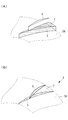
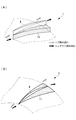
- the shroud side wing 3 and the hub side wing 4 are two-dimensional wings, and are thin wings having the same wing length.
- the shroud side wing 3 and the hub side wing 4 are combined such that the entrance angles are different and the leading edges (at least a part) of the tip in the blade height direction are abutted with each other. In addition, their trailing edges are separated in the circumferential direction.
- connection wall 5 is provided.
- the connection wall 5 is provided along the entire length from the front edge to the rear edge of the shroud side wing 3 and the hub side wing 4.
- connection wall 5 is provided in the gap 63 between the shroud-side wing 3 and the hub-side wing 4, so that the airflow guided from the front edge of the shroud-side wing 3 is the upper surface of the connection wall 5 (above FIG. 1A). ) Flow along. Therefore, it is possible to suppress the separation of airflow and the generation of vortices due to the gap flow.
- the diffuser 1 of the centrifugal compressor according to the first embodiment and the centrifugal compressor provided with the same have the following effects.
- the tip portions of the shroud side blade 3 and the hub side blade 4 are connected to each other so as to fill a gap 63 (see FIG. 14) generated without the tips of the shroud side blade 3 and the hub side blade 4 being combined.
- a connecting wall (connecting member) 5 is provided.
- a gap 63 formed between the tip of the shroud side blade 3 and the tip of the hub side wall blade 4 is covered by the connection wall 5. Therefore, the gap flow can be eliminated, and flow separation and vortex generation due to the gap flow can be suppressed. Therefore, the performance of the diffuser 1 can be improved.
- the rigidity of the shroud side wing 3 and the hub side wing 4 can be increased. Therefore, the vibration strength of the shroud side wing 3 and the hub side wing 4 can be improved.
- connection wall 5 is described as being provided over the entire blade length from the front edge to the rear edge of the shroud side blade 3 and the hub side blade 4, but the present invention is not limited to this.
- the gap 63 from the leading edge of the shroud side blade 3 and the hub side blade 4 to the middle part of the blade length may be covered.
- the performance due to the separation of the flow due to the gap flow and the generation of the vortex by the gap 63 formed from the leading edge of at least one shroud side blade 3 or the hub side blade 4 to 60% of the blade length was found to be significant. Therefore, even when the gap 63 between the leading edges of the shroud side blade 3 and the hub side blade 4 from the leading edge to 60% of the blade length is connected by the connecting wall 5, the connecting wall 5 is connected to the entire blade from the leading edge to the trailing edge. As in the case where the gap 63 is connected so as to fill the length, it is possible to suppress the separation of the flow and the generation of the vortex due to the gap flow. Therefore, the performance of the diffuser 1 can be improved.
- the shroud side wing 3 and the hub side wing 4 have been described as having the same wing length.
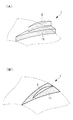
- the present invention is not limited to this, and as shown in FIG.
- the blade length of the hub side blade 6 may be shorter than that of the shroud side blade 3.
- FIG. 2A shows a perspective view
- FIG. 2B shows a top view of FIG.
- the hub side wing 6 has a wing length shorter than that of the shroud side wing 3.
- the leading edge of the hub side wing 6 is located at a midway position on the downstream side of the blade length of the shroud side wing 3.
- a connecting wall (connecting member) 7 is provided in the gap where the tip of the combined shroud side wing 3 and the tip of the hub side wing 4 are not in contact with each other substantially parallel to the shroud side wall surface 58 and the hub side wall surface. Yes. Since the front edge of the hub side wing 6 is located at a midway position on the downstream side of the shroud side wing 3, the connection wall 7 extends over the entire length of the hub side wing 6 from the front edge of the hub side wing 6 to the rear edge of the hub side wing 6. Will be provided.
- connection wall 7 of Modification 2 may cover a gap from the leading edge of the hub side blade 6 to the middle part of the blade length of the hub side blade 6 (for example, 60% of the blade length).
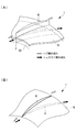
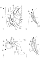
- the diffuser of the second embodiment is different from the first embodiment in that a disk for connecting all the tip portions of the shroud side wing and the hub side wing is provided, and the others are the same. Therefore, about the same structure, the same code
- the disk (connecting member) 8 continuously connects the tip portions of a plurality (only one blade is shown in FIG. 3) of the shroud side blade 3 and the hub side blade 4 in the circumferential direction.
- the disk 8 has an annular shape and is provided substantially parallel to the shroud side wall surface 58 and the hub side wall surface (not shown).
- the disk 8 has an annular shape like the shroud side wall surface 58 and the hub side wall surface.
- the annular disk 8 is provided from the front edge to the rear edge of the shroud side wing 3 and the hub side wing 4.
- the airflow (black arrow) guided from the front edge of the shroud side blade 3 to the shroud side blade 3 And the air flow (indicated by a white arrow) guided from the front edge of the hub side wing 4 to the hub side wing 4 can be separated. Therefore, the airflow does not pass through the gap where the tip portion of the combined shroud side blade 3 and the tip portion of the hub side blade 4 are not abutted, and it is possible to suppress the separation of the airflow and the generation of vortices due to the gap flow. it can.
- the disk (connection member) 8 continuously connects the entire tip portions of the shroud side wing 3 and the hub side wing 4 in an annular shape. Therefore, the gap generated between the shroud side wing 3 and the hub side wing 4 can be covered with the disk 8 to eliminate the gap flow. Thereby, generation
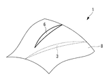
- the shroud side wing 3 and the hub side wing 4 have been described as having the same wing length.
- the present invention is not limited to this, and as shown in FIG.
- the blade length of the hub side blade 6 may be shorter than that of the shroud side blade 3.
- the blade length of the hub side blade 6 is shorter than that of the shroud side blade 3, and the circumferential phase between the hub side blade 3 and the shroud side blade 6 is changed. Also good.
- the hub-side wing 6 and the shroud-side wing 3 whose blade length is shorter than that of the shroud-side wing 3 are provided at positions in the circumferential direction different from each other, and do not overlap each other.
- the diffuser of the third embodiment is different from the second embodiment in that the inner diameters of the disks connecting the entire blade ends of the shroud side wing and the hub side wing are different, and the others are the same. Therefore, the description of the same configuration is omitted.
- An annular disk (connecting member) continuously connected in the circumferential direction between the tip ends of a plurality of shroud side blades and a plurality of hub side blades has an inner radius of each of the leading edges of the shroud side blades and the hub side blades. It is supposed to be smaller than the radius.
- the inner peripheral edge of the annular disk protrudes in the inner diameter direction from the front edges of the shroud side wing and the hub side wing, and the front edges of the shroud side wing and the hub side wing are provided in the middle of the disk in the radial direction. It will be.
- the diffuser of the centrifugal compressor according to the third embodiment and the centrifugal compressor including the diffuser have the following effects. According to a study by the inventors, even when the inner diameter of the annular disk (connecting member) is smaller than the leading edge radius of the shroud side wing and the hub side wing, the inner diameter of the annular disk is reduced to the shroud side wing and As in the case where the radius of the front edge of the hub side wing is the same, it has been found that the performance of the diffuser can be improved by eliminating the flow passing through the gap generated between the shroud side wing and the hub side wing.
- the diffuser of the fourth embodiment is different from the first embodiment in that the front edges of the shroud side wing and the hub side wing are shifted in the circumferential direction, and the other is the same. Therefore, about the same structure, the same code
- a fourth embodiment of the present invention will be described with reference to FIG.
- the shroud side wing 3 and the hub side wing 4 that are combined with each other are arranged such that the leading edges are shifted in the circumferential direction, and the trailing edges are also shifted from each other in the circumferential direction.
- the shroud side wing 3 and the hub side wing 4 are shifted in the circumferential direction so that they do not overlap at least 60% or less of the blade length from the blade leading edge.
- the shroud side wing 3 extends across the entire blade length direction from the front edge to the rear edge of the shroud side wing 3 and the hub side wing 4.
- the hub side wing 4 is separated. In addition, it may overlap after 60% of the blade length from the leading edge.
- the shroud side wing 3 and the hub side wing 4 are separated from the front edge to the rear edge of the shroud side wing 3 and the hub side wing 4, the shroud side wing combined as in the first embodiment.
- a gap may be formed after 60% of the blade length from the leading edge. It has been found that the gap 63 formed from the leading edge of one shroud side blade 3 or hub side blade 4 to 60% of the blade length significantly reduces the performance of the diffuser 1 due to the separation of the flow due to the gap flow and the generation of vortices. It is because of that.
- the diffuser 1 of the centrifugal compressor according to the fourth embodiment and the centrifugal compressor provided with the same have the following effects.
- Each front edge and each rear edge of the shroud side wing 3 and the hub side wing 4 combined with the shroud side wing 3 are provided to be shifted in the circumferential direction. Therefore, when the shroud side wing 3 and the hub side wing 4 are combined, there is no gap between the front end portions of the shroud side wing 3 and the hub side wing 4. Therefore, flow separation and vortex generation due to the gap flow can be prevented, and the performance of the diffuser 1 can be improved.
- the diffuser of the fifth embodiment is different from the fourth embodiment in that a disk is provided for connecting the tip portions of the shroud side wing and the hub side wing, and the others are the same. Therefore, about the same structure, the same code
- the disk (connecting member) 8 has an annular shape like the shroud side wall surface 58 and the hub side wall surface (not shown), and is provided substantially parallel to the shroud side wall surface 58 and the hub side wall surface.
- the annular disk 8 is provided from the front edge to the rear edge of the shroud side wing 3 and the hub side wing 4.
- the disk (connection member) 8 continuously connects the entire tip portions of the shroud side wing 3 and the hub side wing 4 in an annular shape. Therefore, the gap generated between the tip portions of the shroud side wing 3 and the hub side wing 4 can be covered by the disk 8 to eliminate the gap flow. Thereby, generation
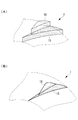
- the diffuser of the sixth embodiment is different from the first embodiment in that the tip portions of the shroud side wing and the hub side wing are abutted so that part of the blade thickness overlaps each other over the blade length, and the others are the same. It is. Therefore, about the same structure, the same code
- a sixth embodiment of the present invention will be described with reference to FIG.
- the shroud side wing 11 and the hub side wing 12 are thick wings having a wedge-shaped cross section perpendicular to the blade height direction.
- the shroud-side wing 11 and the hub-side wing 12 which are wedge-shaped thick wings have a substantially triangular cross-sectional shape perpendicular to the blade height direction, and gradually expand from the leading edge toward the trailing edge. ing.
- each tip end portion has an overlapping portion 13 (see FIG. 8B) in which part of the blade thickness overlaps with each other over the blade length.
- the diffuser 1 of the centrifugal compressor according to the sixth embodiment and the centrifugal compressor including the same have the following effects.
- the shroud side wing 11 and the hub side wing 12 have different entrance angles, and the tip portions in the blade height direction are abutted so that part of the blade thickness overlaps with each other over the blade length. Therefore, when the shroud side wing 11 and the hub side wing 12 are combined, there is no gap between the tip portions of the shroud side wing 11 and the hub side wing 12. Therefore, flow separation and vortex generation due to the gap flow can be prevented, and the performance of the diffuser 1 can be improved.
- the tip portions in the blade height direction of the shroud side wing 11 and the hub side wing 12 are attached so that part of the blade thickness overlaps each other over the blade length, the shroud side wing 11 and the hub side wing 12 Stiffness can be increased. Therefore, the vibration strength of the shroud side wing 11 and the hub side wing 12 can be improved.
- the shroud side wing 11 and the hub side wing 12 have been described as having the same blade length.
- the present invention is not limited to this, and as shown in FIG.
- the blade length of the hub side blade 14 may be shorter than that of the shroud side blade 11.
- the hub-side wing 14 has a shorter blade length than the shroud-side wing 11, so that a part of the blade thickness overlaps the shroud-side wing 11 and the hub-side wing 14 along the wing length and has a hub 13.
- the side wings 14 are combined so that the leading edge of the side wings 14 is located in the middle of the blade length of the shroud side wings 11.
- the diffuser of the seventh embodiment is different from the sixth embodiment in that the trailing edge thickness of the combined shroud side wing and hub side wing is thin, and the others are the same. Therefore, about the same structure, the same code
- a seventh embodiment of the present invention will be described with reference to FIG.
- the shroud side wing 15 and the hub side wing 16 are thick wings having a substantially wedge-shaped cross section perpendicular to the blade height direction.
- the substantially wedge-shaped shroud-side wing 15 and the hub-side wing 16 have a shape that gradually spreads from the front edge toward the rear edge.
- the blade thicknesses of the shroud-side wing 15 and the hub-side wing 16 are the center of the blade length. It becomes thinner from the middle of the downstream toward the trailing edge.
- the blade length on the suction surface side of the hub side blade 16 is substantially the same as the blade length on the pressure surface side of the shroud side blade 15 to form the overlapping portion 17.
- the diffuser 1 of the centrifugal compressor and the centrifugal compressor including the centrifugal compressor according to the seventh embodiment the following effects can be obtained.
- the blade thickness of each trailing edge is made thinner than the thickness of each blade at the center of the blade length. Therefore, the wake of the shroud side wing 15 and the hub side wing 16 can be reduced. Therefore, the performance of the diffuser 1 can be improved.
- the shroud side wing 15 and the hub side wing 16 are described as having the same wing length.
- the present invention is not limited to this, and as shown in FIG.
- the blade length of the hub side blade 18 may be shorter than that of the shroud side blade 15.
- the diffuser of the eighth embodiment is different from the sixth embodiment in that a thick blade shroud wing and a thin blade hub wing are combined, and the others are the same. Therefore, about the same structure, the same code
- an eighth embodiment of the present invention will be described with reference to FIG.
- the shroud side wing 11 is a thick wing whose wedge-shaped cross section is perpendicular to the blade height direction.
- the wedge-shaped shroud side wing 11 has a substantially triangular shape, and has a shape that gradually spreads from each front edge toward the rear edge.
- the hub side wing 4 is a thin wing.
- the shroud side wing 11 has a width of a cross-sectional shape perpendicular to the blade height of the hub side wing 4, which is a thin wing, about twice or more.
- the thick wing shroud side wing 11 and the thin wing hub side wing 4 are combined such that the entrance angles are different. Further, the blades are combined in a state where the tip in the blade height direction of the thin-blade hub side blade 4 is abutted with the tip in the blade height direction of the thick blade shroud side blade 11. Therefore, as shown in FIG. 12 (B), when viewed from above, the entire tip of the hub side blade 4 of the thin blade overlaps with a part of the tip of the shroud blade 11 of the thick blade.
- the diffuser 1 of the centrifugal compressor and the centrifugal compressor provided with the same according to the eighth embodiment the following effects can be obtained.
- the thick blade shroud side blade 11 and the thin blade hub side blade 4 have different inlet angles, and the entire tip of the hub side blade 4 in the blade height direction spans the blade length and part of the blade thickness of the shroud side blade 11. It was decided to face each other so as to overlap. Therefore, when the shroud side wing 11 and the hub side wing 4 are combined, there is no gap between the shroud side wing 11 and the hub side wing 4. Therefore, flow separation and vortex generation due to the gap flow can be prevented, and the performance of the diffuser 1 can be improved.
- the shroud side wing 11 and the hub side wing 4 have been described as having the same wing length.
- the present invention is not limited to this, and as shown in FIG.
- the blade length of the hub side blade 6 may be shorter than that of the shroud side blade 11.
- the cross-sectional shape perpendicular to the blade height direction of the shroud-side blade 11 that is a thick blade has been described as a wedge shape, but may be a channel type.
Landscapes
- Engineering & Computer Science (AREA)
- Mechanical Engineering (AREA)
- General Engineering & Computer Science (AREA)
- Structures Of Non-Positive Displacement Pumps (AREA)
Abstract
Description
本発明の第1の態様に係る遠心圧縮機のディフューザは、遠心羽根車の下流側に設けられるシュラウド側壁面と、該シュラウド側壁面に対向して設けられるハブ側壁面と、前記シュラウド側壁面に基端部が固定される複数のシュラウド側翼および前記ハブ側壁面に基端部が固定される複数のハブ側翼と、を有し、前記シュラウド側翼と前記ハブ側翼とは、入口角が異なるように、かつ、翼高さ方向における先端部の少なくとも一部分が互いに突き合わされる状態で組み合わされており、組み合わされた前記シュラウド側翼の前記先端部と前記ハブ側翼の前記先端部とが突き合わされていない隙間には、該隙間の少なくとも一部分を埋めるように互いの前記先端部間を接続する接続部材を備える。
また、シュラウド側翼とハブ側翼との各先端部間に生じた隙間を接続部材によって接続することとしたので、翼の剛性を高めることができる。したがって、翼の振動強度を向上させることができる。
また、接続部材の形状が円環状と簡素であることから、ディフューザの性能向上を低コストによって実現することができる。
また、シュラウド側翼とハブ側翼との翼高さ方向の先端部を翼長に渡って翼厚の一部が互いに重なるように付き合わすこととしたので、翼の剛性を高めることができる。したがって、翼の振動強度を向上させることができる。
なお、厚翼としては、薄翼に対して翼高さに直交する断面形状の幅が約2倍以上が好ましい。
また、シュラウド側翼とハブ側翼との各先端部間を接続部材で接続することとしたので、翼の剛性を高めることができる。したがって、翼の振動強度を向上させることができる。
本発明の第1実施形態に係る遠心圧縮機のディフューザに設けられているシュラウド側翼およびハブ側翼について、図1および図14を参照しながら説明する。
図1に示すディフューザ1は、遠心圧縮機50(図14参照)のハウジング51(図14参照)内で回転するインペラ53(図14参照)の外周端から吐出される気流(流れ)を減速することにより、気流の動圧を静圧に回復させるものである。このディフューザ1は、インペラ(遠心羽根車)53の下流側に設けられるシュラウド側壁面58と、シュラウド側壁面58に対向して設けられているハブ側壁面2と、シュラウド側壁面58に基端部が固定されている複数(図1には、1翼のみを示す。)のシュラウド側翼3と、ハブ側壁面2に基端部が固定されている複数(図1には、1翼のみを示す。)のハブ側翼4と、を有している。
組み合わされているシュラウド側翼3とハブ側翼4との各先端部が突き合わされずに生じた隙間63(図14参照)を埋めるように、シュラウド側翼3およびハブ側翼4の互いの先端部間を接続する接続壁(接続部材)5を設けることとした。これにより、シュラウド側翼3の先端部とハブ側壁翼4の先端部との間に生じる隙間63が接続壁5によって覆われる。そのため、隙間流れをなくすことができ、隙間流れによる流れの剥離や渦の発生を抑制することができる。したがって、ディフューザ1の性能向上を図ることができる。
また、シュラウド側翼3とハブ側翼4との各先端部間を接続壁5によって接続することとしたので、シュラウド側翼3およびハブ側翼4の剛性を高めることができる。したがって、シュラウド側翼3およびハブ側翼4の振動強度を向上させることができる。
ハブ側翼6は、シュラウド側翼3よりもその翼長が短いものとされている。ハブ側翼6の前縁は、シュラウド側翼3の翼長の下流側の途中位置に位置している。
第2実施形態のディフューザは、シュラウド側翼とハブ側翼との全先端部間を接続するディスクが設けられる点で、第1実施形態と相違し、その他は同様である。したがって、同一の構成については、同一の符号を付してその説明を省略する。
以下、本発明の第2実施形態について、図3を用いて説明する。
ディスク(接続部材)8は、複数(図3には、1翼のみを示す。)のシュラウド側翼3およびハブ側翼4の各先端部を円周方向に連続的に接続している。ディスク8は、円環状であり、シュラウド側壁面58およびハブ側壁面(図示せず)に略平行に設けられている。
ディスク(接続部材)8は、円環状にシュラウド側翼3およびハブ側翼4の全先端部間を連続的に接続している。そのため、シュラウド側翼3とハブ側翼4との間に生じる隙間をディスク8によって覆って、隙間流れをなくすことができる。これにより、隙間流れによる流れの剥離や渦の発生を抑制することができる。したがって、ディフューザ1の性能向上を図ることができる。
また、ディスク8の形状が円環状と簡素であることから、ディフューザ1の性能向上を低コストで実現することができる。
第3実施形態のディフューザは、シュラウド側翼とハブ側翼との全翼端部間を接続しているディスクの内径が異なる点で、第2実施形態と相違し、その他は同様である。したがって、同一の構成については、その説明を省略する。
発明者等が検討したところによると、円環状のディスク(接続部材)の内径をシュラウド側翼およびハブ側翼の前縁半径よりも小さくした場合であっても、円環状のディスクの内径をシュラウド側翼およびハブ側翼の前縁の半径と同じにした場合と同様に、シュラウド側翼とハブ側翼との間に生じる隙間を通過する流れをなくして、ディフューザの性能向上を図ることができるが分かった。
第4実施形態のディフューザは、シュラウド側翼とハブ側翼との前縁が周方向にずれて位置している点で、第1実施形態と相違し、その他は同様である。したがって、同一の構成については、同一の符号を付してその説明を省略する。
以下、本発明の第4実施形態について、図6を用いて説明する。
シュラウド側翼3とそれと組み合わされているハブ側翼4との各前縁および各後縁を円周方向に位置をずらして設けることとした。そのため、シュラウド側翼3とハブ側翼4とを組み合わせた際に、シュラウド側翼3とハブ側翼4との各前縁の先端部間に隙間が生じないこととなる。したがって、隙間流れによる流れの剥離や渦の発生を防止して、ディフューザ1の性能向上を図ることができる。
第5実施形態のディフューザは、シュラウド側翼とハブ側翼との先端部間を接続するディスクが設けられる点で、第4実施形態と相違し、その他は同様である。したがって、同一の構成については、同一の符号を付してその説明を省略する。
以下、本発明の第5実施形態について、図7を用いて説明する。
ディスク(接続部材)8は、シュラウド側壁面58およびハブ側壁面(図示せず)と同様に円環状であり、シュラウド側壁面58およびハブ側壁面に略平行に設けられている。円環状のディスク8は、シュラウド側翼3およびハブ側翼4の前縁から後縁に渡って設けられている。
ディスク(接続部材)8は、円環状にシュラウド側翼3およびハブ側翼4の全先端部間を連続的に接続している。そのため、シュラウド側翼3とハブ側翼4との各先端部間に生じる隙間をディスク8によって覆って、隙間流れをなくすことができる。これにより、隙間流れによる流れの剥離や渦の発生を抑制することができる。したがって、ディフューザ1の性能向上を図ることができる。
また、ディスク8の形状が円環状と簡素であることから、ディフューザ1の性能向上を低コストによって実現することができる。
第6実施形態のディフューザは、シュラウド側翼とハブ側翼との先端部が翼長に渡って翼厚の一部が互いに重なるように突き合わされる点で、第1実施形態と相違し、その他は同様である。したがって、同一の構成については、同一の符号を付してその説明を省略する。
以下、本発明の第6実施形態について、図8を用いて説明する。
シュラウド側翼11とハブ側翼12とは、入口角が異なり、それらの翼高さ方向の先端部が翼長に渡って翼厚の一部が互いに重なるように突き合わされていることとした。そのため、シュラウド側翼11とハブ側翼12とを組み合わせた際に、シュラウド側翼11とハブ側翼12との先端部間に隙間が生じないこととなる。したがって、隙間流れによる流れの剥離や渦の発生を防止して、ディフューザ1の性能向上を図ることができる。
また、シュラウド側翼11とハブ側翼12との翼高さ方向の先端部を翼長に渡って翼厚の一部が互いに重なるように付き合わすこととしたので、シュラウド側翼11とハブ側翼12との剛性を高めることができる。したがって、シュラウド側翼11とハブ側翼12との振動強度を向上させることができる。
第7実施形態のディフューザは、組み合わせたシュラウド側翼とハブ側翼との後縁の翼厚が薄い点で、第6実施形態と相違し、その他は同様である。したがって、同一の構成については、同一の符号を付してその説明を省略する。
以下、本発明の第7実施形態について、図10を用いて説明する。
シュラウド側翼15およびハブ側翼16は、翼長中央部の各翼厚に比べて各後縁の翼厚を薄くすることとした。そのため、シュラウド側翼15およびハブ側翼16の後流を小さくすることができる。したがって、ディフューザ1の性能向上を図ることができる。
第8実施形態のディフューザは、厚翼のシュラウド側翼と薄翼のハブ側翼とを組み合わせる点で、第6実施形態と相違し、その他は同様である。したがって、同一の構成については、同一の符号を付してその説明を省略する。
以下、本発明の第8実施形態について、図12を用いて説明する。
厚翼のシュラウド側翼11と薄翼のハブ側翼4とは、入口角が異なり、ハブ側翼4の翼高さ方向の先端部全体が翼長に渡ってシュラウド側翼11の翼厚の一部と互いに重なるように突き合わされることとした。そのため、シュラウド側翼11とハブ側翼4とを組み合わせた際に、シュラウド側翼11とハブ側翼4との間に隙間が生じないこととなる。したがって、隙間流れによる流れの剥離や渦の発生を防止して、ディフューザ1の性能向上を図ることができる。
3 シュラウド側翼
4 ハブ側翼
5 接続壁(接続部材)
58 シュラウド側壁面
Claims (10)
- 遠心羽根車の下流側に設けられるシュラウド側壁面と、
該シュラウド側壁面に対向して設けられるハブ側壁面と、
前記シュラウド側壁面に基端部が固定される複数のシュラウド側翼および前記ハブ側壁面に基端部が固定される複数のハブ側翼と、を有し、
前記シュラウド側翼と前記ハブ側翼とは、入口角が異なるように、かつ、翼高さ方向における先端部の少なくとも一部分が互いに突き合わされる状態で組み合わされており、
組み合わされた前記シュラウド側翼の前記先端部と前記ハブ側翼の前記先端部とが突き合わされていない隙間には、該隙間の少なくとも一部分を埋めるように互いの前記先端部間を接続する接続部材を備える遠心圧縮機のディフューザ。 - 前記接続部材の形状は、複数の前記シュラウド側翼および複数の前記ハブ側翼の前記先端部間を円周方向に連続的に接続する円環状である請求項1に記載の遠心圧縮機のディフューザ。
- 円環状の前記接続部材は、その内径が前記シュラウド側翼および前記ハブ側翼の前縁半径よりも小さい請求項2に記載の遠心圧縮機のディフューザ。
- 前記接続部材は、組み合わされた前記シュラウド側翼の前記先端部または前記ハブ側翼の前記先端部の少なくとも一方の前縁から翼長の60%下流までを埋めるように接続する請求項1から請求項3のいずれかに記載の遠心圧縮機のディフューザ。
- 組み合わされる前記シュラウド側翼と前記ハブ側翼とは、各々前縁を円周方向に位置をずらして配置される請求項1から請求項4のいずれかに記載の遠心圧縮機のディフューザ。
- 組み合わされる前記シュラウド側翼と前記ハブ側翼とは、前縁から翼長の60%までが重ならないように各々円周方向に位置をずらして配置される請求項1から請求項4のいずれかに記載の遠心圧縮機のディフューザ。
- 遠心羽根車の下流側に設けられるシュラウド側壁面と、
該シュラウド側壁面に対向して設けられるハブ側壁面と、
前記シュラウド側壁面に基端部が固定される複数のシュラウド側翼および前記ハブ側壁面に基端部が固定される複数のハブ側翼と、を有し、
前記シュラウド側翼と前記ハブ側翼とは、入口角が異なるように、かつ、翼高さ方向における先端部が翼長に渡って翼厚の一部が互いに重なるように突き合わされる状態で組み合わされている遠心圧縮機のディフューザ。 - 前記シュラウド側翼および前記ハブ側翼の各後縁の翼厚が翼長中央部の翼厚に比べて薄い請求項7に記載の遠心圧縮機のディフューザ。
- 前記シュラウド側翼または前記ハブ側翼のどちらか一方を厚翼とし、他方を薄翼とした請求項7または請求項8に記載の遠心圧縮機のディフューザ。
- 請求項1から請求項9のいずれかに記載の遠心圧縮機のディフューザを備える遠心圧縮機。
Priority Applications (5)
| Application Number | Priority Date | Filing Date | Title |
|---|---|---|---|
| KR1020147006268A KR101437319B1 (ko) | 2010-08-31 | 2011-08-17 | 원심 압축기의 디퓨저 및 이것을 구비한 원심 압축기 |
| EP11821560.7A EP2613056B1 (en) | 2010-08-31 | 2011-08-17 | Centrifugal compressor diffuser and centrifugal compressor provided with the same |
| CN201180032174.0A CN103097741B (zh) | 2010-08-31 | 2011-08-17 | 离心压缩机的扩散器及具备该扩散器的离心压缩机 |
| US13/806,384 US20130094955A1 (en) | 2010-08-31 | 2011-08-17 | Centrifugal compressor diffuser and centrifugal compressor provided with the same |
| KR1020127034017A KR101454100B1 (ko) | 2010-08-31 | 2011-08-17 | 원심 압축기의 디퓨저 및 이것을 구비한 원심 압축기 |
Applications Claiming Priority (2)
| Application Number | Priority Date | Filing Date | Title |
|---|---|---|---|
| JP2010193623A JP5010722B2 (ja) | 2010-08-31 | 2010-08-31 | 遠心圧縮機のディフューザおよびこれを備えた遠心圧縮機 |
| JP2010-193623 | 2010-08-31 |
Publications (1)
| Publication Number | Publication Date |
|---|---|
| WO2012029543A1 true WO2012029543A1 (ja) | 2012-03-08 |
Family
ID=45772647
Family Applications (1)
| Application Number | Title | Priority Date | Filing Date |
|---|---|---|---|
| PCT/JP2011/068611 WO2012029543A1 (ja) | 2010-08-31 | 2011-08-17 | 遠心圧縮機のディフューザおよびこれを備えた遠心圧縮機 |
Country Status (6)
| Country | Link |
|---|---|
| US (1) | US20130094955A1 (ja) |
| EP (1) | EP2613056B1 (ja) |
| JP (1) | JP5010722B2 (ja) |
| KR (2) | KR101454100B1 (ja) |
| CN (1) | CN103097741B (ja) |
| WO (1) | WO2012029543A1 (ja) |
Cited By (2)
| Publication number | Priority date | Publication date | Assignee | Title |
|---|---|---|---|---|
| JP2018514691A (ja) * | 2015-04-30 | 2018-06-07 | コンセプツ エヌアールイーシー,エルエルシー | ディフューザにおける偏向通路およびこうしたディフューザを設計する対応する方法 |
| CN109790853A (zh) * | 2016-12-07 | 2019-05-21 | 三菱重工发动机和增压器株式会社 | 离心压缩机以及涡轮增压器 |
Families Citing this family (8)
| Publication number | Priority date | Publication date | Assignee | Title |
|---|---|---|---|---|
| JP6109635B2 (ja) * | 2013-04-30 | 2017-04-05 | 三菱重工業株式会社 | ディフューザの加工方法、及びディフューザの調整方法 |
| JP6388772B2 (ja) * | 2014-02-25 | 2018-09-12 | 三菱重工業株式会社 | 遠心圧縮機およびディフューザ製造方法 |
| US10458432B2 (en) * | 2017-04-25 | 2019-10-29 | Garrett Transportation I Inc. | Turbocharger compressor assembly with vaned divider |
| EP3460257A1 (de) | 2017-09-20 | 2019-03-27 | Siemens Aktiengesellschaft | Durchströmbare anordnung |
| US11067098B2 (en) | 2018-02-02 | 2021-07-20 | Carrier Corporation | Silencer for a centrifugal compressor assembly |
| US10851801B2 (en) * | 2018-03-02 | 2020-12-01 | Ingersoll-Rand Industrial U.S., Inc. | Centrifugal compressor system and diffuser |
| JP7005393B2 (ja) | 2018-03-09 | 2022-01-21 | 三菱重工業株式会社 | ディフューザベーン及び遠心圧縮機 |
| CN110878768A (zh) * | 2019-12-20 | 2020-03-13 | 中国北方发动机研究所(天津) | 一种具有变进口叶片角型导流叶片的有叶扩压器结构 |
Citations (3)
| Publication number | Priority date | Publication date | Assignee | Title |
|---|---|---|---|---|
| JPS60184999A (ja) * | 1984-03-02 | 1985-09-20 | Hitachi Ltd | 遠心形流体機械の羽根付きデイフユ−ザ |
| JP3746740B2 (ja) | 2002-06-25 | 2006-02-15 | 三菱重工業株式会社 | 遠心圧縮機 |
| JP2011089460A (ja) * | 2009-10-22 | 2011-05-06 | Hitachi Plant Technologies Ltd | ターボ型流体機械 |
Family Cites Families (9)
| Publication number | Priority date | Publication date | Assignee | Title |
|---|---|---|---|---|
| CN85202558U (zh) * | 1985-06-24 | 1986-08-06 | 开封空分设备厂 | 离心式鼓风机、压缩机叶片扩压器 |
| DE3882463T2 (de) * | 1987-09-01 | 1993-11-11 | Hitachi Ltd | Diffusor für Zentrifugalverdichter. |
| DE4231452C2 (de) * | 1992-09-19 | 1994-11-03 | Gutehoffnungshuette Man | Turbokompressor mit einem Austrittsgehäuse für entgegengesetzte Drehrichtung |
| CN100374733C (zh) * | 2004-02-23 | 2008-03-12 | 孙敏超 | 一种径向单列叶片扩压器 |
| JP2007255220A (ja) | 2006-03-20 | 2007-10-04 | Toyota Motor Corp | 可変ディフューザ付き遠心圧縮機 |
| EP1860325A1 (de) * | 2006-05-26 | 2007-11-28 | ABB Turbo Systems AG | Diffusor |
| JP4795912B2 (ja) * | 2006-10-30 | 2011-10-19 | 三菱重工業株式会社 | 可変ディフューザ及び圧縮機 |
| CN101542128B (zh) * | 2007-04-20 | 2011-05-25 | 三菱重工业株式会社 | 离心压缩机 |
| JP5003325B2 (ja) | 2007-07-11 | 2012-08-15 | 株式会社Ihi | 遠心圧縮機のディフューザ構造 |
-
2010
- 2010-08-31 JP JP2010193623A patent/JP5010722B2/ja not_active Expired - Fee Related
-
2011
- 2011-08-17 CN CN201180032174.0A patent/CN103097741B/zh not_active Expired - Fee Related
- 2011-08-17 WO PCT/JP2011/068611 patent/WO2012029543A1/ja active Application Filing
- 2011-08-17 EP EP11821560.7A patent/EP2613056B1/en not_active Not-in-force
- 2011-08-17 KR KR1020127034017A patent/KR101454100B1/ko not_active IP Right Cessation
- 2011-08-17 KR KR1020147006268A patent/KR101437319B1/ko not_active IP Right Cessation
- 2011-08-17 US US13/806,384 patent/US20130094955A1/en not_active Abandoned
Patent Citations (3)
| Publication number | Priority date | Publication date | Assignee | Title |
|---|---|---|---|---|
| JPS60184999A (ja) * | 1984-03-02 | 1985-09-20 | Hitachi Ltd | 遠心形流体機械の羽根付きデイフユ−ザ |
| JP3746740B2 (ja) | 2002-06-25 | 2006-02-15 | 三菱重工業株式会社 | 遠心圧縮機 |
| JP2011089460A (ja) * | 2009-10-22 | 2011-05-06 | Hitachi Plant Technologies Ltd | ターボ型流体機械 |
Non-Patent Citations (1)
| Title |
|---|
| See also references of EP2613056A4 |
Cited By (5)
| Publication number | Priority date | Publication date | Assignee | Title |
|---|---|---|---|---|
| JP2018514691A (ja) * | 2015-04-30 | 2018-06-07 | コンセプツ エヌアールイーシー,エルエルシー | ディフューザにおける偏向通路およびこうしたディフューザを設計する対応する方法 |
| JP2021050739A (ja) * | 2015-04-30 | 2021-04-01 | コンセプツ エヌアールイーシー,エルエルシー | ディフューザにおける偏向通路およびこうしたディフューザを設計する対応する方法 |
| JP7319245B2 (ja) | 2015-04-30 | 2023-08-01 | コンセプツ エヌアールイーシー,エルエルシー | ディフューザにおける偏向通路およびこうしたディフューザを設計する対応する方法 |
| CN109790853A (zh) * | 2016-12-07 | 2019-05-21 | 三菱重工发动机和增压器株式会社 | 离心压缩机以及涡轮增压器 |
| CN109790853B (zh) * | 2016-12-07 | 2021-10-08 | 三菱重工发动机和增压器株式会社 | 离心压缩机以及涡轮增压器 |
Also Published As
| Publication number | Publication date |
|---|---|
| KR101454100B1 (ko) | 2014-10-22 |
| KR20130045280A (ko) | 2013-05-03 |
| CN103097741A (zh) | 2013-05-08 |
| EP2613056A4 (en) | 2014-04-09 |
| EP2613056B1 (en) | 2016-01-20 |
| CN103097741B (zh) | 2015-11-25 |
| KR20140049052A (ko) | 2014-04-24 |
| US20130094955A1 (en) | 2013-04-18 |
| KR101437319B1 (ko) | 2014-09-02 |
| JP5010722B2 (ja) | 2012-08-29 |
| EP2613056A1 (en) | 2013-07-10 |
| JP2012052432A (ja) | 2012-03-15 |
Similar Documents
| Publication | Publication Date | Title |
|---|---|---|
| JP5010722B2 (ja) | 遠心圧縮機のディフューザおよびこれを備えた遠心圧縮機 | |
| US9897101B2 (en) | Impeller for centrifugal rotary machine, and centrifugal rotary machine | |
| JP4924984B2 (ja) | 軸流圧縮機の翼列 | |
| JP2008075536A5 (ja) | ||
| WO2014087690A1 (ja) | 遠心圧縮機 | |
| WO2018159681A1 (ja) | タービン及びガスタービン | |
| JP5022523B2 (ja) | 遠心圧縮機のディフューザおよびこれを備えた遠心圧縮機 | |
| US11187242B2 (en) | Multi-stage centrifugal compressor | |
| US10844863B2 (en) | Centrifugal rotary machine | |
| WO2019107488A1 (ja) | 多段遠心圧縮機、ケーシング及びリターンベーン | |
| JP2016079919A (ja) | 動翼及び軸流タービン | |
| EP3708847B1 (en) | Centrifugal compressor and turbocharger comprising said centrifugal compressor | |
| JP6215154B2 (ja) | 回転機械 | |
| WO2022029932A1 (ja) | 遠心圧縮機のインペラ及び遠心圧縮機 | |
| WO2017072844A1 (ja) | 回転機械 | |
| US11421546B2 (en) | Nozzle vane | |
| JP7232332B2 (ja) | 遠心圧縮機のスクロール構造及び遠心圧縮機 | |
| WO2023187913A1 (ja) | 斜流タービン及びターボチャージャ | |
| JP2023068953A (ja) | ベーンドディフューザおよび遠心圧縮機 | |
| JP2004353607A (ja) | 遠心圧縮機 | |
| JP5589989B2 (ja) | 遠心送風機 | |
| JP2016169672A (ja) | 遠心ポンプ |
Legal Events
| Date | Code | Title | Description |
|---|---|---|---|
| WWE | Wipo information: entry into national phase |
Ref document number: 201180032174.0 Country of ref document: CN |
|
| 121 | Ep: the epo has been informed by wipo that ep was designated in this application |
Ref document number: 11821560 Country of ref document: EP Kind code of ref document: A1 |
|
| WWE | Wipo information: entry into national phase |
Ref document number: 2011821560 Country of ref document: EP |
|
| WWE | Wipo information: entry into national phase |
Ref document number: 13806384 Country of ref document: US |
|
| ENP | Entry into the national phase |
Ref document number: 20127034017 Country of ref document: KR Kind code of ref document: A |
|
| NENP | Non-entry into the national phase |
Ref country code: DE |