WO2012020654A1 - センサ付車輪用軸受 - Google Patents
センサ付車輪用軸受 Download PDFInfo
- Publication number
- WO2012020654A1 WO2012020654A1 PCT/JP2011/067463 JP2011067463W WO2012020654A1 WO 2012020654 A1 WO2012020654 A1 WO 2012020654A1 JP 2011067463 W JP2011067463 W JP 2011067463W WO 2012020654 A1 WO2012020654 A1 WO 2012020654A1
- Authority
- WO
- WIPO (PCT)
- Prior art keywords
- sensor
- load
- unit
- estimation
- wheel bearing
- Prior art date
- Legal status (The legal status is an assumption and is not a legal conclusion. Google has not performed a legal analysis and makes no representation as to the accuracy of the status listed.)
- Ceased
Links
Images









Classifications
-
- F—MECHANICAL ENGINEERING; LIGHTING; HEATING; WEAPONS; BLASTING
- F16—ENGINEERING ELEMENTS AND UNITS; GENERAL MEASURES FOR PRODUCING AND MAINTAINING EFFECTIVE FUNCTIONING OF MACHINES OR INSTALLATIONS; THERMAL INSULATION IN GENERAL
- F16C—SHAFTS; FLEXIBLE SHAFTS; ELEMENTS OR CRANKSHAFT MECHANISMS; ROTARY BODIES OTHER THAN GEARING ELEMENTS; BEARINGS
- F16C33/00—Parts of bearings; Special methods for making bearings or parts thereof
- F16C33/30—Parts of ball or roller bearings
- F16C33/58—Raceways; Race rings
- F16C33/583—Details of specific parts of races
- F16C33/586—Details of specific parts of races outside the space between the races, e.g. end faces or bore of inner ring
-
- B—PERFORMING OPERATIONS; TRANSPORTING
- B60—VEHICLES IN GENERAL
- B60B—VEHICLE WHEELS; CASTORS; AXLES FOR WHEELS OR CASTORS; INCREASING WHEEL ADHESION
- B60B27/00—Hubs
- B60B27/0005—Hubs with ball bearings
-
- B—PERFORMING OPERATIONS; TRANSPORTING
- B60—VEHICLES IN GENERAL
- B60B—VEHICLE WHEELS; CASTORS; AXLES FOR WHEELS OR CASTORS; INCREASING WHEEL ADHESION
- B60B27/00—Hubs
- B60B27/0047—Hubs characterised by functional integration of other elements
- B60B27/0068—Hubs characterised by functional integration of other elements the element being a sensor
-
- B—PERFORMING OPERATIONS; TRANSPORTING
- B60—VEHICLES IN GENERAL
- B60B—VEHICLE WHEELS; CASTORS; AXLES FOR WHEELS OR CASTORS; INCREASING WHEEL ADHESION
- B60B27/00—Hubs
- B60B27/0094—Hubs one or more of the bearing races are formed by the hub
-
- F—MECHANICAL ENGINEERING; LIGHTING; HEATING; WEAPONS; BLASTING
- F16—ENGINEERING ELEMENTS AND UNITS; GENERAL MEASURES FOR PRODUCING AND MAINTAINING EFFECTIVE FUNCTIONING OF MACHINES OR INSTALLATIONS; THERMAL INSULATION IN GENERAL
- F16C—SHAFTS; FLEXIBLE SHAFTS; ELEMENTS OR CRANKSHAFT MECHANISMS; ROTARY BODIES OTHER THAN GEARING ELEMENTS; BEARINGS
- F16C19/00—Bearings with rolling contact, for exclusively rotary movement
- F16C19/52—Bearings with rolling contact, for exclusively rotary movement with devices affected by abnormal or undesired conditions
- F16C19/522—Bearings with rolling contact, for exclusively rotary movement with devices affected by abnormal or undesired conditions related to load on the bearing, e.g. bearings with load sensors or means to protect the bearing against overload
-
- G—PHYSICS
- G01—MEASURING; TESTING
- G01L—MEASURING FORCE, STRESS, TORQUE, WORK, MECHANICAL POWER, MECHANICAL EFFICIENCY, OR FLUID PRESSURE
- G01L1/00—Measuring force or stress, in general
- G01L1/20—Measuring force or stress, in general by measuring variations in ohmic resistance of solid materials or of electrically-conductive fluids; by making use of electrokinetic cells, i.e. liquid-containing cells wherein an electrical potential is produced or varied upon the application of stress
- G01L1/22—Measuring force or stress, in general by measuring variations in ohmic resistance of solid materials or of electrically-conductive fluids; by making use of electrokinetic cells, i.e. liquid-containing cells wherein an electrical potential is produced or varied upon the application of stress using resistance strain gauges
- G01L1/2268—Arrangements for correcting or for compensating unwanted effects
- G01L1/2281—Arrangements for correcting or for compensating unwanted effects for temperature variations
-
- G—PHYSICS
- G01—MEASURING; TESTING
- G01L—MEASURING FORCE, STRESS, TORQUE, WORK, MECHANICAL POWER, MECHANICAL EFFICIENCY, OR FLUID PRESSURE
- G01L5/00—Apparatus for, or methods of, measuring force, work, mechanical power, or torque, specially adapted for specific purposes
- G01L5/0009—Force sensors associated with a bearing
-
- G—PHYSICS
- G01—MEASURING; TESTING
- G01L—MEASURING FORCE, STRESS, TORQUE, WORK, MECHANICAL POWER, MECHANICAL EFFICIENCY, OR FLUID PRESSURE
- G01L5/00—Apparatus for, or methods of, measuring force, work, mechanical power, or torque, specially adapted for specific purposes
- G01L5/16—Apparatus for, or methods of, measuring force, work, mechanical power, or torque, specially adapted for specific purposes for measuring several components of force
- G01L5/161—Apparatus for, or methods of, measuring force, work, mechanical power, or torque, specially adapted for specific purposes for measuring several components of force using variations in ohmic resistance
- G01L5/1627—Apparatus for, or methods of, measuring force, work, mechanical power, or torque, specially adapted for specific purposes for measuring several components of force using variations in ohmic resistance of strain gauges
-
- G—PHYSICS
- G01—MEASURING; TESTING
- G01P—MEASURING LINEAR OR ANGULAR SPEED, ACCELERATION, DECELERATION, OR SHOCK; INDICATING PRESENCE, ABSENCE, OR DIRECTION, OF MOVEMENT
- G01P3/00—Measuring linear or angular speed; Measuring differences of linear or angular speeds
- G01P3/42—Devices characterised by the use of electric or magnetic means
- G01P3/44—Devices characterised by the use of electric or magnetic means for measuring angular speed
- G01P3/443—Devices characterised by the use of electric or magnetic means for measuring angular speed mounted in bearings
-
- F—MECHANICAL ENGINEERING; LIGHTING; HEATING; WEAPONS; BLASTING
- F16—ENGINEERING ELEMENTS AND UNITS; GENERAL MEASURES FOR PRODUCING AND MAINTAINING EFFECTIVE FUNCTIONING OF MACHINES OR INSTALLATIONS; THERMAL INSULATION IN GENERAL
- F16C—SHAFTS; FLEXIBLE SHAFTS; ELEMENTS OR CRANKSHAFT MECHANISMS; ROTARY BODIES OTHER THAN GEARING ELEMENTS; BEARINGS
- F16C19/00—Bearings with rolling contact, for exclusively rotary movement
- F16C19/02—Bearings with rolling contact, for exclusively rotary movement with bearing balls essentially of the same size in one or more circular rows
- F16C19/14—Bearings with rolling contact, for exclusively rotary movement with bearing balls essentially of the same size in one or more circular rows for both radial and axial load
- F16C19/18—Bearings with rolling contact, for exclusively rotary movement with bearing balls essentially of the same size in one or more circular rows for both radial and axial load with two or more rows of balls
- F16C19/181—Bearings with rolling contact, for exclusively rotary movement with bearing balls essentially of the same size in one or more circular rows for both radial and axial load with two or more rows of balls with angular contact
- F16C19/183—Bearings with rolling contact, for exclusively rotary movement with bearing balls essentially of the same size in one or more circular rows for both radial and axial load with two or more rows of balls with angular contact with two rows at opposite angles
- F16C19/184—Bearings with rolling contact, for exclusively rotary movement with bearing balls essentially of the same size in one or more circular rows for both radial and axial load with two or more rows of balls with angular contact with two rows at opposite angles in O-arrangement
- F16C19/186—Bearings with rolling contact, for exclusively rotary movement with bearing balls essentially of the same size in one or more circular rows for both radial and axial load with two or more rows of balls with angular contact with two rows at opposite angles in O-arrangement with three raceways provided integrally on parts other than race rings, e.g. third generation hubs
-
- F—MECHANICAL ENGINEERING; LIGHTING; HEATING; WEAPONS; BLASTING
- F16—ENGINEERING ELEMENTS AND UNITS; GENERAL MEASURES FOR PRODUCING AND MAINTAINING EFFECTIVE FUNCTIONING OF MACHINES OR INSTALLATIONS; THERMAL INSULATION IN GENERAL
- F16C—SHAFTS; FLEXIBLE SHAFTS; ELEMENTS OR CRANKSHAFT MECHANISMS; ROTARY BODIES OTHER THAN GEARING ELEMENTS; BEARINGS
- F16C2326/00—Articles relating to transporting
- F16C2326/01—Parts of vehicles in general
- F16C2326/02—Wheel hubs or castors
-
- F—MECHANICAL ENGINEERING; LIGHTING; HEATING; WEAPONS; BLASTING
- F16—ENGINEERING ELEMENTS AND UNITS; GENERAL MEASURES FOR PRODUCING AND MAINTAINING EFFECTIVE FUNCTIONING OF MACHINES OR INSTALLATIONS; THERMAL INSULATION IN GENERAL
- F16C—SHAFTS; FLEXIBLE SHAFTS; ELEMENTS OR CRANKSHAFT MECHANISMS; ROTARY BODIES OTHER THAN GEARING ELEMENTS; BEARINGS
- F16C41/00—Other accessories, e.g. devices integrated in the bearing not relating to the bearing function as such
Definitions
- This invention relates to a wheel bearing with a sensor having a built-in load detection sensor for detecting a load applied to a bearing portion of the wheel.
- the wheel bearing in the sensor-equipped wheel bearing of the same document includes an outer member in which a double row rolling surface is formed on the inner periphery, and an inner member in which the rolling surface opposite to the rolling surface is formed on the outer periphery.
- a member and a double row rolling element interposed between the opposing rolling surfaces of both members are provided, and the wheel is rotatably supported with respect to the vehicle body.
- a sensor unit comprising two sensor units arranged on the outer diameter surface of the fixed side member of the outer member and the inner member at a position that forms a phase difference of 180 degrees in the circumferential direction of the fixed side member. At least one pair is provided.
- Each sensor unit has a strain generating member having two or more contact fixing portions fixed in contact with the outer diameter surface of the fixed side member, and detects the strain of the strain generating member attached to the strain generating member. It shall have a sensor.
- the radial load estimating means estimates the radial load acting in the radial direction of the wheel bearing. Further, based on the sum of the sensor output signals of the two sensor units in the sensor unit pair, the axial load acting means estimates the axial load acting in the axial direction of the wheel bearing. Then, the two sensor units of at least one pair of sensor units are arranged on the upper surface portion and the lower surface portion of the outer diameter surface of the fixed side member that is in the vertical position with respect to the tire ground contact surface. Based on the output signal amplitude of the sensor of the sensor unit pair, the axial load direction determining means determines the direction of the axial load. An outline of the load estimation process in this case is shown in a block diagram in FIG.
- the axial load is determined based on the difference between the amplitude values (vibration components accompanying the revolution motion of the rolling elements) in the sensor output signals of the two sensor units arranged above and below, and depending on whether the axial load is positive or negative, Since the load is calculated using load estimation parameters suitable for each, the load can be estimated with high sensitivity.
- the present inventors have developed a new load estimation means in the sensor-equipped wheel bearing having the configuration shown in the block diagram of FIG.
- a formula using only the average value A of the sensor output signal as a variable and a formula using the average value A and the amplitude value B of the sensor output signal as variables are prepared.
- the load calculation process is switched. That is, in the normal running state, the load estimation calculation is performed by an arithmetic expression using the average value A and the amplitude value B of the sensor output signal, and the load estimation calculation by the arithmetic expression using only the average value A is performed at a low speed or in a stop state. I do.
- rotation speed information is used to determine the rotation speed.
- the object of the present invention is to provide a simple structure and switch the calculation method according to the vehicle speed without providing an additional sensor or the like, improve the estimation accuracy of the load applied to the wheel, It is intended to provide a sensor-equipped wheel bearing that can be reduced in size by reducing the installation space, and that can improve reliability by simplifying the configuration.
- the sensor-equipped wheel bearing according to the present invention includes an outer member 1 in which double-row rolling surfaces are formed on the inner periphery, and an inner member 2 in which a rolling surface opposite to the rolling surface is formed on the outer periphery. And a double-row rolling element 5 interposed between the opposing rolling surfaces of both members, and a sensor-equipped wheel bearing for rotatably supporting the wheel with respect to the vehicle body, wherein the outer member 1 and the inner member A plurality of load detection sensor units 20 are provided on a fixed side member of the side member 2, and the sensor unit 20 has two or more contact fixing portions 21a fixed in contact with the fixed side member.
- the load estimation calculation unit 35 calculates the load acting on the wheel bearing by applying the estimated calculation formula and the load estimation calculation unit 35 according to the rotation speed region determined by the rotation speed region determination unit 32. And a load calculation condition determination unit 34 for switching parameters in the estimation calculation formula used.
- the above “total sum of values indicating variation amount” is, for example, a sum of standard deviations of input data.
- the load estimating means 30 calculates the sum of the values indicating the variation amount of the sensor output signal of each sensor unit 20, and the rotation speed area determination unit 32 uses the calculated value as an evaluation value. Is determined.
- the load calculation condition determination unit 34 switches the parameters of the estimation calculation formula used in the load estimation calculation unit 35 according to the determined rotation speed region. Therefore, it is possible to reliably estimate the load applied to the wheel by switching from the sensor output signal of the sensor unit 20 to the arithmetic processing according to the wheel rotation speed region without detecting the wheel rotation speed. For this reason, without providing an additional sensor or the like, the calculation method can be switched according to the vehicle speed with a simple structure, and the estimation accuracy of the load applied to the wheel can be improved. Further, the installation space for sensors and wiring can be reduced and the size can be reduced, and the reliability can be improved by simplifying the configuration.
- the rotational speed region determination unit 32 compares the evaluation value with a predetermined threshold value, and the wheel is in a predetermined normal rotational speed region or a low rotational speed region. It is good also as what discriminate
- region determination part 32 compares the said evaluation value with two or more defined threshold values, and a wheel is any of three or more defined rotational speed areas. It is good also as what discriminate
- the load calculation condition determination unit 34 is used by the load estimation calculation unit 35 after a predetermined time has elapsed when the rotation speed region determination unit 32 determines that the rotation speed region is the lowest low speed rotation region.
- the parameter of the estimation calculation formula may be switched to a predetermined specified parameter.
- the parameter of the estimation calculation formula is reset to the initial value after a lapse of a fixed time after it is determined that the rotation speed range is the lowest. This is particularly effective when the rotation speed region determination unit 32 performs processing according to the axial load. If the speed is almost stationary and low, the parameters may not be switched according to changes in the axial load, etc., but by resetting the parameters of the estimation formula to the initial values, the load estimation accuracy at low speed is improved. Can be made.
- the load estimating means 30 operates in the vertical direction and the left-right direction acting on the radial direction of the wheel bearing from the output signals of the sensors of the three or more sensor units 20. It is good also as what estimates the load of 3 directions of these two radial loads and one axial load which acts on an axial direction.
- the sensor unit is arranged at 90 degrees in the circumferential direction on the upper surface portion, the lower surface portion, the right surface portion, and the left surface portion of the outer diameter surface of the fixed side member that is in the vertical position and the horizontal position with respect to the tire ground contact surface. Four of them may be equally arranged with a phase difference.
- the load estimation calculation unit 35 includes a plurality of the estimation calculation formulas, and the calculation formula selection unit 35a that selects the plurality of estimation calculation formulas according to a selection command.
- the load estimation means 30 includes a direction determination unit 33 that determines the direction of the axial load by using the difference in the amplitude value of the output signals of the sensors of the two sensor units 20 disposed opposite to the vertical position.
- the load calculation condition determination unit 34 corresponds to the determination result of the parameter determination unit 34a that switches the parameter of the estimation calculation formula used in the load estimation calculation unit 35 and the direction determination unit 33.
- the load estimation means 30 has a pre-processing unit 31 that calculates an average value and an amplitude value of the output signals of each sensor in each sensor unit within a predetermined time, and the estimation calculation of the load estimation calculation unit 35
- the equation may calculate the load using only the average value, only the amplitude value, or both the average value and the amplitude value.
- the rotation speed region determined by the rotation speed region determination unit 32 is a low speed region
- an equation using an average value is adopted as an estimation calculation formula in the load estimation calculation unit 35, and the rotation speed region is normal.
- the sensor unit 20 has three or more contact fixing portions 21a and two sensors 22, and is adjacent between the first and second contact fixing portions 21a and between the adjacent second and third contact fixing portions 21a.
- the sensors 22 are respectively mounted between the contact fixing portions 21a, and the distance between the adjacent contact fixing portions 21a or the adjacent sensors 22 in the circumferential direction of the fixed side member is ⁇ 1/2 + n of the arrangement pitch of the rolling elements 5. (N: integer) ⁇ times, and the load estimation means 30 may use the sum of the output signals of the two sensors 22 as an average value.
- the output signals of the two sensors 22 have a phase difference of about 180 degrees, and the average value is a value obtained by canceling the fluctuation component due to the rolling element passage.
- the amplitude value is an accurate value that more reliably eliminates the effects of temperature and the effects of slippage between the knuckle and flange surfaces.
- each sensor unit 22 may be provided with a temperature sensor 36, and the sensor output signal of the sensor unit 22 may be corrected based on the output signal of the temperature sensor 36.
- the temperature drift of the sensor output signal of the sensor unit 22 can be corrected, and the load can be easily estimated with higher accuracy.
- FIG. 4 is a sectional view taken along line IV-IV in FIG. 3. It is sectional drawing which shows the other example of installation of a sensor unit. It is explanatory drawing of the influence of a rolling-element position with respect to the output signal of a sensor unit. It is a block diagram which shows the structure of a load estimation means. It is explanatory drawing of the arithmetic processing operation
- (A) is a graph showing the relationship between the amplitude of the sensor output signal at the upper part of the outer diameter surface of the outer member and the direction of the axial load
- (B) is the amplitude of the sensor output signal and the axis at the lower surface of the outer diameter surface. It is a graph which shows the relationship with a direction load.
- FIG. 14 is a sectional view taken along line XIV-XIV in FIG. 13. It is a longitudinal cross-sectional view which shows the other example of installation of a sensor unit.
- FIG. 14 is a block diagram which shows the structure of a load estimation means. It is explanatory drawing which shows the flow of the load estimation process in a proposal example. It is a wave form chart of a sensor output signal in the example of the proposal. It is a block diagram which shows schematic structure of the load estimation means in another proposal example.
- This embodiment is a third generation inner ring rotating type and is applied to a wheel bearing for driving wheel support.
- the side closer to the outer side in the vehicle width direction of the vehicle when attached to the vehicle is referred to as the outboard side, and the side closer to the center of the vehicle is referred to as the inboard side.
- the bearing for the sensor-equipped wheel bearing includes an outer member 1 in which double-row rolling surfaces 3 are formed on the inner periphery, and rolling members facing the respective rolling surfaces 3.
- the inner member 2 has a running surface 4 formed on the outer periphery, and the outer member 1 and the double row rolling elements 5 interposed between the rolling surfaces 3 and 4 of the inner member 2.
- This wheel bearing is a double-row angular ball bearing type, and the rolling elements 5 are made of balls and are held by a cage 6 for each row.
- the rolling surfaces 3 and 4 have an arc shape in cross section, and are formed so that the ball contact angle is aligned with the back surface. Both ends of the bearing space between the outer member 1 and the inner member 2 are sealed by a pair of seals 7 and 8, respectively.
- the outer member 1 is a fixed side member, and has a vehicle body mounting flange 1a attached to a knuckle 16 in a suspension device (not shown) of the vehicle body on the outer periphery, and the whole is an integral part.
- the flange 1a is provided with screw holes 14 for attaching a knuckle at a plurality of locations in the circumferential direction, and knuckle bolts (not shown) inserted into the bolt insertion holes 17 of the knuckle 16 from the inboard side are screwed into the screw holes 14.
- the vehicle body mounting flange 1a is attached to the knuckle 16.
- the inner member 2 is a rotating side member, and includes a hub wheel 9 having a hub flange 9a for wheel mounting, and an inner ring 10 fitted to the outer periphery of the end portion on the inboard side of the shaft portion 9b of the hub wheel 9. And become.
- the hub wheel 9 and the inner ring 10 are formed with the rolling surfaces 4 of the respective rows.
- An inner ring fitting surface 12 having a small diameter with a step is provided on the outer periphery of the inboard side end of the hub wheel 9, and the inner ring 10 is fitted to the inner ring fitting surface 12.
- a through hole 11 is provided at the center of the hub wheel 9.
- the hub flange 9a is provided with press-fitting holes 15 for hub bolts (not shown) at a plurality of locations in the circumferential direction.
- a cylindrical pilot portion 13 for guiding a wheel and a braking component (not shown) protrudes toward the outboard side.
- FIG. 2 shows a front view of the outer member 1 of the wheel bearing as viewed from the outboard side.
- FIG. 1 is a cross-sectional view taken along the line II in FIG.
- the vehicle body mounting flange 1 a is a projecting piece 1 aa in which a circumferential portion provided with each screw hole 14 protrudes to the outer diameter side from the other portion.
- sensor units 20 are provided on the outer diameter surface of the outer member 1 that is a fixed member.
- these sensor units 20 are provided on the upper surface portion, the lower surface portion, the right surface portion, and the left surface portion of the outer diameter surface of the outer member 1 that is in the vertical position and the front-rear position with respect to the tire ground contact surface.
- these sensor units 20 are attached to the strain generating member 21 and the strain generating member 21. It consists of two strain sensors 22A and 22B that detect the strain.
- the strain generating member 21 is made of an elastically deformable metal such as a steel material and is made of a thin plate material of 2 mm or less, and has a planar shape with a strip shape having a uniform width over the entire length, and has notches 21b on both sides. The corner of the notch 21b has an arcuate cross section.
- the strain generating member 21 has three contact fixing portions 21 a that are contact-fixed to the outer diameter surface of the outer member 1 via the spacers 23.
- the three contact fixing portions 21 a are arranged in a line in the longitudinal direction of the strain generating member 21.
- the two strain sensors 22 ⁇ / b> A and 22 ⁇ / b> B are affixed to the strain generating member 21 where the strain increases with respect to the load in each direction. Specifically, it arrange
- one strain sensor 22A is arranged between the contact fixing portion 21a at the left end and the contact fixing portion 21a at the center, and the other between the contact fixing portion 21a at the center and the contact fixing portion 21a at the right end.
- One strain sensor 22B is arranged. As shown in FIG. 3, the notch portions 21 b are formed at two positions corresponding to the placement portions of the strain sensor 22 on both side portions of the strain generating member 21. Thereby, the strain sensors 22A and 22B detect the strain in the longitudinal direction around the notch 21b of the strain generating member 21.
- the strain generating member 21 is plastically deformed even in a state in which an assumed maximum force is applied as an external force acting on the outer member 1 that is a fixed member or an acting force acting between the tire and the road surface. It is desirable not to do so. This is because when the plastic deformation occurs, the deformation of the outer member 1 is not transmitted to the sensor unit 20 and affects the measurement of strain.
- the three contact fixing portions 21a of the strain generating member 21 are located at the same position in the axial direction of the outer member 1, and the contact fixing portions 21a are located at positions separated from each other in the circumferential direction.
- These contact fixing portions 21a are fixed to the outer diameter surface of the outer member 1 by bolts 24 via spacers 23, respectively.
- Each bolt 24 is inserted into a bolt insertion hole 26 of the spacer 23 from a bolt insertion hole 25 penetrating in the radial direction provided in the contact fixing portion 21 a, and a screw hole 27 provided in the outer peripheral portion of the outer member 1. Screwed on.
- each portion having the cutout portion 21b in the strain generating member 21 which is a thin plate shape becomes the outer member 1. It becomes a state away from the outer diameter surface of this, and distortion deformation around the notch 21b becomes easy.
- an axial position where the contact fixing portion 21a is disposed an axial position that is the periphery of the rolling surface 3 of the outboard side row of the outer member 1 is selected here.
- the periphery of the rolling surface 3 of the outboard side row is a range from the intermediate position of the rolling surface 3 of the inboard side row and the outboard side row to the formation portion of the rolling surface 3 of the outboard side row. It is.
- a flat portion 1 b is formed at a location where the spacer 23 is contacted and fixed on the outer diameter surface of the outer member 1.
- a groove 1 c is provided in each of the three intermediate portions where the three contact fixing portions 21 a of the strain generating member 21 are fixed on the outer diameter surface of the outer member 1.
- the spacer 23 may be omitted, and the portions where the notches 21b of the strain generating member 21 are located may be separated from the outer diameter surface of the outer member 1.
- strain sensors 22 can be used.
- the strain sensors 22A and 22B can be configured with a metal foil strain gauge. In that case, the distortion generating member 21 is usually fixed by adhesion. Further, the strain sensors 22A and 22B can be formed on the strain generating member 21 with a thick film resistor.
- the strain sensors 22A and 22B of the sensor unit 20 are connected to load estimation means 30 for estimating the load applied to the wheel from the output signal.
- load estimation means 30 for estimating the load applied to the wheel from the output signal.
- an axial load Fy acting in the axial direction of the wheel a vertical load Fz acting in the vertical direction, and a load Fx acting in the front-rear direction serving as a driving force and a braking force are estimated.
- the load estimation unit 30 includes a preprocessing unit 31, a rotation speed region determination unit 32, an Fy direction determination unit 33, a load calculation condition determination unit 34, and a load estimation calculation unit. 35.
- the standard deviation is obtained as the value ⁇ i indicating the variation of the sensor signal within a certain time (T).
- T a mean square value or a variance value around the average value
- these values can be used as numerical values indicating the amplitude of the fluctuation component by the rolling element 5 in the data within a predetermined time (T).
- the value of T is set in consideration of the response time required for the sensor 22.
- the obtained variation value ⁇ i of each sensor signal is summed up for all sensor signals to obtain an evaluation value E.
- E ⁇ i
- the sensors 22 are arranged on the top, bottom, left, and right of the outer member 1, and when the wheel rotates, the fluctuation component due to the rolling element 5 is superimposed on any sensor signal. Accordingly, by setting an appropriate threshold value Vth, the following determination can be made.
- the preprocessing unit 31 calculates the sum Sum of the output signals of the two strain sensors 22A and 22B in the sensor unit 20, and calculates the average value A and the amplitude value B of each sensor output signal at a preset time T. .
- a variation value ⁇ i ( ⁇ i is a standard deviation or a mean square value around the average value or a variance value), which is a value indicating the variation of the sensor output signal within the set time T, is obtained here.
- the magnitude of the time T determined for calculating the average value A and the amplitude value B of each sensor output signal in the preprocessing 31 is arbitrarily set appropriately by a designer or the like in consideration of the required response time. Is done.
- the variation value ⁇ i It is desirable to use standard deviation as the variation value ⁇ i. If the rotation speed of the wheel is high and the fixed time (T) set for calculation is a time at which at least one cycle of the fluctuation of the sensor signal due to the passing of the rolling element can be observed, it can be obtained by calculation.
- the standard deviation is equivalent to the amplitude component due to the passage of the rolling elements. As a result, this value can be used as the amplitude value B for the load estimation calculation.
- the rotational speed of the wheel is low, the fluctuation component of the sensor due to the passage of the rolling element within the time T is not observed, and the numerical value is not proportional to the amplitude value. In this case, the obtained standard deviation cannot be used as the amplitude value B.
- the standard deviation at this time is a small value compared with the case of the sufficient rotational speed.
- the strain sensors installed at several locations of the bearing output different signals depending on the state of the applied load, so the amplitude component due to the passing of the rolling elements is not superimposed on all signals in the same way.
- the evaluation value E obtained by summing the signal variation values ⁇ i for all sensor signals shows a small value as the rotational speed decreases.
- the output signals a and b of the strain sensors 22A and 22B are sensors as shown in FIG. It is affected by the rolling elements 5 passing near the installation part of the unit 20. Even when the bearing is stopped, the output signals a and b of the strain sensors 22A and 22B are affected by the position of the rolling element 5. That is, when the rolling element 5 passes the position closest to the strain sensors 22A and 22B in the sensor unit 20 (or when the rolling element 5 is at that position), the amplitude of the output signals a and b of the strain sensors 22A and 22B. Becomes a maximum value, and decreases as the rolling element 5 moves away from the position as shown in FIG.
- the rolling elements 5 sequentially pass through the vicinity of the installation portion of the sensor unit 20 at a predetermined arrangement pitch P. Therefore, the amplitudes of the output signals a and b of the strain sensors 22A and 22B are arranged in the arrangement of the rolling elements 5. As shown by the solid line in FIG. 6 with the pitch P as a period, the waveform is close to a sine wave that changes periodically.
- the interval between the two contact fixing portions 21a located at both ends of the arrangement is set as the arrangement of the rolling elements 5.
- the same as the pitch P is set.
- the circumferential interval between the two strain sensors 22A and 22B respectively disposed at the intermediate positions of the adjacent contact fixing portions 21a is approximately 1 ⁇ 2 of the arrangement pitch P of the rolling elements 5.
- the output signals a and b of the two strain sensors 22A and 22B have a phase difference of about 180 degrees, and the output signals a and b of the two strain sensors 22A and 22B calculated by the preprocessing unit 31 described above.
- the sum Sum of the amplitudes of b is obtained by canceling the fluctuation component due to the passage of the rolling element 5.
- the interval between the contact fixing portions 21 a is set to be the same as the arrangement pitch P of the rolling elements 5, and one strain sensor 22 ⁇ / b> A, 22 ⁇ / b> B is disposed at an intermediate position between the adjacent contact fixing portions 21 a.
- the circumferential interval between the two strain sensors 22A and 22B is set to be approximately 1 ⁇ 2 of the arrangement pitch P of the rolling elements 5.
- the circumferential interval between the two strain sensors 22A and 22B may be directly set to 1 ⁇ 2 of the arrangement pitch P of the rolling elements 5.
- the circumferential interval between the two strain sensors 22A and 22B may be ⁇ 1/2 + n (n: integer) ⁇ times the arrangement pitch P of the rolling elements 5, or a value approximated to these values. good.
- the sum Sum of the output signals a and b of both strain sensors 22A and 22B is a value obtained by canceling the fluctuation component due to the passage of the rolling element 5.
- the evaluation value E is compared with a predetermined threshold value Vth (which is arbitrarily set to an appropriate value), and the wheel is in a normal rotation speed region or a low rotation speed region. It is determined whether it is in.
- the determination output R of the rotation speed region determination unit 32 at this time is represented by a binary value (0: E ⁇ Vth, 1: E> Vth), and is used to determine whether the rotation speed is sufficient to obtain the amplitude value. It is said.
- the Fy direction discriminating unit 33 discriminates the direction of the axial load Fy as follows. As described above, during the rotation of the wheel bearing, the amplitude of the sensor output signal of the sensor unit 20 has a periodic change close to a sine wave, but the amplitude value is an axial load (moment force) Fy. Varies depending on the size of 9A shows the sensor output of the sensor unit 20 disposed on the upper surface portion of the outer diameter surface of the outer member 1, and FIG. 9B is disposed on the lower surface portion of the outer diameter surface of the outer member 1. The sensor output of the sensor unit 20 is shown.
- the horizontal axis represents the axial load Fy
- the vertical axis represents the strain amount of the outer member 1, that is, the amplitude of the sensor output signal
- the maximum value and the minimum value represent the maximum value and the minimum value of the amplitude.
- FIG. 10 is a graph showing the relationship between the difference between the amplitudes of the sensor output signals of the upper and lower sensor units 20 and the direction of the axial load Fy.
- the Fy direction discriminating unit 33 obtains the above difference in the amplitude of the sensor output signal of the sensor unit 20 disposed on the outer diameter surface upper surface portion and the outer diameter surface lower surface portion of the outer member 1, and compares these values.
- the direction of the axial load Fy is determined. That is, the difference between the maximum value and the minimum value of the upper surface portion of the outer diameter surface of the outer member 1 is small, and the maximum value and the minimum value of the amplitude of the sensor output signal of the sensor unit 20 on the lower surface portion of the outer diameter surface of the outer member.
- the Fy direction determination unit 33 determines that the direction of the axial load Fy is the + direction.
- the Fy direction determination unit 33 determines that the direction of the axial load Fy is the negative direction.
- the load estimation calculation unit 35 calculates and estimates each load Fz, Fx, Fy acting on the wheel bearing by applying the sensor output signal of each sensor unit 20 to a predetermined estimation calculation formula.
- F1 M1 (c) ⁇ [Sum]
- F2 M2 (c) ⁇ [A] + M3 (c) ⁇ [B] (2) It is said.
- M1 (c), M2 (c), and M3 (c) are parameters of the estimation calculation formula, and are different for each load Fz, Fx, and Fy to be calculated and estimated.
- the estimation formula F1 is obtained by multiplying the sum value Sum calculated by the preprocessing unit 31 as a variable and the parameter M1 (c). Since the sum value Sum can be accurately calculated even when the wheel is in a low speed state, this estimation formula F1 is used for low speed use.
- the estimation calculation formula F2 uses the average value A and the amplitude value B calculated by the preprocessing unit 31 as variables, and multiplies them by parameters M2 (c) and (M3 (c), respectively. Since the amplitude value B can be accurately calculated in the normal rotation state of the wheel, the estimation calculation formula F2 is used for normal rotation, and the load estimation calculation unit 35 selects the plurality of estimation calculation formulas F1 and F2 as a command.
- the calculation formula selection unit 35a is selected by
- the load calculation condition determination unit 34 includes a parameter switching unit 34a and a direction corresponding command unit 34b.
- the parameter switching unit 34a determines each parameter M1 (c) of the estimation calculation formulas F1 and F2 in the load estimation calculation unit 35 according to the output R of the rotation speed region determination unit 32 and the output sign (Fy) of the Fy direction determination unit 33.
- M2 (c) and M3 (c) have a function of generating a signal C for designating switching. Thereby, according to the output R of the rotation speed region determination unit 32 and the output sign (Fy) of the Fy direction determination unit 33, the parameters M1 (c) and M2 ( c) and M3 (c) are switched to optimum values.
- the determination signal FSW is input as a selection command to the direction corresponding command unit 35 a of the load estimation calculation unit 35, whereby the load estimation calculation unit 35 is rotated according to the output R of the rotation speed region determination unit 32.
- the output of the estimation formula corresponding to is selected as the load value.
- FIGS. 8A to 8E show examples of specific operations of the load estimating means 30 according to the traveling state as waveform diagrams.
- the horizontal axis represents time t
- the vertical axis represents the wheel rotation speed v
- evaluation value E rotation speed region determination output R
- the state notation of the parameter switching designation signal C in FIGS. 9A to 9E shows the following states.
- the output sign (Fy) of the Fy direction discriminating unit 33 cannot be updated because there is no sufficient rotational speed for obtaining the amplitude value. The value of is held. However, as indicated by the symbol Q in parts (d) and (e) of the same figure, the output sign (Fy) of the Fy direction discriminating unit 33 is reset to the initial value after a certain time t1 has elapsed. Also good. In other words, after the Fy direction determination becomes impossible, the previous direction determination value is maintained until a certain time t1, but thereafter, processing may be performed so as to return to a predetermined initial state.
- the parameter when the low speed state continues, the parameter always returns to the same parameter (in this example, C [1] in FIG. 4E). Therefore, if it is set to return to a parameter having a high appearance probability under these conditions, it is possible to stabilize the load estimation accuracy at a low speed.
- the fixed time t1 is arbitrarily determined.
- the parameters of the estimation arithmetic expressions F1 and F2 may be switched more finely according to the detected magnitude of the axial load Fy.
- the output R of the rotation speed region determination unit 32 may be configured to be multivalued using a plurality of threshold values instead of the binary value of 0/1.
- the load estimation accuracy can be improved by further dividing the parameters at the time of low-speed rotation and performing calculation processing suitable for the running state.
- the type of estimated load to be output is not limited to the above-described three-direction loads Fx, Fy, and Fz, but the parameters of the estimation calculation formulas F1 and F2 in the load estimation calculation unit 35 are added to the steering moment. It can also be configured to calculate Mz and the moment Mx about the X axis.
- a temperature sensor 36 may be attached to the sensor unit 20, and each sensor output signal may be corrected by a detection signal of the temperature sensor 36. If the temperature of the wheel bearing changes due to heat generated by the rotation of the bearing or the surrounding environment, the sensor output signal of the sensor unit 20 fluctuates due to thermal expansion or the like even if the load does not change. Remains. Therefore, if each sensor output signal is corrected by the detection signal of the temperature sensor 36 as described above, a detection load error due to temperature can be reduced.
- the load When a load acts between the tire of the wheel and the road surface, the load is also applied to the outer member 1 which is a stationary member of the wheel bearing shown in FIG.
- the outer member 1 which is a stationary member of the wheel bearing shown in FIG.
- the distortion of the outer member 1 is caused by the strain generating member 21.
- the distortion is easily detected by the strain sensors 22A and 22B, and the hysteresis generated in the output signal is also reduced.
- the load estimating means 30 calculates the sum ⁇ i of the variation values ⁇ i of the sensor output signals of the sensor units 20 and uses the calculated value as an evaluation value E to determine the rotational speed region of the wheel by the rotational speed region determination unit 32. Then, the parameter switching unit 34a switches the parameter of the estimation calculation formula used in the load estimation calculation unit 35 in accordance with the determined rotation speed region, and the rotation speed determined in the estimation calculation formula of the load estimation calculation unit 35 is determined. Since the calculation result of the estimated calculation formula corresponding to the area is selected and output by the direction corresponding command unit 34b, the sensor output signal of the sensor unit 20 is switched to the calculation process corresponding to the rotation speed area of the wheel. The load applied to the wheel can be accurately estimated.
- each sensor unit 20 is configured as follows.
- the sensor unit 20 includes a strain generating member 21, and one strain sensor 22 that is attached to the strain generating member 21 and detects the strain of the strain generating member 21. It becomes.
- the strain generating member 21 has two contact fixing portions 21 a that are fixed to the outer diameter surface of the outer member 1 through spacers 23 at both ends.
- a groove 1 c is provided in each of the two intermediate portions where the two contact fixing portions 21 a of the strain generating member 21 are fixed on the outer diameter surface of the outer member 1.
- the spacer 23 may be omitted, and the portion where the notch 21 b of the strain generating member 21 is located may be separated from the outer diameter surface of the outer member 1.
- the pre-processing unit 31 of the load estimating means 30 does not calculate the sum value Sum in the previous embodiment, and averages the output signals of the sensors.
- a value A and an amplitude value B (standard deviation ⁇ i (or variance) indicating variations in sensor output signal within time T) are obtained.
- the load estimation calculation unit 35 uses one type of estimation calculation formula F3.
- This estimation calculation formula F3 has the same format as the estimation calculation formula F2 for normal rotation in the previous embodiment. That is, the average value A and the amplitude value B are variables, and these are multiplied by the parameters M4 (c) and M5 (c).
- the load calculation condition determination unit 34 includes a parameter switching unit 34a, and the parameter M4 (c) of the estimation calculation formula F3 according to the output sign (Fy) of the Fy direction determination unit 33 and the output R of the rotation speed region determination unit 32. , M5 (c).
- the parameter switching unit 34a uses the parameter switching designation signal C as the parameter M4 (c), M5 (c) which is not zero. Generate a signal to switch to the value of.
- the estimation calculation formula F3 is used as an estimation calculation formula in which the average value A and the amplitude value B are variables.
- the parameter switching unit 34a sets the parameter M5 (c) to zero and sets the parameter M4 (c) as the parameter switching designation signal C.
- a signal for switching to a predetermined value other than zero is generated. That is, since the amplitude value B cannot be calculated by the pre-processing unit 31 at low speed, the estimation calculation formula F3 is used as an estimation calculation formula using only the average value A as a variable, and the calculation result of this estimation calculation formula is the load at low speed. Output as a value.
- the parameter switching unit 34a in the second embodiment also functions as the direction corresponding command unit 34b in the previous first embodiment.
- this low speed calculation only the average value A is used, so that a calculation error increases. Therefore, a signal indicating that the low speed calculation mode is set may be output separately.
- the present invention can also be applied to a wheel bearing in which the inner member is a fixed side member.
- the sensor unit 20 is provided on the peripheral surface that is the inner periphery of the inner member.
- the present invention is for a first generation or second generation type wheel in which the bearing portion and the hub are independent parts.
- the present invention can also be applied to a bearing or a fourth-generation type wheel bearing in which a part of the inner member is composed of an outer ring of a constant velocity joint.
- this sensor-equipped wheel bearing can be applied to a wheel bearing for a driven wheel, and can also be applied to a tapered roller type wheel bearing of each generation type.
Landscapes
- Engineering & Computer Science (AREA)
- General Engineering & Computer Science (AREA)
- Mechanical Engineering (AREA)
- Physics & Mathematics (AREA)
- General Physics & Mathematics (AREA)
- Chemical & Material Sciences (AREA)
- Analytical Chemistry (AREA)
- Force Measurement Appropriate To Specific Purposes (AREA)
- Rolling Contact Bearings (AREA)
Abstract
追加のセンサ等を設けることなく、簡単な構造で、車速に応じた計算方法の切り替えを実現できて、車輪に加わる荷重の推定精度を向上させることができ、コンパクト化、構成の単純化、信頼性を向上が図れるセンサ付車輪用軸受を提供する。車輪用軸受の外方部材(1)と内方部材(2)のうちの固定側部材にセンサユニット(20)を設ける。センサユニット(20)のセンサ出力信号から荷重を推定する荷重推定手段(30)を設ける。荷重推定手段(30)は、各センサ出力信号の振幅値の総和から車輪の回転速度領域を判別する回転速度領域判別部(32)と、各センサ出力信号を推定演算式に当てはめて荷重を演算・推定する荷重推定演算部(35)と、判別された回転速度領域に応じて、推理演算式のパラメータを切り替えるパラメ-タ切替部(34a)とを備える。
Description
本出願は、2010年8月11日出願の特願2010-180098の優先権を主張するものであり、その全体を参照により本願の一部をなすものとして引用する。
この発明は、車輪の軸受部にかかる荷重を検出する荷重検出センサを内蔵したセンサ付車輪用軸受に関する。
自動車の各車輪にかかる荷重を検出する技術として、車輪用軸受の外輪に歪みゲージを貼り付け、外輪外径面の歪みから荷重を検出するようにした車輪用軸受が提案されている(例えば特許文献1)。しかし、特許文献1に開示の技術では、車輪用軸受に作用する荷重を検出する場合、荷重に対する固定輪変形量が小さいため歪み量も小さく、検出感度が低くなり、荷重を精度良く検出できない。
この課題を解決するものとして、以下の構成としたセンサ付車輪用軸受が提案されている(特許文献2)。同文献のセンサ付車輪用軸受における車輪用軸受は、複列の転走面が内周に形成された外方部材と、上記転走面と対向する転走面が外周に形成された内方部材と、両部材の対向する転走面間に介在した複列の転動体とを備え、車体に対して車輪を回転自在に支持する。上記外方部材および内方部材のうちの固定側部材の外径面には、その固定側部材の円周方向における180度の位相差をなす位置に配置された2つのセンサユニットからなるセンサユニット対を少なくとも1対設ける。各センサユニットは、前記固定側部材の外径面に接触して固定される2つ以上の接触固定部を有する歪み発生部材、およびこの歪み発生部材に取付けられて歪み発生部材の歪みを検出するセンサを有するものとする。
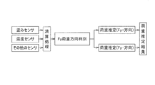
この構成において、前記センサユニット対における2つのセンサユニットのセンサ出力信号の差分を基に、径方向荷重推定手段で、車輪用軸受の径方向に作用する径方向荷重を推定する。また、前記センサユニット対における2つのセンサユニットのセンサ出力信号の和を基に、軸方向荷重推定手段で、車輪用軸受の軸方向に作用する軸方向荷重を推定する。そして、少なくとも1対のセンサユニット対の2つのセンサユニットは、タイヤ接地面に対して上下位置となる前記固定側部材の外径面の上面部と下面部に配置する。このセンサユニット対のセンサの出力信号振幅を基に、軸方向荷重方向判別手段で、前記軸方向荷重の方向を判別する。この場合の荷重推定処理の概略を図17にブロック図で示す。
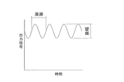
前記センサユニットにおける歪み発生部材の接触固定部を、車輪用軸受における固定側部材の転走面付近に配置すると、車輪の回転に伴ってセンサ出力信号に図18のような正弦波に近い変動が見られる。これは、転動体の通過による歪みの変化が検出されたものである。上記構成では、上下に配置した2つのセンサユニットのセンサ出力信号における振幅値(転動体の公転運動に伴う振動成分)の差分により、軸方向荷重を判別し、軸方向荷重の正負に応じて、それぞれに適した荷重推定パラメータを用いて荷重を演算するので、荷重を感度良く推定できる。
しかし、特許文献2の構成の場合、最適な荷重推定パラメータを選択するために、センサ出力信号の振幅値を算出する必要があり、振幅値を算出できない場合に対応できない。すなわち、回転が静止している状態、あるいは極低速回転状態においては、転動体荷重による信号変化がないか、または非常にゆっくりとした変化しかない状態となる。この場合には、センサ出力信号の変動から振幅の大きさを求めることはできない。
一方、転動体荷重によるセンサ出力信号の振幅値を静止状態においても検出する手段として、転動体荷重の影響を観測するのに十分な領域(転動体の配置ピッチに相当する周方向長さ)に複数のセンサを配置して、歪みの分布を直接測定する手段もある。しかしながら、この場合、センサ個数が増加し、検出回路が複雑化するため、コストアップと信頼性確保が新たな課題となる。
そこで、本発明者等は、センサ付車輪用軸受におけるさらに新たな荷重推定手段として、図19にブロック図で示す構成のものを開発した。この構成では、荷重推定演算式として、変数としてセンサ出力信号の平均値Aのみを用いる式と、変数としてセンサ出力信号の平均値Aと振幅値Bとを用いる式とを用意し、回転速度によって荷重演算処理を切り替えるようにしている。すなわち、通常走行状態では、センサ出力信号の平均値Aと振幅値Bを用いた演算式による荷重推定演算を行い、低速あるいは停止状態においては前記平均値Aだけを用いた演算式による荷重推定演算を行う。この構成の場合、回転速度の判定に、回転速度情報を用いる。
しかし、この構成では、回転速度情報を用いるので、別途回転センサを設けるか、上位のECUなどから回転速度情報を受け取る必要があり、センサや配線が増加してしまうという新たな課題が生じる。
この発明の目的は、追加のセンサ等を設けることなく、簡単な構造で、車速に応じた計算方法の切り替えを実現できて、車輪に加わる荷重の推定精度を向上させることができ、センサや配線の設置スペースを削減してコンパクト化でき、また構成の単純化により信頼性を向上させることができるセンサ付車輪用軸受を提供することである。
この発明のセンサ付車輪用軸受は、複列の転走面が内周に形成された外方部材1と、前記転走面と対向する転走面が外周に形成された内方部材2と、両部材の対向する転走面間に介在した複列の転動体5とを備え、車体に対して車輪を回転自在に支持するセンサ付車輪用軸受であって、前記外方部材1および内方部材2のうちの固定側部材に複数の荷重検出用センサユニット20を設け、前記センサユニット20は、前記固定側部材に接触して固定される2つ以上の接触固定部21aを有する歪み発生部材21、およびこの歪み発生部材21に取付けられてこの歪み発生部材21の歪みを検出する1つ以上のセンサセンサ22,22A,22Bを有し、さらに、前記複数のセンサユニット20のセンサ22,22A,22Bの出力信号から車輪に加わる荷重を推定する荷重推定手段30を設け、前記荷重推定手段30は、前記各センサユニット20における各センサ22の出力信号の一定時間内におけるバラつき量を示す値の総和を算出し、その算出値を評価値として車輪の回転速度が、定められた複数の回転速度領域のいずれに含まれるかを判別する回転速度領域判定部32と、前記各センサユニット20のセンサ22の出力信号を定められた推定演算式に当てはめて車輪用軸受に作用する荷重を演算する荷重推定演算部35と、前記回転速度領域判定部32で判別された回転速度領域に応じて、前記荷重推定演算部35で用いられる推定演算式中のパラメータを切り替える荷重演算条件判断部34とを備えたものである。上記「バラつき量を示す値の総和」は、具体的には、例えば各入力データの標準偏差を合計したものである。
この構成によると、荷重推定手段30において、各センサユニット20のセンサ出力信号のバラつき量を示す値の総和を算出し、その算出値を評価値として回転速度領域判定部32で車輪の回転速度領域を判別する。判別された回転速度領域に応じて前記荷重推定演算部35で用いられる推定演算式のパラメータを荷重演算条件判断部34で切り替える。そのため、車輪の回転速度を検出することなく、センサユニット20のセンサ出力信号から、車輪の回転速度領域に応じた演算処理に切り替えて、車輪に加わる荷重を信頼性良く推定することができる。このため、追加のセンサ等を設けることなく、簡単な構造で、車速に応じた計算方法の切り替えを実現できて、車輪に加わる荷重の推定精度を向上させることができる。また、センサや配線の設置スペースを削減してコンパクト化でき、構成の単純化により信頼性を向上させることができる。
この発明において、前記回転速度領域判定部32は、前記評価値を定められた1つのしきい値と比較して、車輪が、定められた通常の回転速度領域にあるか低速の回転速度領域にあるかを判別するものとしても良い。回転速度領域を2つの領域とするため、車速に応じた計算方法の切り替えが、より簡素な構造で実現できる。
また、この発明において、前記回転速度領域判定部32は、前記評価値を定められた2つ以上のしきい値と比較して、車輪が、定められた3つ以上の回転速度領域のうちいずれの回転速度領域にあるかを判別するものとしても良い。3つ以上の回転速度領域に分けて推定演算式中のパラメータを切り替えることにより、推定精度により優れた荷重の推定を行うことができる。
この発明において、前記荷重演算条件判断部34は、前記回転速度領域判定部32が最低の低速の回転速度領域であると判別したとき、一定時間の経過後に、前記荷重推定演算部35で用いられる推定演算式のパラメータを、定められた規定のパラメータに切り替えるものとしても良い。いわば、最低の低速の回転速度領域であると判別された後の一定時間の経過後に、推定演算式のパラメータを初期値にリセットする。特に、回転速度領域判定部32で軸方向荷重に応じた処理を行う場合に効果的である。ほぼ停止状態の低速であると、軸方向荷重の変化等に応じたパラメータの切り替えができない場合があるが、推定演算式のパラメータを初期値にリセットすることで、低速での荷重推定精度を向上させることができる。
この発明において、前記センサユニット20を3つ以上設け、前記荷重推定手段30は、前記3つ以上のセンサユニット20のセンサの出力信号から、車輪用軸受の径方向に作用する上下方向および左右方向の2つの径方向荷重と、軸方向に作用する一つの軸方向荷重との3方向の荷重を推定するものとしても良い。
この発明において、前記センサユニットを、タイヤ接地面に対して上下位置および左右位置となる前記固定側部材の外径面の上面部、下面部、右面部、および左面部に円周方向90度の位相差で4つ等配しても良い。このように4つのセンサユニット20を配置することで、車輪用軸受に作用する垂直方向荷重Fz、駆動力や制動力となる荷重Fx、軸方向荷重Fyを、より精度良く推定することができる。
このように4つのセンサユニット20を配置した場合に、前記荷重推定演算部35は、前記推定演算式を複数有し、かつこれら複数の推定演算式を選択命令によって選択する演算式選択部35aを有し、前記荷重推定手段30は、上下位置に対向して配置される2つのセンサユニット20のセンサの出力信号の振幅値の差分を用いて、軸方向荷重の方向を判別する方向判別部33を有し、前記荷重演算条件判断部34は、前記荷重推定演算部35で用いられる推定演算式の前記パラメータの切り替えを行うパラメータ切替部34aと、前記方向判別部33の判別結果に対応して前記荷重推定演算部35の前記演算式選択部35aに前記選択命令を与える方向対応命令部34bとを有するものとしても良い。この構成により、車輪用軸受に作用する軸方向荷重の方向に応じた精度のより優れた荷重推定を行うことができる。
この発明において、前記荷重推定手段30は前記各センサユニットにおける各センサの出力信号の一定時間内の平均値と振幅値を算出する前処理部31を有し、前記荷重推定演算部35の推定演算式は、前記平均値のみ、または振幅値のみ、または前記平均値と振幅値の両方の、いずれかを用いて荷重を演算処理するものとしても良い。この場合に、回転速度領域判定部32で判別する回転速度領域が低速領域であるときには、荷重推定演算部35での推定演算式として平均値を用いたものを採用し、回転速度領域が通常の速度領域である場合には、推定演算式として振幅値を用いたもの、あるいは平均値と振幅値を用いたものを採用するのが望ましい。
この発明において、前記センサユニット20は3つ以上の接触固定部21aと2つのセンサ22を有し、隣り合う第1および第2の接触固定部21aの間、および隣り合う第2および第3の接触固定部21aの間に各センサ22をそれぞれ取付け、隣り合う接触固定部21aもしくは隣り合うセンサ22の前記固定側部材の円周方向についての間隔を、転動体5の配列ピッチの{1/2+n(n:整数)}倍とし、前記荷重推定手段30は前記2つのセンサ22の出力信号の和を平均値として用いるものとしても良い。この構成の場合、2つのセンサ22の出力信号は略180度の位相差を有することになり、その平均値は転動体通過による変動成分をキャンセルした値となる。また、振幅値は温度の影響やナックル・フランジ面間などの滑りの影響をより確実に排除した正確なものとなる。
この発明において、前記各センサユニット22に温度センサ36を設け、この温度センサ36の出力信号に基づき、センサユニット22のセンサ出力信号を補正するものとしても良い。この構成の場合、センサユニット22のセンサ出力信号の温度ドリフトを補正することができ、より一層精度良く、荷重の推定が手軽に行える。
請求の範囲および/または明細書および/または図面に開示された少なくとも2つの構成のどのような組合せも、本発明に含まれる。特に、請求の範囲の各請求項の2つ以上のどのような組合せも、本発明に含まれる。
この発明は、添付の図面を参考にした以下の好適な実施形態の説明から、より明瞭に理解されるであろう。しかしながら、実施形態および図面は単なる図示および説明のためのものであり、この発明の範囲を定めるために利用されるべきものではない。この発明の範囲は添付の請求の範囲によって定まる。添付図面において、複数の図面における同一の符号は、同一または相当する部分を示す。
この発明の第1実施形態にかかるセンサ付車輪用軸受の縦断面図とその検出系の概念構成のブロック図とを組み合わせて示す図である。
同センサ付車輪用軸受の外方部材をアウトボード側から見た正面図である。
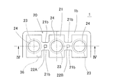
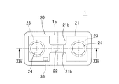
同センサ付車輪用軸受におけるセンサユニットの拡大平面図である。
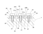
図3におけるIV-IV線断面図である。
センサユニットの他の設置例を示す断面図である。
センサユニットの出力信号に対する転動体位置の影響の説明図である。
荷重推定手段の構成を示すブロック図である。
同荷重推定手段での演算処理動作の説明図である。
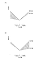
(A)は外方部材外径面上部でのセンサ出力信号の振幅と軸方向荷重の方向との関係を示すグラフ、(B)は同外径面下面部でのセンサ出力信号の振幅と軸方向荷重との関係を示すグラフである。
軸方向荷重の大きさと上下のセンサユニットのセンサ出力信号の差分との関係を示すグラフである。
この発明の第2実施形態にかかるセンサ付車輪用軸受の縦断面図とその検出系の概念構成のブロック図とを組み合わせて示す図である。
同センサ付車輪用軸受の外方部材をアウトボード側から見た正面図である。
同センサ付車輪用軸受におけるセンサユニットの拡大平面図である。
図13におけるXIV -XIV 線断面図である。
センサユニットの他の設置例を示す縦断面図である。
荷重推定手段の構成を示すブロック図である。
提案例における荷重推定処理の流れを示す説明図である。
同提案例におけるセンサ出力信号の波形図である。
他の提案例における荷重推定手段の概略構成を示すブロック図である。
この発明の第1実施形態を図1ないし図10と共に説明する。この実施形態は、第3世代型の内輪回転タイプで、駆動輪支持用の車輪用軸受に適用したものである。なお、この明細書において、車両に取付けた状態で車両の車幅方向の外側寄りとなる側をアウトボード側と呼び、車両の中央寄りとなる側をインボード側と呼ぶ。
このセンサ付車輪用軸受における軸受は、図1に縦断面図で示すように、内周に複列の転走面3を形成した外方部材1と、これら各転走面3に対向する転走面4を外周に形成した内方部材2と、これら外方部材1および内方部材2の転走面3,4間に介在した複列の転動体5とで構成される。この車輪用軸受は、複列のアンギュラ玉軸受型とされていて、転動体5はボールからなり、各列毎に保持器6で保持されている。上記転走面3,4は断面円弧状であり、ボール接触角が背面合わせとなるように形成されている。外方部材1と内方部材2との間の軸受空間の両端は、一対のシール7,8によってそれぞれ密封されている。
外方部材1は固定側部材となるものであって、車体の懸架装置(図示せず)におけるナックル16に取付ける車体取付用フランジ1aを外周に有し、全体が一体の部品とされている。フランジ1aには周方向複数箇所にナックル取付用のねじ孔14が設けられ、インボード側よりナックル16のボルト挿通孔17に挿通したナックルボルト(図示せず)を前記ねじ孔14に螺合することにより、車体取付用フランジ1aがナックル16に取付けられる。
内方部材2は回転側部材となるものであって、車輪取付用のハブフランジ9aを有するハブ輪9と、このハブ輪9の軸部9bのインボード側端の外周に嵌合した内輪10とでなる。これらハブ輪9および内輪10に、前記各列の転走面4が形成されている。ハブ輪9のインボード側端の外周には段差を持って小径となる内輪嵌合面12が設けられ、この内輪嵌合面12に内輪10が嵌合している。ハブ輪9の中心には貫通孔11が設けられている。ハブフランジ9aには、周方向複数箇所にハブボルト(図示せず)の圧入孔15が設けられている。ハブ輪9のハブフランジ9aの根元部付近には、車輪および制動部品(図示せず)を案内する円筒状のパイロット部13がアウトボード側に突出している。
図2は、この車輪用軸受の外方部材1をアウトボード側から見た正面図を示す。なお、図1は、図2におけるI-I線断面図を示す。前記車体取付用フランジ1aは、図2のように、各ねじ孔14が設けられた円周方向部分が他の部分よりも外径側へ突出した突片1aaとされている。
固定側部材である外方部材1の外径面には、4つのセンサユニット20が設けられている。ここでは、これらのセンサユニット20が、タイヤ接地面に対して上下位置および前後位置となる外方部材1の外径面における上面部、下面部、右面部および左面部に設けられている。
これらのセンサユニット20は、図3および図4に拡大平面図および図3におけるIV-IV線断面図として示すように、歪み発生部材21と、この歪み発生部材21に取付けられて歪み発生部材21の歪みを検出する2つの歪みセンサ22A,22Bとでなる。歪み発生部材21は、鋼材等の弾性変形可能な金属製で2mm以下の薄板材からなり、平面概形が全長にわたり均一幅の帯状で両側辺部に切欠き部21bを有する。切欠き部21bの隅部は断面円弧状とされている。また、歪み発生部材21は、外方部材1の外径面にスペーサ23を介して接触固定される3つの接触固定部21aを有する。3つの接触固定部21aは、歪み発生部材21の長手方向に向け1列に並べて配置される。2つの歪みセンサ22A,22Bは、歪み発生部材21における各方向の荷重に対して歪みが大きくなる箇所に貼り付けられる。具体的には、歪み発生部材21の外面側で隣り合う接触固定部21aの間に配置される。
つまり、図4において、左端の接触固定部21aと中央の接触固定部21aとの間に1つの歪みセンサ22Aが配置され、中央の接触固定部21aと右端の接触固定部21aとの間に他の1つの歪みセンサ22Bが配置される。切欠き部21bは、図3のように、歪み発生部材21の両側辺部における前記歪みセンサ22の配置部に対応する2箇所の位置にそれぞれ形成されている。これにより、歪みセンサ22A,22Bは歪み発生部材21の切欠き部21b周辺における長手方向の歪みを検出する。なお、歪み発生部材21は、固定側部材である外方部材1に作用する外力、またはタイヤと路面間に作用する作用力として、想定される最大の力が印加された状態においても、塑性変形しないものとするのが望ましい。塑性変形が生じると、外方部材1の変形がセンサユニット20に伝わらず、歪みの測定に影響を及ぼすからである。
前記センサユニット20は、その歪み発生部材21の3つの接触固定部21aが、外方部材1の軸方向について同じ位置で、かつ各接触固定部21aが互いに円周方向に離れた位置に来るように配置され、これら接触固定部21aがそれぞれスペーサ23を介してボルト24により外方部材1の外径面に固定される。前記各ボルト24は、それぞれ接触固定部21aに設けられた径方向に貫通するボルト挿通孔25からスペーサ23のボルト挿通孔26に挿通し、外方部材1の外周部に設けられたねじ孔27に螺合させる。
このように、スペーサ23を介して外方部材1の外径面に接触固定部21aを固定することにより、薄板状である歪み発生部材21における切欠き部21bを有する各部位が外方部材1の外径面から離れた状態となり、切欠き部21bの周辺の歪み変形が容易となる。接触固定部21aが配置される軸方向位置として、ここでは外方部材1のアウトボード側列の転走面3の周辺となる軸方向位置が選ばれる。ここでいうアウトボード側列の転走面3の周辺とは、インボード側列およびアウトボード側列の転走面3の中間位置からアウトボード側列の転走面3の形成部までの範囲である。外方部材1の外径面へセンサユニット20A,20Bを安定良く固定する上で、外方部材1の外径面における前記スペーサ23が接触固定される箇所には平坦部1bが形成される。
このほか、図5に縦断面図で示すように、外方部材1の外径面における前記歪み発生部材21の3つの接触固定部21aが固定される3箇所の各中間部に溝1cを設けることで、前記スペーサ23を省略し、歪み発生部材21における切欠き部21bが位置する各部位を外方部材1の外径面から離すようにしても良い。
歪みセンサ22としては、種々のものを使用することができる。例えば、歪みセンサ22A,22Bを金属箔ストレインゲージで構成することができる。その場合、通常、歪み発生部材21に対しては接着による固定が行なわれる。また、歪みセンサ22A,22Bを歪み発生部材21上に厚膜抵抗体にて形成することもできる。
センサユニット20の歪みセンサ22A,22Bは、図1に示すように、その出力信号から車輪に加わる荷重を推定する荷重推定手段30に接続される。ここでは、車輪の軸方向に作用する軸方向荷重Fyと、垂直方向に作用する垂直方向荷重Fzと、駆動力や制動力となる前後方向に作用する荷重Fxが推定される。この荷重推定手段30は、図7にブロック図で示すように、前処理部31と、回転速度領域判定部32と、Fy方向判別部33と、荷重演算条件判断部34と、荷重推定演算部35とを有する。
荷重推定手段30の各部の構成の説明の前に、その全体の作用の概要を説明する。まず、外方部材1上の複数の位置に設置した各センサ22の出力信号から、回転に伴って通過する転動体5による変動成分の大きさを演算によってそれぞれ抽出する。
上記の演算処理では、一定時間(T)内のセンサ信号のばらつきを示す値σiとして、標準偏差を求める。このほかに、平均値まわりの二乗平均値や分散値を用いてもよく、これらの値は、一定時間(T)内のデータで転動体5による変動成分の振幅を示す数値として用いることができる。
上記Tの値は、センサ22に要求される応答時間を考慮して設定される。
求められた各センサ信号のばらつき値σiをすべてのセンサ信号について合計して評価値Eとする。
E=Σσi
センサ22は外方部材1の上下左右に配置されており、車輪が回転すると転動体5による変動成分がいずれかのセンサ信号に重畳することになる。
したがって、適当なしきい値Vthを設定することにより、以下のような判断が可能になる。
E>しきい値Vth:回転状態で振幅演算処理が可能→通常走行状態の計算処理を実行。
E<しきい値Vth:ほぼ静止状態で振幅演算処理は不可能→振幅を使用しない計算処理を実行。
この方法では回転速度を検出する必要がなく、歪みセンサ22の信号状態からの演算処理だけで荷重推定の計算方法の切り替えを実現することができる。
上記Tの値は、センサ22に要求される応答時間を考慮して設定される。
求められた各センサ信号のばらつき値σiをすべてのセンサ信号について合計して評価値Eとする。
E=Σσi
センサ22は外方部材1の上下左右に配置されており、車輪が回転すると転動体5による変動成分がいずれかのセンサ信号に重畳することになる。
したがって、適当なしきい値Vthを設定することにより、以下のような判断が可能になる。
E>しきい値Vth:回転状態で振幅演算処理が可能→通常走行状態の計算処理を実行。
E<しきい値Vth:ほぼ静止状態で振幅演算処理は不可能→振幅を使用しない計算処理を実行。
この方法では回転速度を検出する必要がなく、歪みセンサ22の信号状態からの演算処理だけで荷重推定の計算方法の切り替えを実現することができる。
次に、荷重推定手段30を構成する各部の詳細を説明する。前処理部31では、センサユニット20における2つの歪みセンサ22A,22Bの出力信号の和Sumを算出すると共に、予め設定された時間Tにおける各センサ出力信号の平均値Aおよび振幅値Bを算出する。振幅値Bとして、ここでは設定された時間T内のセンサ出力信号のばらつきを示す値であるばらつき値σi(σiは標準偏差あるいは平均値まわりの二乗平均値や分散値)が求められる。前処理31において各センサ出力信号の平均値Aおよび振幅値Bを算出するのに定められた時間Tの大きさは、要求される応答時間を考慮して、設計者等により任意に適切に設定される。
上記バラつき値σiとしては、標準偏差を用いるのが望ましい。車輪の回転速度が高く、演算のために設定された一定時間(T)が、転動体の通過によるセンサ信号の変動分の少なくとも1周期以上を観測できる時間になっていれば、演算によって得られる標準偏差は、転動体の通過による振幅成分と等価なものとなる。その結果、この値を振幅値Bとして荷重の推定演算に用いることができる。一方、車輪の回転速度が低い場合には、時間T内における転動体通過によるセンサの変動成分が観測されなくなり、振幅値に比例した数値ではなくなる。この場合、得られた標準偏差を振幅値Bとして用いることができなくなる。このときの標準偏差は、先の十分な回転速度の場合と比較して小さな値となる。軸受の数箇所に設置された歪みセンサは、印加荷重の状態によってそれぞれ異なった信号を出力するため、転動体の通過による振幅成分は全ての信号に同じように重畳するわけではないが、各センサ信号のばらつき値σiをすべてのセンサ信号について合計した評価値Eは、回転数が低くなると小さな値を示すようになる。
センサユニット20は、外方部材1のアウトボード側列の転走面3の周辺となる軸方向位置に設けられるので、歪みセンサ22A,22Bの出力信号a,bは、図6のようにセンサユニット20の設置部の近傍を通過する転動体5の影響を受ける。また、軸受の停止時においても、歪みセンサ22A,22Bの出力信号a,bは、転動体5の位置の影響を受ける。すなわち、転動体5がセンサユニット20における歪みセンサ22A,22Bに最も近い位置を通過するとき(または、その位置に転動体5があるとき)、歪みセンサ22A,22Bの出力信号a,bの振幅は最大値となり、図6のように転動体5がその位置から遠ざかるにつれて(または、その位置から離れた位置に転動体5があるとき)低下する。軸受回転時には、転動体5は所定の配列ピッチPで前記センサユニット20の設置部の近傍を順次通過するので、歪みセンサ22A,22Bの出力信号a,bは、その振幅が転動体5の配列ピッチPを周期として図6に実線で示すように周期的に変化する正弦波に近い波形となる。
固定側部材である外方部材1の外径面の円周方向に並ぶ3つの接触固定部21aのうち、その配列の両端に位置する2つの接触固定部21aの間隔を、転動体5の配列ピッチPと同一に設定している。この場合、隣り合う接触固定部21aの中間位置にそれぞれ配置される2つの歪みセンサ22A,22Bの間での前記円周方向の間隔は、転動体5の配列ピッチPの略1/2となる。その結果、2つの歪みセンサ22A,22Bの出力信号a,bは略180度の位相差を有することになり、上記した前処理部31で算出する2つの歪みセンサ22A,22Bの出力信号a,bの振幅の和Sumは、転動体5の通過による変動成分をキャンセルしたものとなる。
なお、図6では、接触固定部21aの間隔を、転動体5の配列ピッチPと同一に設定し、隣り合う接触固定部21aの中間位置に各1つの歪みセンサ22A,22Bをそれぞれ配置することで、2つの歪みセンサ22A,22Bの間での前記円周方向の間隔を、転動体5の配列ピッチPの略1/2となるようにした。これとは別に、直接、2つの歪みセンサ22A,22Bの間での前記円周方向の間隔を、転動体5の配列ピッチPの1/2に設定しても良い。この場合に、2つの歪みセンサ22A,22Bの前記円周方向の間隔を、転動体5の配列ピッチPの{1/2+n(n:整数)}倍、またはこれらの値に近似した値としても良い。この場合にも、両歪みセンサ22A,22Bの出力信号a,bの和Sumは転動体5の通過による変動成分をキャンセルした値となる。
図7に示すように、回転速度領域判定部32では、前処理部31で算出された各センサ出力信号のばらつき値σiの総和E=Σσiを評価値として車輪の回転速度の領域を判別する。ここでは、前記評価値Eを予め定められたしきい値Vth(任意に適切な値に設定されるものとする)と比較して、車輪が通常の回転速度領域にあるか低速の回転速度領域にあるかを判別する。このときの回転速度領域判定部32の判定出力Rは2値(0:E<Vth、1:E>Vth)で表され、回転速度が振幅値を求めるのに十分であるかどうかの判断材料とされる。
Fy方向判別部33では、以下のようにして軸方向荷重Fyの方向を判別する。上記したように、車輪用軸受の回転中には、センサユニット20のセンサ出力信号の振幅には、正弦波に近い周期的な変化が生じるが、その振幅値は軸方向荷重(モーメント力)Fyの大きさによって変化する。図9(A)は外方部材1の外径面の上面部に配置されたセンサユニット20のセンサ出力を示し、図9(B)は外方部材1の外径面の下面部に配置されたセンサユニット20のセンサ出力を示している。これらの図において、横軸は軸方向荷重Fyを表し、縦軸は外方部材1の歪み量つまりセンサ出力信号の振幅を表し、最大値および最小値は振幅の最大値および最小値を表す。これらの図から、軸方向荷重Fyが+方向の場合、個々の転動体5の荷重は外方部材1の外径面上面部で小さくなり(つまり振幅の最大値と最小値の差が小さくなる)、外方部材1の外径面下面部で大きくなる(つまり振幅の最大値と最小値の差が大きくなる)ことが分かる。
これに対して、軸方向荷重Fyが-方向の場合には逆に、個々の転動体5の荷重は外方部材1の外径面上面部で大きくなり、外方部材1の外径面下面部で小さくなることが分かる。図10は、これら上下のセンサユニット20のセンサ出力信号の振幅の差分と軸方向荷重Fyの方向の関係をグラフで示している。
そこで、Fy方向判別部33では、外方部材1の外径面上面部および外径面下面部に配置されたセンサユニット20のセンサ出力信号の振幅の上記差分を求め、これらの値を比較することで、軸方向荷重Fyの方向を判別する。すなわち、外方部材1の外径面上面部の振幅の最大値と最小値の差分が小さく、外方部材の外径面下面部のセンサユニット20のセンサ出力信号の振幅の最大値と最小値の差分が大きいとき、Fy方向判別部33では、軸方向荷重Fyの方向が+方向であると判別する。逆に、外方部材1の外径面上面部のセンサユニット20のセンサ出力信号の振幅の最大値と最小値の差分が大きく、外方部材1の外径面下面部のセンサユニット20のセンサ出力信号の振幅の最大値と最小値の差分が小さいとき、Fy方向判別部33では、軸方向荷重Fyの方向が-方向であると判別する。
荷重推定演算部35では、各センサユニット20のセンサ出力信号を定められた推定演算式に当てはめて、車輪用軸受に作用する各荷重Fz,Fx,Fyを演算・推定する。ここでは、その演算に2種類の推定演算式が用いられる。一種類の推定演算式F1は、
F1=M1(c)×[Sum]………(1)
とされ、他の一種類の推定演算式F2は、
F2=M2(c)×[A]+M3(c)×[B]………(2)
とされる。M1(c),M2(c),M3(c)は推定演算式のパラメータであり、演算・推定する各荷重Fz,Fx,Fyごとに異なる。すなわち、推定演算式F1は、前処理部31で算出される和値Sumを変数とし、これにパラメータM1(c)を乗算したものである。和値Sumは車輪の低速状態でも正確に算出できるので、この推定演算式F1は低速時用として用いられる。推定演算式F2は、前処理部31で算出された平均値Aおよび振幅値Bを変数とし、これらにパラメータM2(c),(M3(c)をそれぞれ乗算したものである。平均値Aおよび振幅値Bは、車輪の通常回転状態で正確に算出できるので、この推定演算式F2は通常回転時用として用いられる。荷重推定演算部35は、上記複数の推定演算式F1,F2を選択命令によって選択する演算式選択部35aを有している。
F1=M1(c)×[Sum]………(1)
とされ、他の一種類の推定演算式F2は、
F2=M2(c)×[A]+M3(c)×[B]………(2)
とされる。M1(c),M2(c),M3(c)は推定演算式のパラメータであり、演算・推定する各荷重Fz,Fx,Fyごとに異なる。すなわち、推定演算式F1は、前処理部31で算出される和値Sumを変数とし、これにパラメータM1(c)を乗算したものである。和値Sumは車輪の低速状態でも正確に算出できるので、この推定演算式F1は低速時用として用いられる。推定演算式F2は、前処理部31で算出された平均値Aおよび振幅値Bを変数とし、これらにパラメータM2(c),(M3(c)をそれぞれ乗算したものである。平均値Aおよび振幅値Bは、車輪の通常回転状態で正確に算出できるので、この推定演算式F2は通常回転時用として用いられる。荷重推定演算部35は、上記複数の推定演算式F1,F2を選択命令によって選択する演算式選択部35aを有している。
荷重演算条件判断部34は、パラメータ切替部34aと方向対応命令部34bとを有する。パラメータ切替部34aは、回転速度領域判定部32の出力RとFy方向判別部33の出力sign(Fy)に応じて、荷重推定演算部35における推定演算式F1,F2の各パラメータM1(c),M2(c),M3(c)を切り替え指定する信号Cを生成する機能を持つ。これにより、回転速度領域判定部32の出力RとFy方向判別部33の出力sign(Fy)に応じて、荷重推定演算部35における推定演算式F1,F2の各パラメータM1(c),M2(c),M3(c)が最適な値に切り替えられる。
方向対応命令部34bは、回転速度領域判定部32の出力Rに応じて、荷重推定演算部35における低速時用の推定演算式F1と通常回転時用の推定演算式F2のうちいずれの出力を使用するかを判別する信号FSW(0:低速時用(R=0)、1:通常回転時用(R=1))を生成する機能を持つ。この判別信号FSWは、荷重推定演算部35の方向対応命令部35aに選択命令として入力され、これにより、荷重推定演算部35は、回転速度領域判定部32の出力Rに応じて、回転速度領域に対応した推定演算式の出力を荷重値として選択する。
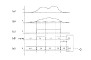
図8の(a)~(e)には、走行状態に応じた荷重推定手段30の具体的な動作の一例を各波形図として示している。これらの波形図は、横軸を時間tとし、縦軸に車輪回転速度v,評価値E,回転速度領域判別出力R,Fy方向判別出力sign(Fy),およびパラメータ切り替え指定信号Cの状態を示すものであって、静止状態から走行を開始して再び静止するまでを示している。同図(a)~(e)におけるパラメータ切り替え指定信号Cの状態表記は、以下のような状態を示すものとする。
C[1]:(R=0,FSW=0,sign(-)):低速状態で、Fy<0の状態用のパラメータを使用。
C[2]:(R=1,FSW=1,sign(-):通常回転状態で、Fy<0の状態用のパラメータを使用。
C[3]:(R=1,FSW=1,sign(+):通常回転状態で、Fy>0の状態用のパラメータを使用。
C[4]:(R=0,FSW=1,sign(+):低速状態で、Fy>0の状態用のパラメータを使用。
C[1]:(R=0,FSW=0,sign(-)):低速状態で、Fy<0の状態用のパラメータを使用。
C[2]:(R=1,FSW=1,sign(-):通常回転状態で、Fy<0の状態用のパラメータを使用。
C[3]:(R=1,FSW=1,sign(+):通常回転状態で、Fy>0の状態用のパラメータを使用。
C[4]:(R=0,FSW=1,sign(+):低速状態で、Fy>0の状態用のパラメータを使用。
すなわち、図8の(a)~(e)の動作例では、以下の判断処理を行っている。
R=1のとき、回転状態で振幅演算処理が可能と判断し、通常走行状態の演算処理を実行(パラメータはFy方向により切り替え、各センサ出力信号の移動平均値Aと振幅値Bを用いて荷重推定する)。
R=0のとき、ほぼ静止状態で振幅演算処理は不可能と判断し、振幅を使用しないで、和値Sumだけを用いた低速時用の演算処理を実行(パラメータは、上下位置のセンサユニット20のセンサ出力信号の振幅差分によるFy方向判別ができないため固定値とし、各センサ出力信号の移動平均値Aと振幅値Bを使用できないため、和値Sumを用いて荷重推定する)。
R=1のとき、回転状態で振幅演算処理が可能と判断し、通常走行状態の演算処理を実行(パラメータはFy方向により切り替え、各センサ出力信号の移動平均値Aと振幅値Bを用いて荷重推定する)。
R=0のとき、ほぼ静止状態で振幅演算処理は不可能と判断し、振幅を使用しないで、和値Sumだけを用いた低速時用の演算処理を実行(パラメータは、上下位置のセンサユニット20のセンサ出力信号の振幅差分によるFy方向判別ができないため固定値とし、各センサ出力信号の移動平均値Aと振幅値Bを使用できないため、和値Sumを用いて荷重推定する)。
図8(c)でR=0となった後は、振幅値を求めるのに十分な回転速度がない状態であるため、Fy方向判別部33の出力sign(Fy)は更新できない状態となり、最後の値が保持されることになる。しかし、同図(d),(e)の一部に符号Qで示したように、ある一定時間t1経過後にFy方向判別部33の出力sign(Fy)を初期値にリセットするような構成としても良い。すなわち、Fy方向判別が不可能になってから、ある一定時間t1までは直前の方向判別値を維持するが、その後は予め決められた初期状態に戻るように処理しても良い。これにより、低速状態が継続した場合には、常に同じパラメータ(この例では同図(e)のC[1])に戻ることになる。そのため、この条件で出現確率の高いパラメータに戻るように設定しておけば、低速での荷重推定精度を安定させることが可能になる。一定時間t1は、任意に定められる。
このほか、上記した判別条件に加えて、検出された軸方向荷重Fyの大きさに応じて、より細かく推定演算式F1、F2のパラメータの切り替えを行っても良い。細かな条件分けにより、センサ出力信号の非線形性による影響を低減し、より荷重推定精度を向上させることができる。また、回転速度領域判定部32の出力Rを0/1の2値ではなく、複数のしきい値を用いて多値となるように構成しても良い。低速回転時におけるパラメータをより細かく条件分けし、走行状態に適した演算処理を行うことで、荷重推定精度を向上させることができる。
また、出力される推定荷重の種類は、上記した3方向の荷重Fx,Fy,Fzに限定するものではなく、荷重推定演算部35における推定演算式F1,F2のパラメータを追加して、ステアモーメントMzや、X軸回りのモーメントMxを演算するように構成することもできる。
さらに、図3のようにセンサユニット20に温度センサ36を取付け、この温度センサ36の検出信号により、各センサ出力信号を補正するようにしても良い。軸受回転による発熱や周辺環境などにより車輪用軸受の温度が変化すると、荷重が変化しなくても、センサユニット20のセンサ出力信号は熱膨張などにより変動するので、検出された荷重に温度の影響が残る。そこで、上記したように温度センサ36の検出信号により各センサ出力信号を補正すると、温度による検出荷重誤差を低減することができる。
車輪のタイヤと路面間に荷重が作用すると、図1に示す車輪用軸受の固定側部材である外方部材1にも荷重が印加されて変形が生じる。ここでは、図4に示すように、センサユニット20における歪み発生部材21の3つの接触固定部21aが、外方部材1に接触固定されているので、外方部材1の歪みが歪み発生部材21に拡大して伝達され易く、その歪みが歪みセンサ22A,22Bで感度良く検出され、その出力信号に生じるヒステリシスも小さくなる。
特に、荷重推定手段30では、前記各センサユニット20のセンサ出力信号のばらつき値σiの総和Σσiを算出し、その算出値を評価値Eとして回転速度領域判定部32で車輪の回転速度領域を判別し、判別された回転速度領域に応じて前記荷重推定演算部35で用いられる推定演算式のパラメータをパラメータ切替部34aで切り替え、また荷重推定演算部35の推定演算式のうち判定された回転速度領域に応じた推定演算式の演算結果を方向対応命令部34bで選択して出力するようにしているので、センサユニット20のセンサ出力信号から、車輪の回転速度領域に応じた演算処理に切り替えて、車輪に加わる荷重を精度良く推定することができる。
また、上記演算処理では、全センサ出力信号からばらつきを求め、それらを機械的に合計した評価値Eのみを用いて、演算方法の切り替えを判断できるため、処理が容易で処理上のオーバヘッドが発生しない。また、評価値Eを用いた演算方法の切り替え判断を、しきい値Vthを用いて行うので、しきい値Vthの設定によって最適な回転速度領域に区分調整が可能になる。また、回転検出用のセンサを設置したり、上位ECUなどから車輪の回転速度などの回転速度情報を入力する必要がなく、センサや配線の設置スペースを削減して構成をコンパクト化できる。構成が単純化されることから、信頼性を向上させることもできる。
図11ないし図16は、この発明の第2実施形態を示す。このセンサ付車輪用軸受では、図1~図10に示す第1実施形態において、各センサユニット20を以下のように構成している。この場合、センサユニット20は、図14に拡大縦断面図に示すように、歪み発生部材21と、この歪み発生部材21に取付けられて歪み発生部材21の歪みを検出する1つの歪みセンサ22とでなる。歪み発生部材21は、外方部材1の外径面にスペーサ23を介して接触固定される2つの接触固定部21aを両端部に有する。このほか、図15に縦断面図で示すように、外方部材1の外径面における前記歪み発生部材21の2つの接触固定部21aが固定される2箇所の各中間部に溝1cを設けることで、前記スペーサ23を省略し、歪み発生部材21における切欠き部21bが位置する部位を外方部材1の外径面から離すようにしても良い。
各センサユニット20には1つの歪みセンサ22が取付けられているだけなので、荷重推定手段30の前処理部31では、先の実施形態での和値Sumは算出されず、各センサ出力信号の平均値Aと振幅値B(時間T内のセンサ出力信号のばらつきを示す標準偏差σi(あるいは分散))とが求められる。また、荷重推定演算部35では一種類の推定演算式F3が用いられる。この推定演算式F3は、先の実施形態における通常回転時用の推定演算式F2と同じ形式のものである。すなわち、平均値Aと振幅値Bを変数とし、これらにパラメータM4(c),M5(c)を乗算したものである。荷重演算条件判断部34はパラメータ切替部34aを有し、Fy方向判別部33の出力sign(Fy)および回転速度領域判定部32の出力Rに応じて、推定演算式F3のパラメータM4(c),M5(c)を切り替える。ここでは、回転速度領域判定部32の出力Rが通常回転領域であることを示すとき、パラメータ切替部34aはパラメータ切り替え指定信号Cとして、前記パラメータM4(c),M5(c)としてゼロでない所定の値に切り替える信号を生成する。
すなわち、通常回転時には前記推定演算式F3は平均値Aと振幅値Bとを変数する推定演算式として用いられる。一方、回転速度領域判定部32の出力Rが低速回転領域であることを示すときには、パラメータ切替部34aはパラメータ切り替え指定信号Cとして、前記パラメータM5(c)をゼロとし、パラメータM4(c)をゼロでない所定の値に切り替える信号を生成する。すなわち、低速時には、前処理部31において振幅値Bを算出できないので、推定演算式F3は平均値Aだけを変数とする推定演算式として用いられ、この推定演算式の演算結果が低速時の荷重値として出力される。
つまり、この第2実施形態でのパラメータ切替部34aは、先の第1実施形態における方向対応命令部34bの機能を兼ねる。なお、この低速時の演算では平均値Aだけを用いるために演算誤差が大きくなるので、低速時の演算モードになっていることを示す信号を別途出力するものとしてもよい。この信号の状態に応じて、信号を利用する制御回路などにおける処理方法を切り替えることにより、検出誤差の影響を低減することが可能になる。
なお、上記した各実施形態では,外方部材1が固定側部材である場合につき説明したが、この発明は、内方部材が固定側部材である車輪用軸受にも適用することができ、その場合、センサユニット20は内方部材の内周となる周面に設ける。
また、これらの実施形態では第3世代型の車輪用軸受に適用した場合につき説明したが、この発明は、軸受部分とハブとが互いに独立した部品となる第1または第2世代型の車輪用軸受や、内方部材の一部が等速ジョイントの外輪で構成される第4世代型の車輪用軸受にも適用することができる。また、このセンサ付車輪用軸受は、従動輪用の車輪用軸受にも適用でき、さらに各世代形式のテーパころタイプの車輪用軸受にも適用することができる。
以上のとおり、図面を参照しながら好適な実施形態を説明したが、当業者であれば、本件明細書を見て、自明な範囲内で種々の変更および修正を容易に想定するであろう。したがって、そのような変更および修正は、請求の範囲から定まる発明の範囲内のものと解釈される。
1…外方部材
2…内方部材
3,4…転走面
5…転動体
20…センサユニット
21…歪み発生部材
21a…接触固定部
22,22A,22B…歪みセンサ
30…荷重推定手段
31…前処理部
32…回転速度領域判定部
33…Fy方向判別部
34…荷重演算条件判断部
34a…パラメータ切替部
34b…方向対応命令部
35…荷重推定演算部
35a…演算式選択部
36…温度センサ
2…内方部材
3,4…転走面
5…転動体
20…センサユニット
21…歪み発生部材
21a…接触固定部
22,22A,22B…歪みセンサ
30…荷重推定手段
31…前処理部
32…回転速度領域判定部
33…Fy方向判別部
34…荷重演算条件判断部
34a…パラメータ切替部
34b…方向対応命令部
35…荷重推定演算部
35a…演算式選択部
36…温度センサ
Claims (10)
- 複列の転走面が内周に形成された外方部材と、
前記転走面と対向する転走面が外周に形成された内方部材と、両部材の対向する転走面間に介在した複列の転動体とを備え、車体に対して車輪を回転自在に支持するセンサ付車輪用軸受であって、
前記外方部材および内方部材のうちの固定側部材に複数の荷重検出用センサユニットを設け、前記センサユニットは、前記固定側部材に接触して固定される2つ以上の接触固定部を有する歪み発生部材、およびこの歪み発生部材に取付けられてこの歪み発生部材の歪みを検出する1つ以上のセンサを有し、
さらに、前記複数のセンサユニットのセンサの出力信号から車輪に加わる荷重を推定する荷重推定手段を設け、
前記荷重推定手段は、前記各センサユニットにおける各センサの出力信号の一定時間内におけるバラつき量を示す値の総和を算出し、その算出値を評価値として車輪の回転速度が、定められた複数の回転速度領域のいずれに含まれるかを判別する回転速度領域判別部と、前記各センサユニットのセンサの出力信号を定められた推定演算式に当てはめて車輪用軸受に作用する荷重を演算する荷重推定演算部と、前記回転速度領域判別部で判別された回転速度領域に応じて、前記荷重推定演算部で用いられる推定演算式中のパラメータを切り替える荷重演算条件判断部とを備えるセンサ付車輪用軸受。 - 請求項1において、前記回転速度領域判別部は、前記評価値を定められた1つのしきい値と比較して、車輪が、定められた通常の回転速度領域にあるか低速の回転速度領域にあるかを判別するセンサ付車輪用軸受。
- 請求項1において、前記回転速度領域判別部は、前記評価値を定められた2つ以上のしきい値と比較して、車輪が、定められた3つ以上の回転速度領域のうちいずれの回転速度領域にあるかを判別するセンサ付車輪用軸受。
- 請求項1において、前記荷重演算条件判断部は、前記回転速度領域判別部が最低の低速の回転速度領域であると判別したとき、一定時間の経過後に、前記荷重推定演算部で用いられる推定演算式のパラメータを、定められた規定のパラメータに切り替えるセンサ付車輪用軸受。
- 請求項1において、前記センサユニットを3つ以上設け、前記荷重推定手段は、前記3つ以上のセンサユニットのセンサの出力信号から、車輪用軸受の径方向に作用する上下方向および左右方向の2つの径方向荷重と、軸方向に作用する一つの軸方向荷重との3方向の荷重を推定するものとしたセンサ付車輪用軸受。
- 請求項1において、前記センサユニットを、タイヤ接地面に対して上下位置および左右位置となる前記固定側部材の外径面の上面部、下面部、右面部、および左面部に円周方向90度の位相差で4つ等配したセンサ付車輪用軸受。
- 請求項6において、前記荷重推定演算部は、前記推定演算式を複数有し、かつこれら複数の推定演算式を選択命令によって選択する演算式選択部を有し、前記荷重推定手段は、上下位置に対向して配置される2つのセンサユニットのセンサの出力信号の振幅値の差分を用いて、軸方向荷重の方向を判別する方向判別部を有し、前記荷重演算条件判断部は、前記荷重推定演算部で用いられる推定演算式の前記パラメータの切り替えを行うパラメータ切替部と、前記方向判別部の判別結果に対応して前記荷重推定演算部の前記方向対応命令部に前記選択命令を与える方向対応命令部とを有するセンサ付車輪用軸受。
- 請求項1において、前記荷重推定手段は前記各センサユニットにおける各センサの出力信号の一定時間内の平均値と振幅値を算出する前処理部を有し、前記荷重推定演算部の推定演算式は、前記平均値のみ、または振幅値のみ、または前記平均値と振幅値の両方の、いずれかを用いて荷重を演算処理するセンサ付車輪用軸受。
- 請求項8において、前記センサユニットは3つ以上の接触固定部と2つのセンサを有し、隣り合う第1および第2の接触固定部の間、および隣り合う第2および第3の接触固定部の間に各センサをそれぞれ取付け、隣り合う接触固定部もしくは隣り合うセンサの前記固定側部材の円周方向についての間隔を、転動体の配列ピッチの{1/2+n(n:整数)}倍とし、前記荷重推定手段は前記2つのセンサの出力信号の和を平均値として用いるものとしたセンサ付車輪用軸受。
- 請求項1において、前記各センサユニットに温度センサを設け、この温度センサの出力信号に基づき、センサユニットのセンサの出力信号を補正するものとしたセンサ付車輪用軸受。
Applications Claiming Priority (2)
| Application Number | Priority Date | Filing Date | Title |
|---|---|---|---|
| JP2010-180098 | 2010-08-11 | ||
| JP2010180098A JP5638310B2 (ja) | 2010-08-11 | 2010-08-11 | センサ付車輪用軸受 |
Publications (1)
| Publication Number | Publication Date |
|---|---|
| WO2012020654A1 true WO2012020654A1 (ja) | 2012-02-16 |
Family
ID=45567623
Family Applications (1)
| Application Number | Title | Priority Date | Filing Date |
|---|---|---|---|
| PCT/JP2011/067463 Ceased WO2012020654A1 (ja) | 2010-08-11 | 2011-07-29 | センサ付車輪用軸受 |
Country Status (2)
| Country | Link |
|---|---|
| JP (1) | JP5638310B2 (ja) |
| WO (1) | WO2012020654A1 (ja) |
Cited By (2)
| Publication number | Priority date | Publication date | Assignee | Title |
|---|---|---|---|---|
| CN109790870A (zh) * | 2016-09-16 | 2019-05-21 | 株式会社捷太格特 | 用于制造毂单元的方法 |
| US11585383B2 (en) * | 2018-09-17 | 2023-02-21 | Iljin Global Co., Ltd | Sensing apparatus for vehicle, wheel bearing assembly, and method for manufacturing sensing apparatus for vehicle |
Families Citing this family (2)
| Publication number | Priority date | Publication date | Assignee | Title |
|---|---|---|---|---|
| JP2014115079A (ja) * | 2012-12-06 | 2014-06-26 | Ntn Corp | センサ付車輪用軸受装置 |
| JP2015225005A (ja) * | 2014-05-29 | 2015-12-14 | Ntn株式会社 | センサ付車輪用軸受 |
Citations (4)
| Publication number | Priority date | Publication date | Assignee | Title |
|---|---|---|---|---|
| JPH01206113A (ja) * | 1988-02-12 | 1989-08-18 | Agency Of Ind Science & Technol | センサー付き転がり軸受 |
| JP2009198231A (ja) * | 2008-02-20 | 2009-09-03 | Meidensha Corp | 回転体の位相・速度検出装置 |
| JP2010043901A (ja) * | 2008-08-11 | 2010-02-25 | Ntn Corp | センサ付車輪用軸受 |
| JP2010096565A (ja) * | 2008-10-15 | 2010-04-30 | Ntn Corp | センサ付車輪用軸受 |
-
2010
- 2010-08-11 JP JP2010180098A patent/JP5638310B2/ja not_active Expired - Fee Related
-
2011
- 2011-07-29 WO PCT/JP2011/067463 patent/WO2012020654A1/ja not_active Ceased
Patent Citations (4)
| Publication number | Priority date | Publication date | Assignee | Title |
|---|---|---|---|---|
| JPH01206113A (ja) * | 1988-02-12 | 1989-08-18 | Agency Of Ind Science & Technol | センサー付き転がり軸受 |
| JP2009198231A (ja) * | 2008-02-20 | 2009-09-03 | Meidensha Corp | 回転体の位相・速度検出装置 |
| JP2010043901A (ja) * | 2008-08-11 | 2010-02-25 | Ntn Corp | センサ付車輪用軸受 |
| JP2010096565A (ja) * | 2008-10-15 | 2010-04-30 | Ntn Corp | センサ付車輪用軸受 |
Cited By (3)
| Publication number | Priority date | Publication date | Assignee | Title |
|---|---|---|---|---|
| CN109790870A (zh) * | 2016-09-16 | 2019-05-21 | 株式会社捷太格特 | 用于制造毂单元的方法 |
| US10962061B2 (en) | 2016-09-16 | 2021-03-30 | Jtekt Corporation | Method for manufacturing hub unit |
| US11585383B2 (en) * | 2018-09-17 | 2023-02-21 | Iljin Global Co., Ltd | Sensing apparatus for vehicle, wheel bearing assembly, and method for manufacturing sensing apparatus for vehicle |
Also Published As
| Publication number | Publication date |
|---|---|
| JP5638310B2 (ja) | 2014-12-10 |
| JP2012037471A (ja) | 2012-02-23 |
Similar Documents
| Publication | Publication Date | Title |
|---|---|---|
| JP5274343B2 (ja) | センサ付車輪用軸受 | |
| WO2010055636A1 (ja) | センサ付車輪用軸受 | |
| CN103210291B (zh) | 带有传感器的车轮用轴承 | |
| JP5143039B2 (ja) | センサ付車輪用軸受 | |
| JP5638310B2 (ja) | センサ付車輪用軸受 | |
| JP5100567B2 (ja) | センサ付車輪用軸受 | |
| WO2012033018A1 (ja) | センサ付車輪用軸受 | |
| EP2930486A1 (en) | Wheel bearing device with attached sensor | |
| JP5268756B2 (ja) | センサ付車輪用軸受 | |
| JP5063270B2 (ja) | センサ付車輪用軸受 | |
| WO2009098843A1 (ja) | センサ付車輪用軸受 | |
| JP5094457B2 (ja) | センサ付車輪用軸受 | |
| JP2010230406A (ja) | センサ付車輪用軸受 | |
| JP5268755B2 (ja) | センサ付車輪用軸受 | |
| JP5646291B2 (ja) | センサ付車輪用軸受 | |
| JP5553731B2 (ja) | センサ付車輪用軸受 | |
| JP5142683B2 (ja) | センサ付車輪用軸受 | |
| JP2010127376A (ja) | センサ付車輪用軸受 | |
| JP5882699B2 (ja) | センサ付車輪用軸受装置 | |
| JP5489929B2 (ja) | センサ付車輪用軸受 | |
| JP5864331B2 (ja) | センサ付車輪用軸受装置 | |
| JP5731308B2 (ja) | センサ付車輪用軸受 | |
| JP5996297B2 (ja) | センサ付車輪用軸受装置 | |
| JP2010121745A (ja) | センサ付車輪用軸受 | |
| JP5224805B2 (ja) | センサ付車輪用軸受 |
Legal Events
| Date | Code | Title | Description |
|---|---|---|---|
| 121 | Ep: the epo has been informed by wipo that ep was designated in this application |
Ref document number: 11816320 Country of ref document: EP Kind code of ref document: A1 |
|
| NENP | Non-entry into the national phase |
Ref country code: DE |
|
| 122 | Ep: pct application non-entry in european phase |
Ref document number: 11816320 Country of ref document: EP Kind code of ref document: A1 |