WO2012018012A1 - 構造物支持構造の施工方法、及びその施工方法を用いた太陽光発電システム - Google Patents
構造物支持構造の施工方法、及びその施工方法を用いた太陽光発電システム Download PDFInfo
- Publication number
- WO2012018012A1 WO2012018012A1 PCT/JP2011/067672 JP2011067672W WO2012018012A1 WO 2012018012 A1 WO2012018012 A1 WO 2012018012A1 JP 2011067672 W JP2011067672 W JP 2011067672W WO 2012018012 A1 WO2012018012 A1 WO 2012018012A1
- Authority
- WO
- WIPO (PCT)
- Prior art keywords
- bolt
- solar cell
- cell module
- support
- fixing
- Prior art date
- Legal status (The legal status is an assumption and is not a legal conclusion. Google has not performed a legal analysis and makes no representation as to the accuracy of the status listed.)
- Ceased
Links
Images






Classifications
-
- H—ELECTRICITY
- H02—GENERATION; CONVERSION OR DISTRIBUTION OF ELECTRIC POWER
- H02S—GENERATION OF ELECTRIC POWER BY CONVERSION OF INFRARED RADIATION, VISIBLE LIGHT OR ULTRAVIOLET LIGHT, e.g. USING PHOTOVOLTAIC [PV] MODULES
- H02S20/00—Supporting structures for PV modules
- H02S20/20—Supporting structures directly fixed to an immovable object
- H02S20/22—Supporting structures directly fixed to an immovable object specially adapted for buildings
- H02S20/23—Supporting structures directly fixed to an immovable object specially adapted for buildings specially adapted for roof structures
-
- F—MECHANICAL ENGINEERING; LIGHTING; HEATING; WEAPONS; BLASTING
- F24—HEATING; RANGES; VENTILATING
- F24S—SOLAR HEAT COLLECTORS; SOLAR HEAT SYSTEMS
- F24S25/00—Arrangement of stationary mountings or supports for solar heat collector modules
- F24S25/10—Arrangement of stationary mountings or supports for solar heat collector modules extending in directions away from a supporting surface
- F24S25/12—Arrangement of stationary mountings or supports for solar heat collector modules extending in directions away from a supporting surface using posts in combination with upper profiles
-
- F—MECHANICAL ENGINEERING; LIGHTING; HEATING; WEAPONS; BLASTING
- F24—HEATING; RANGES; VENTILATING
- F24S—SOLAR HEAT COLLECTORS; SOLAR HEAT SYSTEMS
- F24S25/00—Arrangement of stationary mountings or supports for solar heat collector modules
- F24S25/60—Fixation means, e.g. fasteners, specially adapted for supporting solar heat collector modules
- F24S25/63—Fixation means, e.g. fasteners, specially adapted for supporting solar heat collector modules for fixing modules or their peripheral frames to supporting elements
- F24S25/634—Clamps; Clips
- F24S25/636—Clamps; Clips clamping by screw-threaded elements
-
- H—ELECTRICITY
- H02—GENERATION; CONVERSION OR DISTRIBUTION OF ELECTRIC POWER
- H02S—GENERATION OF ELECTRIC POWER BY CONVERSION OF INFRARED RADIATION, VISIBLE LIGHT OR ULTRAVIOLET LIGHT, e.g. USING PHOTOVOLTAIC [PV] MODULES
- H02S20/00—Supporting structures for PV modules
- H02S20/30—Supporting structures being movable or adjustable, e.g. for angle adjustment
-
- F—MECHANICAL ENGINEERING; LIGHTING; HEATING; WEAPONS; BLASTING
- F16—ENGINEERING ELEMENTS AND UNITS; GENERAL MEASURES FOR PRODUCING AND MAINTAINING EFFECTIVE FUNCTIONING OF MACHINES OR INSTALLATIONS; THERMAL INSULATION IN GENERAL
- F16B—DEVICES FOR FASTENING OR SECURING CONSTRUCTIONAL ELEMENTS OR MACHINE PARTS TOGETHER, e.g. NAILS, BOLTS, CIRCLIPS, CLAMPS, CLIPS OR WEDGES; JOINTS OR JOINTING
- F16B5/00—Joining sheets or plates, e.g. panels, to one another or to strips or bars parallel to them
- F16B5/0004—Joining sheets, plates or panels in abutting relationship
- F16B5/0056—Joining sheets, plates or panels in abutting relationship by moving the sheets, plates or panels or the interlocking key perpendicular to the main plane
- F16B5/0068—Joining sheets, plates or panels in abutting relationship by moving the sheets, plates or panels or the interlocking key perpendicular to the main plane and using I-shaped clamps with flanges moving towards each other
- F16B5/0072—Joining sheets, plates or panels in abutting relationship by moving the sheets, plates or panels or the interlocking key perpendicular to the main plane and using I-shaped clamps with flanges moving towards each other and using screw-thread
-
- F—MECHANICAL ENGINEERING; LIGHTING; HEATING; WEAPONS; BLASTING
- F24—HEATING; RANGES; VENTILATING
- F24S—SOLAR HEAT COLLECTORS; SOLAR HEAT SYSTEMS
- F24S25/00—Arrangement of stationary mountings or supports for solar heat collector modules
- F24S25/60—Fixation means, e.g. fasteners, specially adapted for supporting solar heat collector modules
- F24S2025/6006—Fixation means, e.g. fasteners, specially adapted for supporting solar heat collector modules by using threaded elements, e.g. stud bolts
-
- Y—GENERAL TAGGING OF NEW TECHNOLOGICAL DEVELOPMENTS; GENERAL TAGGING OF CROSS-SECTIONAL TECHNOLOGIES SPANNING OVER SEVERAL SECTIONS OF THE IPC; TECHNICAL SUBJECTS COVERED BY FORMER USPC CROSS-REFERENCE ART COLLECTIONS [XRACs] AND DIGESTS
- Y02—TECHNOLOGIES OR APPLICATIONS FOR MITIGATION OR ADAPTATION AGAINST CLIMATE CHANGE
- Y02B—CLIMATE CHANGE MITIGATION TECHNOLOGIES RELATED TO BUILDINGS, e.g. HOUSING, HOUSE APPLIANCES OR RELATED END-USER APPLICATIONS
- Y02B10/00—Integration of renewable energy sources in buildings
- Y02B10/10—Photovoltaic [PV]
-
- Y—GENERAL TAGGING OF NEW TECHNOLOGICAL DEVELOPMENTS; GENERAL TAGGING OF CROSS-SECTIONAL TECHNOLOGIES SPANNING OVER SEVERAL SECTIONS OF THE IPC; TECHNICAL SUBJECTS COVERED BY FORMER USPC CROSS-REFERENCE ART COLLECTIONS [XRACs] AND DIGESTS
- Y02—TECHNOLOGIES OR APPLICATIONS FOR MITIGATION OR ADAPTATION AGAINST CLIMATE CHANGE
- Y02B—CLIMATE CHANGE MITIGATION TECHNOLOGIES RELATED TO BUILDINGS, e.g. HOUSING, HOUSE APPLIANCES OR RELATED END-USER APPLICATIONS
- Y02B10/00—Integration of renewable energy sources in buildings
- Y02B10/20—Solar thermal
-
- Y—GENERAL TAGGING OF NEW TECHNOLOGICAL DEVELOPMENTS; GENERAL TAGGING OF CROSS-SECTIONAL TECHNOLOGIES SPANNING OVER SEVERAL SECTIONS OF THE IPC; TECHNICAL SUBJECTS COVERED BY FORMER USPC CROSS-REFERENCE ART COLLECTIONS [XRACs] AND DIGESTS
- Y02—TECHNOLOGIES OR APPLICATIONS FOR MITIGATION OR ADAPTATION AGAINST CLIMATE CHANGE
- Y02E—REDUCTION OF GREENHOUSE GAS [GHG] EMISSIONS, RELATED TO ENERGY GENERATION, TRANSMISSION OR DISTRIBUTION
- Y02E10/00—Energy generation through renewable energy sources
- Y02E10/40—Solar thermal energy, e.g. solar towers
- Y02E10/47—Mountings or tracking
-
- Y—GENERAL TAGGING OF NEW TECHNOLOGICAL DEVELOPMENTS; GENERAL TAGGING OF CROSS-SECTIONAL TECHNOLOGIES SPANNING OVER SEVERAL SECTIONS OF THE IPC; TECHNICAL SUBJECTS COVERED BY FORMER USPC CROSS-REFERENCE ART COLLECTIONS [XRACs] AND DIGESTS
- Y02—TECHNOLOGIES OR APPLICATIONS FOR MITIGATION OR ADAPTATION AGAINST CLIMATE CHANGE
- Y02E—REDUCTION OF GREENHOUSE GAS [GHG] EMISSIONS, RELATED TO ENERGY GENERATION, TRANSMISSION OR DISTRIBUTION
- Y02E10/00—Energy generation through renewable energy sources
- Y02E10/50—Photovoltaic [PV] energy
Definitions
- the present invention relates to a method for constructing a structure support structure for supporting a structure such as a solar cell module, and a photovoltaic power generation system using the construction method.
- a structure mount there is a structure in which a plurality of crosspieces are fixed in parallel and a plurality of solar cell modules are bridged between the crosspieces to support each solar cell module.
- Patent Document 1 in order to fix the end of the solar cell module on the crosspiece, the clamp plate is placed on the end of the solar cell module, and the bolt is supported on the crosspiece side through the hole of the clamp plate.
- a configuration is disclosed in which a solar cell module is fixed by being screwed into a nut and clamped between a clamp plate and a crosspiece.
- Patent Document 2 discloses a configuration in which a bolt is protruded downward from a crosspiece between each solar cell module, and a nut is screwed into a lower end of the bolt and tightened.
- the nut tightening operation can be performed from below the solar cell module, and even if the solar cell module is installed at a high position, the nut tightening operation is easy and less dangerous.
- the present invention has been made in view of the above-described conventional problems, and makes it easy to perform bolt tightening work regardless of directionality, without increasing the number of parts, and improving work efficiency. It is an object of the present invention to provide a construction method for a possible structure support structure and a photovoltaic power generation system using the construction method.
- the construction method of the structure support structure of the present invention is such that the structure is placed on a base, a fixing member is disposed on an end of the structure, and the fixing member is penetrated.
- the bolt in the step of temporarily fixing, the bolt is inserted and screwed in from the base side base side or the fixing member side, and the tip of the bolt is protruded on the side opposite to the insertion side. . Therefore, it is necessary to screw the bolt from the insertion side to the opposite side.
- the bolt in the fastening process, the bolt is fastened by rotating the tip of the bolt using a tool that engages with the protruding tip of the bolt. Even if there is no, the bolt fastening operation can be easily performed on the side opposite to the bolt insertion side. For this reason, parts, such as a nut and a washer, do not increase, work efficiency can be improved, and work safety can be secured.
- the bolt is temporarily fixed to the bolt through a coil spring in the temporary fixing step.
- the bolt in the step of temporarily fixing, the bolt is inserted and screwed from the fixing member side to the base side, and a tip end portion of the bolt is below the base.
- the tip of the bolt projecting to the lower side of the base is engaged and rotated by the tool.
- the bolt in the temporarily fixing step, the bolt is screwed into the base side, and the tip of the bolt is protruded below the base. Therefore, it is necessary to screw the bolt downward from above.
- the tool is engaged with the tip of the bolt protruding downward, and the bolt is rotated by rotating the tip of the bolt. After the structure is arranged, Even if there is no empty space, the bolt can be fastened from below the structure. For this reason, parts, such as a nut and a washer, do not increase, work efficiency can be improved, and work safety can be secured.
- the method includes a step of sequentially laying and arranging a plurality of the structures between a plurality of parallel bars that serve as the base, Each time the structure is arranged between the bars, it is preferable to use the adjacent empty space before the next structure is arranged.
- the structure may be a solar cell module.
- a photovoltaic power generation system using the construction method for the structure support structure according to each of the above solutions is also within the scope of the technical idea of the present invention. That is, the solar power generation system according to the present invention is configured such that the end portion of the solar cell module is sandwiched between the base and the fixing member.
- the bolt fastening operation can be easily performed on the side opposite to the bolt insertion side. For this reason, parts, such as a nut and a washer, do not increase, work efficiency can be improved, and work safety can be secured.
- FIG. 1 is a perspective view showing a photovoltaic power generation system to which a construction method for a structure support structure according to an embodiment of the present invention is applied.
- FIG. 2 is a perspective view showing the solar cell module.
- FIG. 3 is a side view showing a truss structure including struts, two arms, a vertical rail, and the like.
- FIG. 4 is a perspective view showing a first support fitting for connecting and fixing the solar cell module to the middle horizontal rail.
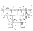
- FIG. 5 is a cross-sectional view showing a state in which two first support fittings are attached to a cross rail.
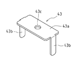
- FIG. 6 is a perspective view showing a fixing fitting disposed on the light receiving surface side of the solar cell module.
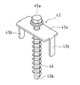
- FIG. 7 is a perspective view showing a state in which the fixing metal fitting, the bolt, and the coil spring of FIG. 6 are combined.
- FIG. 8 is a partially enlarged perspective view showing a state in which each solar cell module is attached to the middle horizontal rail using the first support bracket and the fixing bracket as viewed from above.
- FIG. 9 is a partially enlarged perspective view showing a state in which each solar cell module is attached to the middle horizontal rail using the first support bracket and the fixing bracket as viewed from below.
- FIG. 10 is a partially enlarged perspective view showing a state in which the protruding pieces of the fixing bracket are inserted between the frame members of the solar cell modules adjacent to the left and right.
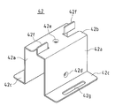
- FIG. 11 is a perspective view showing a second support fitting for connecting and fixing the solar cell module to the upper and lower horizontal rails.
- FIG. 12 is a cross-sectional view showing a state in which the second support fitting is attached to the cross rail.
- FIG. 13A is a plan view showing a state in which two left and right solar cell modules are attached to the upper and lower horizontal rails using the second support bracket and the fixing bracket, and
- FIG. 14 is a cross-sectional view taken along the line BB in FIG.
- FIGS. 14 (a) to 14 (d) are diagrams showing a procedure for mounting the solar cell module on the horizontal rail.
- FIG. 15 is a diagram illustrating a process of fixing the solar cell module on the horizontal rail.
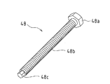
- FIG. 16 is a perspective view showing a modified example of the bolt in the structure support structure according to the present invention.
- FIG. 1 is a perspective view showing a photovoltaic power generation system to which a construction support structure construction method according to an embodiment of the present invention is applied.
- This solar power generation system is premised on application to a power plant and includes a large number of solar cell modules.
- a plurality of support pillars 11 are driven into the ground with a space between each other and protruded, and a vertical beam 14 is inclined and connected to the upper end portion of each support pillar 11.
- Two arms 12 and 13 are bridged and connected between each of the vertical bars 14 and the vertical bars 14 are supported on the upper ends of the columns 11.
- the vertical bars 14 are arranged in parallel with a space between each other, and the three horizontal bars 15 serving as the base of the solar cell module are arranged so as to be orthogonal to the vertical bars 14.
- a plurality of solar cell modules 2 are spanned between each horizontal beam 15 and inclined, and both ends of each solar cell module 2 are fixedly supported on each horizontal beam 15.
- the vertical beam 14 is provided with a pair of arm connecting members 16 that are separated from each other in the longitudinal direction of the vertical beam 14 and protrude below the vertical beam 14.
- the arms 12 and 13 are connected and supported on the downward projecting portions of the arm connecting members 16.
- Each arm bracket 22 is interposed between the body of the column 11 and the ends of the two arms 12 and 13, and the ends of the arms 12 and 13 are connected via the arm brackets 22.
- the body portion of the support column 11 is supported between the arm brackets 22.
- a crosspiece bracket 21 is interposed between the upper end portion of the support column 11 and the vertical beam 14, and the upper end portion of the support column 11 and the vertical beam 14 are connected by the crosspiece bracket 21.
- a plurality of solar cell modules 2 are mounted in a horizontal row between the lower horizontal beam 15 and the middle horizontal beam 15, and a plurality of solar cell modules are also interposed between the middle horizontal beam 15 and the upper horizontal beam 15. 2 are mounted in a horizontal row. Accordingly, a plurality of solar cell modules 2 are mounted in two rows on the three horizontal rails 15. In addition, four or six solar cell modules 2 are allocated between two vertical bars 14 adjacent to the left and right.
- the direction in which the columns 11 are arranged is the X direction (left-right direction), and the direction orthogonal to the X direction is the Y direction (front-rear direction).
- FIG. 2 is a perspective view showing the solar cell module 2.
- the solar cell module 2 includes a solar cell panel 3 that photoelectrically converts sunlight, and a frame member 4 that borders and holds the solar cell panel 3.
- the frame member 4 is made of an aluminum material, and is for securing the strength of the solar cell module 2 itself or protecting the solar cell panel 3.
- FIG. 3 is a side view showing a truss structure including a support column 11, two arms 12 and 13, a vertical beam 14, and the like.
- the central portion of the vertical beam 14 is connected to the upper end portion 11d of the column 11 via the beam bracket 21, and one end portion of the arm 12 is connected to the portion near the tip of the vertical beam 14.
- the arm 13 is connected via the arm connecting member 16, one end of the arm 13 is connected to the portion near the rear end of the vertical rail 14 via the arm connecting member 16, and the other end of each arm 12, 13 is connected to 2 It connects to the trunk
- Such a truss structure including the support columns 11, the two arms 12 and 13, and the vertical beam 14 increases the support strength of the solar cell module 2.
- a plurality of support columns 11 are projected with a space between each other, and the truss structure of FIG. 3 is constructed for each support column 11 so that the plurality of vertical beams 14 are arranged in parallel at regular intervals.
- the three horizontal bars 15 are arranged so as to be orthogonal to the vertical bars 14, and the horizontal bars 15 are fixed on the vertical bars 14.
- the middle horizontal beam 15 supports the ends of the upper and lower solar cell modules 2, and the upper and lower horizontal beams 15 support the edge of the upper or lower solar cell module 2. is doing. For this reason, the support structure of the solar cell module 2 is different between the middle horizontal rail 15 and the upper and lower horizontal rails 15, and the first and second support fittings are used properly.
- FIG. 4 is a perspective view showing a first support fitting for connecting and fixing the solar cell module 2 to the middle horizontal rail 15.
- the first support fitting 41 has a side plate 41a, a main plate 41b bent at the upper edge of the side plate 41a, and a bottom plate 41c bent at the lower edge of the side plate 41a.
- the main plate 41b is formed with projections 41d that are bent and raised at both corners of the main plate 41b.
- Each protrusion 41d draws an arc that is curved so as to go through both corners of the main plate 41b when viewed from above.
- a screw hole 41e is formed in the approximate center of the main plate 41b.
- a perforation 41f is formed in the side plate 41a, a C-shaped cut is formed in the side plate 41a, and an inner portion of this cut is raised to form an engagement piece 41g.
- the height of the side plate 41a is substantially equal to the height of the side plate 15a of the horizontal rail 15.
- the two first support fittings 41 are overlapped on the side plates 15 a of the middle horizontal rail 15, and the engagement pieces 41 g of the side plates 41 a of the first support fittings 41 are connected to the side plates 15 a of the horizontal rail 15.
- the first support fittings 41 are temporarily fixed by engaging with slits (not shown).
- the main plate 41 b of each first support fitting 41 protrudes outward from the horizontal beam 15, and each protruding piece 41 d of each first support fitting 41 protrudes above the main plate 15 b of the horizontal beam 15.
- the pipe 25 is inserted between the side plates 15a of the horizontal rail 15 to drill the pipe 25, the side plates 15a of the horizontal rail 15 (not shown), and the side plates 41a of the first support fittings 41. 41f is aligned, the bolt 26 is passed through the pipe 25, the perforations of the side plates 15a of the crosspieces 15, the perforations 41f of the side plates 41a of the first support fittings 41, and the washers, and the nuts 27 are screwed into one end of the bolts 26.
- the first support fittings 41 are fixed to the middle horizontal rail 15.
- FIG. 6 is a perspective view showing a fixing bracket arranged on the light receiving surface side of the solar cell module 2.
- the fixing metal 43 is formed by forming a protruding piece 43b bent downward at the front and rear ends of the pressing plate 43a and forming a perforation 43c at the center of the pressing plate 43a.
- a bolt 45 is passed through the perforation 43 c of the pressing plate 43 a of the fixing bracket 43, and a coil spring 46 is inserted into the bolt 45. Accordingly, the pressing plate 43 a of the fixing bracket 43 is sandwiched between the head 45 a of the bolt 45 and the coil spring 46.
- FIGS. 8 and 9 are perspective views showing a state in which each solar cell module 2 is attached to the middle horizontal rail 15 using the first support bracket 41 and the fixing bracket 43 as viewed from above and below. As shown in FIGS. 7 and 8, the frame member 4 of each solar cell module 2 is placed between the projecting pieces 41 d of the first support fitting 41 and placed on the main plate 15 b of the horizontal rail 15.
- the protruding pieces 43b of the fixing bracket 43 are inserted between the frame members 4 of the solar cell modules 2 adjacent to each other on the left and right sides, and the frame members 4 of the solar cell modules 2 are separated by a predetermined interval.
- the bolts 45 are screwed into the screw holes 41e of the main plate 41b of the first support fitting 41 through the perforations 43c of the fixing fitting 43 and the gaps between the frame members 4 of the solar cell modules 2 and tightened.
- the frame member 4 of each solar cell module 2 is sandwiched and fixed between the fixture 43 and the main plate 15b of the horizontal rail 15.
- FIG. 11 is a perspective view showing a second support fitting for connecting and fixing the solar cell module 2 to the upper and lower horizontal rails 15.
- the second support fitting 42 includes a pair of side plates 42 a facing each other, a main plate 42 b that connects opposite sides of each side plate 42 a, and each flange that is bent at the edge of each side plate 42 a and protrudes outward. It has a hat-shaped cross-sectional shape made of 42c, and is set to a shape and size that fit inside the horizontal rail 15.
- each side plate 42a of the second support fitting 42 is formed with a screw hole 42d
- a screw hole 42e is formed on the center line of the main plate 42b
- each elongated hole 42g is formed with a long hole 42g. .
- Such a second support fitting 42 is fitted inside the upper and lower horizontal rails 15. As shown in FIG. 12, when the second support fitting 42 is fitted inside the horizontal rail 15, the protruding pieces 42 f of the main plate 42 b of the second support fitting 42 are paired with a pair of slits (see FIG. 12). (Not shown) protrudes upward. Further, each side plate 42a of the second support fitting 42 overlaps with each side plate 15a of the horizontal rail 15, the main plate 42b of the second support fixture 42 overlaps with the main plate 15b of the horizontal rail 15, and each flange 42c of the second support fixture 42 It overlaps with each fence 15c of the horizontal rail 15.
- FIGS. 13A and 13B are plan views showing a state in which the two left and right solar cell modules 2 are attached to the upper and lower horizontal rails 15 using the second support bracket 42 and the fixing bracket 43.
- FIG. FIG. As shown in FIGS. 13A and 13B, the frame members 4 of the left and right solar cell modules 2 are placed between the protruding pieces 42 f of the second support fitting 42 and mounted on the main plate 15 b of the horizontal beam 15. Put. And each projection piece 43b of the fixing metal fitting 43 is inserted between the frame members 4 of the left and right solar cell modules 2, and the frame members 4 of the solar cell modules 2 are separated by a predetermined interval.
- the bolt 45 is screwed through the hole 43c of the fixing bracket 43, the gap of the frame member 4 of each solar cell module 2, and the hole 15e of the main plate 42 of the second support bracket 42 through the hole 15e of the main plate 15b of the horizontal rail 15. Screw in and tighten.
- the frame member 4 of each solar cell module 2 is sandwiched and fixed between the fixture 43 and the main plate 15b of the horizontal rail 15.
- the other solar cell modules 2 are not arranged on both sides of the first two upper and lower solar cell modules 2. For this reason, there are empty spaces on both sides of the first two upper and lower solar cell modules 2. For this reason, using the empty space on both sides, the respective fixing brackets 43 are arranged in the portions of the first support fittings 41 and the second support fittings 42, and the bolts 45 are drilled in the respective fixing brackets 43. 43c and the coil spring 46 are screwed into the screw holes 41e of the main plate 41b of the first support fittings 41 and the screw holes 42e of the main plate 42 of the second support fittings 42, and the tip portions 45b of the bolts 45 are connected to the first support fittings. It protrudes below the main plate 41b of 41 and the main plate 42 of each 2nd support metal fitting 42 (temporary fixing process).
- each bolt 45 is screwed in appropriately, and the head 45a of each bolt 45 is separated from the frame member 4 of the solar cell module 2 by a certain distance or more.
- the pressing plate 43a of each fixing bracket 43 is pushed up by the coil spring 46 of each bolt 45 and is separated from the frame member 4 of the solar cell module 2, and the pressing plate 43a of each fixing bracket 43 and each first support fitting An appropriate gap is set between the main plate 41 b of 41 and the main plate 42 b of each second support fitting 42.
- the second upper and lower two solar cell modules 2 are laid over the horizontal rails 15, and the frame member 4 of the solar cell module 2 is placed between the projecting pieces 41 d of the first support fitting 41. Put. Further, the frame member 4 of the solar cell module 2 is placed between the protruding pieces 42 f of the second support fitting 42.
- the right side of the frame member 4 of the second upper and lower two solar cell modules 2 is brought closer to the left side of the frame member 4 of the first upper and lower two solar cell modules 2 and the first solar cell module 2 It is inserted between the four fixing fittings 43 arranged along the left side of the frame member 4 and the main plate 41b of each first support fitting 41 and the main plate 42b of each second support fitting 42.
- Each fixing bracket 43 is temporarily fixed, and an appropriate gap is set between the pressing plate 43a of each fixing bracket 43, the main plate 41b of each first support bracket 41, and the main plate 42b of each second support bracket 42. Therefore, the right side of the frame member 4 of each second solar cell module 2 can be easily inserted into the gap.
- each fixing bracket 43 is sandwiched between the right side of the frame member 4 of each of the second solar cell modules 2 and the left side of the frame member 4 of each of the first solar cell modules 2.
- the gap between each solar cell module 2 and the first solar cell module 2 is made constant.
- each 1st support metal fitting 41 which exists along the frame member 4 left side of the 2nd upper and lower two solar cell modules 2 through the empty space of the 3rd upper and lower 2 solar cell modules 2 arrange
- the fixing brackets 43 are arranged at the portions and the portions of the second support fittings 42, and the bolts 45 are passed through the perforations 43 c of the fixing fittings 43 and the coil springs 46 to screw the main plate 41 b of the first support fittings 41. Screw into the hole 41e and the screw hole 42e of the main plate 42 of each second support fitting 42, and the tip 45b of each bolt 45 is below the main plate 41b of each first support fitting 41 and below the main plate 42 of each second support fitting 42. A temporary fixing step of projecting to the surface is performed.
- the right side of the frame member 4 of the (n-1) th solar cell module 2 is connected to the main plate 41b (or the fixing bracket 43 and the first support bracket 41). It inserts between main plates 42b) of each second support fitting 42.
- the protruding piece 43b of the fixture 43 is sandwiched between the right side of the frame member 4 of the (n-1) th solar cell module 2 and the left side of the frame member 4 of the nth solar cell module 2.
- the gap between the (n ⁇ 1) th solar cell module 2 and the nth solar cell module 2 is made constant.
- the fixing bracket 43 is arranged at a portion of the first support fitting 41 (or a portion of the second support fitting 42) along the line.
- the bolt 45 is passed through the hole 43c of the fixing bracket 43 and the coil spring 46 and screwed into the screw hole 41e of the main plate 41b of the first support bracket 41 (or the screw hole 42e of the main plate 42b of the second support bracket 42).
- a temporary fixing process is performed in which the tip 45b of 45 protrudes below the main plate 41b of the first support fitting 41 (or below the main plate 42 of the second support fitting 42).
- a plurality of solar cell modules 2 are arranged in a horizontal row between the lower horizontal beam 15 and the middle horizontal beam 15.
- a plurality of solar cell modules 2 are also arranged in a horizontal row between the middle horizontal beam 15 and the upper horizontal beam 15.
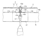
- the tip 45b of the bolt 45 protruding below the main plate 41b of the first support fitting 41 (or below the main plate 42 of the second support fitting 42) is attached to the tip of the electric drill. All the screw sockets 47 are inserted and engaged. With the electric drill, the entire screw socket 47 is rotated together with the bolt 45, and the bolt 45 is screwed downward. At the same time, the fixture 43 is moved downward together with the head 45 a of the bolt 45 against the elastic force of the coil spring 46. The pressing plate 43a of the fixture 43 is brought into contact with the frame member 4 of the solar cell module 2, and the bolt 45 is tightened (fastening step). As a result, the frame member 4 of the solar cell module 2 is sandwiched and fixed between the main plate 15 b of the horizontal rail 15 and the pressing plate 43 a of the fixing bracket 43.
- the bolt 45 is screwed in the screw hole 41e of the main plate 41b of the first support fitting 41 (or the screw hole of the main plate 42b of the second support fitting 42) in the temporary fixing step. 42e), the tip 45b of the bolt 45 is protruded downward from the main plate 41b (or main plate 42b). Accordingly, it is necessary to screw the bolt 45 downward from above, but since this work is performed through an empty space before the next solar cell module is arranged, this operation is performed above the solar cell module 2. There is no need to do it.
- the bolt 45 is tightened by rotating the tip 45b of the bolt 45 using the full screw socket 47 that engages the tip 45b of the bolt 45 protruding downward.
- the bolt 45 can be fastened from below even if there is no free space. For this reason, parts, such as a nut and a washer, do not increase, work efficiency can be improved, and work safety can be secured.
- the tightening operation is performed from below, but if the tightening operation is possible from above, the bolt 45 may be tightened from above.
- a bolt as shown in FIG. 16 may be used.
- the bolt 48 in FIG. 16 has a hexagon head 48a, a male screw shaft 48b, and a hexagon end 48c at the lower end of the shaft 48b.
- the maximum diameter of the hexagon end 48c is larger than the diameter of the shaft 48b. It is getting smaller.
- the bolt 48 is used by being passed through the perforation 43 c of the pressing plate 43 a of the fixing bracket 43 and the coil spring 46.
- the hexagonal end portion 48c of the bolt 48 is screwed into the screw hole 41e (or the main plate 41b of the first support fitting 41).
- the shaft 48b of the bolt 48 is screwed into the screw hole 41e of the main plate 41b (or the screw hole 42e of the main plate 42b) through the screw hole 42e) of the main plate 42b of the second support fitting 42, and the hexagonal end 48c of the bolt 48 is inserted. It can protrude below the main plate 41b (or main plate 42b).
- each of the first support fitting 41 and the second support fitting 42 is provided with screw holes 41e and 42e in which screw grooves are formed, and the fixing bracket 43 has no screw grooves and is simply provided with a bolt 45. While the perforation 43c to be penetrated is provided, the first and second support fittings 41 and 42 may be perforated and the fixing bracket side may be a screw hole. This eliminates the need for a separate fastening member such as a nut.
- the tip 45b of the bolt 45 is positioned above the main plate 41b of each first support fitting 41 and each second support.
- the metal plate 42 protrudes above the main plate 42. Therefore, in the subsequent fastening step, the tip 45b of the bolt 45 protruding above the main plate 41b of the first support fitting 41 (or above the main plate 42 of the second support fitting 42) is replaced with an electric drill and socket 47 or the like. And the bolt 45 may be screwed upward.
- the bolt 45 is screwed into the screw hole of the fixing bracket 43 so that the tip 45b of the bolt 45 protrudes above the pressing plate 43a.
- the screwing work is required, if this work is performed through the empty space before the next solar cell module is arranged, it is not necessary to perform this work below the solar cell module 2.
- the bolt 45 is tightened by rotating the tip 45b of the bolt 45 using the full screw socket 47 etc. that engages the tip 45b of the bolt 45 protruding upward.
- the bolt 45 can be fastened from above even if there is no free space. For this reason, when it is difficult to secure a work space for fastening bolts below the solar cell module 2, it is possible to improve work efficiency without increasing the number of parts such as nuts and washers, and to ensure work safety. can do.
- the present invention can be suitably used for a solar power generation system.
Landscapes
- Engineering & Computer Science (AREA)
- Architecture (AREA)
- Civil Engineering (AREA)
- Structural Engineering (AREA)
- Physics & Mathematics (AREA)
- Life Sciences & Earth Sciences (AREA)
- Sustainable Development (AREA)
- Sustainable Energy (AREA)
- Thermal Sciences (AREA)
- Chemical & Material Sciences (AREA)
- Combustion & Propulsion (AREA)
- Mechanical Engineering (AREA)
- General Engineering & Computer Science (AREA)
- Photovoltaic Devices (AREA)
- Roof Covering Using Slabs Or Stiff Sheets (AREA)
- Light Receiving Elements (AREA)
- Connection Of Plates (AREA)
Abstract
構造物(2)を基台(15)に載せ、構造物(2)の端部上に固定部材(43)を配置し、固定部材(43)を貫通するようにボルト(45)をねじ込んで締結する。構造物(2)の端部を、基台(15)と固定部材(43)間に挟持する。ここで、ボルト(45)を基台(14)側又は固定部材(43)側から挿入してねじ込んで、ボルト(45)の先端部(45b)を挿入側とは反対側に突出させて仮止めする。次いで、ボルト(45)の突出した先端部(45b)に係合する工具(47)を用いて、ボルト(45)の先端部(45b)を回転させ、ボルト(45)を締結する。
Description
本発明は、太陽電池モジュール等の構造物を支持するための構造物支持構造の施工方法、及びその施工方法を用いた太陽光発電システムに関する。
構造物用架台としては、複数の桟を平行に並べて固定し、各桟の間に複数の太陽電池モジュールを架け渡して、各太陽電池モジュールを支持するものがある。
また、例えば特許文献1には、太陽電池モジュールの端部を桟上に固定するべく、クランププレートを太陽電池モジュールの端部に載せ、ボルトをクランププレートの孔を介して桟側に支持されたナットにねじ込んで締め付け、太陽電池モジュールをクランププレートと桟間に挟み込んで固定する構成が開示されている。
ところが、特許文献1のようにボルトを太陽電池モジュールの端部に載せられたクランププレートの孔を介してナットへとねじ込んで締め付ける場合は、ボルトの締め付け作業を太陽電池モジュールの上方で行う必要がある。このため、太陽電池モジュールが高い位置に設置されていると、その作業が困難になり、また作業の危険性が高くなった。
また、例えば特許文献2には、ボルトを、各太陽電池モジュールの間を介して、桟の下方へと突出させ、ボルトの下端にナットをねじ込んで締め付ける構成が開示されている。この例では、ナットの締め付け作業を太陽電池モジュールの下方から行うことができ、太陽電池モジュールが高い位置に設置されていても、ナットの締め付け作業が容易であって、危険性が少ない。
しかしながら、ナットやワッシャ等を太陽電池モジュールの下方からボルトに取付ける作業が煩雑であり、また、ナットやワッシャ等の部品点数が増加する。特に、多数の太陽電池モジュールを設置する場合には、そのような取付け作業や部品点数の増加が、作業効率の大幅な低下を招くおそれがあった。
また、太陽電池モジュールの下方側からボルトの締め付け作業を行うような構成であると、太陽電池モジュールの下方に十分な作業スペースが確保できないと、作業が困難になると考えられる。
前記のように、ボルトの締め付け作業を太陽電池モジュールの上方で行う場合は、太陽電池モジュールが高い位置に設置されていると、ボルトの締め付け作業が困難になり、また作業の危険性が高くなった。
また、ボルトの下端にナットをねじ込む場合は、ナットの締め付け作業を下方から行うことができても、ナットやワッシャ等を下方からボルトに取付ける作業が煩雑であり、ナットやワッシャ等の部品が増加した。特に、多数の太陽電池モジュールを設置する場合は、そのような取付け作業や部品点数の増加が作業効率の大幅な低下を招いた。
また、下方側からボルトの締め付け作業を行うようなものでは、太陽電池モジュールの下方に十分な作業スペースが確保できないと、作業が困難となる。
そこで、本発明は、上記従来の問題点に鑑みてなされたものであり、ボルトの締め付け作業を方向性にかかわらず容易とし、部品点数の増加を招くことがなく、作業効率を向上させることが可能な構造物支持構造の施工方法、及びその施工方法を用いた太陽光発電システムを提供することを目的とする。
上記課題を解決するために、本発明の構造物支持構造の施工方法は、構造物を基台に載せ、前記構造物の端部上に固定部材を配置し、前記固定部材を貫通するようにボルトをねじ込んで締結し、前記構造物の端部を前記基台と前記固定部材間に挟持する構造物支持構造の施工方法であって、前記ボルトを前記基台側又は前記固定部材側から挿入してねじ込んで、前記ボルトの先端部を挿入側とは反対側に突出させて仮止めする工程と、前記ボルトの突出した先端部に係合する工具を用いて、前記ボルトの先端部を回転させ、前記ボルトを締結する工程とを含む構成としている。
このような施工方法によれば、仮止めする工程で、ボルトを基台側基台側又は固定部材側から挿入してねじ込んで、ボルトの先端部を挿入側とは反対側に突出させている。従って、ボルトを挿入側からその反対側にねじ込む作業が必要になるが、作業を構造物が配置される前の空きスペースを通じて行えば、作業をボルトの挿入側で行う必要がない。また、締結する工程では、ボルトの突出した先端部に係合する工具を用いて、ボルトの先端部を回転させて、ボルトを締結しているので、構造物が配置された後で、空きスペースがなくてっても、ボルトの締結作業をボルトの挿入側とは反対側で容易に行うことができる。このため、ナットやワッシャ等の部品が増加することがなく、作業効率を向上させることができ、作業の安全性を確保することができる。
また、前記構成の構造物支持構造の施工方法において、前記仮止めする工程では、前記ボルトにコイルバネを通して仮止めすることが好ましい。
このコイルバネは、ボルトが通された固定部材を押し上げる作用をなす。これにより、固定部材が基台から離間して、固定部材と基台の間に構造物の端部を容易に挿入することが可能になる。
また、前記構成の構造物支持構造の施工方法において、前記仮止めする工程では、前記ボルトを前記固定部材側から前記基台側に挿入してねじ込み、前記ボルトの先端部を前記基台の下方側に突出させ、前記ボルトを締結する工程では、前記基台の下方側に突出した前記ボルトの先端部を、前記工具により係合して回転させることが好ましい。
このような施工方法によれば、仮止めする工程で、ボルトを基台側にねじ込んで、ボルトの先端部を基台の下方に突出させている。従って、ボルトを上方から下方にねじ込む作業が必要になるが、作業を構造物が配置される前の空きスペースを通じて行えば、作業を各桟等の上方で行う必要がない。また、締結する工程では、下方に突出したボルトの先端部に係合する工具を用いて、ボルトの先端部を回転させて、ボルトを締結しているので、構造物が配置された後で、空きスペースがなくてっても、ボルトの締結作業を構造物の下方から行うことができる。このため、ナットやワッシャ等の部品が増加することがなく、作業効率を向上させることができ、作業の安全性を確保することができる。
更に、前記構成の構造物支持構造の施工方法において、前記基台となる並設された複数の桟間に、複数の前記構造物を順次架け渡して配置する工程を含み、前記仮止め工程では、前記各桟間に前記構造物が配置される度に、次の構造物が配置される前の隣の空きスペースを利用して行うことが好ましい。
これにより、ボルトを基台側にねじ込んで、ボルトの先端部を挿入側とは反対側に突出させる仮止め工程をボルトの挿入側で行う必要がなくなる。
また、前記構成の構造物支持構造の施工方法において、前記構造物は、太陽電池モジュールであってもよい。
また、上記各解決手段に係る構造物支持構造の施工方法を用いた太陽光発電システムも本発明の技術的思想の範疇である。すなわち、本発明に係る太陽光発電システムは、太陽電池モジュールの端部を前記基台と前記固定部材間に挟持する構成としている。
このような太陽光発電システムにおいても、上記構造物用架台と同様の作用効果を奏することができる。
本発明によれば、構造物が配置された後で、空きスペースがなくなっても、ボルトの締結作業をボルトの挿入側とは反対側で容易に行うことができる。このため、ナットやワッシャ等の部品が増加することがなく、作業効率を向上させることができ、作業の安全性を確保することができる。
以下、本発明の実施形態について、図面を参照しつつ詳細に説明する。
図1は、本発明の一実施形態に係る構造物支持構造の施工方法を適用した太陽光発電システムを示す斜視図である。
この太陽光発電システムは、発電所への適用を前提としたものであり、多数の太陽電池モジュールを備えている。
図1に示すように、複数の支柱11を相互に間隔を開けて地面に打ち込んで突設し、各支柱11の上端部にそれぞれの縦桟14を傾斜させて接続し、各支柱11の胴部と各縦桟14間にそれぞれ2本のアーム12、13を架け渡して接続し、これにより各支柱11の上端部に各縦桟14を支持している。そして、各縦桟14を相互に間隔を開けて平行に配置し、太陽電池モジュールの基台となる3本の横桟15を各縦桟14と直交するように配して、各横桟15を各縦桟14上に並設し、各横桟15間に複数の太陽電池モジュール2を架け渡して傾斜させ、各横桟15上に各太陽電池モジュール2の両端を固定支持している。
縦桟14には、縦桟14の長手方向に沿って離間し、縦桟14の下方に突出した一対のアーム連結部材16が設けられている。各アーム連結部材16の下方突出部分には、それぞれのアーム12、13が接続支持されている。
支柱11の胴部と2本のアーム12、13の端部との間にはそれぞれのアームブラケット22が介在し、各アーム12、13の端部が各アームブラケット22を介して連結され、各アームブラケット22の間に支柱11の胴部が支持されている。
支柱11の上端部と縦桟14間には桟ブラケット21が介在し、桟ブラケット21により支柱11の上端部と縦桟14が連結されている。
下段の横桟15と中段の横桟15の間に複数の太陽電池モジュール2が横一列に並べられて搭載され、中段の横桟15と上段の横桟15の間にも複数の太陽電池モジュール2が横一列に並べられて搭載されている。従って、3本の横桟15上に、複数の太陽電池モジュール2が2列に並べて搭載されている。また、左右に隣り合う2本の縦桟14間に、4枚又は6枚の太陽電池モジュール2が割り振られている。
尚、図1において、各支柱11が並ぶ方向をX方向(左右方向)とし、このX方向と直交する方向をY方向(前後方向)としている。
図2は、太陽電池モジュール2を示す斜視図である。図2に示すように太陽電池モジュール2は、太陽光を光電変換する太陽電池パネル3と、この太陽電池パネル3を縁取って保持する枠部材4とで構成されている。枠部材4は、アルミ材からなり、太陽電池モジュール2そのものの強度を確保したり、太陽電池パネル3を保護したりするためのものである。
図3は、支柱11、2本のアーム12、13、及び縦桟14等からなるトラス構造を示す側面図である。図3に示すように、トラス構造は、縦桟14の中央部を、桟ブラケット21を介して支柱11の上端部11dに連結し、縦桟14の先端寄りの部位にアーム12の一端部を、アーム連結部材16を介して接続し、縦桟14の後端寄りの部位にアーム13の一端部を、アーム連結部材16を介して接続し、各アーム12、13の他端部を、2個のアームブラケット22を介して支柱11の胴部11eに接続してなる。
このような支柱11、2本のアーム12、13、及び縦桟14からなるトラス構造は、太陽電池モジュール2の支持強度を高くする。
図1に示すように複数の支柱11を相互に間隔を開けて突設し、支柱11毎に、図3のトラス構造を構築して、複数の縦桟14を平行にかつ一定の間隔で並設する。そして、3本の横桟15を各縦桟14と直交するように配して、各横桟15を各縦桟14上に固定する。
次に、太陽電池モジュール2を横桟15上に固定するための第1及び第2支持金具について説明する。
図1から明らかなように中段の横桟15は、上下の太陽電池モジュール2の端部を支持し、また上段及び下段の横桟15は、上段又は下段の太陽電池モジュール2の端部を支持している。このため、中段の横桟15と上段及び下段の横桟15とで太陽電池モジュール2の支持構造が異なり、第1及び第2支持金具を使い分けている。
図4は、太陽電池モジュール2を中段の横桟15に接続して固定するための第1支持金具を示す斜視図である。図4に示すように第1支持金具41は、側板41a、側板41aの上縁で折り曲げられた主板41b、及び側板41aの下縁で折り曲げられた底板41cを有している。主板41bには、主板41bの両角部で折れ曲がって起こされた各突起片41dが形成されている。各突起片41dは、それらの上方から見ると、主板41bの両角部をえぐるように湾曲した円弧を描いている。また、主板41bの略中央にネジ孔41eが形成されている。更に、側板41aに穿孔41fが形成され、側板41aにC字形状の切り込みが形成され、この切り込みの内側部分が起こされて係合片41gとなっている。側板41aの高さは、横桟15の側板15aの高さに略等しい。
図5に示すように2個の第1支持金具41が中段の横桟15の各側板15aに重ねられ、各第1支持金具41の側板41aの係合片41gが横桟15の各側板15aのスリット(図示せず)に係合して、各第1支持金具41が仮止めされる。このとき、各第1支持金具41の主板41bが横桟15から外向きに突出し、各第1支持金具41の各突起片41dが横桟15の主板15bよりも上方に突出する。
この状態で、横桟15の各側板15a間にパイプ25を挿入して、パイプ25、横桟15の各側板15aの穿孔(図示せず)、及び各第1支持金具41の側板41aの穿孔41fを位置合わせし、ボルト26をパイプ25、横桟15の各側板15aの穿孔、各第1支持金具41の側板41aの穿孔41f、及びワッシャに通して、ボルト26の一端にナット27をねじ込んで締め込み、各第1支持金具41を中段の横桟15に固定している。
図6は、太陽電池モジュール2の受光面側に配置される固定金具を示す斜視図である。この固定金具43は、押圧板43aの前後端部に下方に折り曲げられた突起片43bを形成し、押圧板43aの中央部に穿孔43cを形成したものである。
図7に示すように固定金具43の押圧板43aの穿孔43cには、ボルト45が通され、このボルト45にコイルバネ46が差し込まれる。従って、固定金具43の押圧板43aは、ボルト45の頭部45aとコイルバネ46間に挟み込まれる。
図8及び図9は、第1支持金具41及び固定金具43を用いて、各太陽電池モジュール2を中段の横桟15に取付けた状態を上方及び下方から見て示す斜視図である。図7及び図8に示すように各太陽電池モジュール2の枠部材4を第1支持金具41の各突起片41d間に入れて横桟15の主板15b上に載置する。
そして、図10に示すように左右に隣り合う各太陽電池モジュール2の枠部材4間に固定金具43の各突起片43bを差し込んで、各太陽電池モジュール2の枠部材4を一定間隔だけ離間させ、ボルト45を固定金具43の穿孔43c及各太陽電池モジュール2の枠部材4の隙間を介して第1支持金具41の主板41bのネジ孔41eにねじ込んで締め込む。これにより、固定金具43と横桟15の主板15b間に各太陽電池モジュール2の枠部材4が挟み込まれて固定される。
図11は、太陽電池モジュール2を上段及び下段の横桟15に接続して固定するための第2支持金具を示す斜視図である。図11に示すように第2支持金具42は、相互に対向する一対の側板42a、各側板42aの対向一辺を連結する主板42b、及び各側板42aの縁で折れ曲がって外側に突出するそれぞれの鍔42cからなるハット型断面形状を有しており、横桟15の内側に嵌合するような形状及びサイズに設定されている。
この第2支持金具42の主板42bの両端から内側へとL字形の切り込みがそれぞれ形成され、これらのL字形の切り込みの内側が起こされて、それぞれの突起片42fとなっている。また、第2支持金具42の各側板42aにはそれぞれのネジ孔42dが形成され、主板42bの中心線上にネジ孔42eが形成され、各鍔42cにそれぞれの長形孔42gが形成されている。
このような第2支持金具42は、上段及び下段の横桟15の内側に嵌合される。図12に示すように第2支持金具42が横桟15の内側に嵌合されると、第2支持金具42の主板42bの各突起片42fが横桟15の主板15bの一対のスリット(図示せず)から上方に突出する。また、第2支持金具42の各側板42aが横桟15の各側板15aに重なり、第2支持金具42の主板42bが横桟15の主板15bに重なり、第2支持金具42の各鍔42cが横桟15の各鍔15cに重なる。
この状態で、2本のボルトが、横桟15の各側板15aの穿孔(図示せず)を介して第2支持金具42の各側板42aのネジ孔42dにそれぞれねじ込まれて締め込まれ、第2支持金具42が固定される。このため、第2支持金具42の部位では、主板、側板、及び鍔が2重構造となり、この部位での強度が高くなる。
図13(a)及び図13(b)は、第2支持金具42及び固定金具43を用いて、上段及び下段の横桟15に左右2枚の太陽電池モジュール2を取付けた状態を示す平面図及び断面図である。図13(a)及び図13(b)に示すように左右の各太陽電池モジュール2の枠部材4を第2支持金具42の各突起片42f間に入れて横桟15の主板15b上に載置する。そして、左右の各太陽電池モジュール2の枠部材4間に固定金具43の各突起片43bを差し込んで、各太陽電池モジュール2の枠部材4を一定間隔だけ離間させる。
引き続いて、ボルト45を固定金具43の穿孔43c、各太陽電池モジュール2の枠部材4の隙間、及び横桟15の主板15bの穿孔15eを介して第2支持金具42の主板42のネジ孔42eにねじ込んで締め込む。これにより、固定金具43と横桟15の主板15b間に各太陽電池モジュール2の枠部材4が挟み込まれて固定される。
次に、太陽電池モジュール2を構造物用架台5上に搭載して固定するための施工手順を説明する。
本実施形態では、図1における各横桟15上に、各横桟15の右端から左端の方へと太陽電池モジュール2を上下2枚ずつ架け渡して行くものとする。まず、右端1番目の上下2枚の太陽電池モジュール2を各横桟15上に架け渡す。このとき、太陽電池モジュール2の枠部材4を、第1支持金具41の各突起片41d間に入れて横桟15の主板15b上に載置する。また、太陽電池モジュール2の枠部材4を、第2支持金具42の各突起片42f間にも入れて横桟15の主板15b上に載置する。
1番目の上下2枚の太陽電池モジュール2の両側には、他の太陽電池モジュール2が配置されていない。このため、1番目の上下2枚の太陽電池モジュール2の両側に、空きスペースが在る。このため、両側の空きスペースを利用して、各第1支持金具41の部位及び各第2支持金具42の部位にそれぞれの固定金具43を配し、各ボルト45をそれぞれの固定金具43の穿孔43c及びコイルバネ46に通して各第1支持金具41の主板41bのネジ孔41e及び各第2支持金具42の主板42のネジ孔42eにねじ込み、各ボルト45の先端部45bを各第1支持金具41の主板41bの下方及び各第2支持金具42の主板42の下方に突出させる(仮止め工程)。
この仮止め工程では、各ボルト45を適宜ねじ込んで、各ボルト45の頭部45aを太陽電池モジュール2の枠部材4から一定距離以上、離間させておく。この状態では、各ボルト45のコイルバネ46によりそれぞれの固定金具43の押圧板43aが押し上げられて太陽電池モジュール2の枠部材4から離間し、各固定金具43の押圧板43aと各第1支持金具41の主板41b及び各第2支持金具42の主板42bとの間に適宜の隙間が設定される。
この結果、1番目の上下2枚の太陽電池モジュール2の両側に沿って、固定金具43が4個ずつ配置され仮止めされる。
次に、2番目の上下2枚の太陽電池モジュール2を各横桟15上に架け渡して、太陽電池モジュール2の枠部材4を、第1支持金具41の各突起片41d間に入れて載置する。また、太陽電池モジュール2の枠部材4を、第2支持金具42の各突起片42f間にも入れて載置する。
このとき、2番目の上下2枚の太陽電池モジュール2の枠部材4右側を、1番目の上下2枚の太陽電池モジュール2の枠部材4左側に接近させ、1番目の各太陽電池モジュール2の枠部材4左側に沿って配された4個の固定金具43と、各第1支持金具41の主板41b及び各第2支持金具42の主板42bとの間に、差し入れる。各固定金具43を仮止めして、各固定金具43の押圧板43aと各第1支持金具41の主板41b及び各第2支持金具42の主板42bとの間に適宜の隙間を設定しているので、2番目の各太陽電池モジュール2の枠部材4右側をその隙間に容易に差し入れることができる。
また、2番目の各太陽電池モジュール2の枠部材4右側と、1番目の各太陽電池モジュール2の枠部材4左側との間に、各固定金具43の突起片43bを挟み込んで、2番目の各太陽電池モジュール2と1番目の各太陽電池モジュール2との隙間を一定にする。
そして、次に配置される3番目の上下2枚の太陽電池モジュール2の空きスペースを通じて、2番目の上下2枚の太陽電池モジュール2の枠部材4左側に沿って在る各第1支持金具41の部位及び各第2支持金具42の部位にそれぞれの固定金具43を配し、各ボルト45をそれぞれの固定金具43の穿孔43c及びコイルバネ46に通して各第1支持金具41の主板41bのネジ孔41e及び各第2支持金具42の主板42のネジ孔42eにねじ込み、各ボルト45の先端部45bを各第1支持金具41の主板41bの下方及び各第2支持金具42の主板42の下方に突出させるという仮止め工程を行う。
以降、図14(a)及び図14(b)に示すように、(n-1)番目の太陽電池モジュール2の枠部材4右側を、固定金具43と第1支持金具41の主板41b(又は各第2支持金具42の主板42b)との間に差し入れる。(n-1)番目の太陽電池モジュール2の枠部材4右側と、n番目の太陽電池モジュール2の枠部材4左側との間に、固定金具43の突起片43bを挟み込む。(n-1)番目の太陽電池モジュール2と、n番目の太陽電池モジュール2との隙間を一定にする。
図14(c)及び図14(d)に示すように、次に配置される(n+1)番目の太陽電池モジュール2の空きスペースを利用して、n番目の太陽電池モジュール2の枠部材4左側に沿って在る第1支持金具41の部位(又は第2支持金具42の部位)に、固定金具43を配置する。そして、ボルト45を、固定金具43の穿孔43c及びコイルバネ46に通して、第1支持金具41の主板41bのネジ孔41e(又は第2支持金具42の主板42bのネジ孔42e)にねじ込み、ボルト45の先端部45bを第1支持金具41の主板41bの下方(又は第2支持金具42の主板42の下方)に突出させる、という仮止め工程を行う。
これにより、図1に示すように下段の横桟15と中段の横桟15の間に、複数の太陽電池モジュール2が横一列に並べられる。中段の横桟15と上段の横桟15の間にも、複数の太陽電池モジュール2が横一列に並べられる。
こうして3本の横桟15上に複数の太陽電池モジュール2が2列で並べられた状態では、各ボルト45をその上方から締め付ける作業が困難になる。
そこで、図15に示すように、第1支持金具41の主板41bの下方(又は第2支持金具42の主板42の下方)に突出したボルト45の先端部45bを、電動ドリルの先端に取付けられた全ねじソケット47に差し込んで係合させる。その電動ドリルにより、全ねじソケット47を、ボルト45と共に回転させ、ボルト45を下方へとねじ込ませる。同時に、固定金具43を、ボルト45の頭部45aと共に、コイルバネ46の弾性力に抗して下方に移動させる。固定金具43の押圧板43aを、太陽電池モジュール2の枠部材4に当接させ、ボルト45を締め付ける(締結する工程)。これにより、横桟15の主板15bと固定金具43の押圧板43aとの間に、太陽電池モジュール2の枠部材4が挟み込まれて固定される。
このような方法で、各第1支持金具41の主板41b及び各第2支持金具42の主板42bの下方に突出した全てのボルト45を締め付けると、全ての太陽電池モジュール2の枠部材が、各横桟15の主板15bと各固定金具43の押圧板43a間に挟み込まれて固定される。
このような実施形態に係る構造物支持構造の施工方法では、仮止めする工程で、ボルト45を第1支持金具41の主板41bのネジ孔41e(又は第2支持金具42の主板42bのネジ孔42e)にねじ込んで、ボルト45の先端部45bを主板41b(又は主板42b)下方に突出させている。従って、ボルト45を上方から下方にねじ込む作業が必要になるが、この作業を次の順番の太陽電池モジュールが配置される前の空きスペースを通じて行っているので、この作業を太陽電池モジュール2の上方で行う必要がない。また、ボルト45を締結する工程では、下方に突出したボルト45の先端部45bに係合する全ねじソケット47を用いて、ボルト45の先端部45bを回転させて、ボルト45を締め付けているので、太陽電池モジュール2が配置された後で、空きスペースがなくなっても、ボルト45の締結作業を下方から行うことができる。このため、ナットやワッシャ等の部品が増加することがなく、作業効率を向上させることができ、作業の安全性を確保することができる。
尚、本実施形態では、下方向から締め付け作業を行っているが、上方向からの締め付け作業か可能である場合には、上方向からボルト45の締め付け作業を行ってもよい。
以上、本発明における好適な実施形態について説明したが、本発明は係る例に限定されない。
例えば、図16に示すようなボルトを用いてもよい。図16のボルト48は、六角頭部48a、雄ネジの軸部48b、及び軸部48b下端の六角端部48cを有しており、六角端部48cの最大径が軸部48bの直径よりも小さくなっている。このボルト48は、ボルト45と同様に、固定金具43の押圧板43aの穿孔43c及びコイルバネ46に通されて用いられる。
ボルト48の六角端部48cの最大径は、その軸部48bの直径よりも小さく設定されていることから、ボルト48の六角端部48cを第1支持金具41の主板41bのネジ孔41e(又は第2支持金具42の主板42bのネジ孔42e)に通して、ボルト48の軸部48bを主板41bのネジ孔41e(又は主板42bのネジ孔42e)にねじ込み、ボルト48の六角端部48cを主板41b(又は主板42b)の下方に突出させることができる。そして、下方に突出したボルト48の六角端部48cを、電動ドリルの先端に取付けられたソケットレンチに差し込んで係合させ、電動ドリルによりソケットレンチをボルト48と共に回転させて、ボルト48を締め付けることができる。
また、上記実施形態においては、仮止めの際に、ボルト45を固定金具43側から挿入して横桟15側にねじ込み、横桟15の下方側にボルト45の先端部45を突出させるものについて説明したが、ボルト45を反対側から挿入するようにしても良い。この場合、上記実施形態において、第1支持金具41及び第2支持金具42のそれぞれに、ネジ溝が形成されたネジ孔41e、42eを設け、固定金具43にネジ溝がなくて単にボルト45を貫通させる穿孔43cを設けたのに対して、第1、2支持金具41、42側を穿孔とし、固定金具側をネジ孔とすればよい。そうすれば別途ナット等の締結用部材を用いる必要がなくなる。
このように、仮止めの際に、ボルト45を上記実施形態とは反対側から挿入する場合には、ボルト45の先端部45bを各第1支持金具41の主板41bの上方及び各第2支持金具42の主板42の上方に突出させることになる。したがって、この後の締結する工程では、第1支持金具41の主板41bの上方(又は第2支持金具42の主板42の上方)に突出したボルト45の先端部45bを、電動ドリル及びソケット47等を用いて、ボルト45を上方へとねじ込ませればよい。
このような場合においては、仮止めする工程で、ボルト45を固定金具43のネジ孔にねじ込んで、ボルト45の先端部45bを押圧板43aの上方に突出させるため、ボルト45を下方から上方にねじ込む作業が必要になるが、この作業を次の順番の太陽電池モジュールが配置される前の空きスペースを通じて行えば、この作業を太陽電池モジュール2の下方で行う必要がない。また、ボルト45を締結する工程では、上方に突出したボルト45の先端部45bに係合する全ねじソケット47等を用いて、ボルト45の先端部45bを回転させて、ボルト45を締め付けるので、太陽電池モジュール2が配置された後で、空きスペースがなくなっても、ボルト45の締結作業を上方から行うことができる。このため、太陽電池モジュール2下方にボルト締結用の作業スペースが確保し難い場合において、ナットやワッシャ等の部品が増加することがなく、作業効率を向上させることができ、作業の安全性を確保することができる。
なお、本発明は、その精神または主要な特徴から逸脱することなく、他の様々な形で実施することができる。そのため、上述の実施形態はあらゆる点で単なる例示にすぎず、限定的に解釈してはならない。本発明の範囲は特許請求の範囲によって示すものであって、明細書本文には、なんら拘束されない。さらに、特許請求の範囲の均等範囲に属する変形や変更は、全て本発明の範囲内のものである。
なお、この出願は、日本で2010年8月4日に出願された特願2010-175677号に基づく優先権を請求する。その内容は、これに言及することにより、本出願に組み込まれるものである。また、本明細書に引用された文献は、これに言及することにより、そのすべてが具体的に組み込まれるものである。
本発明は、太陽光発電システムに好適に利用可能である。
2 太陽電池モジュール(構造物)
11 支柱
12、13 アーム
14 縦桟
15 横桟(基台)
16 アーム連結部材
21 桟ブラケット
22 アームブラケット
25 パイプ
26、45 ボルト
27 ナット
31 取付け金具
41 第1支持金具
42 第2支持金具
43 固定金具(固定部材)
47 全ねじソケット(工具)
11 支柱
12、13 アーム
14 縦桟
15 横桟(基台)
16 アーム連結部材
21 桟ブラケット
22 アームブラケット
25 パイプ
26、45 ボルト
27 ナット
31 取付け金具
41 第1支持金具
42 第2支持金具
43 固定金具(固定部材)
47 全ねじソケット(工具)
Claims (6)
- 構造物を基台に載せ、前記構造物の端部上に固定部材を配置し、前記固定部材を貫通するようにボルトをねじ込んで締結し、前記構造物の端部を前記基台と前記固定部材間に挟持する構造物支持構造の施工方法であって、
前記ボルトを前記基台側又は前記固定部材側から挿入してねじ込んで、前記ボルトの先端部を挿入側とは反対側に突出させて仮止めする工程と、
前記ボルトの突出した先端部に係合する工具を用いて、前記ボルトの先端部を回転させ、前記ボルトを締結する工程とを含むことを特徴とする構造物支持構造の施工方法。 - 請求項1に記載の構造物支持構造の施工方法であって、
前記仮止めする工程では、前記ボルトにコイルバネを通して仮止めすることを特徴とする構造物支持構造の施工方法。 - 請求項1に記載の構造物支持構造の施工方法であって、
前記仮止めする工程では、前記ボルトを前記固定部材側から前記基台側に挿入してねじ込み、前記ボルトの先端部を前記基台の下方側に突出させ、
前記ボルトを締結する工程では、前記基台の下方側に突出した前記ボルトの先端部を、前記工具を係合して回転させることを特徴とする構造物支持構造の施工方法。 - 請求項1に記載の構造物支持構造の施工方法であって、
前記基台となる並設された複数の桟間に、複数の前記構造物を順次架け渡して配置する工程を含み、
前記仮止め工程は、前記各桟間に前記構造物が配置される度に、次の構造物が配置される前の隣の空きスペースを利用して行うことを特徴とする構造物支持構造の施工方法。 - 請求項1に記載の構造物支持構造の施工方法であって、
前記構造物は、太陽電池モジュールであることを特徴とする構造物支持構造の施工方法。 - 請求項1~5のいずれか1つに記載の構造物支持構造の施工方法を用いた太陽光発電システムであって、
太陽電池モジュールの端部を前記基台と前記固定部材間に挟持したことを特徴とする太陽光発電システム。
Applications Claiming Priority (2)
| Application Number | Priority Date | Filing Date | Title |
|---|---|---|---|
| JP2010175677A JP5637762B2 (ja) | 2010-08-04 | 2010-08-04 | 構造物支持構造の施工方法、構造物支持構造、及びその施工方法又は構造物支持構造を用いた太陽光発電システム |
| JP2010-175677 | 2010-08-04 |
Publications (1)
| Publication Number | Publication Date |
|---|---|
| WO2012018012A1 true WO2012018012A1 (ja) | 2012-02-09 |
Family
ID=45559509
Family Applications (1)
| Application Number | Title | Priority Date | Filing Date |
|---|---|---|---|
| PCT/JP2011/067672 Ceased WO2012018012A1 (ja) | 2010-08-04 | 2011-08-02 | 構造物支持構造の施工方法、及びその施工方法を用いた太陽光発電システム |
Country Status (2)
| Country | Link |
|---|---|
| JP (1) | JP5637762B2 (ja) |
| WO (1) | WO2012018012A1 (ja) |
Cited By (2)
| Publication number | Priority date | Publication date | Assignee | Title |
|---|---|---|---|---|
| WO2014061437A1 (ja) * | 2012-10-19 | 2014-04-24 | シャープ株式会社 | 太陽電池モジュール支持構造、及びその設置方法 |
| US20240072718A1 (en) * | 2022-02-17 | 2024-02-29 | Gamechange Solar Corp. | Fixed tilt solar panel mounting assembly with ascending and descending panel orientation |
Families Citing this family (3)
| Publication number | Priority date | Publication date | Assignee | Title |
|---|---|---|---|---|
| JP2013177769A (ja) * | 2012-02-28 | 2013-09-09 | Okuchi Kensan Kk | ソーラーパネル等の面状物品支持構造 |
| KR200467819Y1 (ko) | 2013-02-01 | 2013-07-08 | 쏠라이앤에스(주) | 태양전지모듈 지지용 구조물 시스템 |
| US9531319B2 (en) | 2013-12-23 | 2016-12-27 | Sunpower Corporation | Clamps for solar systems |
Citations (3)
| Publication number | Priority date | Publication date | Assignee | Title |
|---|---|---|---|---|
| JPS58178541U (ja) * | 1982-05-26 | 1983-11-29 | 株式会社日立製作所 | 圧縮機の固定用ボルト |
| JPH09273525A (ja) * | 1996-04-05 | 1997-10-21 | Nec Corp | 両頭ボルト |
| JP2001049816A (ja) * | 1999-08-11 | 2001-02-20 | Daiwa House Ind Co Ltd | 太陽電池付き屋根の構造及び施工方法 |
-
2010
- 2010-08-04 JP JP2010175677A patent/JP5637762B2/ja not_active Expired - Fee Related
-
2011
- 2011-08-02 WO PCT/JP2011/067672 patent/WO2012018012A1/ja not_active Ceased
Patent Citations (3)
| Publication number | Priority date | Publication date | Assignee | Title |
|---|---|---|---|---|
| JPS58178541U (ja) * | 1982-05-26 | 1983-11-29 | 株式会社日立製作所 | 圧縮機の固定用ボルト |
| JPH09273525A (ja) * | 1996-04-05 | 1997-10-21 | Nec Corp | 両頭ボルト |
| JP2001049816A (ja) * | 1999-08-11 | 2001-02-20 | Daiwa House Ind Co Ltd | 太陽電池付き屋根の構造及び施工方法 |
Cited By (3)
| Publication number | Priority date | Publication date | Assignee | Title |
|---|---|---|---|---|
| WO2014061437A1 (ja) * | 2012-10-19 | 2014-04-24 | シャープ株式会社 | 太陽電池モジュール支持構造、及びその設置方法 |
| JP2014084583A (ja) * | 2012-10-19 | 2014-05-12 | Sharp Corp | 太陽電池モジュール支持構造、及びその設置方法 |
| US20240072718A1 (en) * | 2022-02-17 | 2024-02-29 | Gamechange Solar Corp. | Fixed tilt solar panel mounting assembly with ascending and descending panel orientation |
Also Published As
| Publication number | Publication date |
|---|---|
| JP2012036595A (ja) | 2012-02-23 |
| JP5637762B2 (ja) | 2014-12-10 |
Similar Documents
| Publication | Publication Date | Title |
|---|---|---|
| JP5571362B2 (ja) | 屋根 | |
| JP5274637B2 (ja) | 構造物設置用架台、構造物設置用架台の施工方法、及び太陽電池システム | |
| JP5912100B2 (ja) | 太陽光発電パネル架台 | |
| JP2008214875A (ja) | 太陽電池モジュールの取付け構造 | |
| EP2559825A1 (en) | Solar cell module support structure, method of constructing said support structure, and solar photovoltaic power generation system using said support structure | |
| KR101231150B1 (ko) | 태양광 모듈 고정용 클램프 | |
| JP2012036594A (ja) | 架台用部材、構造物用架台、その架台の施工方法、及びその架台を用いた太陽光発電システム | |
| JPWO2011077538A1 (ja) | 補助部材 | |
| JP5637762B2 (ja) | 構造物支持構造の施工方法、構造物支持構造、及びその施工方法又は構造物支持構造を用いた太陽光発電システム | |
| WO2011099564A1 (ja) | 構造物支持構造、構造物用架台、その架台を用いた構造物の施工方法、及び太陽光発電システム | |
| JP2009041286A (ja) | 構造物設置架台、その組立方法、太陽電池モジュール、及び構造物設置架台を用いた施工構造 | |
| JP2014047570A (ja) | ソーラーパネル用固定具 | |
| JP5731220B2 (ja) | 太陽光発電ユニットの取付装置 | |
| KR101156747B1 (ko) | 태양전지모듈 고정 클램프 | |
| JP2011153465A (ja) | 構造物固定構造、その構造物固定構造に用いられる固定具、太陽電池モジュール用架台、太陽電池モジュールの施工方法、及び太陽電池発電システム | |
| JP6623946B2 (ja) | 太陽光発電パネル用固定具 | |
| JP2004084369A (ja) | 太陽光利用装置の固定構造 | |
| KR101427227B1 (ko) | 태양전지 패널 장착 프레임 | |
| JP2007205058A (ja) | 太陽電池モジュール、および太陽電池モジュールの折版屋根への取り付け構造 | |
| JP2014212177A (ja) | 太陽電池アレイの据付装置 | |
| JP6574597B2 (ja) | 太陽電池モジュール設置架台及び太陽電池モジュールの取付方法 | |
| JP6053499B2 (ja) | ソーラーパネル支持構造体 | |
| KR101158552B1 (ko) | 태양전지모듈 고정 클램프 | |
| JP2017066806A (ja) | 太陽電池モジュールの設置構造、設置方法、及びその設置構造を用いた太陽光発電システム | |
| JP2016067153A (ja) | 太陽電池モジュールの設置構造、太陽電池モジュールの設置方法及び太陽光発電システム |
Legal Events
| Date | Code | Title | Description |
|---|---|---|---|
| 121 | Ep: the epo has been informed by wipo that ep was designated in this application |
Ref document number: 11814637 Country of ref document: EP Kind code of ref document: A1 |
|
| NENP | Non-entry into the national phase |
Ref country code: DE |
|
| 122 | Ep: pct application non-entry in european phase |
Ref document number: 11814637 Country of ref document: EP Kind code of ref document: A1 |