WO2012018011A1 - 架台用部材、構造物用架台、その架台の施工方法、及びその架台を用いた太陽光発電システム - Google Patents
架台用部材、構造物用架台、その架台の施工方法、及びその架台を用いた太陽光発電システム Download PDFInfo
- Publication number
- WO2012018011A1 WO2012018011A1 PCT/JP2011/067671 JP2011067671W WO2012018011A1 WO 2012018011 A1 WO2012018011 A1 WO 2012018011A1 JP 2011067671 W JP2011067671 W JP 2011067671W WO 2012018011 A1 WO2012018011 A1 WO 2012018011A1
- Authority
- WO
- WIPO (PCT)
- Prior art keywords
- arm
- arms
- crosspiece
- vertical
- bracket
- Prior art date
- Legal status (The legal status is an assumption and is not a legal conclusion. Google has not performed a legal analysis and makes no representation as to the accuracy of the status listed.)
- Ceased
Links
Images











Classifications
-
- F—MECHANICAL ENGINEERING; LIGHTING; HEATING; WEAPONS; BLASTING
- F24—HEATING; RANGES; VENTILATING
- F24S—SOLAR HEAT COLLECTORS; SOLAR HEAT SYSTEMS
- F24S25/00—Arrangement of stationary mountings or supports for solar heat collector modules
- F24S25/10—Arrangement of stationary mountings or supports for solar heat collector modules extending in directions away from a supporting surface
- F24S25/12—Arrangement of stationary mountings or supports for solar heat collector modules extending in directions away from a supporting surface using posts in combination with upper profiles
-
- B—PERFORMING OPERATIONS; TRANSPORTING
- B23—MACHINE TOOLS; METAL-WORKING NOT OTHERWISE PROVIDED FOR
- B23P—METAL-WORKING NOT OTHERWISE PROVIDED FOR; COMBINED OPERATIONS; UNIVERSAL MACHINE TOOLS
- B23P11/00—Connecting or disconnecting metal parts or objects by metal-working techniques not otherwise provided for
-
- F—MECHANICAL ENGINEERING; LIGHTING; HEATING; WEAPONS; BLASTING
- F24—HEATING; RANGES; VENTILATING
- F24S—SOLAR HEAT COLLECTORS; SOLAR HEAT SYSTEMS
- F24S25/00—Arrangement of stationary mountings or supports for solar heat collector modules
- F24S25/60—Fixation means, e.g. fasteners, specially adapted for supporting solar heat collector modules
- F24S25/63—Fixation means, e.g. fasteners, specially adapted for supporting solar heat collector modules for fixing modules or their peripheral frames to supporting elements
- F24S25/634—Clamps; Clips
- F24S25/636—Clamps; Clips clamping by screw-threaded elements
-
- F—MECHANICAL ENGINEERING; LIGHTING; HEATING; WEAPONS; BLASTING
- F24—HEATING; RANGES; VENTILATING
- F24S—SOLAR HEAT COLLECTORS; SOLAR HEAT SYSTEMS
- F24S25/00—Arrangement of stationary mountings or supports for solar heat collector modules
- F24S25/60—Fixation means, e.g. fasteners, specially adapted for supporting solar heat collector modules
- F24S25/65—Fixation means, e.g. fasteners, specially adapted for supporting solar heat collector modules for coupling adjacent supporting elements, e.g. for connecting profiles together
-
- F—MECHANICAL ENGINEERING; LIGHTING; HEATING; WEAPONS; BLASTING
- F24—HEATING; RANGES; VENTILATING
- F24S—SOLAR HEAT COLLECTORS; SOLAR HEAT SYSTEMS
- F24S25/00—Arrangement of stationary mountings or supports for solar heat collector modules
- F24S25/70—Arrangement of stationary mountings or supports for solar heat collector modules with means for adjusting the final position or orientation of supporting elements in relation to each other or to a mounting surface; with means for compensating mounting tolerances
-
- H—ELECTRICITY
- H02—GENERATION; CONVERSION OR DISTRIBUTION OF ELECTRIC POWER
- H02S—GENERATION OF ELECTRIC POWER BY CONVERSION OF INFRARED RADIATION, VISIBLE LIGHT OR ULTRAVIOLET LIGHT, e.g. USING PHOTOVOLTAIC [PV] MODULES
- H02S20/00—Supporting structures for PV modules
- H02S20/10—Supporting structures directly fixed to the ground
-
- H—ELECTRICITY
- H02—GENERATION; CONVERSION OR DISTRIBUTION OF ELECTRIC POWER
- H02S—GENERATION OF ELECTRIC POWER BY CONVERSION OF INFRARED RADIATION, VISIBLE LIGHT OR ULTRAVIOLET LIGHT, e.g. USING PHOTOVOLTAIC [PV] MODULES
- H02S20/00—Supporting structures for PV modules
- H02S20/30—Supporting structures being movable or adjustable, e.g. for angle adjustment
-
- F—MECHANICAL ENGINEERING; LIGHTING; HEATING; WEAPONS; BLASTING
- F24—HEATING; RANGES; VENTILATING
- F24S—SOLAR HEAT COLLECTORS; SOLAR HEAT SYSTEMS
- F24S25/00—Arrangement of stationary mountings or supports for solar heat collector modules
- F24S25/60—Fixation means, e.g. fasteners, specially adapted for supporting solar heat collector modules
- F24S2025/6002—Fixation means, e.g. fasteners, specially adapted for supporting solar heat collector modules by using hooks
-
- F—MECHANICAL ENGINEERING; LIGHTING; HEATING; WEAPONS; BLASTING
- F24—HEATING; RANGES; VENTILATING
- F24S—SOLAR HEAT COLLECTORS; SOLAR HEAT SYSTEMS
- F24S25/00—Arrangement of stationary mountings or supports for solar heat collector modules
- F24S25/30—Arrangement of stationary mountings or supports for solar heat collector modules using elongate rigid mounting elements extending substantially along the supporting surface, e.g. for covering buildings with solar heat collectors
- F24S25/33—Arrangement of stationary mountings or supports for solar heat collector modules using elongate rigid mounting elements extending substantially along the supporting surface, e.g. for covering buildings with solar heat collectors forming substantially planar assemblies, e.g. of coplanar or stacked profiles
- F24S25/35—Arrangement of stationary mountings or supports for solar heat collector modules using elongate rigid mounting elements extending substantially along the supporting surface, e.g. for covering buildings with solar heat collectors forming substantially planar assemblies, e.g. of coplanar or stacked profiles by means of profiles with a cross-section defining separate supporting portions for adjacent modules
-
- Y—GENERAL TAGGING OF NEW TECHNOLOGICAL DEVELOPMENTS; GENERAL TAGGING OF CROSS-SECTIONAL TECHNOLOGIES SPANNING OVER SEVERAL SECTIONS OF THE IPC; TECHNICAL SUBJECTS COVERED BY FORMER USPC CROSS-REFERENCE ART COLLECTIONS [XRACs] AND DIGESTS
- Y02—TECHNOLOGIES OR APPLICATIONS FOR MITIGATION OR ADAPTATION AGAINST CLIMATE CHANGE
- Y02E—REDUCTION OF GREENHOUSE GAS [GHG] EMISSIONS, RELATED TO ENERGY GENERATION, TRANSMISSION OR DISTRIBUTION
- Y02E10/00—Energy generation through renewable energy sources
- Y02E10/40—Solar thermal energy, e.g. solar towers
- Y02E10/47—Mountings or tracking
-
- Y—GENERAL TAGGING OF NEW TECHNOLOGICAL DEVELOPMENTS; GENERAL TAGGING OF CROSS-SECTIONAL TECHNOLOGIES SPANNING OVER SEVERAL SECTIONS OF THE IPC; TECHNICAL SUBJECTS COVERED BY FORMER USPC CROSS-REFERENCE ART COLLECTIONS [XRACs] AND DIGESTS
- Y02—TECHNOLOGIES OR APPLICATIONS FOR MITIGATION OR ADAPTATION AGAINST CLIMATE CHANGE
- Y02E—REDUCTION OF GREENHOUSE GAS [GHG] EMISSIONS, RELATED TO ENERGY GENERATION, TRANSMISSION OR DISTRIBUTION
- Y02E10/00—Energy generation through renewable energy sources
- Y02E10/50—Photovoltaic [PV] energy
-
- Y—GENERAL TAGGING OF NEW TECHNOLOGICAL DEVELOPMENTS; GENERAL TAGGING OF CROSS-SECTIONAL TECHNOLOGIES SPANNING OVER SEVERAL SECTIONS OF THE IPC; TECHNICAL SUBJECTS COVERED BY FORMER USPC CROSS-REFERENCE ART COLLECTIONS [XRACs] AND DIGESTS
- Y10—TECHNICAL SUBJECTS COVERED BY FORMER USPC
- Y10T—TECHNICAL SUBJECTS COVERED BY FORMER US CLASSIFICATION
- Y10T29/00—Metal working
- Y10T29/49—Method of mechanical manufacture
- Y10T29/49826—Assembling or joining
Definitions
- the present invention relates to a frame member for supporting a structure such as a solar cell module, a structure frame, a method for constructing the frame, and a photovoltaic power generation system using the frame.
- This type of gantry consists of many parts, such as multiple bars, multiple columns that support each beam, and multiple arms that connect each beam to the columns. Was. For this reason, after the assembly of the crosspiece at the factory, it was transported to the work site, and the crosspiece was connected to the support post via the arm at the worksite to complete the frame.
- Patent Document 1 a connection terminal and a wiring are provided in advance on a roofing material in which a rubber substrate, a reinforcing layer, and an adhesive layer are laminated, and the roofing material is fixed on the roof.
- a configuration in which a plurality of solar cell modules are connected in parallel is disclosed.
- each crosspiece becomes a ladder-like flat structure.
- the flat structures can be easily stacked and transported.
- the crosspiece and the arm are assembled, a plurality of arms are attached to the flat structure, and the structure is not flat. If it does so, it will be bulky at the time of conveyance, it may not be stacked, and conveyance may become difficult.
- Patent Document 1 the roofing material disclosed in Patent Document 1 is premised on being spread on a flat surface such as a roof, and cannot be installed on a gantry composed of a plurality of crosspieces or columns. The simplification is not realized.
- the present invention has been made in view of the above-described conventional problems, and can be transported as a flat structure, and the gantry member and structure capable of greatly simplifying the assembly work on site. It is an object of the present invention to provide an object stand, a method for constructing the stand, and a solar power generation system using the stand.
- a gantry member is a gantry member that supports a structure, and includes a beam, two arms connected to a column that supports the beam, and the beam. And the two arms so that the longitudinal directions of the two arms are aligned and the two arms are aligned in a straight line, and the two arms are overlapped with each other.
- the thickness of the gantry member becomes substantially equal to the sum of the thickness of the arm and the thickness of the beam, and the gantry member becomes bulky. Therefore, a plurality of mount members can be stacked. For this reason, each arm can be assembled together with each crosspiece at the factory, and a plurality of mount members can be stacked and transported. Also, if the opposite sides of the two arms are separated from the crosspiece, the crosspiece can be attached to the post by connecting the opposite end of each arm to the post, and the crosspiece can be attached to the post via the arm. The work to connect is easy.
- the column that supports the crosspiece is provided with each arm bracket that connects the opposite end portion of each arm, and each arm bracket is provided on the opposite end portion of each arm. It is preferable to be provided rotatably.
- each arm can be connected to the support via each arm bracket.
- the arm brackets are rotated so as to face the crosspieces so that the crosspieces can be accommodated inside the arm brackets.
- the gantry member having the above structure includes a crosspiece bracket that connects the crosspiece on a post that supports the crosspiece, and the crosspiece bracket can be rotated to a portion between the arm connection members of the crosspiece. It is preferable to provide.
- the crosspiece can be connected to the upper end of the post via the crosspiece bracket.
- the beam bracket can be rotated and stored inside the beam.
- the structure mount according to the present invention includes a support column that supports the crosspiece, and the opposite end portion of each arm is used as the support post in a state where the opposite end portion of each arm is separated from the crosspiece. It is configured to connect.
- the truss structure can be constructed by connecting the opposite end of each arm to the support column with the opposite end of each arm being separated from the crosspiece.
- the structural mount having the above-described structure includes a plurality of sets of the crosspieces and the two arms, and the vertical crosspieces are arranged side by side, and the vertical crosspieces are arranged side by side. It is preferable that a plurality of horizontal bars are arranged side by side so as to be orthogonal to the vertical bars.
- the structural body may be a solar cell module.
- the gantry member according to the present invention includes a plurality of vertical bars arranged side by side, two arms provided for each of the vertical bars and supporting the vertical bars, and the vertical bars.
- a pair of arm connecting members to be connected and a plurality of horizontal bars arranged in parallel on the vertical bars so as to be orthogonal to the vertical bars may be provided.
- each vertical beam is arranged in parallel, each horizontal beam is arranged on each vertical beam so as to be orthogonal to each vertical beam, and the vertical beam and the two arms are overlapped.
- the frame member is flat, and a plurality of frame members can be stacked.
- each arm can be assembled together with each vertical beam and each horizontal beam at a factory, and a plurality of mount members can be stacked and transported. Furthermore, since the opposite end portions of the two arms can be separated from the vertical beam, in this state, if the opposite end portion of each arm is connected to the column, the vertical beam is attached to the column. This makes it easy to connect the vertical beam to the column via the arm.
- the construction method of the structure mount provided with the mount member according to each of the above solutions is also within the scope of the technical idea of the present invention. That is, in the construction method of the structure pedestal according to the present invention, the step of projecting the column, the bar and the arms are lifted and moved to above the projecting position of the column and then lowered, And a step of connecting the opposing side end of each arm to the column in a state where the opposing side end of each arm is separated from the crosspiece.
- the construction method of the structural stand according to the present invention is a construction method of the structural stand provided with the above-described structural member of the present invention, and projects each column corresponding to each vertical rail. And a plurality of vertical bars and the arms connected by the horizontal bars are lifted and moved above the projecting position of the column, and then lowered so that the opposite end portions of the arms are And a step of connecting the opposing side end of each arm to the column in a state of being separated from the crosspiece.
- the photovoltaic power generation system according to the present invention is configured to support a plurality of solar cell modules that are bridged between the horizontal rails.
- the thickness of the gantry member is substantially equal to the sum of the thickness of the arm and the crosspiece. Therefore, the gantry member is not bulky, and a plurality of gantry members can be stacked. Moreover, each arm can be assembled together with each crosspiece in a factory, and a plurality of mount members can be stacked and transported. Furthermore, if the opposite sides of the two arms are separated from the crosspiece, the crosspiece can be attached to the post by connecting the opposite end of each arm to the post, and the crosspiece can be attached to the post via the arm. It is possible to easily perform the operation of connecting to.
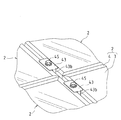
- FIG. 1 is a perspective view showing a structural stand according to an embodiment of the present invention and a solar power generation system that supports a plurality of solar cell modules using the structural stand.
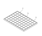
- FIG. 2 is a perspective view showing an example of a solar cell module.
- FIG. 3 is a perspective view showing a column used in the structure mount of FIG. 4 (a) and 4 (b) are perspective views showing two arms having different lengths used in the structure mount of FIG.
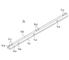
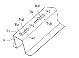
- FIG. 5 is a perspective view showing a vertical beam used in the structure mount of FIG.
- FIG. 6 is a perspective view showing a crosspiece used in the structure mount of FIG.
- FIG. 7 is a perspective view showing an arm connecting member used in the structure mount of FIG. FIG.
- FIG. 8 is a perspective view showing a crosspiece bracket used in the structure mount of FIG.
- FIG. 9 is a perspective view showing an arm bracket used in the structure mount of FIG.
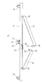
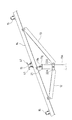
- FIG. 10 is a side view showing a truss structure including a column, two arms, a vertical rail, and the like.
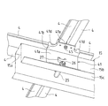
- FIG. 11 is an enlarged side view showing a connecting portion between the vertical beam and the arm bracket in the truss structure of FIG.
- FIG. 12 is an enlarged cross-sectional view showing a connecting portion between the vertical beam and the arm bracket.
- FIG. 13 is a perspective view showing a mounting bracket used for connecting and fixing the horizontal beam to the vertical beam.
- FIG. 14 is a perspective view showing a state in which the attachment fitting of FIG. 13 is attached to the vertical rail.
- FIG. 15 is a cross-sectional view showing a state in which the horizontal rail is connected to the vertical rail.
- FIG. 16 is a perspective view showing a first support fitting for connecting and fixing the solar cell module to the middle horizontal rail.
- FIG. 17 is an explanatory view showing a state in which two first support fittings are attached to the cross rail.
- FIG. 18 is a perspective view showing a second support fitting for connecting and fixing the solar cell module to the upper and lower horizontal rails.
- FIG. 19 is a cross-sectional view showing a state in which the second support fitting is attached to the cross rail.
- FIG. 20 is a side view showing a state in which the crosspiece bracket is housed inside the vertical crosspiece.
- FIG. 21 is a side view showing a state in which each arm is closed in parallel with the vertical rail and each arm bracket is directed to the vertical rail.
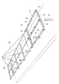
- FIG. 22 is a perspective view showing a state in which a plurality of flat structure mounts are stacked.
- FIG. 23 is a cross-sectional view showing a state in which the arm collar and the vertical rail collar are sandwiched between clips.
- FIG. 24 is a perspective view showing a state where a flat structure mount is lifted by a crane.
- FIG. 25 is a side view showing a state in which each arm is opened obliquely with respect to the vertical beam, and the column is passed through the vertical beam via the arm brackets at the end of each arm.
- FIG. 26 is a perspective view showing a fixing fitting disposed on the light receiving surface side of the solar cell module.
- FIG. 27 is a partially enlarged perspective view showing a state in which the solar cell module is attached to the middle horizontal rail using the first support bracket and the fixing bracket as viewed from above.
- FIG. 28 is a partially enlarged perspective view showing a state in which the solar cell module is attached to the middle horizontal rail using the first support bracket and the fixing bracket as viewed from below.
- FIG. 29 is a partially enlarged perspective view showing a state in which the protruding pieces of the fixing bracket are inserted between the frame members of the solar cell modules adjacent to the left and right.
- FIG. 27 is a partially enlarged perspective view showing a state in which the solar cell module is attached to the middle horizontal rail using the first support bracket and the fixing bracket as viewed from above.
- FIG. 28 is a partially enlarged perspective view showing a state in which the solar cell module is attached to the middle horizontal rail using the first support bracket and the fixing bracket as viewed from below
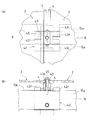
- FIG. 30A is a plan view partially showing a state in which the left and right solar cell modules are attached to the upper and lower horizontal rails using the second support bracket and the fixing bracket
- FIG. FIG. 30 is a cross-sectional view taken along the line BB in FIG.
- FIG. 31 is a side view showing a structure mount according to another embodiment.
- FIG. 1 is a perspective view showing a structural stand according to an embodiment of the present invention and a photovoltaic power generation system that supports a plurality of solar cell modules using the structural stand.
- This solar power generation system is premised on application to a power plant and comprises a large number of solar cell modules.
- a plurality of support pillars 11 are erected on the ground with a space between each other, and a plurality of vertical bars 14 are connected to an upper end portion of each support pillar 11 while being inclined, Two arms 12 and 13 are bridged between the vertical rails 14 and connected.
- the vertical bars 14 are supported on the upper ends of the columns 11.
- a plurality of the vertical bars 14 are arranged in parallel with an interval between them, and the three horizontal bars 15 are arranged so as to be orthogonal to the vertical bars 14.
- a plurality of horizontal rails 15 are juxtaposed on each vertical rail 14.
- a plurality of solar cell modules 2 are bridged between the horizontal bars 15 in an inclined state, and both ends of the solar cell modules 2 are fixed on the horizontal bars 15.
- the vertical beam 14 is provided with a pair of arm connecting members 16 protruding below the vertical beam 14.
- the arms 12 and 13 are connected to the downward projecting portions of the arm connecting members 16.
- each arm 12, 13 is connected between the body of the column 11 and the end of the two arms 12, 13 with an arm bracket 22 interposed therebetween.
- the trunk portion of the support column 11 is supported between the arm brackets 22.
- a crosspiece bracket 21 is interposed between the upper end portion of the support column 11 and the vertical beam 14, and the upper end portion of the support column 11 and the vertical beam 14 are connected by the crosspiece bracket 21.
- a plurality of solar cell modules 2 are mounted in a horizontal row between the lower horizontal beam 15 and the middle horizontal beam 15, and a plurality of solar cell modules are also interposed between the middle horizontal beam 15 and the upper horizontal beam 15. 2 are mounted in a horizontal row. Accordingly, a plurality of solar cell modules 2 are mounted in two rows on the three horizontal rails 15. Further, four or six solar cell modules 2 are disposed between two vertical bars 14 adjacent to each other on the left and right.
- the direction in which the columns 11 are arranged is the X direction (left-right direction), and the direction orthogonal to the X direction is the Y direction (front-rear direction).
- FIG. 2 is a perspective view showing the solar cell module 2.
- the solar cell module 2 includes a solar cell panel 3 that photoelectrically converts sunlight, and a frame member 4 that borders and holds the solar cell panel 3.
- the frame member 4 is made of an aluminum material, and is for securing the strength of the solar cell module 2 itself or protecting the solar cell panel 3.
- the structure mount 5 includes a support column 11 and two arms 12 and 13, a vertical beam 14, a horizontal beam 15, an arm connecting member 16, a beam bracket 21, an arm bracket 22, and the like shown in FIG. 1. Composed.
- FIG. 3 is a perspective view showing the support 11.
- pillar 11 is a steel material of the H-shaped cross-section which consists of a web part 11b which connects a pair of flange parts 11a and each flange part 11a which mutually oppose.
- two elongated holes 11c extending in the longitudinal direction of the support column 11 are formed in the web portion 11b.
- Each column 11 is driven perpendicular to the ground and protrudes at substantially the same height.
- FIGS. 4A and 4B are perspective views showing the two arms 12 and 13, respectively. As shown in FIGS. 4A and 4B, the arms 12 and 13 have different lengths. In FIG. 1, the arm 12 connected to the lower portion of the vertical beam 14 is short, and the arm 13 connected to the upper portion of the vertical beam 14 is long.
- the arms 12 and 13 have main plates 12b and 13b, a pair of side plates 12a and 13a bent on both sides of the main plates 12b and 13b, and respective flanges 12c and 13c bent outward on one side of the side plates 12a and 13a. .
- the arms 12 and 13 have a substantially hat-shaped cross-sectional shape. Further, at both ends of each arm 12 and 13, the flanges 12c and 13c are cut off, and the respective perforations 12d and 13d are formed in the side plates 12a and 13a.
- FIG. 5 is a perspective view showing the vertical rail 14.
- the vertical rail 14 has a main plate 14b, a pair of side plates 14a bent on both sides of the main plate 14b, and a flange 14c bent outward on one side of each side plate 14a.
- the vertical beam 14 has a substantially hat-shaped cross-sectional shape.
- a pair of T-shaped holes 14d are formed in the vicinity of both ends and the center of the main plate 14b of the vertical beam 14, respectively.
- elongated holes 14e are formed along the longitudinal direction of the vertical rails 14 in the central portion, the front end portion, and the rear end portion of each side plate 14a.
- FIG. 6 is a perspective view showing the crosspiece 15.
- the cross rail 15 has a main plate 15b, a pair of side plates 15a bent on both sides of the main plate 15b, and a flange 15c bent outward on one side of each side plate 15a, and its cross-sectional shape. Is generally hat-shaped. Perforations 15d and slits 15g are formed in each side plate 15a of the horizontal beam 15 at an appropriate interval, and a pair of slits 15h and opening holes 15i are formed in the main plate 15b of the horizontal beam 15 at the same interval. Has been. Further, each of the eaves 15c of the horizontal beam 15 is formed with an elongated hole 15k with an interval between the vertical beams 14 provided therebetween.
- the horizontal beam 15 is configured by connecting a plurality of beam members.
- FIG. 7 is a perspective view showing the arm connecting member 16.
- the arm connecting member 16 has a main plate 16b and a pair of side plates 16a bent on both sides of the main plate 16b, and its cross-sectional shape is generally C-shaped.
- Each side plate 16a of the arm connecting member 16 is formed with two screw holes 16c and two perforations 16d.
- the separation width on the outer side of each side plate 16a is the same or slightly narrower than the separation width on the inner side of each side plate 14a of the vertical beam 14, and each side plate 16a of the arm connecting member 16 is connected to each side plate 14a of the vertical beam 14. It is possible to insert inside.
- FIG. 8 is a perspective view showing the crosspiece bracket 21.
- the crosspiece bracket 21 includes a main plate 21b, each side plate 21a bent on both sides of the main plate 21b, and each flange 21c bent outward on one side of each side plate 21a.
- the cross-sectional shape is generally a hat shape.
- each flange 21c is cut off.
- Each side plate 21a has a perforation 21d, and each flange 21c has a screw hole 21e.
- each side plate 21a is the same as or slightly narrower than the separation width on the inner side of each side plate 14a of the vertical beam 14, so that each side plate 21a of the beam bracket 21 is connected to the inner side of each side plate 14a of the vertical beam 14. It is possible to plug in.
- FIG. 9 is a perspective view showing the arm bracket 22.
- the arm bracket 22 includes a main plate 22b, each side plate 22a bent on both sides of the main plate 22b, each L-shaped portion 22c bent on one side of each side plate 22a, and further bent into an L shape.
- Each coupling plate 22d is bent at one side of each L-shaped portion 22c.
- Each side plate 22a has a perforation 22e, and each coupling plate 22d has a perforation 22f or a screw hole 22g.
- each side plate 22a The separation width on the outside of each side plate 22a is the same as or slightly narrower than the separation width on the inside of each side plate 12a, 13a of each arm 12, 13, and each side plate 22a of the arm bracket 22 is connected to each arm 12, 13 It can be inserted into the side plates 12a and 13a. Further, the inside of each L-shaped portion 22 c of the arm bracket 22 is shaped and sized so that each flange portion 11 a of the support column 11 is fitted.
- each of the arms 12 and 13, the vertical beam 14, and the horizontal beam 15 each includes a main plate, each side plate bent on both sides of the main plate, and a hat made of each side plate bent outward on one side of each side plate. It has a mold cross-sectional shape. Moreover, all hat-shaped cross-sectional shapes are the same size. Further, both are formed by cutting or punching a plated steel sheet having the same thickness and then bending the plated steel sheet. For this reason, the material and the processing apparatus can be shared, and the cost can be significantly reduced.
- FIG. 10 is a side view showing the truss structure.
- 11 and 12 are a side view and a cross-sectional view showing, in an enlarged manner, a connecting portion between the vertical beam and the arm bracket.
- the center portion of the vertical beam 14 is connected to the upper end portion 11d of the column 11 via the beam bracket 21, and one end of the arm 12 is positioned near the tip of the vertical beam 14.
- the arm connecting member 16 one end of the arm 13 is connected to a portion near the rear end of the vertical beam 14, and the other end of each arm 12, 13 is connected to the other end of each arm 12, 13. It is connected to the trunk portion 11 e of the support column 11 via two arm brackets 22.
- the side plates 21 a of the beam bracket 21 are inserted and overlapped inside the side plates 14 a of the vertical beam 14, and pipes are connected between the side plates 21 a of the beam bracket 21.
- the pipe 25 the perforations 21d of the side plates 21a of the crosspiece bracket 21 and the elongated holes 14e of the side plates 14a of the vertical crosspiece 14 are aligned, and the bolts 26 are connected to the pipe 25 and the side plates of the crosspiece bracket 21.
- crosspiece bracket 21 Since the crosspiece bracket 21 is supported by one bolt 26 with respect to each side plate 14a of the vertical crosspiece 14, it can rotate around the bolt 26.
- the upper portions of the side plates 16 a of the arm connecting member 16 are inserted and overlapped with the inner sides of the side plates 14 a of the vertical beam 14. Are screwed into the screw holes 16c of the side plates 16a of the arm connecting member 16 via the elongated holes 14e of the side plates 14a of the vertical beam 14, and the arm connecting member 16 is connected.
- each arm connecting member 16 connected to the respective portions near the front end and the rear end of the vertical beam 14 has a lower portion protruding downward from the vertical beam 14.
- the downward projecting portions of the side plates 16 a of the arm connecting member 16 are inserted inside the side plates 12 a of the arm 12 and overlapped.
- a pipe 25 is inserted between each side plate 16a of the arm connecting member 16, and a bolt 26 is passed through the pipe 25, a perforated hole 16d in each side plate 16a of the arm connecting member 16, a perforated 12d in each side plate 12a of the arm 12, and a washer.
- a nut 27 is screwed into one end of the bolt 26 and tightened, and one end of the arm 12 is connected to the downward projecting portion of the arm connecting member 16.
- one end portion of the arm 13 is connected to the downward projecting portion of the arm connecting member 16 using the pipe 25, the bolt 26, and the nut 27. ing.
- the arms 12 and 13 are supported by the bolts 26 with respect to the downward projecting portions of the arm connecting members 16, so that the arms 12 and 13 can rotate around the bolts 26.
- the side plates 22a of the arm bracket 22 are inserted into the inner sides of the side plates 12a of the arm 12 and overlapped, as in FIG. Pipes 25 are inserted between the side plates 22a, and bolts 26 are passed through the pipes 25, the perforations 22e of the side plates 22a of the arm bracket 22, the perforations 12d of the side plates 12a of the arm 12, and washers.
- a nut 27 is screwed in and the other end of the arm 12 is connected to the arm bracket 22.
- the other end portion of the arm 13 is connected to the arm bracket 22 by using the pipe 25, the bolt 26, and the nut 27 also at the other end portion of the arm 13 connected to the trunk portion 11 e of the column 11.
- each arm bracket 22 Since each arm bracket 22 is supported by each bolt 26 with respect to each side plate of each arm 12, 13, it can rotate around each bolt 26.
- connection between the vertical beam 14 and the beam bracket 21 the connection between the downward projecting portion of each arm coupling member 16 and one end of each arm 12, 13, and the other end of each arm 12, 13 and each arm bracket 22.
- the connection between them is made using a pipe 25, a bolt 26, and a nut 27.
- the flanges 21 c of the beam bracket 21 of the vertical beam 14 are overlapped with the web portion 11 b of the column 11 with the central portion of the vertical beam 14 placed on the upper end portion 11 d of the column 11.
- the screw holes 21e of the flanges 21c of the crosspiece bracket 21 are overlapped with the long holes 11c of the web portion 11b, and two bolts 28 are connected to the flanges of the crosspiece bracket 21 through the long holes 11c of the web portion 11b.
- the crosspiece bracket 21 is fixed to the upper end portion 11d of the column 11 by screwing it into the screw hole 21e of 21c, and the central portion of the vertical beam 14 is connected to the upper end portion 11d of the column 11 via the crosspiece bracket 21.
- the arm brackets 22 of the arms 12 and 13 are opposed to each other via the support column 11, and the flange portions 11a of the support column 11 are fitted inside the L-shaped portions 22c of each of the arm brackets 22.
- Each coupling plate 22d of one arm bracket 22 and each coupling plate 22d of the other arm bracket 22 are overlapped.
- the perforations 22f and the screw holes 22g of each one of the coupling plates 22d are opposed to the screws 22g and the perforations 22f of the other coupling plate 22d, so that the two bolts 29 are connected to the respective screws 22g through the respective perforations 22f.
- the arm brackets 22 can be connected to each other by screwing and tightening, whereby the flange portions 11a of the support column 11 can be sandwiched and supported inside the L-shaped portions 22c of both arm brackets 22. That is, the column 11 is sandwiched and supported between the arm brackets 22.
- the central portion of the vertical beam 14 is connected to the upper end portion 11d of the column 11 via the beam bracket 21, and the arms 12 and 13 are connected to the trunk portion 11e of the column 11 via each arm bracket 22. To do.
- Such a truss structure including the support columns 11, the two arms 12 and 13, and the vertical beam 14 is provided in order to increase the strength of the structure mount 5 according to the present embodiment.
- the solar cell module 2 on the vertical beam 14 is stably provided. Can be supported. Further, as shown in FIG. 1, since the two rows of solar cell modules 2 are distributed on both sides of the central portion of the vertical beam 14, the load of each solar cell module 2 hardly acts so as to tilt the column 11. Further, the stability of the structure mount of the present embodiment is further improved.
- the height of the vertical beam 14 on each column 11 can be adjusted. Even if there is a variation in the height of each column 11, there should be no variation in the height (vertical position) of the vertical beam 14 on each column 11, and the height of each vertical beam 14 can be adjusted. Need to be prepared. For this purpose, the two bolts 28 are loosened so that the crosspiece bracket 21 can be moved in the direction of each elongated hole 11c of the web portion 11b of the column 11, and the bolts 29 are loosened so that each arm bracket 22 is moved. In addition, the arms 12 and 13 can be moved along the support column 11, and the vertical rail 14 can be moved in the vertical direction.
- the bolts 28 and 29 are tightened to fix the beam bracket 21, the arm bracket 22, and the arms 12 and 13, and the vertical beam 14 is also fixed. . Thereby, the height of each vertical rail 14 can be adjusted and aligned.
- each vertical rail 14 in the Y direction can be adjusted.
- the bolts 26 that fasten the central portion of the vertical beam 14 and the beam bracket 21 are loosened, the bolts 24 that fasten the portion near the tip of the vertical beam 14 and the upper portion of the arm connecting member 16 are loosened, and the vertical beam 14
- the bolt 24 which fastens the part near the rear end and the upper part of the arm connecting member 16 is loosened, and the vertical beam 14 is connected to each bolt 24, 26 with the elongated hole of each side plate 14 a of the vertical beam 14. 14e so that it can move along.
- the bolts 24 and 26 are tightened to fix the vertical beam 14.
- the position of each vertical rail 14 in the Y direction can be adjusted and aligned.
- FIG. 13 is a perspective view showing a mounting bracket 31 used for connecting and fixing the horizontal beam 15 to the vertical beam 14. As shown in FIG. 13, the mounting bracket 31 protrudes from the center of the main plate 31a, each side plate 31c folded on both sides of the main plate 31a, each side plate 31d folded back before and after the main plate 31a, and each side plate 31d. Each T-shaped support piece 31e is provided. Two screw holes 31b are formed in the main plate 31a.
- a pair of T-shaped holes 14d are formed in the vicinity of both ends and the center of the main plate 14b of the vertical beam 14, respectively.
- the mounting bracket 31 is mounted on the main plate 14b of the vertical beam 14, and the respective mounting brackets 31 are arranged near the both ends of the main plate 14b of the vertical beam 14 and in the central portion.
- each support piece 31e of the mounting bracket 31 is inserted into the slit 14g of each T-shaped hole 14d, and each support piece 31e is moved to the engagement hole 14h of each T-shaped hole 14d. Then, the mounting bracket 31 is attached to the main plate 14b of the vertical beam 14 by hooking the heads of the respective support pieces 31e into the engagement holes 14h of the respective T-shaped holes 14d.
- the horizontal beam 15 is placed on the main plate 14b of the vertical beam 14 so as to be orthogonal to the vertical beam 14, and each bar 15c of the horizontal beam 15 is attached to the head of each support piece 31e of the mounting bracket 31. Place between. Then, the long holes 15k of the flanges 15c of the horizontal beam 15 are overlapped with the screw holes 31b of the mounting bracket 31 via the T-shaped holes 14d of the main plate 14b of the vertical beam 14, and the bolts 32 are respectively connected to the horizontal beams 15. It is screwed into each screw hole 31b of the mounting bracket 31 via the long hole 15k of the flange 15c and each T-shaped hole 14d of the main plate 14b of the vertical rail 14 and temporarily fixed.
- each bolt 32 can be moved along the long hole 15k of each flange 15c of the horizontal beam 15, so that the horizontal beam 15 is moved along each long hole 15k (X in FIG. 1). To adjust the position of the crosspiece 15 in the X direction.
- the mounting bracket 31 can be moved along each T-shaped hole 14 d of the main plate 14 b of the vertical beam 14 (in the longitudinal direction of the vertical beam 14), and the horizontal beam 15 can be moved together with the mounting bracket 31. .
- the horizontal beam 15 By the movement of the horizontal beam 15 in the longitudinal direction of the vertical beam 14, the interval between the three horizontal beams 15 arranged on the vertical beam 14 is adjusted.
- the middle horizontal beam 15 supports the end of the upper and lower solar cell modules 2, and the upper and lower horizontal beams 15 support the end of the upper or lower solar cell module 2. I support it. For this reason, the support structure of the solar cell module 2 is different between the middle horizontal rail 15 and the upper and lower horizontal rails 15, and the first and second support fittings are used properly.
- FIG. 16 is a perspective view showing a first support fitting for connecting and fixing the solar cell module 2 to the middle horizontal rail 15.
- the first support fitting 41 has a side plate 41a, a main plate 41b bent at the upper edge of the side plate 41a, and a bottom plate 41c bent at the lower edge of the side plate 41a.
- the main plate 41b is formed with projections 41d that are bent and raised at both corners of the main plate 41b.
- Each protrusion 41d draws an arc that is curved so as to go through both corners of the main plate 41b when viewed from above.
- a screw hole 41e is formed in the approximate center of the main plate 41b.
- a perforation 41f is formed in the side plate 41a, a C-shaped cut is formed in the side plate 41a, and an inner portion of this cut is raised to form an engagement piece 41g.
- the height of the side plate 41a is substantially equal to the height of the side plate 15a of the horizontal rail 15.
- the first support fittings 41 are arranged in pairs at the positions where the perforations 15d and the slits 15g are formed in the side plates 15a of the middle horizontal rail 15, and the two first support fittings 41 are provided as shown in FIG.
- the engaging pieces 41g of the side plates 41a of the respective first support brackets 41 are engaged with the slits 15g of the respective side plates 15a of the lateral rails 15 so as to be temporarily fixed.
- the main plate 41 b of each first support fitting 41 protrudes outward from the horizontal beam 15, and each protruding piece 41 d of each first support fitting 41 protrudes above the main plate 15 b of the horizontal beam 15.
- the pipe 25 is inserted between the side plates 15a of the horizontal rail 15, and the pipe 25, the perforations 15d of the side plates 15a of the horizontal rail 15, and the side plates 41a of the first support fittings 41 are provided.
- the bolt 26 is passed through the pipe 25, the hole 15 d of each side plate 15 a of the crosspiece 15, the hole 41 f of the side plate 41 a of each first support fitting 41, and a washer, and a nut is attached to one end of the bolt 26. 27 is screwed and tightened to fix the first support fittings 41 to the middle horizontal rail 15.
- FIG. 18 is a perspective view showing a second support fitting for connecting and fixing the solar cell module 2 to the upper and lower horizontal rails 15.
- the second support fitting 42 includes a pair of side plates 42 a facing each other, a main plate 42 b that connects opposite sides of each side plate 42 a, and each flange that bends at the edge of each side plate 42 a and protrudes outward. It has a hat-shaped cross-sectional shape made of 42c, and is set to a shape and size that fit inside the horizontal rail 15.
- each side plate 42a of the second support fitting 42 is formed with a screw hole 42d
- a screw hole 42e is formed on the center line of the main plate 42b
- each elongated hole 42g is formed with a long hole 42g. .
- Such second support fittings 42 are respectively arranged at positions where the pair of slits 15h and the opening holes 15i are formed in the main plate 15b of the upper and lower horizontal rails 15 and are fitted inside the horizontal rails 15.
- the protruding pieces 42 f of the main plate 42 b of the second support fitting 42 are formed from the pair of slits 15 h of the main plate 15 b of the horizontal beam 15. Projects upward.
- each side plate 42a of the second support fitting 42 overlaps with each side plate 15a of the horizontal rail 15, the main plate 42b of the second support fixture 42 overlaps with the main plate 15b of the horizontal rail 15, and each flange 42c of the second support fixture 42 It overlaps with each fence 15c of the horizontal rail 15.
- the two bolts are respectively screwed into the screw holes 42d of the side plates 42a of the second support fittings 42 through the perforations 15d of the side plates 15a of the horizontal rails 15, and the second support fittings 42 are tightened.
- the main plate, the side plate, and the heel have a double structure at the portion of the second support fitting 42, and the strength at this portion is increased.
- the structural mount 5 of the present embodiment has almost all of the members other than the support column 11, that is, the arms 12 and 13, the vertical beam 14, the horizontal beam 15, the arm connecting member 16, the beam bracket 21, and the arm bracket 22. It is assumed that the first and second support fittings 41, 42, etc. are assembled at the factory, a flat structure is constructed, and a plurality of flat structures are stacked and transported from the factory to the construction site.
- the vertical beam 14 and the horizontal beam 15 are assembled in a ladder shape as is apparent from FIG. 1, they are flat structures and can be stacked.
- the crosspiece bracket 21 protrudes below the vertical crosspiece 14.
- Each arm 12, 13 protrudes downward from the vertical beam 14, and each arm bracket 22 is separated from the vertical beam 14.
- the crosspiece bracket 21, the arms 12 and 13, and the arm brackets 22 make it impossible to stack a flat structure composed of the vertical crosspiece 14 and the horizontal crosspiece 15.
- the arms 12 and 13, the crosspiece bracket 21, and the arm bracket 22 can be folded to form a flat structure.
- the member 6 is used.
- the crosspiece bracket 21 can be rotated around a bolt 26 that supports the crosspiece bracket 21, and the crosspiece bracket 21 can be placed inside each side plate 21 of the vertical crosspiece 14.
- the arms 12 and 13 are rotated around the bolts 26 that support the arms 12 and 13, and the arms 12 and 13 are closed in parallel with the vertical beam 14.
- the arm brackets 22 are rotated around the respective bolts 26 that support the arm brackets 22, and the vertical rails 14 can be accommodated inside the arm brackets 22.
- each side plate 21a of the crosspiece bracket 21 is inserted inside each side plate 14a of the vertical crosspiece 14 and the crosspiece bracket 21 is pivotally supported by one bolt 26, the crosspiece bracket 21 is rotated around the bolt 26.
- the crosspiece bracket 21 is rotated until the side plates 21a and the flanges 21c of the crosspiece bracket 21 are overlapped with the side plates 14a and the flanges 14c of the vertical crosspiece 14, so that the crosspiece bracket 21 is moved to the side plates 21 of the vertical crosspiece 14. Can fit inside.
- each side plate 16a of the arm connecting member 16 is inserted inside each side plate 12a of the arm 12 and the arm 12 is pivotally supported by one bolt 26, the arm 12 can be rotated around the bolt 26.
- the arm 12 can be rotated until each rod 12c of the arm 12 overlaps each rod 14c of the vertical beam 14, and the arm 12 can be closed in parallel with the vertical beam 14.
- each side plate 16a of the arm connecting member 16 is inserted inside each side plate 12a of the arm 13 and the arm 13 is pivotally supported by one bolt 26, each flange 13c of the arm 13 is connected to the vertical rail 14
- the arm 13 can be rotated until it overlaps with each of the ridges 14c, and the arm 13 can be closed in parallel with the vertical beam 14.
- the distance between the pivot support positions of the arms 12 and 13 by the bolts 26 is L, and the length from the pivot support position of the arm 12 by the bolts 26 to the end of the arm 12 is L1.
- L2 L> (L1 + L2) L, L1, and L2 are set so that For this reason, between each bolt 26, each arm 12 and 13 can be arranged in parallel with the vertical rail 14, and can be closed, and each arm 12 and 13 can be arranged in a straight line.
- each side plate 22a of the arm bracket 22 is inserted inside each side plate 12a of the arm 12 or inside each side plate 13a of the arm 13, and the arm bracket 22 is pivotally supported by one bolt 26.
- the arm bracket 22 can be directed toward the vertical rail 14.
- the inside of each L-shaped portion 22c of the arm bracket 22 is not only in a shape and size so that each flange portion 11a of the column 11 is fitted, but also in a size in which each flange 14c of the vertical beam 14 is inserted. But there is. For this reason, when the arm bracket 22 is directed toward the vertical beam 14, the vertical beam 14 can be accommodated inside each L-shaped portion 22 c of the arm bracket 22.
- the state shown in FIG. 21 is a state in which the longitudinal beam 14 and the arms 12 and 13 are overlapped so that the longitudinal direction of the longitudinal beam 14 and the arms 12 and 13 are aligned and the arms 12 and 13 are aligned in a straight line.
- the state shown in FIG. 20 can be said to be a state in which the opposite ends of the arms 12 and 13 are separated from the vertical rail 14 from the state shown in FIG. Therefore, the arm connecting member 16 is formed by connecting the outer ends of the arms 12 and 13 to the vertical rail 14 so as to be movable between these two states.
- the crosspiece bracket 21 is placed inside each side plate 21a of the vertical crosspiece 14, the arms 12 and 13 are closed so as to be parallel to the vertical crosspiece 14, and the arms 12, 13 and the vertical crosspiece 14 are overlapped.
- the maximum thickness of the member 6 is the sum of the height of the vertical beam 14 and the height of the arm 12 or 13, and the beam bracket 21, the arms 12, 13, and the arm brackets 22 are not bulky. Becomes a flat structure. For this reason, it becomes possible to stack and transport the plurality of gantry members 6.
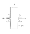
- the use of the clip 48 that sandwiches the overlapping ridges 12c and 13c and the ridge 14c together allows the arms 12 and 13 to be kept closed.
- the gantry member 6 includes the arms 12 and 13, the arm connecting member 16, the arm bracket 22, and the crosspiece bracket 21, but may include the horizontal crosspiece 15.
- FIG. 22 shows a state where a plurality of gantry members 6 including the cross rail 15 are mounted and transported on the loading platform of the trailer 61.
- a plurality of support pillars 11 are arranged in a straight line at equal intervals so as to project from the ground.
- the interval between the columns 11 is equal to the arrangement interval of the vertical bars 14 of the structure mount 5.
- a plurality of flat gantry members 6 are stacked and mounted on the loading platform of the trailer 61, and these gantry members 6 are transported to the site.
- a plurality of wires 46 are hooked on the flat gantry member 6 on the loading platform of the trailer 61, and the flat gantry member 6 is lifted via the wire 46 by a crane.
- the gantry member 6 is moved to the upper side of each column 11, the horizontal beam 15 of the gantry member 6 is aligned in the direction of the alignment of the columns 11, and the central portion and each column of each vertical beam 14 of the gantry member 6 are arranged. 11 is aligned. Further, the vertical bars 14 of the gantry member 6 are inclined at substantially the same angle as in FIG.
- each vertical beam 14 of the gantry member 6 the clip 48 of FIG. 23 is removed, and as shown in FIG. 25, the arms 12 and 13 are opened obliquely with respect to the vertical beam 14, and the gantry member 6 is lowered,
- the strut 11 is passed between the arm brackets 22 at the ends of the arms 12 and 13 and passed through the vertical beam 14, and the center of the vertical beam 14 is placed on the upper end 11d of the column 11 as shown in FIG.
- Each rod 21c of the beam bracket 21 of the vertical beam 14 is overlapped with the web portion 11b of the support column 11, and two bolts 28 are screwed through the elongated holes 11c of the web portion 11b to the screw holes 21e of each beam 21c of the beam bracket 21.
- the central portion of the vertical beam 14 is connected to the upper end portion 11 d of the column 11 via the beam bracket 21.
- the arm brackets 22 of the arms 12 and 13 are opposed to each other through the support column 11, and the coupling plates 22d of the one arm bracket 22 and the coupling plates 22d of the other arm bracket 22 are overlapped with each other. 29 is screwed into a screw 22g of each other coupling plate 22d through a hole 22f in each coupling plate 22d and fastened, and the support 11 is sandwiched and supported between each arm bracket 22. Thereby, the structure mount 5 is completed.
- the length L2 is set so that L> (L1 + L2), so that the length of each arm 12, 13 is insufficient with only the vertical rail 14 and each arm 12, 13, and the truss structure is reduced.
- two arm brackets 22 are interposed between the ends of the arms 12 and 13, and the ends of the arms 12 and 13 are separated from each other. Supplemented, a truss structure can be built.
- FIG. 26 is a perspective view showing a fixing bracket arranged on the light receiving surface side of the solar cell module 2.
- the fixing metal 43 is formed by forming a protruding piece 43b bent downward at the front and rear ends of the pressing plate 43a and forming a perforation 43c at the center of the pressing plate 43a.
- FIGS. 27 and 28 are perspective views showing a state in which each solar cell module 2 is attached to the middle horizontal rail 15 using the first support fitting 41 and the fixing fitting 43 as seen from above and below. As shown in FIGS. 27 and 28, the frame member 4 of each solar cell module 2 is placed between the projecting pieces 41 d of the first support fitting 41 and placed on the main plate 15 b of the horizontal rail 15.
- the protrusions 43b of the fixing bracket 43 are inserted between the frame members 4 of the solar cell modules 2 adjacent to each other on the left and right sides, and the frame members 4 of the solar cell modules 2 are separated by a predetermined interval.
- the bolts 45 are screwed into the screw holes 41e of the main plate 41 of the first support fitting 41 through the perforations 43c of the fixing fitting 43 and the gaps between the frame members 4 of the solar cell modules 2 and tightened.
- the frame member 4 of each solar cell module 2 is sandwiched and fixed between the fixture 43 and the main plate 15b of the horizontal rail 15.
- FIGS. 30A and 30B are plan views showing a state in which the two left and right solar cell modules 2 are attached to the upper and lower horizontal rails 15 using the second support bracket 42 and the fixing bracket 43.
- FIG. FIG. As shown in FIGS. 30A and 30B, the frame members 4 of the left and right solar cell modules 2 are placed between the projecting pieces 42f of the second support fitting 42 and mounted on the main plate 15b of the cross rail 15. Put. And each projection piece 43b of the fixing metal fitting 43 is inserted between the frame members 4 of the left and right solar cell modules 2, and the frame members 4 of the solar cell modules 2 are separated by a predetermined interval.
- the bolt 45 is screwed into the screw hole of the main plate 42 of the second support fitting 42 through the hole 43c of the fixing bracket 43, the gap between the frame members 4 of each solar cell module 2, and the opening hole 15i of the main plate 15b of the horizontal rail 15. Screw into 42e and tighten. As a result, the frame member 4 of each solar cell module 2 is sandwiched and fixed between the fixture 43 and the main plate 15b of the horizontal rail 15.
- the outer end of the arm 12 (or 13) is rotatably supported by the downward projecting portion of each side plate 16a of the arm connecting member 16, and the arm 12 (or 13) is closed in parallel with the vertical beam 14.
- the arm 12 (or 13) and the vertical rail 14 can be overlapped, but instead, the outer end portion of the arm 12 (or 13) is used as a downward projecting portion of each side plate 16a of the arm connecting member 16.
- the arm 12 (or 13) is fixed so that the upper portion of each side plate 16a of the arm connecting member 16 is pivotally supported on the vertical beam 14 so that the arm 12 (or 13) is closed in parallel with the vertical beam 14.
- the vertical rail 14 may be allowed to overlap.
- each side plate 12a (or 13a) of the arm 12 (or 13) is extended to the inside of each side plate 14a of the vertical rail 14, and the end of each side plate 12a (or 13a) of the arm 12 (or 13).
- the portion may be pivotally supported by each side plate 14 a of the vertical beam 14.
- the arm 12 (or 13) may be connected to the lower surface of each bar 14c of the vertical beam 14 via a hinge.
- a columnar column 11A as shown in FIG. 31 may be applied.
- a wall h is projected from the upper end surface 11g of the support 11A, the crosspiece bracket 21 is fastened to the wall h, and each arm bracket 22A suitable for sandwiching the support 11A is applied.
- an arc-shaped concave portion for sandwiching the column 11A is formed inside each arm bracket 22A.
- the present invention can be suitably used for a solar power generation system.
Landscapes
- Engineering & Computer Science (AREA)
- Mechanical Engineering (AREA)
- Physics & Mathematics (AREA)
- Life Sciences & Earth Sciences (AREA)
- Sustainable Development (AREA)
- Sustainable Energy (AREA)
- Thermal Sciences (AREA)
- Chemical & Material Sciences (AREA)
- Combustion & Propulsion (AREA)
- General Engineering & Computer Science (AREA)
- Photovoltaic Devices (AREA)
- Roof Covering Using Slabs Or Stiff Sheets (AREA)
Abstract
架台用部材(6)は、桟(14)と、桟(14)を支持する支柱に接続するための2本のアーム(12,13)と、一対のアーム連結部材(26)とを備えている。前記アーム連結部材(26)は、2本のアーム(12,13)の外側端部を桟(14)に連結する。前記アーム連結部材(26)は、桟(14)と2本のアーム(12,13)との長手方向が揃いかつ2本のアーム(12,13)が直線状に並ぶように桟(14)と2本のアーム(12,13)とが重ねられた状態と、その状態から2本のアーム(12,13)の互いに対向する端部が桟(14)と離間した状態との、2つの状態の間で可動となる。
Description
本発明は、太陽電池モジュール等の構造物を支持するための架台用部材、構造物用架台、その架台の施工方法、及びその架台を用いた太陽光発電システムに関する。
太陽電池モジュール等の構造物を支持するための架台としては、平行に並んだ複数の桟の間に複数の太陽電池モジュールを架け渡して、各太陽電池モジュールを支持する構造のものが知られている。
この種の架台は、複数の桟、各桟を支持する複数の支柱、及び各桟を支柱に連結する複数のアーム等の多くの部品からなるので、現場での組み立て作業に手間と時間を要していた。そのため、工場で桟の組み立てを行ってから現場に搬送し、その桟を現場にて支柱にアームを介して連結し、架台を完成させることもなされていた。
また、例えば特許文献1には、ゴム製の基板、補強層、及び粘着層を積層したルーフィング材に予め接続端子や配線を設けておき、そのルーフィング材を屋根上に固定し、ルーフィング材上に複数の太陽電池モジュールを並設して接続する構成が開示されている。
しかしながら、従来は、工場で組み立てた桟を、現場にて前記アームを介して支柱に連結して現場での組み立て作業を簡略化しているものの、この連結作業が困難であることから、現場での作業の更なる簡略化が望まれていた。
例えば、アーム及び桟をともに工場で組み立ててから現場に搬送すれば、現場での組み立て作業を更に簡略化することができる。複数の桟を組み立てた段階では、各桟がはしご状の平坦な構築物となる。よって、この段階で現場へ搬送する場合、この平坦な構築物を積み重ねて容易に輸送することができる。しかし、桟とアームとを組み立てると、前記平坦な構築物に複数のアームが取り付けられ、その構築物が平坦ではなくなる。そうすると、搬送時には嵩張ってしまい、積み重ねられず、搬送が困難となることがあった。
また、前記特許文献1に開示されたルーフィング材は、屋根のような平坦面に広げられることが前提であり、複数の桟や支柱からなる架台上に設置することはできず、架台の組み立て作業の簡略化を実現するものではない。
そこで、本発明は、上記従来の問題点に鑑みてなされたものであり、平坦な構築物として輸送することができ、現場での組み立て作業を大幅に簡略化することが可能な架台用部材、構造物用架台、その架台の施工方法、及びその架台を用いた太陽光発電システムを提供することを目的とする。
上記課題を解決するために、本発明に係る架台用部材は、構造物を支持する架台用部材であって、桟と、前記桟を支持する支柱に接続される2本のアームと、前記桟と前記2本のアームとの長手方向が揃いかつ前記2本のアームが直線状に並ぶように前記桟と前記2本のアームとが重ねられた状態と、その状態から前記2本のアームの互いに対向する端部が前記桟から離間した状態との2つの状態の間で可動となるように、前記2本のアームの外側端部を前記桟に連結する一対のアーム連結部材とを備えている。
このような架台用部材では、桟と2本のアームとが重ねられた状態とすれば、架台用部材の厚みがアームの厚みと桟の厚みとの和に略等しくなり、架台用部材が嵩張らず、複数の架台用部材を積み重ねることが可能になる。このため、各アームを各桟と共に工場で組み立てて、複数の架台用部材を積み重ねて輸送することができる。また、2本のアームの対向側が桟から離間した状態とすれば、各アームの対向側端部を支柱に接続することにより、桟を支柱に取り付けることができ、桟をアームを介して支柱に連結する作業が容易である。
また、前記構成の架台用部材において、前記桟を支持する支柱に、前記各アームの対向側端部を連結するそれぞれのアームブラケットを備え、前記各アームブラケットを前記各アームの対向側端部に回転可能に設けていることが好ましい。
この場合、各アームの対向側端部を、各アームブラケットを介して、支柱に接続することができる。
また、前記構成の架台用部材において、前記各アームブラケットを前記桟の側に向くように回転させて、前記各アームブラケットの内側に前記桟を納めることを可能とすることが好ましい。
これにより、桟と2本のアームとが重なり、かつ各アームブラケットの内側に桟を納めた状態では、構造物用架台が嵩張らず、複数の構造物用架台を積み重ねて輸送することができる。
また、前記構成の架台用部材においては、前記桟を支持する支柱の上に該桟を連結する桟ブラケットを備え、前記桟ブラケットを前記桟における前記各アーム連結部材の間の部位に回転可能に設けていることが好ましい。
この場合、桟を、桟ブラケットを介して、支柱の上端部に接続することができる。
また、前記構成の架台用部材においては、前記桟ブラケットを回転させて前記桟の内側に納めることを可能とすることが好ましい。
これにより、桟と2本のアームとが重なり、かつ桟ブラケットを桟の内側に納めた状態では、構造物用架台が嵩張らず、複数の構造物用架台を積み重ねて輸送することができる。
また、上記の各解決手段に係る架台用部材を備えた構造物用架台も本発明の技術的思想の範疇である。すなわち、本発明に係る構造物用架台は、前記桟を支持する支柱を備え、前記各アームの対向側端部が前記桟と離間した状態で、前記各アームの対向側端部を前記支柱に接続する構成としている。
このように各アームの対向側端部が前記桟と離間した状態で、各アームの対向側端部を支柱に接続することで、トラス構造を構築することができる。
また、前記構成の構造物用架台においては、複数組の前記桟及び前記2本のアームを備え、前記各桟をそれぞれの縦桟として、前記各縦桟を並設し、前記各縦桟上に該各縦桟と直交するように複数の横桟を並設していることが好ましい。
これにより、これらの横桟に、複数の構造物を架け渡して並設することができる。
また、前記構成の構造物用架台において、前記構造物は、太陽電池モジュールであってもよい。
また、本発明に係る架台用部材は、並設された複数の縦桟と、前記縦桟毎に設けられ、前記縦桟を支持する支柱に接続するための2本のアームと、前記縦桟毎に設けられ、前記縦桟と前記2本のアームとの長手方向が揃いかつ前記2本のアームが直線状に並ぶように前記縦桟と前記2本のアームとが重ねられた状態と、その状態から前記2本のアームの互いに対向する端部が前記縦桟と離間した状態との2つの状態の間で可動となるように、前記2本のアームの外側端部を前記縦桟に連結する一対のアーム連結部材と、前記各縦桟上に該各縦桟と直交するように並設された複数の横桟とを備えて構成されてもよい。
かかる架台用部材では、各縦桟を並設し、各横桟を各縦桟上に該各縦桟と直交するように並設し、また縦桟と前記2本のアームとが重ねられた状態とすることができる。そのため、架台用部材が平坦なものとなり、複数の架台用部材を積み重ねることができる。また、各アームを各縦桟及び各横桟と共に工場で組み立てて、複数の架台用部材を積み重ねて輸送することができる。さらに、2本のアームの対向側端部が縦桟と離間した状態とすることができるので、この状態で、各アームの対向側端部を支柱に接続すれば、縦桟を支柱に取り付けることができ、縦桟をアームを介して支柱に連結する作業が容易となる。
また、上記各解決手段に係る架台用部材を備えた構造物用架台の施工方法も本発明の技術的思想の範疇である。すなわち、本発明に係る構造物用架台の施工方法は、支柱を突設する工程と、前記桟及び前記各アームを吊り上げて前記支柱の突設位置の上方まで移動してから下降させて、前記各アームの対向側端部が前記桟と離間した状態で、前記各アームの対向側端部を前記支柱に接続する工程とを含む構成とされる。
また、本発明に係る構造物用架台の施工方法は、上記本発明の架台用部材を備えた構造物用架台の施工方法であって、前記各縦桟に対応するそれぞれの支柱を突設して配列する工程と、前記横桟で連結された複数の前記縦桟及び前記アームを吊り上げて前記支柱の突設位置の上方に移動してから下降させて、前記各アームの対向側端部が前記桟と離間した状態で、前記各アームの対向側端部を前記支柱に接続する工程とを含む構成であってもよい。
かかる施工方法では、桟及び各アーム、又は横桟で連結された複数の縦桟及びアームを吊り上げて支柱の突設位置の上部に移動してから下降させ、各アームの対向側端部が桟と離間した状態で、各アームの対向側端部を支柱に接続するので、構造物用架台の組み立て作業が、より一層容易となる。
また、上記各解決手段に係る構造物用架台を用いた太陽光発電システムも本発明の技術的思想の範疇である。すなわち、本発明に係る太陽光発電システムは、前記各横桟間に複数の太陽電池モジュールを架け渡して支持する構成としている。
このような太陽光発電システムにおいても、上記本発明に係る構造物用架台と同様の作用効果を奏することができる。
本発明によれば、桟と2本のアームとが重ねられた状態とすれば、架台用部材の厚みがアームの厚みと桟の厚みとの和に略等しくなる。そのため、架台用部材が嵩張らず、複数の架台用部材を積み重ねることが可能になる。また、各アームを各桟と共に工場で組み立てて、複数の架台用部材を積み重ねて輸送することができる。さらに、2本のアームの対向側が桟と離間した状態とすれば、各アームの対向側端部を支柱に接続することにより、桟を支柱に取り付けることができ、桟を、アームを介して支柱に連結する作業を容易に行うことができる。
以下、本発明の実施形態について、図面を参照しつつ詳細に説明する。
図1は、本発明の一実施形態に係る構造物用架台、及び前記構造物用架台を用いて複数の太陽電池モジュールを支持してなる太陽光発電システムを示す斜視図である。
この太陽光発電システムは、発電所への適用を前提としており、多数の太陽電池モジュールを備えて構成される。
図1に示すように、複数の支柱11を相互に間隔を設けて地面に立設し、各支柱11の上端部に複数の縦桟14を傾斜させて接続し、各支柱11の胴部と各縦桟14間にそれぞれ2本のアーム12、13を架け渡して接続している。これにより各支柱11の上端部に各縦桟14を支持している。縦桟14については複数本を相互に間隔を設けて平行に配置し、3本の横桟15を各縦桟14と直交させるように配設する。これにより、複数の横桟15を各縦桟14上に並設する。各横桟15間には複数の太陽電池モジュール2を傾斜状態に架け渡し、各横桟15上に各太陽電池モジュール2の両端を固定している。
縦桟14には、該縦桟14の下方に突出した一対のアーム連結部材16が設けられている。各アーム連結部材16の下方突出部分には、アーム12、13が接続されている。
支柱11の胴部と2本のアーム12、13の端部との間には、アームブラケット22を介在させて、各アーム12、13の端部が連結されている。各アームブラケット22の間に支柱11の胴部が支持されている。
支柱11の上端部と縦桟14間には桟ブラケット21が介在され、桟ブラケット21により支柱11の上端部と縦桟14が連結されている。
下段の横桟15と中段の横桟15の間に複数の太陽電池モジュール2が横一列に並べられて搭載され、中段の横桟15と上段の横桟15の間にも複数の太陽電池モジュール2が横一列に並べられて搭載されている。従って、3本の横桟15上に、複数の太陽電池モジュール2が2列に並べて搭載されている。また、左右に隣り合う2本の縦桟14間には、4枚又は6枚の太陽電池モジュール2が配設されている。
尚、図1において、各支柱11が並ぶ方向をX方向(左右方向)とし、このX方向と直交する方向をY方向(前後方向)としている。
図2は、太陽電池モジュール2を示す斜視図である。図2に示すように太陽電池モジュール2は、太陽光を光電変換する太陽電池パネル3と、この太陽電池パネル3を縁取って保持する枠部材4とで構成されている。枠部材4は、アルミ材からなり、太陽電池モジュール2そのものの強度を確保したり、太陽電池パネル3を保護したりするためのものである。
本実施形態の構造物用架台5は、図1に示す支柱11、2本のアーム12、13、縦桟14、横桟15、アーム連結部材16、桟ブラケット21、アームブラケット22等を備えて構成される。
次に、構造物用架台5を構成する支柱11、2本のアーム12、13、縦桟14、横桟15等について説明する。
図3は、支柱11を示す斜視図である。図3に示すように支柱11は、相互に対向する一対のフランジ部11a及び各フランジ部11aを連結するウエブ部11bからなるH字形断面形状の鋼材である。支柱11の上端部11dの付近で、ウエブ部11bに支柱11の長手方向に延びる2個の長形孔11cが形成されている。各支柱11は、地面に対して垂直に打ち込まれて、略同一高さに突設される。
図4(a)及び図4(b)は、2本のアーム12、13をそれぞれ示す斜視図である。図4(a)及び図4(b)に示すように、アーム12、13は、相互に長さが異なる。図1における縦桟14の傾斜下側の箇所に接続されるアーム12は短く、縦桟14の傾斜上側の箇所に接続されるアーム13は長い。
アーム12、13は、主板12b、13b、主板12b、13bの両側で折り曲げられた一対の側板12a、13a、及び各側板12a、13aの一辺で外側に折り曲げられたそれぞれの鍔12c、13cを有する。アーム12,13は略ハット型の断面形状とされている。また、各アーム12、13の両端部では、各鍔12c、13cが切除され、各側板12a、13aにそれぞれの穿孔12d、13dが形成されている。
図5は、縦桟14を示す斜視図である。図5に示すように縦桟14は、主板14b、主板14bの両側で折り曲げられた一対の側板14a、及び各側板14aの一辺で外側に折り曲げられたそれぞれの鍔14cを有している。縦桟14は、略ハット型の断面形状とされている。縦桟14の主板14bの両端近傍及び中央部には、一対のT字形孔14dがそれぞれ形成されている。また、各側板14aの中央部、先端寄りの部位、及び後端寄りの部位に、それぞれの長形孔14eが縦桟14の長手方向に沿って形成されている。
図6は、横桟15を示す斜視図である。図6に示すように横桟15は、主板15b、主板15bの両側で折り曲げられた一対の側板15a、及び各側板15aの一辺で外側に折り曲げられたそれぞれの鍔15cを有し、その断面形状が概ねハット型となっている。横桟15の各側板15aには、適宜の間隔を開けて穿孔15d及びスリット15gが形成され、また横桟15の主板15bには、同間隔を開けて一対のスリット15h及び開口孔15iが形成されている。更に、横桟15の各鍔15cには、各縦桟14の配置間隔を開けてそれぞれの長形孔15kが形成されている。
尚、横桟15がX方向に極めて長く、横桟15を単一の部材として作製するのは困難であるため、横桟15を複数の桟部材を接続して構成している。
図7は、アーム連結部材16を示す斜視図である。図7に示すようにアーム連結部材16は、主板16b、及び主板16bの両側で折り曲げられた一対の側板16aを有し、その断面形状が概ねC型となっている。アーム連結部材16の各側板16aには、2つのネジ孔16c及び2つの穿孔16dが形成されている。また、各側板16aの外側の離間幅が縦桟14の各側板14aの内側の離間幅と同一か僅かに狭くされており、アーム連結部材16の各側板16aを縦桟14の各側板14aの内側に差し込むことが可能にされている。
図8は、桟ブラケット21を示す斜視図である。図8に示すように桟ブラケット21は、主板21b、主板21bの両側で折り曲げられた各側板21a、及び各側板21aの一辺で外側に折り曲げられたそれぞれの鍔21cを有しており、それらの断面形状が概ねハット型となっている。また、桟ブラケット21の一端部では、各鍔21cが切除されている。各側板21aにそれぞれの穿孔21dが形成され、各鍔21cにそれぞれのネジ孔21eが形成されている。更に、各側板21aの外側の離間幅が縦桟14の各側板14aの内側の離間幅と同一か僅かに狭くされており、桟ブラケット21の各側板21aを縦桟14の各側板14aの内側に差し込むことが可能にされている。
図9は、アームブラケット22を示す斜視図である。図9に示すようにアームブラケット22は、主板22b、主板22bの両側で折り曲げられた各側板22a、各側板22aの一辺で折り曲げられ、更にL字型に折り曲げられた各L字型部22c、及び各L字型部22cの一辺で折り曲げられた各結合板22dを有している。各側板22aにそれぞれの穿孔22eが形成され、各結合板22dにそれぞれの穿孔22f又はネジ孔22gが形成されている。各側板22aの外側の離間幅が各アーム12、13の各側板12a、13aの内側の離間幅と同一か僅かに狭くされており、アームブラケット22の各側板22aを各アーム12、13の各側板12a、13aの内側に差し込むことが可能にされている。また、アームブラケット22の各L字型部22cの内側は、支柱11の各フランジ部11aが嵌合するような形状及びサイズにされている。
ここで、各アーム12、13、縦桟14、及び横桟15のいずれも、主板、主板の両側で折り曲げられた各側板、及び各側板の一辺で外側に折り曲げられたそれぞれの鍔からなるハット型断面形状を有している。また、いずれのハット型断面形状も同一サイズである。更に、いずれも、同一厚さのメッキ鋼板を切断もしくは孔開け加工した後、メッキ鋼板を折り曲げ加工して形成される。このため、材料及び加工装置を共通化することができ、コストの大幅な低減を図ることができる。
次に、支柱11、2本のアーム12、13、縦桟14等からなるトラス構造について説明する。
図10は、前記トラス構造を示す側面図である。また、図11及び図12は、縦桟とアームブラケットの接続部分を拡大して示す側面図及び断面図である。
図10に示すように、このトラス構造は、縦桟14の中央部を、桟ブラケット21を介して、支柱11の上端部11dに連結し、縦桟14の先端寄りの部位にアーム12の一端部を、アーム連結部材16を介して接続し、縦桟14の後端寄りの部位にアーム13の一端部を、アーム連結部材16を介して接続し、各アーム12、13の他端部を2個のアームブラケット22を介して支柱11の胴部11eに接続したものである。
図11及び図12に示すように、縦桟14の中央部では、桟ブラケット21の各側板21aを縦桟14の各側板14aの内側に差し込んで重ね、桟ブラケット21の各側板21a間にパイプ25を挿入して、パイプ25、桟ブラケット21の各側板21aの穿孔21d、及び縦桟14の各側板14aの長形孔14eを位置合わせし、ボルト26をパイプ25、桟ブラケット21の各側板21aの穿孔21d、縦桟14の各側板14aの長形孔14e、及びワッシャに通して、ボルト26の一端にナット27をねじ込んで締め込み、桟ブラケット21を縦桟14の中央部に接続している。
桟ブラケット21は、縦桟14の各側板14aに対して1本のボルト26により支持されるので、ボルト26周りで回転可能である。
また、縦桟14の先端寄り及び後端寄りのそれぞれの部位では、アーム連結部材16の各側板16aの上側部分を縦桟14の各側板14aの内側に差し込んで重ね合わせ、2本のボルト24を縦桟14の各側板14aの長形孔14eを介してアーム連結部材16の各側板16aのネジ孔16cにねじ込んで締め付け、アーム連結部材16を接続している。
こうして縦桟14の先端寄り及び後端寄りのそれぞれの部位に接続された各アーム連結部材16は、その下側部分が縦桟14より下方に突出している。
縦桟14の先端寄りに連結されるアーム12の一端部では、図12と同様に、アーム連結部材16の各側板16aの下方突出部分をアーム12の各側板12aの内側に差し込んで重ね合わせ、アーム連結部材16の各側板16a間にパイプ25を挿入して、ボルト26をパイプ25、アーム連結部材16の各側板16aの穿孔孔16d、アーム12の各側板12aの穿孔12d、及びワッシャに通して、ボルト26の一端にナット27をねじ込んで締め込み、アーム12の一端部をアーム連結部材16の下方突出部分に接続している。
更に、縦桟14の後端寄りに連結されるアーム13の一端部でも、パイプ25、ボルト26、及びナット27を用いて、アーム13の一端部をアーム連結部材16の下方突出部分に接続している。
各アーム12、13は、各アーム連結部材16の下方突出部分に対してそれぞれのボルト26により支持されるので、それぞれのボルト26周りで回転可能である。
支柱11の胴部11eに連結されるアーム12の他端部では、図12と同様に、アームブラケット22の各側板22aをアーム12の各側板12aの内側に差し込んで重ね合わせ、アームブラケット22の各側板22a間にパイプ25を挿入して、ボルト26をパイプ25、アームブラケット22の各側板22aの穿孔22e、アーム12の各側板12aの穿孔12d、及びワッシャに通して、ボルト26の一端にナット27をねじ込んで締め込み、アーム12の他端部をアームブラケット22に接続している。
更に、支柱11の胴部11eに連結されるアーム13の他端部でも、パイプ25、ボルト26、及びナット27を用いて、アーム13の他端部をアームブラケット22に接続している。
各アームブラケット22は、各アーム12、13の各側板に対してそれぞれのボルト26により支持されるので、それぞれのボルト26周りで回転可能である。
従って、縦桟14と桟ブラケット21間の接続、各アーム連結部材16の下方突出部分と各アーム12、13の一端部間の接続、及び各アーム12、13の他端部と各アームブラケット22間の接続は、パイプ25、ボルト26、及びナット27を用いてなされる。
一方、図10及び図11に示すように縦桟14の中央部を支柱11の上端部11dに載せた状態で、縦桟14の桟ブラケット21の各鍔21cを支柱11のウエブ部11bに重ね合わせて、桟ブラケット21の各鍔21cのネジ孔21eをウエブ部11bの各長形孔11cに重ね合わせ、2本のボルト28をウエブ部11bの各長形孔11cを通じて桟ブラケット21の各鍔21cのネジ孔21eにねじ込んで締め付け、桟ブラケット21を支柱11の上端部11dに固定し、縦桟14の中央部を、桟ブラケット21を介して支柱11の上端部11dに連結している。
また、各アーム12、13のアームブラケット22を、支柱11を介して対峙させ、各アームブラケット22のいずれについても、各L字型部22cの内側に支柱11の各フランジ部11aを嵌合させ、一方のアームブラケット22の各結合板22dと他方のアームブラケット22の各結合板22dを重ね合わせている。このとき、一方の各結合板22dの穿孔22fとネジ孔22gが他方の各結合板22dのネジ22gと穿孔22fに対向するので、2本のボルト29をそれぞれの穿孔22fを通じてそれぞれのネジ22gにねじ込んで締め付け、各アームブラケット22を相互に接続することができ、これにより両方のアームブラケット22の各L字型部22cの内側に支柱11の各フランジ部11aを挟み込んで支持することができる。すなわち、各アームブラケット22の間に支柱11が挟み込まれて支持される。
このように、縦桟14の中央部を、桟ブラケット21を介して支柱11の上端部11dに連結し、各アーム12、13を、各アームブラケット22を介して支柱11の胴部11eに連結する。
このような支柱11、2本のアーム12、13、及び縦桟14からなるトラス構造は、本実施形態の構造物用架台5の強度を高めるために設けられている。
また、支柱11の上端部11dを縦桟14の中央部に接続し、縦桟14の両側を各アーム12、13で支持しているため、縦桟14上の太陽電池モジュール2を安定的に支持することができる。更に、図1に示したように、縦桟14の中央部の両側に2列の太陽電池モジュール2が振り分けられるため、各太陽電池モジュール2の荷重が支柱11を倒すようには殆ど作用せず、本実施形態の構造物用架台の安定性がより向上する。
更に、各支柱11上の縦桟14の高さを調節することができる。各支柱11の高さにバラツキがあったとしても、各支柱11上の縦桟14の高さ(垂直方向の位置)にバラツキがあってはならず、各縦桟14の高さを調節して揃える必要がある。このためには、2本のボルト28を緩めて、桟ブラケット21を支柱11のウエブ部11bの各長形孔11cの方向に移動できるようにし、かつ各ボルト29を緩めて、各アームブラケット22及び各アーム12、13を支柱11に沿って移動できるようにして、縦桟14を垂直方向に移動できるようにする。そして、縦桟14の高さを適宜に調節してから、各ボルト28、29を締め付けて、桟ブラケット21、各アームブラケット22、及び各アーム12、13を固定し、縦桟14も固定する。これにより、各縦桟14の高さを調節して揃えることができる。
また、各縦桟14のY方向の位置も調節することができる。縦桟14の中央部と桟ブラケット21を締結しているボルト26を緩め、縦桟14の先端寄りの部位とアーム連結部材16の上側部分とを締結しているボルト24を緩め、縦桟14の後端寄りの部位とアーム連結部材16の上側部分とを締結しているボルト24を緩めて、各ボルト24、26に対して縦桟14を該縦桟14の各側板14aの長形孔14eに沿って移動できるようにする。そして、縦桟14のY方向の位置を適宜に調節してから、各ボルト24、26を締め付けて、縦桟14を固定する。これにより、各縦桟14のY方向の位置を調節して揃えることができる。
次に、横桟15を縦桟14に接続固定するための構造について説明する。
図13は、横桟15を縦桟14に接続固定するのに用いられる取り付け金具31を示す斜視図である。図13に示すように取り付け金具31は、主板31a、主板31aの両側で折り曲げられた各側板31c、主板31aの前後で2重に折り返された各側板31d、及び各側板31dの中央からそれぞれ突出したT字型の各支持片31eを有している。主板31aには、2つのネジ孔31bが形成されている。
図5に示すように縦桟14の主板14bの両端近傍及び中央部には、一対のT字形孔14dがそれぞれ形成されている。この一対のT字形孔14d毎に、取り付け金具31を縦桟14の主板14bに取り付けて、縦桟14の主板14bの両端近傍及び中央部の3箇所にそれぞれの取り付け金具31を配置する。
図14に示すように取り付け金具31の各支持片31eの頭部をそれぞれのT字形孔14dのスリット14gに挿し込み、各支持片31eをそれぞれのT字形孔14dの係合孔14hへと移動させて、各支持片31eの頭部をそれぞれのT字形孔14dの係合孔14hに引っ掛けて、取り付け金具31を縦桟14の主板14bに取り付ける。
図11及び図15に示すように横桟15を縦桟14と直交するように縦桟14の主板14b上に載せ、横桟15の各鍔15cを取り付け金具31の各支持片31eの頭部間に配置する。そして、横桟15の各鍔15cの長形孔15kを縦桟14の主板14bの各T字形孔14dを介して取り付け金具31の各ネジ孔31bに重ね、各ボルト32を横桟15の各鍔15cの長形孔15k及び縦桟14の主板14bの各T字形孔14dを介して取り付け金具31の各ネジ孔31bにねじ込んで仮止めする。
この仮止めの状態では、各ボルト32を横桟15の各鍔15cの長形孔15kに沿って移動させることができることから、横桟15を各長形孔15kに沿って(図1のX方向に)移動させて、横桟15のX方向の位置を調節する。
また、取り付け金具31を縦桟14の主板14bの各T字形孔14dに沿って(縦桟14の長手方向に)移動させることができ、この取り付け金具31と共に横桟15も移動させることができる。この縦桟14の長手方向への横桟15の移動により、縦桟14上に配置された3本の横桟15の間隔を調節する。
こうして3本の横桟15のX方向の位置を調節し、各横桟15の間隔を調節した後、それぞれの取り付け金具31の各ボルト32を締め込んで、各横桟15を縦桟14上に固定する。
次に、太陽電池モジュール2を横桟15上に固定するための第1及び第2支持金具について説明する。
図1から明らかなように中段の横桟15は、上下段の太陽電池モジュール2の端部を支持し、また上段及び下段の横桟15は、上段又は下段の太陽電池モジュール2の端部を支持している。このため、中段の横桟15と上段及び下段の横桟15とで太陽電池モジュール2の支持構造が異なり、第1及び第2支持金具を使い分けている。
図16は、太陽電池モジュール2を中段の横桟15に接続して固定するための第1支持金具を示す斜視図である。図16に示すように第1支持金具41は、側板41a、側板41aの上縁で折り曲げられた主板41b、及び側板41aの下縁で折り曲げられた底板41cを有している。主板41bには、主板41bの両角部で折れ曲がって起こされた各突起片41dが形成されている。各突起片41dは、それらの上方から見ると、主板41bの両角部をえぐるように湾曲した円弧を描いている。また、主板41bの略中央にネジ孔41eが形成されている。更に、側板41aに穿孔41fが形成され、側板41aにC字形状の切り込みが形成され、この切り込みの内側部分が起こされて係合片41gとなっている。側板41aの高さは、横桟15の側板15aの高さに略等しい。
第1支持金具41は、中段の横桟15の各側板15aにおける穿孔15d及びスリット15gの形成箇所にそれぞれ2個1組で配され、図17に示すように2個の第1支持金具41が横桟15の両側に重ねられ、各第1支持金具41の側板41aの係合片41gが横桟15の各側板15aのスリット15gに係合されて、各第1支持金具41が仮止めされる。このとき、各第1支持金具41の主板41bが横桟15から外向きに突出し、各第1支持金具41の各突起片41dが横桟15の主板15bよりも上方に突出する。
この状態で、図12と同様に、横桟15の各側板15a間にパイプ25を挿入して、パイプ25、横桟15の各側板15aの穿孔15d、及び各第1支持金具41の側板41aの穿孔41fを位置合わせし、ボルト26をパイプ25、横桟15の各側板15aの穿孔15d、各第1支持金具41の側板41aの穿孔41f、及びワッシャに通して、ボルト26の一端にナット27をねじ込んで締め込み、各第1支持金具41を中段の横桟15に固定している。
図18は、太陽電池モジュール2を上段及び下段の横桟15に接続して固定するための第2支持金具を示す斜視図である。図18に示すように第2支持金具42は、相互に対向する一対の側板42a、各側板42aの対向一辺を連結する主板42b、及び各側板42aの縁で折れ曲がって外側に突出するそれぞれの鍔42cからなるハット型断面形状を有しており、横桟15の内側に嵌合するような形状及びサイズに設定されている。
この第2支持金具42の主板42bの両端から内側へとL字形の切り込みがそれぞれ形成され、これらのL字形の切り込みの内側が起こされて、それぞれの突起片42fとなっている。また、第2支持金具42の各側板42aにはそれぞれのネジ孔42dが形成され、主板42bの中心線上にネジ孔42eが形成され、各鍔42cにそれぞれの長形孔42gが形成されている。
このような第2支持金具42は、上段及び下段の横桟15の主板15bにおける一対のスリット15h及び開口孔15iの形成箇所にそれぞれ配されて、横桟15の内側に嵌合される。
図19に示すように第2支持金具42が横桟15の内側に嵌合されると、第2支持金具42の主板42bの各突起片42fが横桟15の主板15bの一対のスリット15hから上方に突出する。
また、第2支持金具42の各側板42aが横桟15の各側板15aに重なり、第2支持金具42の主板42bが横桟15の主板15bに重なり、第2支持金具42の各鍔42cが横桟15の各鍔15cに重なる。
この状態で、2本のボルトが、横桟15の各側板15aの穿孔15dを介して第2支持金具42の各側板42aのネジ孔42dにそれぞれねじ込まれて締め付けられ、第2支持金具42が固定される。従って、第2支持金具42の部位では、主板、側板、及び鍔が2重構造となり、この部位での強度が高くなる。
ところで、本実施形態の構造物用架台5は、支柱11を除く他の部材の殆ど、すなわち各アーム12、13、縦桟14、横桟15、アーム連結部材16、桟ブラケット21、アームブラケット22、第1及び第2支持金具41、42等を工場で組み立てて、平坦な構築物を構築し、複数の平坦な構築物を積み重ねて工場から施工現場へと輸送することが前提となっている。
ここで、縦桟14及び横桟15は、図1から明らかなようにはしご状に組み立てられることから、平坦な構築物であり、積み重ねることが可能である。
一方、図10及び図11において、桟ブラケット21は、縦桟14の下方に突出している。また、各アーム12、13は、縦桟14の下方に傾斜して突出しており、各アームブラケット22が縦桟14から離間している。この状態では、桟ブラケット21、各アーム12、13、及び各アームブラケット22が縦桟14及び横桟15からなる平坦な構築物の積み重ねを不可能にする。
そこで、本実施形態の構造物用架台5では、図20及び図21に示すように各アーム12、13、桟ブラケット21、及びアームブラケット22を折り畳んで平坦な構造物にすることが可能な架台用部材6を用いている。この架台用部材6では、図20に示すように桟ブラケット21を支持するボルト26周りで該桟ブラケット21を回転させて、桟ブラケット21を縦桟14の各側板21の内側に納めることを可能にし、また図21に示すように各アーム12、13を支持するそれぞれのボルト26周りで該各アーム12、13を回転させて、各アーム12、13を縦桟14と平行に並ぶように閉じることを可能にし、更に各アームブラケット22を支持するそれぞれのボルト26周りで該各アームブラケット22を回転させ、各アームブラケット22の内側に縦桟14を納めることを可能にしている。
詳しくは、桟ブラケット21の各側板21aを縦桟14の各側板14aの内側に差し込んで、1本のボルト26により桟ブラケット21を軸支しているため、桟ブラケット21をボルト26周りで回転させることができ、桟ブラケット21の各側板21a及び各鍔21cが縦桟14の各側板14a及び各鍔14cに重なるまで桟ブラケット21を回転させて、桟ブラケット21を縦桟14の各側板21の内側に納めることができる。
また、アーム連結部材16の各側板16aをアーム12の各側板12aの内側に差し込んで、1本のボルト26によりアーム12を軸支しているため、アーム12をボルト26周りで回転させることができ、アーム12の各鍔12cが縦桟14の各鍔14cに重なるまでアーム12を回転させて、アーム12を縦桟14に平行に並べて閉じることができる。
同様に、アーム連結部材16の各側板16aをアーム13の各側板12aの内側に差し込んで、1本のボルト26によりアーム13を軸支しているため、アーム13の各鍔13cが縦桟14の各鍔14cに重なるまでアーム13を回転させて、アーム13を縦桟14に平行に並べて閉じることができる。
更に、図21に示すように各ボルト26による各アーム12、13の軸支位置間の距離をLとし、ボルト26によるアーム12の軸支位置からアーム12の端部までの長さをL1とし、ボルト26によるアーム13の軸支位置からアーム13の端部までの長さをL2とすると、
L>(L1+L2)
となるようにL、L1、L2を設定している。このため、各ボルト26間で、各アーム12、13を縦桟14に平行に並べて閉じ、各アーム12、13を直線状に並べることができる。
L>(L1+L2)
となるようにL、L1、L2を設定している。このため、各ボルト26間で、各アーム12、13を縦桟14に平行に並べて閉じ、各アーム12、13を直線状に並べることができる。
また、アームブラケット22の各側板22aをアーム12の各側板12aの内側に又はアーム13の各側板13aの内側に差し込んで、1本のボルト26によりアームブラケット22を軸支しているため、アームブラケット22を回転させて、アームブラケット22を縦桟14側に向けることができる。また、アームブラケット22の各L字型部22cの内側は、支柱11の各フランジ部11aが嵌合するような形状及びサイズであるだけではなく、縦桟14の各鍔14cが入るようなサイズでもある。このため、アームブラケット22を縦桟14側に向けると、アームブラケット22の各L字型部22cの内側に縦桟14を納めることができる。
図21に示す状態は、縦桟14とアーム12、13との長手方向が揃いかつアーム12、13が直線状に並ぶように縦桟14とアーム12、13とが重ねられた状態と言うことができ、図20に示す状態は、図21に示す状態から、アーム12、13の互いに対向する端部が縦桟14から離間した状態と言うことができる。したがって、アーム連結部材16は、これら2つの状態の間で可動となるように、アーム12、13の外側端部を縦桟14に連結したものとなる。
尚、図21に示す状態で、アーム12、13のアームブラケット22が設けられた側の端部が互いに対向しているので、これらを対向側端部と称し、これらと反対側のアーム12、13の端部22が設けられた側を、外側に位置するので、外側端部と称することがある。
このように桟ブラケット21を縦桟14の各側板21aの内側に納め、各アーム12、13を縦桟14と平行に並ぶように閉じて、各アーム12、13と縦桟14を重ね、各アームブラケット22の各L字型部22cの内側に縦桟14を納めた状態では、縦桟14、アーム12、13、アーム連結部材16、アームブラケット22、及び桟ブラケット21等から構成される架台用部材6の最大の厚みが縦桟14の高さとアーム12又は13の高さとの和となって、桟ブラケット21、各アーム12、13、及び各アームブラケット22が嵩張らず、架台用部材6が平坦な構築物となる。このため、複数の架台用部材6を積み重ねて輸送することが可能になる。
また、各アーム12、13を縦桟14に平行に並べて閉じて、各アーム12、13と縦桟14を重ねた状態では、各アーム12、13の各鍔12c、13cと縦桟14の各鍔14cが重なり合うので、鍔12c、13cと鍔14cの間に指等が挟み込まれても切断されることはなく、後で述べる構造物用架台5の施工時の危険性が少なくなる。
更に、図23に示すように相互に重なり合った鍔12c、13cと鍔14cを共に挟持するようなクリップ48を用いれば、各アーム12、13の閉じた状態を保持することができる。
ここでは、架台用部材6は、アーム12,13、アーム連結部材16、アームブラケット22、及び桟ブラケット21から構成されているが、横桟15を含む構成としてもよい。図22では、トレーラ61の荷台上に、横桟15を含む構成の架台用部材6を複数搭載して輸送している状態を示している。
次に、図24、図25を参照しつつ図1の太陽光発電システムの施工手順を整理して説明する。
まず、構造物用架台5の施工現場では、図1に示すように複数の支柱11を直線状に等間隔に並べて地面に突設しておく。各支柱11の間隔は、構造物用架台5の各縦桟14の配置間隔に等しい。
図22に示すように、複数の平坦な架台用部材6をトレーラ61の荷台に積み重ねて搭載し、これらの架台用部材6を現場に輸送する。
現場では、図24に示すように複数本のワイヤー46をトレーラ61の荷台上の平坦な架台用部材6に引っ掛けて、クレーンにより平坦な架台用部材6を、ワイヤー46を介して吊り上げ、平坦な架台用部材6を各支柱11の上方まで移動させて、架台用部材6の横桟15を各支柱11の並びの方向に沿わせ、架台用部材6の各縦桟14の中央部と各支柱11とを位置合わせする。また、架台用部材6の各縦桟14を図10と略同様の角度で傾斜させる。
架台用部材6の縦桟14毎に、図23のクリップ48を外して、図25に示すように各アーム12、13を縦桟14に対し斜めに開き、架台用部材6を下降させながら、支柱11を各アーム12、13端部のアームブラケット22間を介して縦桟14へと通し、図10に示すように縦桟14の中央部を支柱11の上端部11dに載せた状態で、縦桟14の桟ブラケット21の各鍔21cを支柱11のウエブ部11bに重ね合わせて、2本のボルト28をウエブ部11bの各長形孔11cを通じて桟ブラケット21の各鍔21cのネジ孔21eにねじ込んで締め付け、縦桟14の中央部を、桟ブラケット21を介して支柱11の上端部11dに連結する。
また、各アーム12、13のアームブラケット22を、支柱11を介して対峙させ、一方のアームブラケット22の各結合板22dと他方のアームブラケット22の各結合板22dを重ね合わせ、2本のボルト29を一方の各結合板22dの穿孔22fを通じて他方の各結合板22dのネジ22gにねじ込んで締め付け、各アームブラケット22の間に支柱11を挟み込んで支持する。これにより、構造物用架台5が完成する。
先に述べたように各アーム12、13の軸支位置間の距離L、アーム12の軸支位置からアーム12の端部までの長さL1、アーム13の軸支位置からアーム13の端部までの長さL2が、L>(L1+L2)となるように設定されているため、縦桟14と各アーム12、13だけでは、各アーム12、13の長さが不足して、トラス構造を構築することができないが、各アーム12、13の端部間に2つのアームブラケット22が介在して、各アーム12、13の端部間が離間するので、各アーム12、13の長さが補足されて、トラス構造を構築することができる。
次に、太陽電池モジュール2を構造物用架台5上に搭載して固定する手順を説明する。
先に述べたように中段の横桟15と上段及び下段の横桟15とで太陽電池モジュール2の支持構造が異なるため、これらの支持構造を別々に説明する。
図26は、太陽電池モジュール2の受光面側に配置される固定金具を示す斜視図である。この固定金具43は、押圧板43aの前後端部に下方に折り曲げられた突起片43bを形成し、押圧板43aの中央部に穿孔43cを形成したものである。
図27及び図28は、第1支持金具41及び固定金具43を用いて、各太陽電池モジュール2を中段の横桟15に取り付けた状態を上方及び下方から見て示す斜視図である。図27及び図28に示すように各太陽電池モジュール2の枠部材4を第1支持金具41の各突起片41d間に入れて横桟15の主板15b上に載置する。
そして、図29に示すように左右に隣り合う各太陽電池モジュール2の枠部材4間に固定金具43の各突起片43bを差し込んで、各太陽電池モジュール2の枠部材4を一定間隔だけ離間させ、ボルト45を固定金具43の穿孔43c及各太陽電池モジュール2の枠部材4の隙間を介して第1支持金具41の主板41のネジ孔41eにねじ込んで締め込む。これにより、固定金具43と横桟15の主板15b間に各太陽電池モジュール2の枠部材4が挟み込まれて固定される。
図30(a)及び図30(b)は、第2支持金具42及び固定金具43を用いて、上段及び下段の横桟15に左右2枚の太陽電池モジュール2を取り付けた状態を示す平面図及び断面図である。図30(a)及び図30(b)に示すように左右の各太陽電池モジュール2の枠部材4を第2支持金具42の各突起片42f間に入れて横桟15の主板15b上に載置する。そして、左右の各太陽電池モジュール2の枠部材4間に固定金具43の各突起片43bを差し込んで、各太陽電池モジュール2の枠部材4を一定間隔だけ離間させる。
引き続いて、ボルト45を固定金具43の穿孔43c、各太陽電池モジュール2の枠部材4の隙間、及び横桟15の主板15bの開口孔15iを介して第2支持金具42の主板42のネジ孔42eにねじ込んで締め込む。これにより、固定金具43と横桟15の主板15b間に各太陽電池モジュール2の枠部材4が挟み込まれて固定される。
以上、本発明の好適な実施形態について説明したが、本発明は上記形態に限定されない。
例えば、アーム12(又は13)の外側端部をアーム連結部材16の各側板16aの下方突出部分に回転可能に軸支して、アーム12(又は13)を縦桟14と平行に並んで閉じるようにアーム12(又は13)と縦桟14とが重なることを可能にしているが、この代わりにアーム12(又は13)の外側端部をアーム連結部材16の各側板16aの下方突出部分に固定し、アーム連結部材16の各側板16aの上側部分を縦桟14に回転可能に軸支して、アーム12(又は13)を縦桟14と平行に並んで閉じるようにアーム12(又は13)と縦桟14とが重なることを可能にしてもよい。また、アーム12(又は13)の各側板12a(又は13a)の端部を縦桟14の各側板14aの内側に延長して、アーム12(又は13)の各側板12a(又は13a)の端部を縦桟14の各側板14aで軸支してもよい。あるいは、縦桟14の各鍔14cの下面にヒンジを介してアーム12(又は13)を連結しても構わない。
また、図31に示すような円柱状の支柱11Aを適用しても構わない。この場合は、支柱11Aの上端面11gに壁部hを突設して、桟ブラケット21を壁部hに締結し、また支柱11Aを挟み込むのに適した各アームブラケット22Aを適用する。例えば、各アームブラケット22Aの内側に支柱11Aを挟み込むための円弧状の凹部を形成する。
なお、本発明は、その精神または主要な特徴から逸脱することなく、他の様々な形で実施することができる。そのため、上述の実施形態はあらゆる点で単なる例示にすぎず、限定的に解釈してはならない。本発明の範囲は特許請求の範囲によって示すものであって、明細書本文には、なんら拘束されない。さらに、特許請求の範囲の均等範囲に属する変形や変更は、全て本発明の範囲内のものである。
なお、この出願は、日本で2010年8月4日に出願された特願2010-175676号に基づく優先権を請求する。その内容は、これに言及することにより、本出願に組み込まれるものである。また、本明細書に引用された文献は、これに言及することにより、そのすべてが具体的に組み込まれるものである。
本発明は、太陽光発電システムに好適に利用可能である。
2 太陽電池モジュール
11 支柱
12、13 アーム
14 縦桟
15 横桟
16 アーム連結部材
21 桟ブラケット
22 アームブラケット
25 パイプ
26、45 ボルト
27 ナット
31 取り付け金具
41 第1支持金具
42 第2支持金具
43 固定金具
11 支柱
12、13 アーム
14 縦桟
15 横桟
16 アーム連結部材
21 桟ブラケット
22 アームブラケット
25 パイプ
26、45 ボルト
27 ナット
31 取り付け金具
41 第1支持金具
42 第2支持金具
43 固定金具
Claims (13)
- 構造物を支持する架台用部材であって、
桟と、
前記桟を支持する支柱に接続される2本のアームと、
一対のアーム連結部材とを備え、
前記アーム連結部材は、
前記桟と前記2本のアームとの長手方向が揃いかつ前記2本のアームが直線状に並ぶように前記桟と前記2本のアームとが重ねられた状態と、その状態から前記2本のアームの互いに対向する端部が前記桟から離間した状態との、2つの状態の間で可動となるように、前記2本のアームの外側端部を前記桟に連結することを特徴とする架台用部材。 - 請求項1に記載の架台用部材であって、
前記桟を支持する支柱に前記各アームの対向側端部をそれぞれ連結するアームブラケットを備え、前記各アームブラケットを前記各アームの対向側端部に回転可能に設けたことを特徴とする架台用部材。 - 請求項2に記載の架台用部材であって、
前記各アームブラケットを前記桟の側に向くように回転させて、前記各アームブラケットの内側に前記桟を納めることが可能なことを特徴とする架台用部材。 - 請求項1に記載の架台用部材であって、
前記桟を支持する支柱の上端部に該桟を連結する桟ブラケットを備え、前記桟ブラケットを前記桟における前記各アーム連結部材の間の部位に回転可能に設けたことを特徴とする架台用部材。 - 請求項4に記載の架台用部材であって、
前記桟ブラケットを回転させて前記桟の内側に納めることが可能なことを特徴とする架台用部材。 - 請求項1~5のいずれか1つに記載の架台用部材を備えた構造物用架台であって、
前記桟を支持する支柱を備え、
前記各アームの対向側端部が前記桟と離間した状態で、前記各アームの対向側端部を前記支柱に接続したことを特徴とする構造物用架台。 - 請求項6に記載の構造物用架台であって、
複数組の前記桟及び前記2本のアームを備え、
前記各桟をそれぞれの縦桟として、前記各縦桟を並設し、前記各縦桟上に該各縦桟と直交するように複数の横桟を並設したことを特徴とする構造物用架台。 - 請求項6に記載の構造物用架台であって、
前記構造物は、太陽電池モジュールであることを特徴とする構造物用架台。 - 構造物を支持する架台用部材であって、
並設された複数の縦桟と、
前記縦桟毎に設けられ、前記縦桟を支持する支柱に接続するための2本のアームと、
一対のアーム連結部材と、
前記各縦桟上に該各縦桟と直交するように並設された複数の横桟とを備え、
前記アーム連結部材は、
前記縦桟毎に設けられ、前記縦桟と前記2本のアームとの長手方向が揃いかつ前記2本のアームが直線状に並ぶように前記縦桟と前記2本のアームとが重ねられた状態と、その状態から前記2本のアームの互いに対向する端部が前記縦桟と離間した状態との、2つの状態の間で可動となるように、前記2本のアームの外側端部を前記縦桟に連結することを特徴とする架台用部材。 - 請求項1~5のいずれか1つに記載の架台用部材を備えた構造物用架台の施工方法であって、
支柱を突設する工程と、
前記桟及び前記各アームを吊り上げて前記支柱の突設位置の上方まで移動してから下降させて、前記各アームの対向側端部が前記桟と離間した状態で、前記各アームの対向側端部を前記支柱に接続する工程とを含むことを特徴とする構造物用架台の施工方法。 - 請求項9に記載の架台用部材を備えた構造物用架台の施工方法であって、
前記各縦桟に対応するそれぞれの支柱を突設して配列する工程と、
前記横桟で連結された複数の前記縦桟及び前記アームを吊り上げて前記支柱の突設位置の上方に移動してから下降させて、前記各アームの対向側端部が前記桟と離間した状態で、前記各アームの対向側端部を前記支柱に接続する工程とを含むことを特徴とする構造物用架台の施工方法。 - 請求項6に記載の構造物用架台を用いた太陽光発電システムであって、
前記各横桟間に複数の太陽電池モジュールを架け渡して支持したことを特徴とする太陽光発電システム。 - 請求項8に記載の構造物用架台を用いた太陽光発電システムであって、
前記各横桟間に複数の太陽電池モジュールを架け渡して支持したことを特徴とする太陽光発電システム。
Priority Applications (1)
| Application Number | Priority Date | Filing Date | Title |
|---|---|---|---|
| US13/814,048 US20130125959A1 (en) | 2010-08-04 | 2011-08-02 | Mount member, structural object mount, method for installing the mount, and solar photovoltaic system using the mount |
Applications Claiming Priority (2)
| Application Number | Priority Date | Filing Date | Title |
|---|---|---|---|
| JP2010-175676 | 2010-08-04 | ||
| JP2010175676A JP2012036594A (ja) | 2010-08-04 | 2010-08-04 | 架台用部材、構造物用架台、その架台の施工方法、及びその架台を用いた太陽光発電システム |
Publications (1)
| Publication Number | Publication Date |
|---|---|
| WO2012018011A1 true WO2012018011A1 (ja) | 2012-02-09 |
Family
ID=45559508
Family Applications (1)
| Application Number | Title | Priority Date | Filing Date |
|---|---|---|---|
| PCT/JP2011/067671 Ceased WO2012018011A1 (ja) | 2010-08-04 | 2011-08-02 | 架台用部材、構造物用架台、その架台の施工方法、及びその架台を用いた太陽光発電システム |
Country Status (3)
| Country | Link |
|---|---|
| US (1) | US20130125959A1 (ja) |
| JP (1) | JP2012036594A (ja) |
| WO (1) | WO2012018011A1 (ja) |
Cited By (2)
| Publication number | Priority date | Publication date | Assignee | Title |
|---|---|---|---|---|
| DE202012011155U1 (de) * | 2012-09-25 | 2014-01-08 | Habdank Pv-Montagesysteme Gmbh & Co. Kg | Tragkonstruktion für Solarmodule |
| US20240072718A1 (en) * | 2022-02-17 | 2024-02-29 | Gamechange Solar Corp. | Fixed tilt solar panel mounting assembly with ascending and descending panel orientation |
Families Citing this family (26)
| Publication number | Priority date | Publication date | Assignee | Title |
|---|---|---|---|---|
| JP5753811B2 (ja) * | 2012-03-26 | 2015-07-22 | 株式会社ライテク | ソーラパネル用の架台とその施工方法 |
| JP2013238010A (ja) * | 2012-05-14 | 2013-11-28 | Kyoyo Co Ltd | ソーラーパネル架台及びソーラーパネル架台の施工方法 |
| US9188366B2 (en) * | 2012-06-01 | 2015-11-17 | Krinner Innovation Gmbh | Erection system for solar panels |
| US9316417B2 (en) * | 2012-06-29 | 2016-04-19 | Sunpower Corporation | Framing system for mounting solar collecting devices |
| US8936164B2 (en) | 2012-07-06 | 2015-01-20 | Industrial Origami, Inc. | Solar panel rack |
| US20140077055A1 (en) * | 2012-09-19 | 2014-03-20 | Chevron U.S.A Inc.. | Bracing assembly |
| JP6114088B2 (ja) * | 2013-03-29 | 2017-04-12 | ホリー株式会社 | ソーラーパネル用架台 |
| US9166526B2 (en) * | 2013-07-03 | 2015-10-20 | Industrial Origami, Inc. | Solar panel rack |
| US10171027B2 (en) | 2015-03-02 | 2019-01-01 | Sunpower Corporation | Photovoltaic module mount |
| US20170126169A1 (en) * | 2015-11-03 | 2017-05-04 | Gamechange Solar Llc | Grid-lite roof system for solar panel installations |
| FR3043761B1 (fr) * | 2015-11-13 | 2017-12-15 | Optimum Tracker | Installation solaire avec systeme de serrage de deux panneaux photovoltaiques sur un longeron porteur |
| FR3046666A1 (fr) * | 2016-01-08 | 2017-07-14 | Optimum Tracker | Dispositif de maintien de deux panneaux photovoltaiques et installation solaire associee |
| US10763780B2 (en) * | 2017-06-26 | 2020-09-01 | Sunpower Corporation | Photovoltaic module having bi-directional couplings |
| US10797635B2 (en) * | 2018-08-29 | 2020-10-06 | Nextracker Inc. | Solar module mounting bracket assemblies |
| DE102019003390A1 (de) * | 2019-05-13 | 2020-11-19 | Schletter lnternational B.V. | Längsprofil und Modulklemme für ein Montagesystem für Solarmodule sowie ein solches Montagesystem |
| US20210257964A1 (en) * | 2020-02-18 | 2021-08-19 | Ojjo, Inc. | Truss foundations for single-axis trackers |
| USD919413S1 (en) * | 2020-03-30 | 2021-05-18 | SunWize Power and Battery, LLC | Bracket mount |
| USD1007410S1 (en) * | 2020-06-01 | 2023-12-12 | Silfab Solar Inc. | Solar module |
| USD949004S1 (en) * | 2020-07-27 | 2022-04-19 | Edsal Manufacturing Company, Llc | Post coupler |
| USD949002S1 (en) * | 2020-07-27 | 2022-04-19 | Edsal Manufacturing Company, Llc | Post coupler |
| USD949003S1 (en) * | 2020-07-27 | 2022-04-19 | Edsal Manufacturing Company, Llc | Post coupler |
| WO2022183204A1 (en) | 2021-02-24 | 2022-09-01 | Array Technologies, Inc. | Snap-lock photovoltaic module mounting system |
| US11962269B2 (en) | 2021-02-24 | 2024-04-16 | Array Technologies, Inc. | Low-profile backrail module clamp |
| CN113965145A (zh) * | 2021-09-09 | 2022-01-21 | 西北水利水电工程有限责任公司 | 一种固定式光伏组件支架及安装方法 |
| USD1035434S1 (en) * | 2022-02-24 | 2024-07-16 | Array Technologies, Inc. | Module clamp |
| USD1030466S1 (en) * | 2022-06-01 | 2024-06-11 | Array Technologies, Inc. | Module clamp |
Citations (4)
| Publication number | Priority date | Publication date | Assignee | Title |
|---|---|---|---|---|
| JPS4927604Y1 (ja) * | 1970-09-25 | 1974-07-26 | ||
| JPS5983058U (ja) * | 1982-11-26 | 1984-06-05 | 富士電機株式会社 | 太陽電池モジユ−ルの取付架台 |
| JPH08170790A (ja) * | 1994-12-19 | 1996-07-02 | Central Res Inst Of Electric Power Ind | 太陽電池モジュール用架台 |
| JP2002206317A (ja) * | 2000-11-07 | 2002-07-26 | Sekisui Chem Co Ltd | 屋根上設置物の固定構造および固定方法 |
-
2010
- 2010-08-04 JP JP2010175676A patent/JP2012036594A/ja active Pending
-
2011
- 2011-08-02 WO PCT/JP2011/067671 patent/WO2012018011A1/ja not_active Ceased
- 2011-08-02 US US13/814,048 patent/US20130125959A1/en not_active Abandoned
Patent Citations (4)
| Publication number | Priority date | Publication date | Assignee | Title |
|---|---|---|---|---|
| JPS4927604Y1 (ja) * | 1970-09-25 | 1974-07-26 | ||
| JPS5983058U (ja) * | 1982-11-26 | 1984-06-05 | 富士電機株式会社 | 太陽電池モジユ−ルの取付架台 |
| JPH08170790A (ja) * | 1994-12-19 | 1996-07-02 | Central Res Inst Of Electric Power Ind | 太陽電池モジュール用架台 |
| JP2002206317A (ja) * | 2000-11-07 | 2002-07-26 | Sekisui Chem Co Ltd | 屋根上設置物の固定構造および固定方法 |
Cited By (2)
| Publication number | Priority date | Publication date | Assignee | Title |
|---|---|---|---|---|
| DE202012011155U1 (de) * | 2012-09-25 | 2014-01-08 | Habdank Pv-Montagesysteme Gmbh & Co. Kg | Tragkonstruktion für Solarmodule |
| US20240072718A1 (en) * | 2022-02-17 | 2024-02-29 | Gamechange Solar Corp. | Fixed tilt solar panel mounting assembly with ascending and descending panel orientation |
Also Published As
| Publication number | Publication date |
|---|---|
| US20130125959A1 (en) | 2013-05-23 |
| JP2012036594A (ja) | 2012-02-23 |
Similar Documents
| Publication | Publication Date | Title |
|---|---|---|
| WO2012018011A1 (ja) | 架台用部材、構造物用架台、その架台の施工方法、及びその架台を用いた太陽光発電システム | |
| JP5425162B2 (ja) | 構造物設置用架台、構造物設置用架台の施工方法、及び太陽電池システム | |
| JP4202401B1 (ja) | 構造物設置架台、その組立方法、太陽電池モジュール、及び構造物設置架台を用いた施工構造 | |
| JP4749509B1 (ja) | 構造物用架台、その架台の施工方法、及びその架台を用いた太陽光発電システム | |
| CN102812560A (zh) | 太阳能电池组件 | |
| WO2011099564A1 (ja) | 構造物支持構造、構造物用架台、その架台を用いた構造物の施工方法、及び太陽光発電システム | |
| JP5213977B2 (ja) | 太陽電池モジュールの架台、その施工方法、及びそれを備えた太陽光発電システム | |
| WO2011016498A1 (ja) | 構造物設置用架台、この構造物設置用架台の施工方法、構造物接続構造、この構造物接続構造の接続部材並びに施工方法、及び太陽電池システム | |
| JP2012119369A (ja) | 太陽電池モジュール、太陽電池支持構造、太陽電池支持構造の施工方法、及び太陽光発電システム | |
| JP6425223B2 (ja) | 天井板材の取付装置並びにこれを使用した天井構造及びその施工方法 | |
| JP6180820B2 (ja) | 金網フェンスの施工方法及び金網フェンス | |
| JP2014212177A (ja) | 太陽電池アレイの据付装置 | |
| JP5116749B2 (ja) | 構造物接続構造、構造物接続構造に用いられる接続部材、構造物接続構造の施工方法、及び太陽電池システム | |
| JP2014088708A (ja) | 太陽電池モジュール用の載置架台及び太陽光発電装置 | |
| JP2012251358A (ja) | 太陽光発電装置 | |
| JP7104829B2 (ja) | 機能パネルの設置構造 | |
| JP2014088695A (ja) | ソーラーパネル等の面状物品の架台構成システム、架台構成方法及び架台用フレーム | |
| JPS629794Y2 (ja) | ||
| JP5923535B2 (ja) | ソーラーパネルの取付構造 | |
| JP2003239471A (ja) | 屋根上に設置される屋根上設置物の取付け装置 | |
| JP7203502B2 (ja) | 外装材の取付け構造と取付け方法 | |
| JP6816999B2 (ja) | 太陽電池モジュールの固定構造及び太陽光発電システム | |
| JP2019094755A (ja) | 折り畳み式トラスユニット、屋根用部材及び建物の骨格構造 | |
| JP2019167746A (ja) | 太陽光発電装置 | |
| JP2017017987A (ja) | ソーラーパネル等の面状物品の架台構成システム |
Legal Events
| Date | Code | Title | Description |
|---|---|---|---|
| 121 | Ep: the epo has been informed by wipo that ep was designated in this application |
Ref document number: 11814636 Country of ref document: EP Kind code of ref document: A1 |
|
| NENP | Non-entry into the national phase |
Ref country code: DE |
|
| WWE | Wipo information: entry into national phase |
Ref document number: 13814048 Country of ref document: US |
|
| 122 | Ep: pct application non-entry in european phase |
Ref document number: 11814636 Country of ref document: EP Kind code of ref document: A1 |