WO2012017967A1 - フィラー含有樹脂層付金属箔及びフィラー含有樹脂層付金属箔の製造方法 - Google Patents
フィラー含有樹脂層付金属箔及びフィラー含有樹脂層付金属箔の製造方法 Download PDFInfo
- Publication number
- WO2012017967A1 WO2012017967A1 PCT/JP2011/067539 JP2011067539W WO2012017967A1 WO 2012017967 A1 WO2012017967 A1 WO 2012017967A1 JP 2011067539 W JP2011067539 W JP 2011067539W WO 2012017967 A1 WO2012017967 A1 WO 2012017967A1
- Authority
- WO
- WIPO (PCT)
- Prior art keywords
- filler
- resin layer
- metal foil
- containing resin
- insulating
- Prior art date
- Legal status (The legal status is an assumption and is not a legal conclusion. Google has not performed a legal analysis and makes no representation as to the accuracy of the status listed.)
- Ceased
Links
Images





Classifications
-
- B—PERFORMING OPERATIONS; TRANSPORTING
- B32—LAYERED PRODUCTS
- B32B—LAYERED PRODUCTS, i.e. PRODUCTS BUILT-UP OF STRATA OF FLAT OR NON-FLAT, e.g. CELLULAR OR HONEYCOMB, FORM
- B32B15/00—Layered products comprising a layer of metal
- B32B15/04—Layered products comprising a layer of metal comprising metal as the main or only constituent of a layer, which is next to another layer of the same or of a different material
- B32B15/08—Layered products comprising a layer of metal comprising metal as the main or only constituent of a layer, which is next to another layer of the same or of a different material of synthetic resin
-
- H—ELECTRICITY
- H01—ELECTRIC ELEMENTS
- H01B—CABLES; CONDUCTORS; INSULATORS; SELECTION OF MATERIALS FOR THEIR CONDUCTIVE, INSULATING OR DIELECTRIC PROPERTIES
- H01B3/00—Insulators or insulating bodies characterised by the insulating materials; Selection of materials for their insulating or dielectric properties
- H01B3/002—Inhomogeneous material in general
- H01B3/004—Inhomogeneous material in general with conductive additives or conductive layers
-
- B—PERFORMING OPERATIONS; TRANSPORTING
- B32—LAYERED PRODUCTS
- B32B—LAYERED PRODUCTS, i.e. PRODUCTS BUILT-UP OF STRATA OF FLAT OR NON-FLAT, e.g. CELLULAR OR HONEYCOMB, FORM
- B32B27/00—Layered products comprising a layer of synthetic resin
- B32B27/18—Layered products comprising a layer of synthetic resin characterised by the use of special additives
- B32B27/20—Layered products comprising a layer of synthetic resin characterised by the use of special additives using fillers, pigments, thixotroping agents
-
- H—ELECTRICITY
- H01—ELECTRIC ELEMENTS
- H01B—CABLES; CONDUCTORS; INSULATORS; SELECTION OF MATERIALS FOR THEIR CONDUCTIVE, INSULATING OR DIELECTRIC PROPERTIES
- H01B17/00—Insulators or insulating bodies characterised by their form
- H01B17/56—Insulating bodies
- H01B17/62—Insulating-layers or insulating-films on metal bodies
-
- H—ELECTRICITY
- H05—ELECTRIC TECHNIQUES NOT OTHERWISE PROVIDED FOR
- H05K—PRINTED CIRCUITS; CASINGS OR CONSTRUCTIONAL DETAILS OF ELECTRIC APPARATUS; MANUFACTURE OF ASSEMBLAGES OF ELECTRICAL COMPONENTS
- H05K1/00—Printed circuits
- H05K1/02—Details
- H05K1/03—Use of materials for the substrate
- H05K1/0313—Organic insulating material
-
- H—ELECTRICITY
- H05—ELECTRIC TECHNIQUES NOT OTHERWISE PROVIDED FOR
- H05K—PRINTED CIRCUITS; CASINGS OR CONSTRUCTIONAL DETAILS OF ELECTRIC APPARATUS; MANUFACTURE OF ASSEMBLAGES OF ELECTRICAL COMPONENTS
- H05K1/00—Printed circuits
- H05K1/02—Details
- H05K1/03—Use of materials for the substrate
- H05K1/0313—Organic insulating material
- H05K1/0353—Organic insulating material consisting of two or more materials, e.g. two or more polymers, polymer + filler, + reinforcement
- H05K1/0373—Organic insulating material consisting of two or more materials, e.g. two or more polymers, polymer + filler, + reinforcement containing additives, e.g. fillers
-
- H—ELECTRICITY
- H05—ELECTRIC TECHNIQUES NOT OTHERWISE PROVIDED FOR
- H05K—PRINTED CIRCUITS; CASINGS OR CONSTRUCTIONAL DETAILS OF ELECTRIC APPARATUS; MANUFACTURE OF ASSEMBLAGES OF ELECTRICAL COMPONENTS
- H05K1/00—Printed circuits
- H05K1/02—Details
- H05K1/03—Use of materials for the substrate
- H05K1/05—Insulated conductive substrates, e.g. insulated metal substrate
-
- H—ELECTRICITY
- H05—ELECTRIC TECHNIQUES NOT OTHERWISE PROVIDED FOR
- H05K—PRINTED CIRCUITS; CASINGS OR CONSTRUCTIONAL DETAILS OF ELECTRIC APPARATUS; MANUFACTURE OF ASSEMBLAGES OF ELECTRICAL COMPONENTS
- H05K3/00—Apparatus or processes for manufacturing printed circuits
- H05K3/02—Apparatus or processes for manufacturing printed circuits in which the conductive material is applied to the surface of the insulating support and is thereafter removed from such areas of the surface which are not intended for current conducting or shielding
- H05K3/022—Processes for manufacturing precursors of printed circuits, i.e. copper-clad substrates
-
- B—PERFORMING OPERATIONS; TRANSPORTING
- B32—LAYERED PRODUCTS
- B32B—LAYERED PRODUCTS, i.e. PRODUCTS BUILT-UP OF STRATA OF FLAT OR NON-FLAT, e.g. CELLULAR OR HONEYCOMB, FORM
- B32B2307/00—Properties of the layers or laminate
- B32B2307/30—Properties of the layers or laminate having particular thermal properties
- B32B2307/304—Insulating
-
- B—PERFORMING OPERATIONS; TRANSPORTING
- B32—LAYERED PRODUCTS
- B32B—LAYERED PRODUCTS, i.e. PRODUCTS BUILT-UP OF STRATA OF FLAT OR NON-FLAT, e.g. CELLULAR OR HONEYCOMB, FORM
- B32B2307/00—Properties of the layers or laminate
- B32B2307/40—Properties of the layers or laminate having particular optical properties
- B32B2307/406—Bright, glossy, shiny surface
-
- B—PERFORMING OPERATIONS; TRANSPORTING
- B32—LAYERED PRODUCTS
- B32B—LAYERED PRODUCTS, i.e. PRODUCTS BUILT-UP OF STRATA OF FLAT OR NON-FLAT, e.g. CELLULAR OR HONEYCOMB, FORM
- B32B2307/00—Properties of the layers or laminate
- B32B2307/50—Properties of the layers or laminate having particular mechanical properties
- B32B2307/538—Roughness
-
- B—PERFORMING OPERATIONS; TRANSPORTING
- B32—LAYERED PRODUCTS
- B32B—LAYERED PRODUCTS, i.e. PRODUCTS BUILT-UP OF STRATA OF FLAT OR NON-FLAT, e.g. CELLULAR OR HONEYCOMB, FORM
- B32B2309/00—Parameters for the laminating or treatment process; Apparatus details
- B32B2309/08—Dimensions, e.g. volume
- B32B2309/10—Dimensions, e.g. volume linear, e.g. length, distance, width
- B32B2309/105—Thickness
-
- B—PERFORMING OPERATIONS; TRANSPORTING
- B32—LAYERED PRODUCTS
- B32B—LAYERED PRODUCTS, i.e. PRODUCTS BUILT-UP OF STRATA OF FLAT OR NON-FLAT, e.g. CELLULAR OR HONEYCOMB, FORM
- B32B2457/00—Electrical equipment
- B32B2457/08—PCBs, i.e. printed circuit boards
-
- H—ELECTRICITY
- H05—ELECTRIC TECHNIQUES NOT OTHERWISE PROVIDED FOR
- H05K—PRINTED CIRCUITS; CASINGS OR CONSTRUCTIONAL DETAILS OF ELECTRIC APPARATUS; MANUFACTURE OF ASSEMBLAGES OF ELECTRICAL COMPONENTS
- H05K2201/00—Indexing scheme relating to printed circuits covered by H05K1/00
- H05K2201/01—Dielectrics
- H05K2201/0137—Materials
- H05K2201/0154—Polyimide
-
- H—ELECTRICITY
- H05—ELECTRIC TECHNIQUES NOT OTHERWISE PROVIDED FOR
- H05K—PRINTED CIRCUITS; CASINGS OR CONSTRUCTIONAL DETAILS OF ELECTRIC APPARATUS; MANUFACTURE OF ASSEMBLAGES OF ELECTRICAL COMPONENTS
- H05K2201/00—Indexing scheme relating to printed circuits covered by H05K1/00
- H05K2201/02—Fillers; Particles; Fibers; Reinforcement materials
- H05K2201/0203—Fillers and particles
- H05K2201/0206—Materials
- H05K2201/0209—Inorganic, non-metallic particles
-
- H—ELECTRICITY
- H05—ELECTRIC TECHNIQUES NOT OTHERWISE PROVIDED FOR
- H05K—PRINTED CIRCUITS; CASINGS OR CONSTRUCTIONAL DETAILS OF ELECTRIC APPARATUS; MANUFACTURE OF ASSEMBLAGES OF ELECTRICAL COMPONENTS
- H05K2203/00—Indexing scheme relating to apparatus or processes for manufacturing printed circuits covered by H05K3/00
- H05K2203/07—Treatments involving liquids, e.g. plating, rinsing
- H05K2203/0756—Uses of liquids, e.g. rinsing, coating, dissolving
- H05K2203/0759—Forming a polymer layer by liquid coating, e.g. a non-metallic protective coating or an organic bonding layer
-
- Y—GENERAL TAGGING OF NEW TECHNOLOGICAL DEVELOPMENTS; GENERAL TAGGING OF CROSS-SECTIONAL TECHNOLOGIES SPANNING OVER SEVERAL SECTIONS OF THE IPC; TECHNICAL SUBJECTS COVERED BY FORMER USPC CROSS-REFERENCE ART COLLECTIONS [XRACs] AND DIGESTS
- Y10—TECHNICAL SUBJECTS COVERED BY FORMER USPC
- Y10T—TECHNICAL SUBJECTS COVERED BY FORMER US CLASSIFICATION
- Y10T428/00—Stock material or miscellaneous articles
- Y10T428/24—Structurally defined web or sheet [e.g., overall dimension, etc.]
- Y10T428/24355—Continuous and nonuniform or irregular surface on layer or component [e.g., roofing, etc.]
-
- Y—GENERAL TAGGING OF NEW TECHNOLOGICAL DEVELOPMENTS; GENERAL TAGGING OF CROSS-SECTIONAL TECHNOLOGIES SPANNING OVER SEVERAL SECTIONS OF THE IPC; TECHNICAL SUBJECTS COVERED BY FORMER USPC CROSS-REFERENCE ART COLLECTIONS [XRACs] AND DIGESTS
- Y10—TECHNICAL SUBJECTS COVERED BY FORMER USPC
- Y10T—TECHNICAL SUBJECTS COVERED BY FORMER US CLASSIFICATION
- Y10T428/00—Stock material or miscellaneous articles
- Y10T428/24—Structurally defined web or sheet [e.g., overall dimension, etc.]
- Y10T428/24355—Continuous and nonuniform or irregular surface on layer or component [e.g., roofing, etc.]
- Y10T428/24372—Particulate matter
Definitions
- the present invention relates to a metal foil with a filler-containing resin layer and a method for producing a metal foil with a filler-containing resin layer.
- a filler-containing resin layer that can be suitably used as an electronic circuit forming material for forming various electronic circuits on a printed wiring board or a semiconductor substrate, or an electronic component forming material for forming various electronic components.
- the present invention relates to a metal foil with a filler and a method for producing the metal foil with a filler-containing resin layer.
- a metal foil (hereinafter simply referred to as “metal foil with an insulating layer”) including an insulating layer or a dielectric layer (hereinafter simply referred to as “insulating layer or the like”) is used for various electronic circuits on a printed wiring board or a semiconductor substrate. It is used as an electronic circuit forming material for forming various electronic circuits including the like, or an electronic component forming material for forming various electronic components.
- a coating solution prepared by mixing ceramic particles (insulating filler) and a resin component is applied to the surface of the metal foil, and the resin component is cured by drying, heat treatment, or the like.
- An insulating layer or the like formed by this method is generally called a composite type because it is composed of an inorganic material and an organic material.
- a coating liquid is applied to the surface of a base material, and then the surface is pressed by a surface smoothing means called “mold” to form a coating film.
- a technique for smoothing the surface of the finally obtained insulating layer by returning the ceramic particles protruding from the inside of the coating film is disclosed.
- a coating film refers to the film
- the insulating layer is formed by drying the coating film and semi-curing or curing by heat treatment.
- the object of the present invention is to provide a metal foil with a filler-containing resin layer as a metal foil with an insulating layer having a smooth surface and a thin insulating layer, and with such a filler-containing resin layer.
- An object of the present invention is to provide a method for producing a metal foil with a filler-containing resin layer capable of producing a metal foil with high reproducibility and a large area.
- the present inventors have obtained the following metal foil with filler-containing resin layer having a smooth surface and a thin insulating layer, and the metal foil with filler-containing resin layer with good reproducibility.
- the inventors have conceived the following method for producing a metal foil with a filler-containing resin layer that can be produced over a wide area, and have achieved the above object.
- the metal foil with a filler-containing resin layer according to the present invention is a metal foil with a filler-containing resin layer obtained by laminating a metal foil and a filler-containing resin layer containing an insulating filler and a binder resin.
- the filler-containing resin layer having a smooth surface with a surface roughness (Ra) of 10 nm or less measured by an atomic force microscope in a measurement range of 5 ⁇ m ⁇ 5 ⁇ m and a glossiness of greater than 400,
- the surface roughness (Ra) measured with an atomic force microscope is 25 nm when the thickness is 0.1 ⁇ m to 3.0 ⁇ m, the gloss of the filler-containing resin layer surface is greater than 200, and the measurement range is 5 ⁇ m ⁇ 5 ⁇ m. It is characterized by being smaller.
- the method for producing a metal foil with a filler-containing resin layer according to the present invention is a method for producing the metal foil with a filler-containing resin layer, wherein a coating liquid in which an insulating filler is dispersed in a varnish containing a binder resin component and a solvent is used.
- a coating liquid preparation process to be prepared; a coating process in which the coating liquid prepared in the coating liquid preparation process is applied to a smooth surface of a metal foil to form a coating film; and after the coating process is finished, in the coating film A drying step for removing the volatile components, and a heat treatment step for obtaining a filler-containing resin layer by subjecting the coating film after the drying step to a heat treatment.
- the filler-containing resin layer includes an insulating filler and a binder resin, and when various electronic circuits or various electronic components are formed using an insulating characteristic or a dielectric characteristic. It is used as an insulating layer or a dielectric layer.
- the said filler containing resin layer is arrange
- the glossiness of the smooth surface of the metal foil is greater than 400, and the surface roughness (Ra) measured with an atomic force microscope in a measurement range of 5 ⁇ m ⁇ 5 ⁇ m is 10 nm or less, and the smoothness is high.
- the glossiness of the filler-containing resin layer surface is greater than 200, and the surface roughness (Ra) measured with an atomic force microscope in a measurement range of 5 ⁇ m ⁇ 5 ⁇ m is less than 25 nm.
- a layer can be provided.
- the metal foil with a filler-containing resin layer according to the present invention it is possible to provide a metal foil with an insulating layer having a smooth surface and a thin insulating layer.
- an insulating layer in which the insulating filler is extremely dispersed and thin and has a smooth surface. Further, such an insulating layer can be formed on the surface of the metal foil with a large area with good reproducibility.
- FIG. 3 is the same as the coating liquid prepared in Example 1, (a) is the viscosity of the coating liquid after dispersing the insulating filler, and (b) is the coating liquid before dispersing the insulating filler. The viscosity is shown. It is a figure which shows the dispersion
- FIG. 4A is the same as the coating solution prepared in Example 1, and the binder resin is a polyimide resin.
- FIG. 4B shows the dispersion characteristics of the insulating filler in a coating solution that uses an epoxy resin as the binder resin. It is a figure showing the relationship between the dispersion time of an insulating filler, and the glossiness of the surface of a filler containing resin layer.
- the coating solution in FIG. 5 is the same as the coating solution prepared in Example 1. It is a figure which shows the relationship between drying temperature and a drying speed. However, in FIG. 6, the drying rate was determined using the same coating liquid prepared in Example 1.
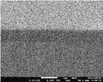
- 2 is a SEM photograph showing the surface of a filler-containing resin layer of Sample 1 obtained in Example 1.
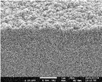
- 2 is a SEM photograph showing the surface of the filler-containing resin layer of Sample 2 obtained in Example 1.
- 4 is a SEM photograph showing the surface of a filler-containing resin layer of Comparative Sample 1 obtained in Comparative Example 1.
- the average particle diameter (D IA) is about 66 nm
- the coefficient of variation (CV) is a SEM photograph showing the secondary aggregation state of 45% of the insulating filler. It is a SEM photograph which shows the surface of the filler containing resin layer which employ
- the metal foil with a filler-containing resin layer according to the present invention is an electronic circuit for forming various electronic circuits having a laminated structure of a conductive layer and an insulating layer such as a capacitor circuit and a transistor circuit on a printed wiring board or a semiconductor substrate. It can be suitably used as a forming material or an electronic component forming material for forming various electronic components having a laminated structure of a conductive layer and an insulating layer such as a capacitor and a transistor.
- the manufacturing method of the metal foil with a filler content resin layer is explained.
- Metal foil with filler-containing resin layer The metal foil with filler-containing resin layer according to the present invention is obtained by laminating a metal foil and a filler-containing resin layer containing an insulating filler and a binder resin. First, the metal foil will be described.
- the metal foil according to the present invention is, for example, a layer used as a conductive layer, an electrode layer, or the like in the electronic circuit or electronic component.
- a metal foil obtained by a rolling method or an electrolytic method can be used.
- any metal foil such as copper foil, nickel foil, copper alloy foil (brass foil, corson alloy foil, etc.), nickel alloy foil (nickel-phosphorus alloy foil, nickel-cobalt alloy foil, etc.), etc. It may be used. However, from the viewpoint of satisfactorily forming a fine conductive pattern, a fine electrode pattern, or the like, considering that an electronic circuit is formed by etching or the like using the metal foil with a filler-containing resin layer.
- the metal foil is preferably made of copper or a copper alloy which has a lower electrical resistivity than nickel and is a nonmagnetic material. Further, copper is easily available compared to nickel and the like. Moreover, since copper foil is easy to process such as etching and is inexpensive, there is an advantage that adopting the copper foil as a metal foil is excellent in workability and can keep the manufacturing cost low. .
- the metal foil preferably has a smooth surface having a glossiness of more than 400 and a surface roughness (Ra) measured with an atomic force microscope of 10 nm or less in a measurement range of 5 ⁇ m ⁇ 5 ⁇ m. .
- Ra surface roughness
- the glossiness indicates a specular glossiness adopting Gs (60 °).
- the smooth surface of the metal foil as the subject is irradiated with measurement light at an incident angle of 60 °, and at a reflection angle of 60 °. It is a measure of the intensity of the bounced light.
- the glossiness was measured using a gloss meter VG-2000 manufactured by Nippon Denshoku Industries Co., Ltd. based on JIS Z 8741-1997.
- surface roughness points out the arithmetic mean value (Ra) measured with the atomic force microscope in the measurement range 5 micrometers x 5 micrometers as above-mentioned.
- the value obtained in the tapping mode using an atomic force microscope (Nanoscope V for Dimension series) manufactured by Nippon Bico Co., Ltd., and obtained under the condition of no flattening treatment. .
- the glossiness of the surface and the flatness of the metal foil there is a certain correlation between the glossiness of the surface and the flatness of the metal foil, and the flatness of the metal foil is often better as the glossiness is higher.
- the surface roughness (Ra) is 10 nm or less
- the glossiness is generally about 300 or more.
- the higher the glossiness the less the surface undulations and the more uniform the surface roughness. Therefore, the above-described effects can be obtained by using a metal foil having a smooth surface with glossiness and surface roughness (Ra) in the above range.
- glossiness or surface roughness shows a value outside the above range, the influence of the surface roughness of the metal foil appears on the surface of the filler-containing resin layer, which is not preferable.
- it is set as the structure which provides the ultra-thin filler containing resin layer as mentioned above on the said surface, the layer thickness of the said filler containing resin layer becomes non-uniform
- the filler-containing resin layer is laminated on the smooth surface of the metal foil.
- the filler-containing resin layer includes an insulating filler and a binder resin. Both the insulating filler and the binder resin are insulators, and the filler-containing resin layer is made of various insulating layers such as a gate insulating layer of a transistor circuit or a dielectric layer such as a capacitor circuit using its insulating characteristics or dielectric characteristics. It is a layer used as.
- the filler-containing resin layer on the smooth surface of the metal foil, as described above, due to the roughness of the surface of the metal foil, the thickness of the filler-containing resin layer becomes uneven or the filler-containing resin layer It is possible to prevent the surface of the resin layer from becoming rough.
- the filler-containing resin layer has a layer thickness of 0.1 ⁇ m to 3.0 ⁇ m.
- the layer thickness is as thin as 0.1 ⁇ m to 3.0 ⁇ m and the formation of fine wiring patterns and the like is good as described above, it contributes to the reduction of the thickness and size of various electronic circuits or various electronic components. it can.
- the filler-containing resin layer according to the present invention has a surface glossiness (Ra) when measured with an atomic force microscope in a measurement range of 5 ⁇ m ⁇ 5 ⁇ m with a surface glossiness greater than 200. It is characterized by being smaller than 25 nm. Since the surface smoothness is thus excellent, the generation of leakage current can be reduced, and a highly reliable electronic circuit or electronic component can be formed. Moreover, it can be judged that the excellent surface smoothness is that the insulating filler does not protrude unevenly on the surface of the filler-containing resin layer, and the insulating filler is uniformly dispersed in the layer. Therefore, it can be said that the filler-containing resin layer according to the present invention has a good dispersion of the insulating filler in the binder resin and has a homogeneous insulating characteristic or dielectric characteristic.
- the glossiness of the surface can be measured by the same method as the glossiness of the surface of the metal foil.
- the surface roughness can also be measured by the same method as the surface roughness of the metal foil.
- the relationship between the glossiness of the surface and the surface roughness is as described above. If the surface gloss is less than 200, the surface of the filler-containing resin layer may be locally rough even when the surface roughness (Ra) measured with an atomic force microscope is smaller than 25 nm. It may not be possible to obtain the effect.
- the surface roughness of the filler-containing resin layer is greater than 200, the surface roughness is uniform, and the surface gloss is uniform, the surface roughness (Ra ) Is larger than 25 nm, the surface roughness (Ra) itself does not reach the target range, and the target effect cannot be obtained.
- Binder resin Next, the binder resin will be described.
- a resin material used for forming an insulating base material of an electronic circuit material or an insulating layer of a printed wiring board can be suitably used.
- polyimide resin, epoxy resin, polyvinylidene fluoride, cyanoethyl pullulan, benzocyclobutene, polynorbornene, polytetrafluoroethylene, acrylate, or the like can be employed. Any one of these listed resins may be used, or a plurality of types of resins may be mixed and used.
- an epoxy resin and a polyimide resin can be used suitably among resin enumerated above as binder resin. This is because the epoxy resin and the polyimide resin are widely used as materials for forming the insulating layer, respectively, and the reliability of the insulating characteristics is high.
- an epoxy resin and a polyimide resin can use both suitably as binder resin, it is preferable to use a polyimide resin especially.
- the polyimide resin has higher heat resistance and higher insulation than the epoxy resin.
- the decomposition temperature of the epoxy resin is generally about 250 ° C.
- the decomposition temperature of the polyimide resin is about 450 ° C.
- the polyimide resin has high heat resistance to the epoxy resin.
- the volume resistivity of the epoxy resin is 1.0 ⁇ 10 14 ⁇ ⁇ cm and the dielectric breakdown voltage is about 40 kV / mm, whereas the volume resistivity of the polyimide resin is 1.5 ⁇ 10 16 ⁇ ⁇ cm.
- the dielectric breakdown voltage is 150 kV / mm, and the polyimide resin is superior in insulation compared to the epoxy resin. Therefore, by employing a polyimide resin, it is possible to obtain a filler-containing resin layer having higher heat resistance and excellent insulating properties.
- the insulating filler is dispersed and present in the filler-containing resin layer as an insulating layer, and is a component used for improving the insulating characteristics of the filler-containing resin layer or for improving the dielectric characteristics.
- inorganic oxide particles can be suitably used.
- inorganic oxide particles such as alumina particles, zirconia particles, and titanate particles can be selectively used.
- the perovskite-type dielectric particles include dielectric particles having a basic composition such as barium titanate, strontium titanate, barium strontium titanate, strontium zirconate, and bismuth zirconate.
- dielectric particles whose basic composition is any one of barium titanate, strontium titanate, and barium strontium titanate.
- the filler-containing resin layer can be used as a dielectric layer having a high relative dielectric constant by using dielectric particles having the composition as an insulating filler.
- the filler-containing resin layer can be suitably used as a dielectric layer of a capacitor circuit.
- the filler-containing resin layer can be suitably used as a dielectric layer of a capacitor circuit. it can.
- the average particle size (D IA ) of the insulating filler is preferably 5 nm to 150 nm, and more preferably 20 nm to 100 nm.
- the insulating filler fine particles having a very small particle diameter are employed, the particles form a certain secondary aggregation state. For this reason, the indirect measurement in which the average particle size is estimated from the measured values such as the laser diffraction scattering type particle size distribution measurement method cannot accurately measure the particle size of the insulating filler. Therefore, in the present invention, the insulating filler is directly observed with a scanning electron microscope (SEM), and the average particle size of secondary particles obtained by image analysis of the SEM image is used as an index.
- SEM scanning electron microscope
- the insulating filler fine particles having the average particle diameter (D IA ) in the range of 5 nm to 150 nm, the insulating filler is crushed when preparing the coating liquid, and the coating liquid is excellent in the coating liquid. Can be dispersed. Therefore, the insulating filler can be uniformly dispersed in the state of fine primary particles in the ultra-thin filler-containing resin layer of 0.1 ⁇ m to 3 ⁇ m, and the surface glossiness and surface roughness within the above ranges can be achieved. Can do.
- D IA average particle diameter
- the insulating filler can be uniformly dispersed in such an extremely thin filler-containing resin layer, an insulating layer or dielectric layer having uniform insulating characteristics or dielectric characteristics and having no surface variation is formed. Can do.
- insulating filler fine particles having a particle size within the above range it is possible to increase the filling ratio of the insulating filler in the filler-containing resin layer while maintaining the smoothness of the surface, and to have high insulation characteristics.
- a layer can be formed.
- the average particle diameter (D IA ) of the insulating filler refers to that obtained by image analysis of the SEM image, and specifically refers to the value obtained by the following procedure.
- a sample (insulating filler) was photographed at a magnification of 200,000 to obtain an SEM photograph.
- the photographing target position of the sample was an arbitrary position.
- the sample position was changed, and the sample was shot a plurality of times to obtain a plurality of SEM photographs having different shooting target positions.
- one of the plurality of SEM photographs was selected so that the insulating filler particles overlap little and the insulating filler particles in an aggregated state can be easily identified (see FIG. 1).
- the outline of each insulating filler particle is circled, and the major axis is It measured as a particle size (secondary particle size) of insulating filler particles.
- the average value of the particle diameters of the insulating filler particles thus measured was defined as the above average particle diameter ( DIA ).
- the average particle diameter (D IA ) can also be obtained by image processing.
- image processing for example, using an IP-1000PC manufactured by Asahi Engineering Co., Ltd., circular particle diffraction with a circularity threshold of 10 and an overlap of 20 is performed on the SEM image acquired in the same procedure as described above.
- the average particle diameter (D IA ) can also be obtained.
- Variation in particle size In the present invention, from the viewpoint of forming a flatter filler-containing resin layer with excellent surface gloss, it is better that the variation in the particle size of the insulating filler is small.
- the variation in the particle size of the insulating filler is small.
- CV coefficient of variation
- the insulating filler By using an insulating filler having a sharp particle size distribution with a coefficient of variation (CV) represented by the above formula of 40% or less, the insulating filler is well dispersed in the coating solution. As a result, the filling rate of the insulating filler in the filler-containing resin layer can be improved, and the smoothness of the surface of the filler-containing resin layer can be further improved.
- CV coefficient of variation
- Filling rate of insulating filler In the filler-containing resin layer, when the total amount of the insulating filler and the binder resin is 100 wt%, the insulating filler is preferably contained in an amount of 50 wt% to 90 wt%. In the filler-containing resin layer, when the total amount of the insulating filler and the binder resin is 100 wt%, by containing the insulating filler in an amount of 50 wt% to 90 wt%, the filling rate of the insulating filler is high, and the insulating characteristics or dielectric characteristics A high layer can be obtained.
- the content of the insulating filler is less than 50 wt%, even when the thickness of the filler-containing resin layer is increased, the filling rate of the insulating filler is low, and a dielectric characteristic at a level required in the market can be obtained. It becomes difficult. Moreover, when the content rate of an insulating filler exceeds 90 wt%, since the content rate of binder resin will be less than 10 wt% and the adhesiveness of an insulating filler resin layer and metal foil will be impaired, it is unpreferable.
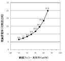
- FIG. 2 shows the theoretical dielectric constant with respect to the content (filling rate) of the insulating filler when the sum of the amount of the insulating filler and the binder resin is 100 wt%.
- FIG. 2 shows the theoretical dielectric constant based on the logarithmic mixing rule of the filler-containing resin layer when BaTiO 3 is used as the insulating filler and polyimide is used as the binder resin component.
- the relative dielectric constant of polyimide is 3.2
- the relative dielectric constant of BaTiO 3 is 100.
- the specific gravity of the polyimide is 1.43 g / cm 3
- the specific gravity of the BaTiO 3 is 5.5 g / cm 3.
- the theoretical dielectric constant of the filler-containing resin layer based on the logarithmic mixing rule is 6.5. Further, when the content of the insulating filler is 90 wt%, the theoretical dielectric constant is 35.7.
- the relative dielectric constant of BaTiO 3 that is a ferroelectric is extremely high as compared with polyimide that is a binder resin component.
- the theoretical dielectric constant of the filler-containing resin layer also increases. In particular, when the content of the insulating filler exceeds 70 wt%, the theoretical dielectric constant of the filler-containing resin layer becomes 11.7.
- the higher the content of the insulating filler the more preferable, for example, the content of the insulating filler is preferably 70 wt% or more. .
- the method for producing a metal foil with a filler-containing resin layer according to the present invention is a method for producing the above-described metal foil with a filler-containing resin layer according to the present invention. It has a coating process, a 2-3 drying process, and a 2-4 heat treatment process. Hereinafter, each step will be described.
- the coating solution preparation step according to the present invention is a step of preparing a coating solution in which an insulating filler is dispersed in a varnish containing a binder resin component and a solvent. First, after describing the varnish and the coating liquid, the viscosity of the coating liquid, the concentration of each coating liquid component, and the like will be described.
- varnish the solution containing the binder resin component and the solvent before the insulating filler is added.
- Binder resin component refers to a precursor of the binder resin.
- the precursor of the binder resin refers to, for example, a monomer, oligomer, prepolymer before condensation polymerization or before cross-linking that constitutes the target binder resin by condensation polymerization or cross-linking reaction.
- components such as a polymerization initiator, a crosslinking agent, a hardening
- a polyimide resin is employed as the binder resin
- a polyamic acid that is a polyimide precursor can be employed as the binder resin component.
- the binder resin component includes an epoxy resin before crosslinking, a crosslinking agent, a curing agent, and the like.
- solvent an organic solvent capable of dissolving the binder resin component is selected.
- a highly volatile organic solvent it is preferable to use a highly volatile organic solvent.
- an appropriate solvent as appropriate depending on the type of the binder resin component.
- a solvent capable of dissolving polyamic acid which is a precursor of polyimide resin or biphenyltetracarboxylic dianhydride and paraphenylenediamine which are monomers for obtaining polyamic acid Is selected.
- N-methyl-2-pyrrolidone can be employed as the solvent.
- the binder resin for example, methyl ethyl ketone or cyclopentanone and a mixed solvent thereof can be used as the solvent.
- the present invention is not limited to these solvents, and other solvents can be used as appropriate as long as they can dissolve the binder resin component and have high volatility.
- the above varnish may be prepared by mixing a solvent and a binder resin by itself, or a commercially available varnish containing the above components at a predetermined concentration may be used. Moreover, when using a commercially available varnish, it can also dilute suitably with a solvent and can be used after preparing to a preferable density
- the coating liquid which concerns on this invention is prepared by adding an insulating filler to the varnish prepared as mentioned above, and disperse
- a dispersant made of a surfactant or the like may be added as appropriate.
- an insulating filler having an average particle diameter (D IA ) of secondary particles in an aggregated state of 5 nm to 150 nm can be used, and an average particle diameter (D IA ) of 20 nm to 100 nm can be used. It is more preferable to use an insulating filler. In addition, it is preferable to use an insulating filler having a variation coefficient (CV) of 40% or less.
- CV variation coefficient
- the concentration of various components when preparing the coating solution will be described.
- concentration of each component in a coating liquid is adjusted so that the viscosity of a coating liquid may be 300 mPa * s or less.
- the viscosity of the coating solution can be maintained, and the coating solution can be uniformly applied to the smooth surface of the metal foil to form a coating film with a flat surface. This is because it can be done.
- the glossiness and surface roughness of the surface of the filler-containing resin layer obtained through the drying step and the heat treatment step can be in the above ranges.
- the viscosity is a value measured by a tuning fork type vibration measuring method at 25 ° C. ⁇ 5 ° C. The viscosity can be measured using, for example, a tuning fork type vibration viscometer SV-10 manufactured by A & D Co., Ltd.
- the blending ratio of the insulating filler and the binder resin component is determined so as to include 50 wt% to 90 wt% of the insulating filler.
- resin solid content refers to the weight of the binder resin finally obtained using the binder resin component contained in the varnish.
- the filling rate of the insulating filler in the finally obtained filler-containing resin layer can be within the above-described preferable range.
- the addition amount of an insulating filler is determined according to the binder resin concentration in a varnish.
- Binder resin concentration in varnish The viscosity of the coating solution varies depending on the binder resin concentration in the varnish.
- the binder resin concentration refers to the binder resin concentration when the amount of the binder resin finally obtained is converted using the binder resin component contained in the varnish. That is, the binder resin concentration here refers to a so-called resin solid content concentration.
- the concentration of the binder resin in the varnish is determined in consideration of adjusting the viscosity of the coating solution to 300 mPa ⁇ s or less, preferably 100 mPa ⁇ s or less.
- the lower the binder resin concentration (resin solid content concentration) in the varnish the lower the viscosity of the coating solution.
- the binder resin concentration in the varnish is low.
- the binder resin concentration in the varnish is low, the amount of solvent to be volatilized (the amount of volatile components) in the drying process increases, so that fine pores (voids) are generated in the film when the coating film is dried, The volume shrinkage of the coating film increases.
- the surface of the coating film becomes rough in the drying step, and the risk of roughening the surface of the finally obtained filler-containing resin layer increases. Therefore, from the viewpoint of suppressing the generation of voids in the coating film and suppressing the volume shrinkage of the coating film during drying, the binder resin concentration in the varnish can be adjusted in consideration of the viscosity of the coating liquid.
- the binder resin concentration so that the viscosity of the coating solution is 300 mPa ⁇ s or less, but the viscosity of the varnish itself may exceed 300 mPa ⁇ s.
- the total solid content concentration of the insulating filler and the binder resin amount obtained from the above binder resin component in the coating solution is It is preferable that the viscosity be as high as possible within a range in which the viscosity is maintained at 300 mPa ⁇ s or less, preferably 100 mPa ⁇ s or less.
- the amount of the solvent, which is a volatile component is reduced, and the formation of voids in the coating film during the process of volatilization of the solvent in the drying process is prevented. This is because it is possible to form a filler-containing resin layer that is uniform and has a smooth surface.
- FIG. 3A shows the viscosity of the coating liquid before dispersing the insulating filler
- FIG. 3B shows the viscosity of the coating liquid after dispersing the insulating filler.
- the insulating filler 3 employs a polyimide resin as a binder resin and N-methyl-2-pyrrolidone as a solvent.
- the insulating filler employs BST particles having an average particle diameter (D IA ) of about 68 nm, and no dispersant is added. Further, the insulating filler is dispersed for 1 hour using a micro media having a bead diameter of 0.3 mm made of zirconia by a picomil disperser (wet pulverizing / dispersing machine), and then the bead diameter of 0.1 mm is also made of zirconia It was dispersed for 1 hour using fine media.
- D IA average particle diameter
- the viscosity of the coating liquid is reduced by dispersing the insulating filler even when the solid concentration in the coating liquid is the same. Therefore, as described above, even when the viscosity of the varnish exceeds 300 mPa ⁇ s, the viscosity of the coating liquid can be reduced to 300 mPa ⁇ s or less by appropriately dispersing the insulating filler. Therefore, it is preferable to determine the solid content concentration in the coating liquid in consideration of the fact that the viscosity of the coating liquid can be reduced as the insulating filler is dispersed.
- Insulating filler concentration in the coating solution is preferably as high as possible after keeping the viscosity of the coating solution within the above range.
- Dispersion characteristics of insulating filler are shown in FIG. 4A and 4B show changes in the viscosity of the coating solution with respect to the dispersion time, respectively.
- FIG. 4A shows the change in the viscosity of the coating liquid when a polyimide resin is used as the binder resin
- FIG. 4B shows the change in the viscosity of the coating liquid when an epoxy resin is used as the binder resin. Show.
- the coating liquid shown in FIG. 4 (a) is prepared without adding a dispersant
- the coating liquid shown in FIG. 4 (b) is prepared by adding a dispersant.
- the viscosity of the coating solution is reduced by appropriately dispersing the insulating filler, regardless of which of the polyimide resin and the epoxy resin is used as the binder resin. I understand that. However, when FIGS. 4A and 4B are compared, the degree of decrease in the viscosity of the coating liquid accompanying the dispersion of the insulating filler is greater when the epoxy resin is used than when the polyimide resin is used. I understand.
- the binder resin concentration in the varnish, the solid content concentration in the coating solution, and the insulating filler concentration it is preferable to adjust the binder resin concentration in the varnish, the solid content concentration in the coating solution, and the insulating filler concentration to appropriate concentrations according to the type of resin employed as the binder resin.
- an appropriate dispersant it is preferable to add the dispersant as appropriate.
- an epoxy resin for example, BYK-111 manufactured by Big Chemie can be used as a dispersant.
- this dispersant By blending this dispersant with about 2 mg per 1 m 2 of the surface area of the insulating filler, significant effects can be obtained with respect to the dispersion state of the insulating filler and the decrease in the viscosity of the coating solution. Therefore, by using an appropriate dispersant, the viscosity of the coating solution can be adjusted within the above range, and the binder resin concentration in the varnish can be increased as compared with the case where no dispersant is used, and The solid content concentration and the insulating filler concentration in the coating liquid can be increased.
- a binder resin that can keep the viscosity of the coating solution low due to the viscosity of the resin or the presence of a dispersant even when the solid content concentration is relatively high
- a resin a preferable range of the solid content concentration and the insulating filler concentration in the coating liquid and a preferable range of the binder resin concentration in the varnish are exemplified.
- a preferable range of each concentration is exemplified by taking a polyimide resin as an example.
- the polyimide resin will be described.
- the total solid concentration in the coating solution is preferably 20.5 wt% to 55.5 wt%, more preferably 20.5 wt% to 33.1 wt%.
- the concentration of the insulating filler in the coating solution is preferably 14.4 wt% to 44.4 wt%, and more preferably 14.4 wt% to 26.5 wt%.
- the binder resin concentration in the varnish is preferably 7.2 wt% to 20 wt%, and more preferably 7.2 wt% to 9 wt%.
- the viscosity of the coating solution can be adjusted to be 300 mPa ⁇ s or less. Further, by adjusting the dispersion time as shown in FIGS. 3 (a) and 4 (a), the viscosity of the coating solution can be lowered to 100 mPa ⁇ s or less. Moreover, by adjusting within the range, a filler-containing resin layer having a uniform thickness and a smooth surface can be formed. Further, by adjusting the concentration of each component to a more preferable range, a filler-containing resin layer having a more uniform thickness and a smoother surface can be formed with good reproducibility. In addition, variations in the insulating properties and dielectric properties of the finally obtained filler-containing resin layer can be prevented.
- the total solid content concentration and the insulating filler concentration in the coating liquid and the binder resin concentration in the varnish can be made higher than the above-described ranges.
- Epoxy resin When an epoxy resin is used as the binder resin, the total solid concentration in the coating solution is preferably 60 wt% to 90 wt%, and more preferably 70 wt% to 80 wt%.
- the concentration of the insulating filler in the coating solution is preferably 48 wt% to 72 wt%, and more preferably 56 wt% to 64 wt%.
- the binder resin concentration in the varnish is preferably 10.3 wt% to 15.4 wt%, and more preferably 12.0 wt% to 13.7 wt%.
- the dispersant is blended in the coating liquid at a ratio of 1.7 wt% to 2.3 wt%. This is because, as shown in FIG. 4B, the viscosity of the coating solution can be remarkably reduced by adding a dispersant. For this reason, compared with a polyimide resin, the total solid content concentration and the insulating filler concentration in the coating liquid can be increased, and the binder resin concentration in the varnish can be increased. That is, even when the total solid content concentration of the coating solution is increased, it is relatively easy to adjust the viscosity of the coating solution to 300 mPa ⁇ s or less. It is easier to form a filler-containing resin layer having a smooth surface than when a resin is employed.
- the binder resin polyimide resin and epoxy resin are taken as examples, and the preferred ranges of the respective concentrations are specifically exemplified and described.
- the binder resin according to the present invention includes these resins.
- the above-described various resins can be applied without limiting the purpose. When using other resins, considering the kind of binder resin, the presence or absence of an appropriate dispersant, the dispersion characteristics of the insulating filler with respect to the varnish, etc. It is preferable to prepare a liquid.
- Dispersion time Next, the dispersion time of the insulating filler will be described. As described above, by dispersing the insulating filler, the viscosity of the coating solution is lower than the viscosity of the varnish. As shown in FIG. 4, the dispersion time is preferably 20 minutes or more from the viewpoint of reducing the viscosity of the coating solution. This is because, by setting the dispersion time of the insulating filler to 20 minutes or more, the viscosity of the coating liquid after dispersion can be remarkably reduced as compared with the viscosity of the coating liquid before dispersion.
- the dispersion time of the insulating filler is longer even when the dispersion time is longer and when the dispersion time is shorter, even if the viscosity of the coating liquid is not greatly different.
- the dispersion time of the insulating filler is increased, the insulating filler in the aggregated state is crushed and dispersed more uniformly in the solvent in a finer state, so that the glossiness of the surface is higher and the surface is flat. This is because a filler-containing resin layer can be formed.
- the time required to improve the dispersion state of the insulating filler varies depending on the particle size of the insulating filler, the wettability of the insulating filler to the solvent, the type of resin used as the binder resin, and the like. For this reason, the preferable range of dispersion
- the smaller the particle size of the insulating filler to be employed the longer the dispersion time, and the lower the degree of decrease in the viscosity of the coating solution accompanying the dispersion, the longer the dispersion time.
- the degree of decrease in the viscosity of the coating liquid accompanying dispersion is lower in the polyimide resin than in the epoxy resin. Therefore, when the polyimide resin is employed as the binder resin, the dispersion state of the insulating filler can be improved by taking a longer dispersion time of the insulating filler.
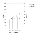
- FIG. 5 shows a graph showing the relationship between the viscosity of the coating solution according to the dispersion time of the insulating filler and the glossiness of the surface of the finally obtained filler-containing resin layer.
- the coating liquid shown in FIG. 5 is the same as the coating liquid shown in FIG.
- the dispersion time of the insulating filler is increased, the glossiness of the surface of the finally obtained filler-containing resin layer is improved, and a filler-containing resin layer having a smoother surface can be formed. I understand that.
- the viscosity of the coating liquid having a dispersion time of 60 minutes is lower in the coating liquid having a dispersion time of 60 minutes and the coating liquid having a dispersion time of 80 minutes.
- the glossiness of the surface of the filler-containing resin layer formed using the coating solution having a dispersion time of 60 minutes is lower than the glossiness of the surface of the filler-containing resin layer formed using the coating solution having a dispersion time of 80 minutes.
- the insulating filler in the aggregated state is sufficiently crushed, and the insulating filler is uniformly in the solvent in the form of primary particles.
- a filler-containing resin layer having a smoother surface can be formed.
- the inorganic oxide particles having the above-mentioned particle size range are used as the insulating filler, considering the results shown in FIG. 5, a polyimide resin is used as the binder resin, and the average particle size (D IA ) is about 68 nm.
- the time for dispersing the insulating filler is preferably 60 minutes or more from the viewpoint of forming a smooth filler-containing resin layer having a surface glossiness of 200 or more. 80 minutes or more is more preferable.
- Disperser When dispersing the insulating filler, various dispersers such as a media disperser, a high-speed shear disperser, and a high-pressure disperser can be used.
- the media disperser for example, the above-mentioned Picomill: PCM-LR manufactured by Asada Tekko Co., Ltd. can be used.
- Super Aspec Mill manufactured by Kotobuki Industries Co., Ltd., Bead Mill manufactured by Ashizawa Finetech Co., Ltd .: Star Mill Nano Getter, etc. can be used.
- the dispersion medium it is preferable to use a minute medium having a bead diameter of 0.3 mm to 0.03 mm from the viewpoint of improving the dispersion of the insulating filler.
- the reason for using minute media is as follows. As described above, the dispersion time of the insulating filler is preferably long. However, simply increasing the dispersion time of the insulating filler causes a problem of “overdispersion” such as a decrease in crystallinity and re-aggregation of the insulating filler.
- the energy given to the insulating filler particles at a time is reduced, thereby preventing overdispersion of the insulating filler.
- the insulating filler can be more favorably dispersed in the solvent while preventing the overdispersion of the insulating filler.
- a high-speed shearing machine for example, TK Filmics manufactured by PRIMIX Corporation can be used.
- the high-pressure disperser a nanomizer manufactured by Yoshida Kikai Kogyo Co., Ltd. can be used. Even when media is not used, by using these high-speed shearing machines and high-pressure dispersers, it is possible to prevent overdispersion, and in the image of “unraveling” the insulating filler in the secondary aggregation state, The insulating filler can be favorably dispersed in the solvent in the form of primary particles while gradually pulverizing from the surroundings.
- a coating process is a process of apply
- Metal foil The metal foil used in the process has a smooth surface with a surface glossiness greater than 400 and a surface roughness (Ra) measured with an atomic force microscope in a measurement range of 5 ⁇ m ⁇ 5 ⁇ m of 10 nm or less. It is characterized by that.
- Ra surface roughness
- Application method When applying the application liquid onto the smooth surface of the metal foil, a conventionally known method can be employed. For example, using a gravure coater, reverse gravure coater, reverse kiss gravure coater, die coater, bar coater, comma coater, blade coater, lip coater, rod coater, squeeze coater, reverse roll coater, transfer roll coater, etc. It can be applied to a smooth surface.
- a kiss gravure coater is preferably used.
- the drying step is a step of drying the coating film formed on the smooth surface of the metal foil after the completion of the coating step to volatilize and remove the volatile component (solvent) in the coating film.
- the resin solid content concentration is increased as much as possible, and the speed at which the volatile components in the coating film are removed in the drying process (hereinafter referred to as “the following”)
- the above-mentioned filler-containing resin layer having a smooth surface according to the present invention can be obtained with good reproducibility and yield by controlling the “drying speed” as follows.
- the present invention in the drying step, it is characterized in that to volatilize the volatile components in the coating film at a rate of 0.001mg / min ⁇ cm 2 ⁇ 0.250mg / min ⁇ cm 2. That is, it is preferable to control the drying conditions so that the volatile components in the coating film are volatilized at a rate of 0.001 mg / min to 2 mg / min per 1 cm 2 of the metal foil. Further, in the drying step, it is preferable to keep the drying rate constant and to volatilize the volatile components in the coating film slowly at the above ratio. In the process of drying the coating film, the coating liquid self-flows by gravity so that its thickness becomes horizontal.
- the filler since the viscosity of the coating solution is high, the flow is slow, and it takes time until the surface of the coating film becomes horizontal. That is, so-called leveling time is required. Therefore, in the present invention, the filler has a uniform coating film thickness and a smooth surface by slowly volatilizing the solvent while ensuring the leveling time so as not to prevent the self-flow of the coating liquid. It is possible to form the containing resin layer. Depending on the volatility of the solvent and the viscosity of the coating solution, it is preferable to set the drying rate to an appropriate value as appropriate. However, as a result of diligent research by the present inventors, the coating film is used under such drying conditions that the drying rate is in the above range.
- the glossiness and surface roughness of the surface of the filler-containing resin layer obtained through the heat treatment step described below are in the above-mentioned range.
- the concentration of the insulating filler in the coating liquid is increased, simply drying does not provide sufficient leveling time, and the present invention is concerned.
- a filler-containing resin layer cannot be obtained. Based on the diligent research of the present inventors, it has become possible to obtain an extremely smooth filler-containing resin layer with good reproducibility by drying the coating film at the drying speed.
- the upper limit of the drying rate is more preferably 1 mg / min ⁇ cm 2 or less.
- the drying speed refers to the speed determined as follows. First, a sufficient amount of coating solution is poured into a container having a flat bottom surface. The coating liquid weight at this time is measured together with the container weight. Next, the weight of the coating solution at the time when a predetermined time has elapsed since the start of drying in the sealed space is measured together with the container weight. Then, based on the difference in the weight of the coating solution in the container before and after the start of drying, the amount of solvent volatilized until a predetermined time has elapsed is obtained. And the said drying speed is calculated
- the drying speed was determined with the predetermined time being 10 minutes.
- the drying conditions refer to drying temperature, atmospheric humidity, atmospheric pressure, and the like.
- the drying speed was calculated for each drying condition while changing the drying conditions, and the correlation between the drying conditions and the drying speed was obtained in advance.
- the coating film was dried under the drying conditions satisfying the drying speed in the above range based on the relationship between the drying speed and the drying conditions thus obtained.
- the drying rate of the coating solution is less than 0.001 mg / min ⁇ cm 2 , the volatilization of the coating solution is slow, which is not commensurate with the industrial production efficiency. Further, when the drying rate of the coating solution is less than 0.001 mg / min ⁇ cm 2 , the coating film may absorb moisture depending on the atmospheric humidity. When the coating film absorbs moisture, moisture absorbed at the time of drying evaporates, and the surface of the coating film tends to be uneven, and the filler-containing resin layer having the surface glossiness and surface roughness (Ra) in the above-mentioned range. It becomes difficult to form.
- Atmospheric humidity As described above, when the coating film absorbs moisture, the drying rate deviates from the above range, and the filler-containing resin layer having a smooth surface having surface glossiness and surface roughness (Ra) within the above range. It becomes difficult to form. Therefore, in the drying step, it is preferable to dry the coating film so as to satisfy the above-described drying speed in a state where moisture absorption of the coating film is prevented. Moreover, when the coating film weight increases due to moisture absorption before the drying process starts, it becomes difficult to form a filler-containing resin layer having a smooth surface for the same reason as described above.
- the increase in the coating film weight after the coating film is formed is 5% or less of the solvent weight used for the preparation of the coating liquid. It is preferable that it is 4% or less. Of course, it is most preferable to avoid moisture absorption of the coating film. Therefore, before the drying process is started, it is preferable to store the coating film in a conditioned atmosphere having a relative humidity of 25% or less, for example, in order to prevent moisture absorption of the coating film. Moisture absorption of the coating film is not observed in an atmosphere having a relative humidity of 20% or less. On the other hand, if the relative humidity exceeds 25%, moisture absorption of the coating film may be observed depending on the atmospheric temperature and the atmospheric humidity.
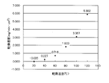
- Drying temperature Here, for reference, the coating film is shown in FIG. 6 in a sealed space in which the humidity is adjusted so that the relative humidity when converted to 20 ° C. is 30% (absolute humidity 0.0055 kg / kg). The relationship between the drying temperature and drying speed when drying is shown. As shown in FIG. 6, when the drying temperature was 20 ° C. in the humidity control atmosphere, the drying rate per unit area was ⁇ 0.035 mg / min ⁇ cm 2 . That is, an increase in the coating film weight was observed. It was confirmed that when the coating film was dried at a high drying temperature in the humidity-controlled atmosphere, the drying rate per unit area was naturally increased as the drying temperature was increased.
- the drying rate was 0.227 mg / min ⁇ cm 2 .
- the relative humidity at this time is calculated to be 9.5%.
- the drying temperature was 60 ° C.
- the drying rate was 0.716 mg / min ⁇ cm 2 .
- the relative humidity at this time is 3.5% when calculated.
- the finally obtained filler-containing resin layer had the same surface glossiness and surface roughness.
- the surface gloss of the finally obtained filler-containing resin layer is greater than 200 and measured with an atomic force microscope in a measurement range of 5 ⁇ m ⁇ 5 ⁇ m.
- a roughness (Ra) of less than 25 nm was obtained.
- the glossiness of the surface was low and the surface roughness became rough as compared with those obtained by drying the coating film at a drying temperature of 40 ° C or 60 ° C.
- the upper limit of the drying rate is 1 mg / min ⁇ from the viewpoint that a filler-containing resin layer having excellent surface gloss and small surface roughness can be formed with good reproducibility. it is more preferable that the cm 2 or less.
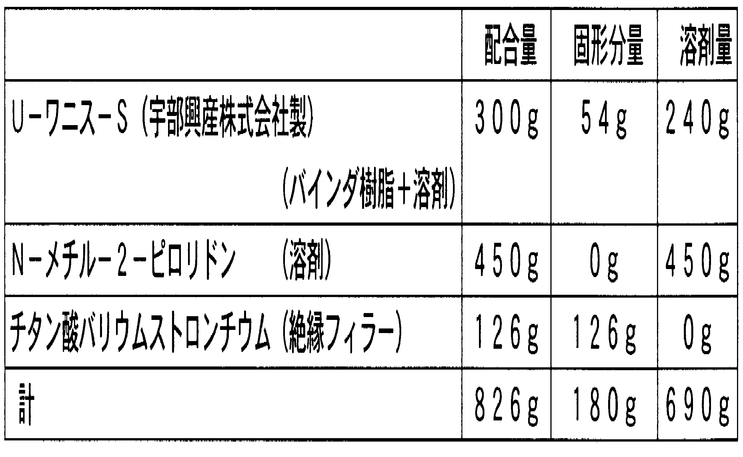
- Coating solution preparation step In this example, a coating solution was prepared using a commercially available varnish. Table 1 shows the amount of each coating solution component used in preparing the coating solution. In this example, since a commercially available varnish was used in the preparation of the coating solution, the resin solid content concentration was adjusted and the viscosity was adjusted separately using a solvent in order to prepare the resin solid content concentration in the varnish. .
- Binder resin In this example, polyimide resin was used as the binder resin. As shown in Table 1, 300 g of U-varnish-S manufactured by Ube Industries, Ltd. was used as the varnish.
- the varnish is a 20 wt% polyamic acid solution in which polyamic acid, which is a precursor of polyimide resin, is dissolved in N-methyl-2-pyrrolidone. Polyamic acid can be obtained using tetracarboxylic dianhydride and diamine as raw materials.
- the polyamic acid solution employs a solution obtained from biphenyltetracarboxylic dianhydride and paraphenylenediamine.
- the polyamic acid By heat-treating the polyamic acid, a dehydration reaction occurs, and the polyamic acid is polycondensed to become a polyimide resin.
- the weight of the obtained polyimide resin is reduced by 10 wt% with respect to the weight of the polyamic acid. Therefore, the resin solid content concentration in the varnish is 18 wt%.
- the resin solid content contained in 300 g of the varnish is 54 g, and the amount of solvent is 240 g.
- Solvent In this example, the same N-methyl-2-pyrrolidone as the solvent contained in the varnish was used as the solvent. As described above, the varnish contains about 240 g of N-methyl-2-pyrrolidone. Therefore, 690 g of solvent was used in the entire coating solution.
- Insulating filler In this example, 126 g of barium strontium titanate powder was used as the insulating filler. In the barium strontium titanate, the ratio of barium to strontium is 9. The density of the powder was 5.5 g / cm 3 , and the average secondary particle diameter (D IA ) of the insulating filler was about 68 nm. However, the average secondary particle diameter (D IA ) is a value obtained based on the SEM photograph as described above. An SEM photograph showing the insulating filler is shown in FIG.
- a varnish having a resin solid content concentration of 7.2 wt% was diluted with 450 g of the solvent using the above-described coating solution components to prepare a varnish having a resin solid content concentration of 7.2 wt%.
- 126 g of the barium titanate was added to the varnish, and dispersed for 80 minutes using a fine media having a bead diameter of 0.05 mm using a picomill disperser to prepare a coating solution in this example.
- the weight concentration of the insulating filler in the coating solution is 15.3 wt%. Further, the weight concentration of the total solid content of the insulating filler and the binder resin (resin solid content) in the coating solution is 21.8 wt%.
- the blending amount of each component of the coating liquid is adjusted so that the insulating filler is contained at 70 wt% when the total weight of the insulating filler and the resin solid content in the final filler-containing resin layer obtained by heat treatment is 100 wt%. It has been done.
- Coating step In the coating step, two copper foils having a surface area of 10 cm 2 and a layer thickness of 18 ⁇ m were used, and the coating solution was applied to the smooth surface of the copper foil using a bar coater. At this time, the coating solution was applied to the smooth surface of the copper foil so that the finally obtained filler-containing resin layer had a thickness of 1 ⁇ m. However, the glossiness of the smooth surface of the copper foil was 538, and the surface roughness (Ra) was 5.7 nm.
- Drying step After the coating step, the coating film was dried to form a semi-cured filler-containing resin layer on the smooth surface of the metal foil. In the drying step, the coating film was dried by changing the drying conditions of the two coated film-coated copper foils prepared in the coating step.
- Sample 1 Of the two copper foils with a coating film, one copper foil with a coating film was dried so that the drying rate per unit area was 0.227 mg / min ⁇ cm 2 .
- the actual drying conditions at this time were a drying temperature of 40 ° C. and a normal pressure. The relative humidity at this time was 12%. Under the drying conditions, the coating film was dried for 60 minutes. However, actually, the coating film was dried in about 30 minutes.
- a copper foil with a filler-containing resin layer obtained under the drying conditions is designated as Sample 1.
- Sample 2 The other coated film-coated copper foil was dried so that the drying rate per unit area was 0.002 mg / min ⁇ cm 2 .
- the actual drying conditions at this time were a drying temperature of 25 ° C., a nitrogen substitution atmosphere, and normal pressure. At this time, drying of the coating film took 5 days.
- Sample 2 is a copper foil with a filler-containing resin layer obtained under the drying conditions.
- Comparative Sample 1 was produced in the same manner as Sample 1, except that the drying rate per unit area was 5.882 mg / min ⁇ cm 2 .
- the actual drying conditions at this time were a drying temperature of 120 ° C. and normal pressure.
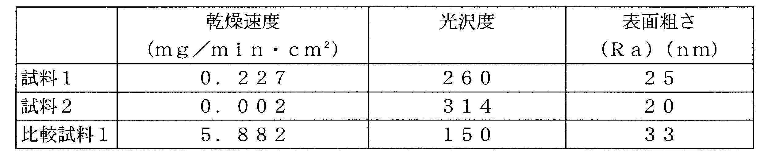
- the glossiness is a value measured using a gloss meter VG-2000 manufactured by Nippon Denshoku Industries Co., Ltd. based on JIS Z 8741-1997. Further, the surface roughness was measured in a tapping mode using an atomic force microscope: Nanoscope V for Dimension series manufactured by Nippon Bico Co., Ltd., and was a value obtained under the condition that no flattening treatment was performed. The results are shown in Table 2.
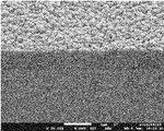
- Comparative Sample 1 had a glossiness of 150 on the surface, and the surface was rougher than Samples 1 and 2 as shown in FIG.
- the surface roughness (Ra) was about 25 nm and 20 nm for Sample 1 and Sample 2, respectively, whereas it was about 33 nm for Comparative Sample 1.
- the filler-containing resin layer finally obtained by changing the dispersion time at the time of preparing the coating liquid, even if the blending amounts of various components contained in the coating liquid are the same.
- the surface gloss is different.
- the smoothness of the surface of the filler-containing resin layer finally obtained can be made constant by strictly controlling the dispersion time of the coating liquid and the drying conditions of the coating film. Was confirmed.
- a filler-containing resin having a glossiness of 200 or more and a surface roughness (Ra) measured by an atomic force microscope of less than 25 nm in a measurement range of 5 ⁇ m ⁇ 5 ⁇ m by adjusting dispersion conditions and drying conditions. I'm getting a layer.
- the filler-containing resin layer is produced in a large area easily and with good reproducibility. be able to.
- a reference sample was prepared in the same manner as Sample 1 of Example 1 except that an insulating filler having an average particle diameter (D IA ) of about 66 nm and a coefficient of variation (CV) of 45% shown in FIG. 10 was used. Although there was no significant difference in the viscosity at the time of preparing the coating solution, the glossiness of the surface of the finally obtained filler-containing resin layer was compared with Sample 1 having a coefficient of variation (CV) of 38%.
- the reference sample using the insulating filler having a coefficient of variation (CV) of 45% was lower by about 20% than the sample 1. From this, it can be determined that a filler-containing resin layer having a smoother surface can be obtained with good reproducibility by using an insulating filler having a lower coefficient of variation (CV), that is, a smaller variation in particle size.
- FIG. 11 shows a surface photograph of a filler-containing resin layer produced by using an epoxy resin as a binder resin.
- the SEM photograph was taken in the same manner as Sample 1 and the like.
- an insulating filler is added to a varnish having a binder resin concentration of 13.7 wt%, and a dispersant (BYK-111; manufactured by BYK Chemie) is added at a concentration of 2.3 wt%.
- the coating solution was prepared so that the concentration of the insulating filler in the coating solution was 65 wt% and the total solid concentration in the coating solution was 80 wt%.
- the viscosity of the coating solution at this time was 63.6 mPa ⁇ s.
- the viscosity of the coating solution prepared in Example 1 was 95.8 mPa ⁇ s.
- the viscosity of the coating solution can be greatly reduced by adding a dispersant. Therefore, compared with the case where a polyimide resin is used as the binder resin, the total solid content concentration in the coating solution can be increased. Therefore, the epoxy resin can form a filler-containing resin layer having a smooth surface with good reproducibility and relatively easily as compared with the polyimide resin.
- the metal foil with a filler-containing resin layer according to the present invention is an electronic circuit forming material for forming various electronic circuits on a printed wiring board or a semiconductor substrate, or an electronic component forming material for forming various electronic components. It can be preferably used.
- the filler-containing resin layer is a thin film and has excellent surface smoothness, a highly reliable electronic circuit or electronic component can be formed.
Landscapes
- Engineering & Computer Science (AREA)
- Microelectronics & Electronic Packaging (AREA)
- Manufacturing & Machinery (AREA)
- Laminated Bodies (AREA)
- Structures Or Materials For Encapsulating Or Coating Semiconductor Devices Or Solid State Devices (AREA)
- Application Of Or Painting With Fluid Materials (AREA)
Abstract
Description
本件発明に係るフィラー含有樹脂層付金属箔は、金属箔と、絶縁フィラー及びバインダ樹脂を含むフィラー含有樹脂層とが積層されたものである。まず、金属箔について述べる。
本件発明に係る金属箔は、例えば、上記電子回路或いは電子部品において、導電層、電極層等として用いられる層である。このような金属箔として、圧延法又は電解法で得られた金属箔を用いることができる。また、当該金属箔としては、銅箔、ニッケル箔、銅合金箔(真鍮箔、コルソン合金箔等)、ニッケル合金箔(ニッケル-リン合金箔、ニッケル-コバルト合金箔等)等の如何なる金属箔を用いてもよい。但し、当該フィラー含有樹脂層付金属箔を用いて、エッチング加工等により、電子回路形成等を行うことを考慮すると、微細な導電パターン、或いは、微細な電極パターン等を良好に形成するという観点から、単一組成の金属箔を用いることが好ましい。また、当該金属箔が導電層として用いられることを考慮すると、当該金属箔は、ニッケルに比して電気抵抗率が低く、且つ、非磁性体である銅又は銅合金から成ることが好ましい。また、銅は、ニッケル等と比較して、入手が容易である。また銅箔は、エッチング等の加工が容易であり、さらに安価であることから、金属箔として銅箔を採用することにより加工性に優れ、且つ、製造コストを低く抑えることができるという利点がある。
次に、フィラー含有樹脂層について説明する。本件発明において、フィラー含有樹脂層は上記金属箔の平滑表面に積層される。当該フィラー含有樹脂層は、絶縁フィラーと、バインダ樹脂とを含む。絶縁フィラー及びバインダ樹脂は共に絶縁体であり、当該フィラー含有樹脂層は、その絶縁特性又は誘電特性を利用して、トランジスタ回路のゲート絶縁層等の各種絶縁層、又は、キャパシタ回路等の誘電層として用いられる層である。当該フィラー含有樹脂層を金属箔の平滑表面に設けることにより、上述の通り、金属箔の表面の粗さに起因して、当該フィラー含有樹脂層の厚さが不均一になったり、当該フィラー含有樹脂層の表面が粗くなるのを防止することができる。
CV(%)=標準偏差(stdev)/平均値(ave)×100・・・(式)
次に、本件発明に係るフィラー含有樹脂層付金属箔の製造方法について説明する。本件発明に係るフィラー含有樹脂層付金属箔の製造方法は、上述の本件発明に係るフィラー含有樹脂層付金属箔を製造するための方法であり、2-1塗布液調製工程と、2-2塗工工程と、2-3乾燥工程と、2-4熱処理工程とを備えている。以下、各工程毎に説明する。
本件発明に係る塗布液調製工程は、バインダ樹脂成分と溶剤とを含むワニスに絶縁フィラーを分散させた塗布液を調製する工程である。まず、ワニスと、塗布液について説明した上で、塗布液の粘度、各塗布液成分の濃度等について説明する。
まず、ワニスの調製について説明する。本件発明では、絶縁フィラーが添加される前のバインダ樹脂成分と溶剤とを含む溶液をワニスと称する。
次に、塗布液について説明する。以上のように調製されたワニスに絶縁フィラーを添加して、ワニス中に当該絶縁フィラーを分散させることにより、本件発明に係る塗布液を調製する。このとき、絶縁フィラーの分散を良好にするために、界面活性剤等からなる分散剤を適宜添加してもよい。絶縁フィラーは、上述した理由の通り、凝集状態にある二次粒子の平均粒径(DIA)が5nm~150nmの絶縁フィラーを用いることができ、平均粒径(DIA)が20nm~100nmの絶縁フィラーを用いることがより好ましい。また、絶縁フィラーの粒径のバラツキは、その変動係数(CV)が40%以下のものを用いることが好ましい。但し、絶縁フィラーについては、上述の説明と重複するため、ここでは説明を省略する。
塗布液の粘度: 次に、塗布液を調製する際の各種成分の濃度について説明する。本件発明では、塗布液を調製する際に、塗布液の粘度が300mPa・s以下になるように塗布液中の各成分の濃度が調整される。塗布液の粘度を300mPa・s以下に調製することにより、塗布液の塗工性を維持し、金属箔の平滑表面に塗布液を均一に塗布することができ、表面の平坦な塗布膜を形成することができるためである。その結果、乾燥工程及び熱処理工程を経て得られるフィラー含有樹脂層の表面の光沢度及び表面粗さを上記範囲のものとすることができる。ここで、塗布液の粘度を100mPa・s以下に調製することがより好ましい。塗布液の粘度を100mPa以下であると、塗布液の塗工性が更に向上し、厚みが均一で、表面の平坦な塗布膜を形成することがより容易になるためである。但し、当該粘度は、25℃±5℃において、音叉型振動式測定法により測定した値とする。また、粘度の測定に際して、例えば、株式会社エー・アンド・デイ製の音叉型振動式粘度計SV-10を用いて測定することができる。
次に、塗工工程について説明する。塗工工程は、上記塗布液調製工程において調製した塗布液を金属箔の平滑表面に塗布して塗布膜を形成する工程である。
次に、乾燥工程について説明する。乾燥工程は、上記塗工工程の終了後、金属箔の平滑表面に形成された塗布膜を乾燥させて、塗布膜中の揮発成分(溶剤)を揮発させて除去する工程である。本件発明では、塗布液の粘度を塗工時に適切な値になるように調整した上で、樹脂固形分濃度を可能な限り高くし、乾燥工程において塗布膜中の揮発成分を除去する速度(以下、「乾燥速度」という)を以下の通り制御することにより、本件発明に係る表面の平滑な上述のフィラー含有樹脂層を再現性よく、且つ、歩留まりよく得ることができる。
塗布液調製工程: 本実施例では、市販のワニスを用いて用いて塗布液の調製を行った。塗布液の調製に用いた、各塗布液成分の配合量を表1に示す。本実施例では、塗布液の調製に際して、市販のワニスを用いたためワニス中の樹脂固形分濃度を調製するために、別途溶剤を用いて、樹脂固形分濃度を調整すると共に粘度の調整を行った。
以上の実施例及び比較例において得られた試料1、試料2及び比較試料1について、フィラー含有樹脂層の表面状態を評価した。図7~図9は、それぞれ試料1、試料2及び比較試料1のフィラー含有樹脂層の表面を示すSEM写真(但し、倍率20,000倍)である。なお、当該SEM写真の撮影には、JEOL社製のSEM(JSM-700IF)を用いた。図7~図9を参照すると、図9に示す比較試料1のフィラー含有樹脂層の表面と比較すると、図7及び図8に示す試料1及び試料2のフィラー含有樹脂層の表面が平滑であることが分かる。また、試料1と試料2とを比較すると、試料1に対して乾燥速度が著しく遅い試料2の方が、そのフィラー含有樹脂層の表面が平滑であることが分かる。
Claims (11)
- 金属箔と、絶縁フィラー及びバインダ樹脂を含むフィラー含有樹脂層とが積層したフィラー含有樹脂層付金属箔であって、
当該金属箔は、その表面の光沢度が400より大きく、且つ、測定範囲5μm×5μmにおいて原子間力顕微鏡で測定した表面粗さ(Ra)が10nm以下の平滑表面を備え、
当該平滑表面に配置するフィラー含有樹脂層は、厚さが0.1μm~3.0μmであり、当該フィラー含有樹脂層表面の光沢度が200より大きく、且つ、測定範囲5μm×5μmにおいて原子間力顕微鏡で測定した表面粗さ(Ra)が25nmより小さい、
ことを特徴とするフィラー含有樹脂層付金属箔。 - 前記絶縁フィラーは、その平均粒径(DIA)が5nm~150nmである無機酸化物粒子である請求項1に記載のフィラー含有樹脂層付金属箔。
- 下記式で表される前記絶縁フィラーの粒径の変動係数(CV)は40%以下である請求項2に記載のフィラー含有樹脂層付金属箔。
CV(%)=標準偏差(stdev)/平均値(ave)×100・・・(式) - 前記絶縁フィラーは、誘電体粒子である請求項1~請求項3のいずれか一項に記載のフィラー含有樹脂層付金属箔。
- 前記フィラー含有樹脂層は、絶縁フィラーとバインダ樹脂との合計を100wt%としたとき、絶縁フィラーを50wt%~90wt%含有する請求項1~請求項4のいずれか一項に記載のフィラー含有樹脂層付金属箔。
- 請求項1~請求項5のいずれか一項に記載のフィラー含有樹脂層付金属箔の製造方法であって、
バインダ樹脂成分と溶剤とを含むワニスに絶縁フィラーを分散させた塗布液を調製する塗布液調製工程と、
前記塗布液調製工程において調製した塗布液を金属箔の平滑表面に塗布して塗布膜を形成する塗工工程と、
前記塗工工程の終了後、前記塗布膜中の揮発成分を除去する乾燥工程と、
前記乾燥工程の終了後の塗布膜に熱処理を施して、前記フィラー含有樹脂層を得る熱処理工程と、
を備えることを特徴とするフィラー含有樹脂層付金属箔の製造方法。 - 前記塗布液に含まれる前記絶縁フィラーと、バインダ樹脂成分から得られるバインダ樹脂とを合計した全固形分を100wt%としたときに、前記塗布液は前記絶縁フィラーを50wt%~90wt%含む請求項6に記載のフィラー含有樹脂層付金属箔の製造方法。
- 前記塗布液の粘度が300mPa・s以下である請求項6又は請求項7に記載のフィラー含有樹脂層付き金属箔の製造方法。
- 前記絶縁フィラーは、その平均粒径(DIA)が5nm~150nmである無機酸化物粒子である請求項6~請求項8のいずれか一項に記載のフィラー含有樹脂層付金属箔。
- 下記式で表される前記絶縁フィラーの粒径の変動係数(CV)は40%以下である請求項9に記載のフィラー含有樹脂層付金属箔。
CV(%)=標準偏差(stdev)/平均値(ave)×100・・・(式) - 前記乾燥工程において、前記塗布膜中の揮発成分を0.001mg/min・cm2~2mg/min・cm2の割合で揮発させる請求項6~請求項10のいずれか一項に記載のフィラー含有樹脂層付金属箔の製造方法。
Priority Applications (4)
| Application Number | Priority Date | Filing Date | Title |
|---|---|---|---|
| CN201180027869.XA CN102933389B (zh) | 2010-08-06 | 2011-07-29 | 带有含填料树脂层的金属箔及带有含填料树脂层的金属箔的制造方法 |
| KR1020187018455A KR101979174B1 (ko) | 2010-08-06 | 2011-07-29 | 필러 함유 수지층 부착 금속박 및 필러 함유 수지층 부착 금속박의 제조 방법 |
| US13/814,303 US9396834B2 (en) | 2010-08-06 | 2011-07-29 | Metal foil provided with filler-containing resin layer and method for manufacturing metal foil provided with filler-containing resin layer |
| KR1020127033458A KR101889047B1 (ko) | 2010-08-06 | 2011-07-29 | 필러 함유 수지층 부착 금속박 및 필러 함유 수지층 부착 금속박의 제조 방법 |
Applications Claiming Priority (2)
| Application Number | Priority Date | Filing Date | Title |
|---|---|---|---|
| JP2010177120A JP5636224B2 (ja) | 2010-08-06 | 2010-08-06 | フィラー含有樹脂層付金属箔及びフィラー含有樹脂層付金属箔の製造方法 |
| JP2010-177120 | 2010-08-06 |
Publications (1)
| Publication Number | Publication Date |
|---|---|
| WO2012017967A1 true WO2012017967A1 (ja) | 2012-02-09 |
Family
ID=45559466
Family Applications (1)
| Application Number | Title | Priority Date | Filing Date |
|---|---|---|---|
| PCT/JP2011/067539 Ceased WO2012017967A1 (ja) | 2010-08-06 | 2011-07-29 | フィラー含有樹脂層付金属箔及びフィラー含有樹脂層付金属箔の製造方法 |
Country Status (6)
| Country | Link |
|---|---|
| US (1) | US9396834B2 (ja) |
| JP (1) | JP5636224B2 (ja) |
| KR (2) | KR101889047B1 (ja) |
| CN (1) | CN102933389B (ja) |
| TW (1) | TW201208871A (ja) |
| WO (1) | WO2012017967A1 (ja) |
Cited By (3)
| Publication number | Priority date | Publication date | Assignee | Title |
|---|---|---|---|---|
| WO2015072277A1 (ja) * | 2013-11-18 | 2015-05-21 | 株式会社村田製作所 | バリスタ機能付き積層型半導体セラミックコンデンサとその製造方法 |
| TWI713537B (zh) * | 2015-08-13 | 2020-12-21 | 日商太陽油墨製造股份有限公司 | 感光性樹脂組成物、乾膜及印刷配線板 |
| US11610829B2 (en) * | 2018-02-14 | 2023-03-21 | Sekisui Polymatech Co., Ltd. | Heat-conductive sheet |
Families Citing this family (6)
| Publication number | Priority date | Publication date | Assignee | Title |
|---|---|---|---|---|
| US8441965B2 (en) * | 2010-08-05 | 2013-05-14 | Apple Inc. | Methods and apparatus for reducing data transmission overhead |
| CN103837101B (zh) * | 2014-01-10 | 2016-08-17 | 西安近代化学研究所 | 一种黑索金颗粒表面粗糙度检测方法 |
| JP6448558B2 (ja) | 2014-02-10 | 2019-01-09 | 日本碍子株式会社 | 多孔質板状フィラー集合体及びその製造方法、並びに多孔質板状フィラー集合体を含む断熱膜 |
| WO2017104032A1 (ja) | 2015-12-16 | 2017-06-22 | 三菱マテリアル株式会社 | 耐熱性絶縁電線とその絶縁層の形成に用いる電着液 |
| WO2017154167A1 (ja) * | 2016-03-10 | 2017-09-14 | 三井金属鉱業株式会社 | 多層積層板及びこれを用いた多層プリント配線板の製造方法 |
| JP6874918B2 (ja) * | 2019-05-13 | 2021-05-19 | 大日本印刷株式会社 | バリアフィルム、それを用いた波長変換シート、及びそれを用いた表示装置 |
Citations (5)
| Publication number | Priority date | Publication date | Assignee | Title |
|---|---|---|---|---|
| JP2007131946A (ja) * | 2005-10-14 | 2007-05-31 | Mitsui Mining & Smelting Co Ltd | フレキシブル銅張積層板、そのフレキシブル銅張積層板を用いて得られるフレキシブルプリント配線板、そのフレキシブル銅張積層板を用いて得られるフィルムキャリアテープ、そのフレキシブル銅張積層板を用いて得られる半導体装置、フレキシブル銅張積層板の製造方法及びフィルムキャリアテープの製造方法 |
| JP2007173714A (ja) * | 2005-12-26 | 2007-07-05 | Kyocera Corp | 積層セラミックコンデンサおよびその製法 |
| JP2007180217A (ja) * | 2005-12-27 | 2007-07-12 | Tdk Corp | 積層セラミック電子部品の製造方法 |
| JP2009113465A (ja) * | 2007-10-17 | 2009-05-28 | Hitachi Chem Co Ltd | 薄膜複合材料及びこれを用いた配線板用材料、配線板ならびに電子部品 |
| JP2009532521A (ja) * | 2006-03-31 | 2009-09-10 | イー・アイ・デュポン・ドウ・ヌムール・アンド・カンパニー | 高周波数回路用途において有用なポリイミド系組成物を調製する方法 |
Family Cites Families (7)
| Publication number | Priority date | Publication date | Assignee | Title |
|---|---|---|---|---|
| JP2762386B2 (ja) * | 1993-03-19 | 1998-06-04 | 三井金属鉱業株式会社 | 銅張り積層板およびプリント配線板 |
| US5686172A (en) * | 1994-11-30 | 1997-11-11 | Mitsubishi Gas Chemical Company, Inc. | Metal-foil-clad composite ceramic board and process for the production thereof |
| JP4570070B2 (ja) * | 2004-03-16 | 2010-10-27 | 三井金属鉱業株式会社 | 絶縁層形成用の樹脂層を備えたキャリア箔付電解銅箔、銅張積層板、プリント配線板、多層銅張積層板の製造方法及びプリント配線板の製造方法 |
| JP2008140786A (ja) | 2005-03-28 | 2008-06-19 | Pioneer Electronic Corp | ゲート絶縁膜、有機トランジスタ、有機el表示装置の製造方法、ディスプレイ |
| WO2007020726A1 (ja) * | 2005-08-19 | 2007-02-22 | Asahi Kasei Kabushiki Kaisha | 積層体及びその製造方法 |
| KR20070041402A (ko) * | 2005-10-14 | 2007-04-18 | 미쓰이 긴조꾸 고교 가부시키가이샤 | 플렉서블 구리 피복 적층판, 이 플렉서블 구리 피복적층판을 이용하여 얻어지는 플렉서블 프린트 배선판, 이플렉서블 구리 피복 적층판을 이용하여 얻어지는 필름캐리어 테이프, 이 플렉서블 구리 피복 적층판을 이용하여얻어지는 반도체 장치, 플렉서블 구리 피복 적층판의 제조방법 및 필름 캐리어 테이프의 제조 방법 |
| JP5258283B2 (ja) * | 2007-12-27 | 2013-08-07 | 富士フイルム株式会社 | 金属箔付基板、及びその作製方法 |
-
2010
- 2010-08-06 JP JP2010177120A patent/JP5636224B2/ja active Active
-
2011
- 2011-07-29 WO PCT/JP2011/067539 patent/WO2012017967A1/ja not_active Ceased
- 2011-07-29 KR KR1020127033458A patent/KR101889047B1/ko active Active
- 2011-07-29 KR KR1020187018455A patent/KR101979174B1/ko active Active
- 2011-07-29 US US13/814,303 patent/US9396834B2/en active Active
- 2011-07-29 CN CN201180027869.XA patent/CN102933389B/zh active Active
- 2011-08-03 TW TW100127508A patent/TW201208871A/zh unknown
Patent Citations (5)
| Publication number | Priority date | Publication date | Assignee | Title |
|---|---|---|---|---|
| JP2007131946A (ja) * | 2005-10-14 | 2007-05-31 | Mitsui Mining & Smelting Co Ltd | フレキシブル銅張積層板、そのフレキシブル銅張積層板を用いて得られるフレキシブルプリント配線板、そのフレキシブル銅張積層板を用いて得られるフィルムキャリアテープ、そのフレキシブル銅張積層板を用いて得られる半導体装置、フレキシブル銅張積層板の製造方法及びフィルムキャリアテープの製造方法 |
| JP2007173714A (ja) * | 2005-12-26 | 2007-07-05 | Kyocera Corp | 積層セラミックコンデンサおよびその製法 |
| JP2007180217A (ja) * | 2005-12-27 | 2007-07-12 | Tdk Corp | 積層セラミック電子部品の製造方法 |
| JP2009532521A (ja) * | 2006-03-31 | 2009-09-10 | イー・アイ・デュポン・ドウ・ヌムール・アンド・カンパニー | 高周波数回路用途において有用なポリイミド系組成物を調製する方法 |
| JP2009113465A (ja) * | 2007-10-17 | 2009-05-28 | Hitachi Chem Co Ltd | 薄膜複合材料及びこれを用いた配線板用材料、配線板ならびに電子部品 |
Cited By (5)
| Publication number | Priority date | Publication date | Assignee | Title |
|---|---|---|---|---|
| WO2015072277A1 (ja) * | 2013-11-18 | 2015-05-21 | 株式会社村田製作所 | バリスタ機能付き積層型半導体セラミックコンデンサとその製造方法 |
| JP5975370B2 (ja) * | 2013-11-18 | 2016-08-23 | 株式会社村田製作所 | バリスタ機能付き積層型半導体セラミックコンデンサとその製造方法 |
| US9741493B2 (en) | 2013-11-18 | 2017-08-22 | Murata Manufacturing Co., Ltd. | Laminated semiconductor ceramic capacitor with varistor function and method for manufacturing the same |
| TWI713537B (zh) * | 2015-08-13 | 2020-12-21 | 日商太陽油墨製造股份有限公司 | 感光性樹脂組成物、乾膜及印刷配線板 |
| US11610829B2 (en) * | 2018-02-14 | 2023-03-21 | Sekisui Polymatech Co., Ltd. | Heat-conductive sheet |
Also Published As
| Publication number | Publication date |
|---|---|
| KR101979174B1 (ko) | 2019-05-15 |
| CN102933389A (zh) | 2013-02-13 |
| TW201208871A (en) | 2012-03-01 |
| US20130177739A1 (en) | 2013-07-11 |
| JP5636224B2 (ja) | 2014-12-03 |
| KR101889047B1 (ko) | 2018-08-20 |
| KR20180080344A (ko) | 2018-07-11 |
| JP2012035492A (ja) | 2012-02-23 |
| US9396834B2 (en) | 2016-07-19 |
| KR20130114594A (ko) | 2013-10-17 |
| CN102933389B (zh) | 2014-12-17 |
| TWI560048B (ja) | 2016-12-01 |
Similar Documents
| Publication | Publication Date | Title |
|---|---|---|
| JP5636224B2 (ja) | フィラー含有樹脂層付金属箔及びフィラー含有樹脂層付金属箔の製造方法 | |
| US11884796B2 (en) | Plate-like composite material containing polytetrafluoroethylene and filler | |
| JP3221021U (ja) | 非焼結ポリテトラフルオロエチレンを含む誘電体基板及びそれを製造する方法 | |
| TW201922905A (zh) | 具有改良之熱傳導性之介電層 | |
| CN106633153A (zh) | 一种三层结构的聚合物基介电储能纳米复合材料及其制备方法 | |
| JP7571040B2 (ja) | 板状の複合材料 | |
| Agarwal et al. | Improvements and recent advances in nanocomposite capacitors using a colloidal technique | |
| US11453762B2 (en) | Plate-like composite material containing polytetrafluoroethylene and filler | |
| JP7187562B2 (ja) | 板状の複合材料 | |
| KR20190090843A (ko) | 방열 회로 기판 | |
| JP4356293B2 (ja) | 高誘電体組成物 | |
| Tong et al. | Effect of interfacial area and particle size on the microstructure and dielectric properties of BaTiO3-SiO2 nanocomposites | |
| JP2007217623A (ja) | ペースト組成物および誘電体組成物、ならびに誘電体組成物を用いたキャパシタ | |
| WO2010140432A1 (ja) | セラミック系絶縁層と金属層との積層体及びその製造方法 | |
| Zheng et al. | Influences of filler dispersity in epoxy resin on the electrical and mechanical performances of embedded capacitance materials | |
| JP2004124066A (ja) | 高誘電体組成物 | |
| WO2025206137A1 (ja) | 板状の複合材料、金属層付き複合材料、及び金属層付き複合材料の製造方法 | |
| TWI916328B (zh) | 板狀複合材料 | |
| TWI921930B (zh) | 板狀複合材料 | |
| JP7730830B2 (ja) | 樹脂組成物、樹脂付き金属箔、金属張積層シート及びキャパシタ素子 | |
| JP2004277216A (ja) | 誘電体形成用組成物、誘電体および電子部品 | |
| JP4311037B2 (ja) | セラミックグリーンシートの製造方法 | |
| WO2025206138A1 (ja) | 板状の複合材料、及びその製造方法 | |
| CN108884330B (zh) | 导电层形成用涂布液、导电层的制造方法以及导电层 | |
| JP2006351390A (ja) | 複合材料 |
Legal Events
| Date | Code | Title | Description |
|---|---|---|---|
| WWE | Wipo information: entry into national phase |
Ref document number: 201180027869.X Country of ref document: CN |
|
| 121 | Ep: the epo has been informed by wipo that ep was designated in this application |
Ref document number: 11814593 Country of ref document: EP Kind code of ref document: A1 |
|
| ENP | Entry into the national phase |
Ref document number: 20127033458 Country of ref document: KR Kind code of ref document: A |
|
| NENP | Non-entry into the national phase |
Ref country code: DE |
|
| WWE | Wipo information: entry into national phase |
Ref document number: 13814303 Country of ref document: US |
|
| 122 | Ep: pct application non-entry in european phase |
Ref document number: 11814593 Country of ref document: EP Kind code of ref document: A1 |