WO2012017839A1 - 振れ補正機能付き光学ユニット - Google Patents
振れ補正機能付き光学ユニット Download PDFInfo
- Publication number
- WO2012017839A1 WO2012017839A1 PCT/JP2011/066682 JP2011066682W WO2012017839A1 WO 2012017839 A1 WO2012017839 A1 WO 2012017839A1 JP 2011066682 W JP2011066682 W JP 2011066682W WO 2012017839 A1 WO2012017839 A1 WO 2012017839A1
- Authority
- WO
- WIPO (PCT)
- Prior art keywords
- movable module
- shake correction
- optical unit
- fixed body
- correction function
- Prior art date
- Legal status (The legal status is an assumption and is not a legal conclusion. Google has not performed a legal analysis and makes no representation as to the accuracy of the status listed.)
- Ceased
Links
Images


Classifications
-
- G—PHYSICS
- G02—OPTICS
- G02B—OPTICAL ELEMENTS, SYSTEMS OR APPARATUS
- G02B27/00—Optical systems or apparatus not provided for by any of the groups G02B1/00 - G02B26/00, G02B30/00
- G02B27/64—Imaging systems using optical elements for stabilisation of the lateral and angular position of the image
- G02B27/646—Imaging systems using optical elements for stabilisation of the lateral and angular position of the image compensating for small deviations, e.g. due to vibration or shake
-
- G—PHYSICS
- G03—PHOTOGRAPHY; CINEMATOGRAPHY; ANALOGOUS TECHNIQUES USING WAVES OTHER THAN OPTICAL WAVES; ELECTROGRAPHY; HOLOGRAPHY
- G03B—APPARATUS OR ARRANGEMENTS FOR TAKING PHOTOGRAPHS OR FOR PROJECTING OR VIEWING THEM; APPARATUS OR ARRANGEMENTS EMPLOYING ANALOGOUS TECHNIQUES USING WAVES OTHER THAN OPTICAL WAVES; ACCESSORIES THEREFOR
- G03B5/00—Adjustment of optical system relative to image or object surface other than for focusing
-
- H—ELECTRICITY
- H04—ELECTRIC COMMUNICATION TECHNIQUE
- H04N—PICTORIAL COMMUNICATION, e.g. TELEVISION
- H04N23/00—Cameras or camera modules comprising electronic image sensors; Control thereof
- H04N23/50—Constructional details
- H04N23/51—Housings
-
- G—PHYSICS
- G03—PHOTOGRAPHY; CINEMATOGRAPHY; ANALOGOUS TECHNIQUES USING WAVES OTHER THAN OPTICAL WAVES; ELECTROGRAPHY; HOLOGRAPHY
- G03B—APPARATUS OR ARRANGEMENTS FOR TAKING PHOTOGRAPHS OR FOR PROJECTING OR VIEWING THEM; APPARATUS OR ARRANGEMENTS EMPLOYING ANALOGOUS TECHNIQUES USING WAVES OTHER THAN OPTICAL WAVES; ACCESSORIES THEREFOR
- G03B2205/00—Adjustment of optical system relative to image or object surface other than for focusing
- G03B2205/0007—Movement of one or more optical elements for control of motion blur
- G03B2205/0023—Movement of one or more optical elements for control of motion blur by tilting or inclining one or more optical elements with respect to the optical axis
-
- G—PHYSICS
- G03—PHOTOGRAPHY; CINEMATOGRAPHY; ANALOGOUS TECHNIQUES USING WAVES OTHER THAN OPTICAL WAVES; ELECTROGRAPHY; HOLOGRAPHY
- G03B—APPARATUS OR ARRANGEMENTS FOR TAKING PHOTOGRAPHS OR FOR PROJECTING OR VIEWING THEM; APPARATUS OR ARRANGEMENTS EMPLOYING ANALOGOUS TECHNIQUES USING WAVES OTHER THAN OPTICAL WAVES; ACCESSORIES THEREFOR
- G03B2205/00—Adjustment of optical system relative to image or object surface other than for focusing
- G03B2205/0053—Driving means for the movement of one or more optical element
- G03B2205/0069—Driving means for the movement of one or more optical element using electromagnetic actuators, e.g. voice coils
Definitions
- the present invention relates to an optical unit with a shake correction function mounted on a mobile phone with a camera or the like.
- an elastic member 189a is provided on both the imaging unit 1 (movable module) and the fixed body 200.
- the image pickup unit 1 can be swung in a fixed state, and in this state, the shake correction drive mechanism 500 swings the image pickup unit 1 to correct the shake (see Patent Document 1).
- the shake correction driving mechanism 500 swings the image pickup unit 1 to correct the shake (see Patent Document 1).
- the imaging unit 1 is configured to be swingable with respect to the fixed body 200, as shown in FIG. 12B, the fixed body 200 is provided with a convex portion 189b, while the convex portion 189b is provided with the convex portion 189b.
- the structure which makes it contact with the bottom part of this and make it a rocking fulcrum is proposed (refer patent document 2). According to this configuration, a small driving force is sufficient and responsiveness can be improved.
- Patent Document 2 there is a problem that the imaging unit 1 or the fixed body 200 is deformed because the impact is concentrated on the swing fulcrum when the impact is applied from the outside.
- FIG. 12C a configuration is proposed in which a plate spring portion 189c is provided on the fixed body 200, and a convex portion 189b is provided on the plate spring portion 189c (see Patent Document 3).
- a configuration is proposed in which a plate spring portion 189c is provided on the fixed body 200, and a convex portion 189b is provided on the plate spring portion 189c (see Patent Document 3).
- the problem of the present invention is that the movable module can be swung with a small force, and even if it is configured so as to be able to absorb an impact, the vibration that can prevent the resonance of the movable module.
- the object is to provide an optical unit with a correction function.
- a fixed body a movable module that holds an optical element
- a swinging fulcrum that supports the movable module so as to be swingable
- the movable module around the swinging fulcrum.
- the swing fulcrum is between the bottom of the movable module and the bottom of the fixed body in the optical axis direction of the two members.
- at least one of the two members is made of an elastic material.
- the movable module is supported by the fixed body in a swingable manner. Therefore, when a shake such as a hand shake occurs in the optical unit, the shake correction drive mechanism The movable module can be swung so as to cancel out such a shake. For this reason, the inclination of the optical axis can be corrected even if the optical unit is shaken. Further, when the movable module is configured to be swingable, the present invention uses a swing fulcrum formed by contact portions of two members in the optical axis direction between the bottom of the movable module and the bottom of the fixed body.
- the movable module when the movable module is swung, it is not necessary to deform the member constituting the rocking fulcrum. Therefore, the movable module can be swung with a small force. Furthermore, in the present invention, since at least one of the two members constituting the swing fulcrum is made of an elastic material, the impact can be absorbed by the member made of the elastic material when an impact is applied. In addition, unlike a spring, a member made of an elastic material converts vibration energy into heat energy and absorbs it. Therefore, resonance hardly occurs between the movable module and the fixed body.
- a spring member for urging the movable module toward the bottom of the fixed body is provided between the movable module and the fixed body. According to such a configuration, the movable module side and the fixed body side are in close contact with each other, so that resonance of the movable module can be prevented.
- one of the two members is in contact with the other member by a convexly curved portion.
- the movable module can be supported evenly regardless of the direction in which the movable module swings. Moreover, if it is a curved shape, an impact is absorbed effectively. Therefore, a configuration in which only one of the two members is made of an elastic material can be employed.
- a photo reflector for detecting displacement of the movable module with respect to the fixed body is provided between a bottom of the movable module and a bottom of the fixed body, and the shake correction drive mechanism detects the reflector.
- a configuration controlled based on the result can be employed. Even if such a configuration is adopted, in the present invention, it is possible to avoid a situation in which the relative positional relationship between the imaging unit and the fixed body continues to change due to resonance, and thus the shake correction drive mechanism can be controlled appropriately. Can do.
- the flexible wiring board connected to the said movable module,
- the said flexible wiring board swings the said movable module in the said rocking
- the movable module when the movable module is configured to be swingable, contact between two members in the optical axis direction between the bottom of the movable module and the bottom of the fixed body. Since the swing fulcrum constituted by the parts is used, it is not necessary to deform the member constituting the swing fulcrum when the movable module is swung. Therefore, the movable module can be swung with a small force. Furthermore, in the present invention, since at least one of the two members constituting the swing fulcrum is made of an elastic material, the impact can be absorbed by the member made of the elastic material when an impact is applied. In addition, unlike a spring, a member made of an elastic material converts vibration energy into heat energy and absorbs it. Therefore, resonance hardly occurs between the movable module and the fixed body.
- the control system oscillates even if the control gain is increased. Can be prevented.
- the shake correction drive mechanism is properly used. Can be controlled.
- Imaging unit movable module
- Lens optical element
- Image sensor optical element
- Mounting board 100
- Optical unit 180 Oscillation fulcrum 181 Steel ball 183, 188 Support plate 184 Sphere 186, 187 Convex part 200
- Fixed body 250
- Upper cover (fixed body) 410
- Flexible circuit board 500
- Shake correction drive mechanism 500x X side shake correction drive mechanism
- 500y Y side shake correction drive mechanism 520
- Permanent magnet 550 Sheet coil 580
- First photo reflector 590 Second photo reflector 600
- Second photo reflector 600
- Bottom Cover bottom of fixed body
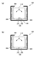
- FIG. 1 is an explanatory view schematically showing a configuration of an optical unit with a shake correction function according to Embodiment 1 of the present invention.
- FIGS. 1 (a) and 1 (b) show a support plate and steel of a movable module. It is explanatory drawing at the time of comprising a rocking fulcrum with a ball
- an optical unit 100 with a shake correction function of this embodiment includes a fixed body 200, a movable module 10 (imaging unit 1) that holds optical elements such as a lens and an imaging element, and the movable module 10.
- a swing fulcrum 180 that is swingably supported and a shake correction drive mechanism 500 that swings the movable module 10 about the swing fulcrum 180 are provided.
- a spring member 600 that biases the movable module 10 toward the bottom of the fixed body 200 is provided between the movable module 10 and the fixed body 200, and the members constituting the swing fulcrum 180 are in close contact with each other. It is in.
- the oscillating fulcrum 180 is configured by a contact portion in the optical axis direction of two members between the bottom of the movable module 10 and the bottom of the fixed body 200, and has the same configuration as the pivot bearing. . More specifically, first, a hole 711 is formed in the bottom of the fixed body 200, and the steel ball 181 (sphere) is held by the hole 711. The steel ball 181 is in contact with the bottom of the movable module 10 by a convexly curved portion, and the movable module 10 can swing around a contact portion between the movable module 10 and the steel ball 181 as a fulcrum.
- the bottom of the movable module 10 is composed of a support plate 183 that is bonded and fixed to the movable module main body, and the support plate 183 and the steel ball 181 constitute a swing fulcrum 180.
- the support plate 183 is a rubber or a porous elastomer (rubber or resin). Made of elastic material.
- the contact portion in the optical axis direction between the two members is provided between the bottom of the movable module 10 and the bottom of the fixed body 200. Since the configured swing fulcrum 180 is used, it is not necessary to deform the members constituting the swing fulcrum 180 when the movable module 10 is swung. Therefore, the movable module 10 can be swung with a small force.
- the support plate 183 is made of an elastic material among the two members (the support plate 183 and the steel ball 181) constituting the swing fulcrum 180, the impact is made of an elastic material when an impact is applied. It can be absorbed by the support plate 183. Further, in the case of a member made of an elastic material (support plate 183), unlike a spring, vibration energy is converted into heat energy and absorbed. Therefore, resonance hardly occurs between the movable module 10 and the fixed body 200. Therefore, a situation in which the relative positional relationship between the movable module 10 and the fixed body 200 continues to change due to resonance can be avoided. Therefore, when servo control is performed, the control system oscillates even if the control gain is increased. Can be prevented.
- the displacement of the movable module 10 is detected by a photo reflector (not shown) between the bottom of the movable module 10 and the bottom of the fixed body 200, and the shake correction drive mechanism 500 is controlled based on the detection result. Even in this case, the shake correction drive mechanism 500 can be controlled appropriately.
- one member (steel ball 181) is a convexly curved portion to the other member (support plate 183). It touches. For this reason, the swing fulcrum 180 can be supported evenly regardless of the direction in which the movable module 3 swings.
- the curved shape effectively absorbs an impact as compared with an acute angle support, only one of the two members (the support plate 183 and the steel ball 181) is made of an elastic material. A configuration can be employed. Note that both of the two members (support plate 183 and steel ball 181) constituting the swing fulcrum 180 may be made of an elastic material.
- a spring member 600 that biases the movable module 10 toward the bottom of the fixed body 200 is provided between the movable module 10 and the fixed body 200. For this reason, since the movable module 10 side and the fixed body 200 side are in close contact with each other, resonance of the movable module 10 can be prevented.
- the swing fulcrum 180 is configured by the support plate 183 on the movable module 10 side and the steel ball 181 located on the bottom side of the fixed body 200, but FIG. As shown in FIG. 6, the swing fulcrum 180 may be configured by the convex portion 186 and the support plate 183 that protrude from the bottom portion of the fixed body 200 toward the movable module 10 with a curved tip portion.
- the rocking fulcrum 180 formed by the contact portion in the optical axis direction of the two members (the support plate 183 and the convex portion 186) is provided between the bottom of the movable module 10 and the bottom of the fixed body 200. Therefore, when the movable module 10 is swung, it is not necessary to deform the member constituting the swing fulcrum 180. Therefore, the movable module 10 can be swung with a small force.
- the support plate 183 is made of an elastic material among the two members (the support plate 183 and the convex portion 186) constituting the swing fulcrum 180, the impact is made of an elastic material when an impact is applied. It can be absorbed by the support plate 183. Therefore, resonance hardly occurs between the movable module 10 and the fixed body 200.
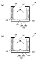
- FIG. 2 is an explanatory view schematically showing a configuration of an optical unit with a shake correction function according to Embodiment 2 of the present invention.
- FIGS. 2 (a) and 2 (b) show a support plate and steel of a fixed body. It is explanatory drawing at the time of comprising a rocking
- the basic configuration is the same as that of Embodiment 1 in both this embodiment and the embodiment described below, common portions are denoted by the same reference numerals and description thereof is omitted.
- the movable module 10 (the imaging unit 1) that holds the fixed body 200 and optical elements such as a lens and an imaging element. ), A swing fulcrum 180 for swingably supporting the movable module 10, and a shake correction drive mechanism 500 for swinging the movable module 10 about the swing fulcrum 180.
- a sensor detects the shake and controls the shake correction drive mechanism 500 based on the detection result of the sensor, The movable module 10 is swung around the swing fulcrum 180.
- the oscillating fulcrum 180 is constituted by a contact portion in the optical axis direction of two members between the bottom of the movable module 10 and the bottom of the fixed body 200. More specifically, first, a hole 185 is formed in the bottom of the movable module 10, and the steel ball 181 is held by the hole 185. The steel ball 181 is in contact with the bottom of the fixed body 200 by a convexly curved portion, and the movable module 10 can swing around the contact portion between the steel ball 181 and the bottom of the fixed body 200 as a fulcrum.
- the bottom of the fixed body 200 is composed of a support plate 188 that is bonded and fixed to the main body of the fixed body, and the support plate 188 and the steel ball 181 constitute a swing fulcrum 180.
- the support plate 188 is rubber or porous elastomer (rubber or resin). Made of elastic material.
- the light of the two members (the support plate 188 and the steel ball 181) between the bottom of the movable module 10 and the bottom of the fixed body 200 as in the first embodiment. Since the swing fulcrum 180 constituted by the contact portion in the axial direction is used, it is not necessary to deform the member constituting the swing fulcrum 180 when the movable module 10 is swung. Therefore, the movable module 10 can be swung with a small force.
- the support plate 188 is made of an elastic material among the two members (the support plate 188 and the steel ball 181) constituting the swing fulcrum 180, the impact is made of an elastic material when an impact is applied.
- one member (steel ball 181) is a convexly curved portion to the other member (support plate 188). It touches. For this reason, the swing fulcrum 180 can be supported evenly regardless of the direction in which the movable module 3 swings.
- the curved shape effectively absorbs an impact as compared with an acute support, only one of the two members (the support plate 188 and the steel ball 181) is made of an elastic material. The same effects as those of the first embodiment can be obtained, such as the configuration.
- the swing fulcrum 180 is configured by the support plate 188 on the fixed body 200 side and the steel ball 181 located at the bottom of the movable module 10, but in FIG. As shown, the swing fulcrum 180 may be constituted by a convex portion 187 that protrudes with a tip end curved toward the fixed body 200 from the bottom of the movable module 10 and a support plate 188.
- the rocking fulcrum 180 formed by the contact portion in the optical axis direction of the two members (the support plate 188 and the convex portion 187) is provided between the bottom of the movable module 10 and the bottom of the fixed body 200. Therefore, when the movable module 10 is swung, it is not necessary to deform the member constituting the swing fulcrum 180. Therefore, the movable module 10 can be swung with a small force.
- the support plate 188 is made of an elastic material among the two members (the support plate 188 and the convex portion 187) constituting the swing fulcrum 180, the impact is made of an elastic material when an impact is applied. It can be absorbed by the support plate 188.
- FIG. 3 is an explanatory view schematically showing the configuration of an optical unit with a shake correction function according to Embodiment 3 of the present invention.
- FIGS. 3 (a) and 3 (b) show the support plate and sphere of the movable module.
- FIG. 6 is an explanatory diagram in the case where the swing fulcrum is configured, and an explanatory diagram in the case where the swing fulcrum is configured by the support plate and the sphere of the fixed body.
- the swing fulcrum 180 has the bottom of the movable module 10 and the fixed body 200 as in the embodiment described with reference to FIG. It is comprised by the contact part in the optical axis direction of two members between the bottom parts. More specifically, first, a hole 711 is formed in the bottom of the fixed body 200, and the sphere 184 is held by the hole 711. The spherical body 184 is in contact with the bottom of the movable module 10 by a convexly curved portion, and the movable module 10 can swing around a contact portion between the movable module 10 and the spherical body 184 as a fulcrum.
- the bottom of the movable module 10 is composed of a support plate 183 bonded and fixed to the movable module main body, and the support plate 183 and the sphere 184 constitute a swing fulcrum 180.
- the support plate 183 is a rigid substrate such as a metal plate
- the sphere 184 is made of an elastic material such as rubber or porous elastomer (rubber or resin). Therefore, when an impact is applied, the impact can be absorbed by the sphere 184 made of an elastic material. Further, in the case of a member made of an elastic material (sphere 184), unlike a spring, vibration energy is converted into heat energy and absorbed. Therefore, the same effects as those of the first embodiment are obtained, such that resonance is unlikely to occur between the movable module 10 and the fixed body 200.
- the swing fulcrum 180 is configured by the support plate 183 on the movable module 10 side and the sphere 184 made of an elastic material.
- the swing fulcrum 180 may be configured by the support plate 188 (rigid substrate) on the body 200 side and the sphere 184 made of an elastic material.
- + X is attached to one side of the X axis
- -X is attached to the other side
- + Y is attached to one side of the Y axis
- -Y is attached to the other side
- one side of the Z axis is attached.
- + Z is attached to the side (opposite the subject side)
- -Z is attached to the other side (subject side).
- the form demonstrated below respond corresponds to the form demonstrated with reference to Fig.1 (a), FIG.1 (b), FIG.2 (a), (b) and FIG.3 (a), (b)
- the configuration described with reference to) can be configured in substantially the same manner.
- FIG. 4 is an explanatory diagram schematically showing a state in which the optical unit with a shake correction function according to the first embodiment of the present invention is mounted on an optical device such as a mobile phone.
- FIG. 5 is a perspective view showing the appearance and the like of the optical unit with a shake correction function according to the first embodiment of the present invention
- FIGS. 5A and 5B are views when the optical unit is viewed from the subject side. It is a perspective view and a perspective view when the optical unit is viewed from the opposite side to the subject side.
- An optical unit 100 (an optical unit with a shake correction function) shown in FIG. 4 is a thin camera used in an optical device 1000 such as a mobile phone with a camera, and is supported by a chassis 1100 (device main body) of the optical device 1000. It is mounted with.
- a shake such as a hand shake occurs in the optical apparatus 1000 during shooting, the captured image is disturbed. Therefore, in the optical unit 100 of the present embodiment, as will be described later, a movable module including the imaging unit 1 is supported so as to be swingable within the fixed body 200, and a gyroscope (not shown) mounted on the optical unit 100 is supported.
- a shake correction drive mechanism swings the imaging unit 1. Not shown).
- flexible wiring boards 410 and 420 for feeding power to the imaging unit 1 and the shake correction drive mechanism are drawn out from the optical unit 100.
- Reference numeral 420 is electrically connected to an upper control unit or the like provided on the main body side of the optical apparatus 1000 via a common connector 490 or the like.
- the flexible wiring board 410 also has a function of outputting a signal from the imaging unit 1. For this reason, since the flexible wiring board 410 has a large number of wires, a flexible wiring board 410 having a relatively wide width is used.
- FIG. 6 is a cross-sectional view schematically showing the configuration of the imaging unit 1 mounted on the optical unit 100 with a shake correction function according to Embodiment 1 of the present invention.
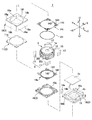
- FIG. 7 is an exploded perspective view of the imaging unit 1 mounted on the optical unit 100 with a shake correction function according to Embodiment 1 of the present invention.
- the imaging unit 1 includes a plurality of lenses 1a (see FIG. 4) as optical elements in the A direction (front side) approaching the subject (object side) along the optical axis L direction. ), And an optical element unit that moves in both directions in the B direction (rear side) approaching the side opposite to the subject (imaging element side / image side), and has a substantially rectangular parallelepiped shape.
- the imaging unit 1 generally includes a moving body 3 that holds a plurality of lenses 1a (see FIG. 4) and an optical element such as a fixed aperture inside, and a lens drive that moves the moving body 3 along the optical axis L direction.
- the moving body 3 includes a cylindrical lens holder 12 that holds a lens 1 a and a fixed diaphragm (not shown), and a coil holder 13 that holds the lens holder 12 on the inner side.
- the lens driving coils 30s and 30t constituting the lens driving mechanism 5 are held.
- the support 2 is positioned on the opposite side to the subject side ( ⁇ Z side), and a spring holder 19 that holds a spring, which will be described later, and the mounting substrate 15 is positioned on the opposite side of the subject side ( ⁇ Z side) with respect to the spring holder 19.
- An image sensor 1b is mounted on the substrate surface 151 facing the subject.
- the spring holder 19 holds a filter 1c such as an infrared filter.
- incident windows 11a and 18a for taking in light from the subject into the lens 1a are formed.
- windows 16a and 19a for guiding incident light to the image sensor 1b are formed in the center of the substrate holder 16 and the spring holder 19.
- the case 18 is made of a ferromagnetic plate such as a steel plate and also functions as a yoke. For this reason, the case 18 constitutes a linkage magnetic field generator that generates a magnetic field interlinking the lens drive coils 30s and 30t together with the lens drive magnet 17 described later.
- the lens driving mechanism 5 is configured together with the lens driving coils 30 s and 30 t wound around the outer peripheral surface of the coil holder 13.
- the support body 2 and the moving body 3 are connected to each other via a spring member 14t and a metal spring member 14s provided at positions separated in the optical axis direction.
- a spring member 14s is used on the imaging element 1b side
- a spring member 14t is used on the subject side.
- the spring members 14 s and 14 t have the same basic configuration, and an outer peripheral side connecting portion 141 held on the support body 2 side, an annular inner peripheral side connecting portion 142 held on the movable body 3 side, A narrow arm portion 143 that connects the outer peripheral side connecting portion 141 and the inner peripheral side connecting portion 142 is provided.
- the outer peripheral side connecting part 141 is held by the spring holder 19, and the inner peripheral side connecting part 142 is connected to the imaging element side end of the coil holder 13 of the moving body 3.
- the arm portion 143 extends in an arc shape in the circumferential direction.
- the outer peripheral side connecting portion 141 is held by the spacer 11, and the inner peripheral side connecting portion 142 is connected to the subject side end of the coil holder 13 of the moving body 3.
- the arm portion 143 extends in an arc shape in the circumferential direction while meandering in the radial direction.
- the moving body 3 is supported by the support body 2 via the spring members 14s and 14t so as to be movable in the direction of the optical axis.
- the spring members 14s and 14t are both made of nonmagnetic metal such as beryllium copper or nonmagnetic SUS steel, and are formed by pressing a thin plate having a predetermined thickness or etching using a photolithography technique. is there.
- the spring member 14s is divided into two spring pieces, and each end of the lens driving coils 30s and 30t is connected to the spring piece.
- terminals 14a and 14b are connected to the two spring pieces, respectively, and the spring member 14s also functions as a power supply member for the lens driving coils 30s and 30t.
- a ring-shaped magnetic piece 61 is held at the subject side end of the coil holder 13, and the position of the magnetic piece 61 is a position on the subject side with respect to the lens driving magnet 17. For this reason, the magnetic piece 61 applies a biasing force in the direction of the optical axis L to the moving body 3 by an attractive force acting between the magnetic piece 61 and the lens driving magnet 17. For this reason, at the time of non-energization (origin position), the lens holder 12 can be placed still on the image sensor 1b side by the attractive force of the lens driving magnet 17 and the magnetic piece 61.
- the magnetic piece 61 acts as a kind of yoke, and can reduce leakage magnetic flux from a magnetic path formed between the lens driving magnet 17 and the lens driving coils 30s and 30t.
- a rod-like or spherical magnetic body may be used as the magnetic piece 61. If the magnetic piece 61 is formed in a ring shape, there is an effect that the attractive force attracting the lens driving magnet 17 when the lens holder 12 moves in the optical axis direction is isotropic. Further, when the lens driving coils 30 s and 30 t are energized, the magnetic piece 61 moves in a direction away from the lens driving magnet 17, so that no extra force is exerted to press the lens holder 12 toward the image sensor 1 b. Therefore, the lens holder 12 can be moved in the optical axis direction with a small amount of electric power.
- the lens 1a when viewed from the direction of the optical axis L, the lens 1a (see FIG. 4) is circular, but the case 18 used for the support 2 has a rectangular box shape. Accordingly, the case 18 includes a rectangular tube-shaped body portion 18c, and an upper plate portion 18b having an incident window 18a formed on the upper surface side of the rectangular tube-shaped body portion 18c.
- a lens driving magnet 17 is fixed to a side surface corresponding to a square corner inside the rectangular cylindrical body portion 18c, and each of the lens driving magnets 17 is composed of a triangular prism-like permanent magnet.
- Each of the four lens driving magnets 17 is divided into two in the direction of the optical axis, and in any case, the inner surface and the outer surface are magnetized to different poles. For this reason, the winding directions of the two lens driving coils 30 s and 30 t are opposite to each other around the coil holder 13.
- the moving body 3 configured as described above is disposed inside the case 18.
- the lens driving coils 30 s and 30 t each constitute the lens driving mechanism 5 so as to face the lens driving magnet 17 fixed to the inner surface of the rectangular tubular body 18 c of the case 18.
- the moving body 3 is normally located on the imaging element side (one side in the Z-axis direction). In such a state, the moving body 3 is directed to the lens driving coils 30s and 30t in a predetermined direction.
- the lens driving coils 30s and 30t each receive an electromagnetic force directed toward the subject side (the other side in the Z-axis direction). Accordingly, the moving body 3 to which the lens driving coils 30s and 30t are fixed starts to move toward the subject side (front side). At this time, an elastic force that restricts the movement of the moving body 3 is generated between the spring member 14 t and the front end of the moving body 3 and between the spring member 14 s and the rear end of the moving body 3.
- the moving body 3 stops. At this time, the moving body 3 can be stopped at a desired position by adjusting the amount of current flowing through the lens driving coils 30 s and 30 t according to the elastic force acting on the moving body 3 by the spring members 14 s and 14 t. .
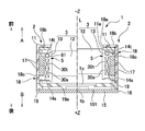
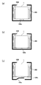
- FIG. 8 is a cross-sectional view showing the internal structure of the optical unit 100 with a shake correction function according to the first embodiment of the present invention
- FIGS. 8A and 8B are YZ cross-sectional views of the optical unit 100
- 2 is an XZ sectional view of the optical unit 100.
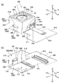
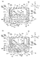
- FIG. 9 is an exploded perspective view of the optical unit 100 with a shake correction function according to the first embodiment of the present invention when viewed from the subject side
- FIG. 10 is a shake correction function according to the first embodiment of the present invention. It is a disassembled perspective view when the attached optical unit 100 is seen from the object opposite side.
- the optical unit 100 includes a fixed body 200, an imaging unit 1, a spring member 600 that is supported by the fixed body 200 so as to be displaceable, and an imaging unit.
- a shake correction drive mechanism 500 that generates a magnetic drive force that causes the imaging unit 1 to be displaced relative to the fixed body 200 between the unit 1 and the fixed body 200 is provided.
- the outer peripheral portion of the imaging unit 1 is composed of a case 18 (see FIG. 7) used for the support 2 in the imaging unit 1.
- the fixed body 200 includes an upper cover 250, a spacer 280, and a lower cover 700, and the upper cover 250 includes a rectangular tubular body 210 surrounding the imaging unit 1 and an opening on the subject side of the rectangular tubular body 210. And an end plate part 220 for closing the part.
- the end plate 220 is formed with a window 220a through which light from the subject enters.
- the end of the rectangular tubular body 210 opposite to the subject (+ Z side
- a notch 219 is formed on a surface located on one side + Y in the Y-axis direction of two surfaces facing each other in the Y-axis direction in the rectangular tubular body 210, and the notch 219 is flexible. This is used when the wiring board 420 is connected to a terminal portion of a sheet-like coil 550 described later. Further, notches 218 used for engagement with a spacer 280 described later are formed on the four surfaces of the rectangular tube-shaped body portion 210, and two of the notches 218 located in the Y-axis direction are formed. The notch 218 is connected to the notch 219 to form an integral notch.
- a notch 217 connected to the notch 218 is formed on the lower end side of two locations facing each other in the Y-axis direction.
- the Y-axis The notch 217 on one side + Y in the direction is used to pull out the flexible wiring board 410 to the outside.
- the spacer 280 includes a rectangular frame portion 281 that is sandwiched between the rectangular tubular body 210 of the upper cover 250 and the lower cover 700, and a columnar portion 283 that protrudes from the corner portion of the frame portion 281 toward the subject. , And an engaging protrusion 285 that protrudes outward at the side portion of the frame portion 281.
- the engaging protrusion 285 is engaged with the notch 218 cut out in a square shape in the rectangular tube-shaped body 210 of the upper cover 250, and the spacer 280 and the Positioning with the cover 250 is performed.
- the lower cover 700 is a press-processed product for a metal plate, and includes a substantially rectangular bottom plate portion 710 and four side plate portions 720 that stand from the outer peripheral edge of the bottom plate portion 710 toward the subject.
- the side plate part 720 sandwiches the frame part 281 of the spacer 280 between the square cylindrical body part 210 of the upper cover 250.
- a notch 728 is formed in the side plate portion 720 located on one side + Y in the Y-axis direction, and the center portion of the notch 728 has the side plate portion 720. A part is left as a plate-like protrusion 729.
- a window-shaped notch 726 is also formed in the side plate portion 720 located on the other side ⁇ Y in the Y-axis direction of the side plate portion 720, and the side plate portion 720 is formed at the center of the notch 726. Is left as a crosspiece 727.
- the cutout 728 is used to pull out the flexible wiring substrate 410 to the outside, as will be described later.
- the cutout 726 interferes with the side plate portion 720 of the lower cover 700. It is used to prevent from doing.
- the bottom plate portion 710 of the lower cover 700 has a hole 711 formed at the center thereof, and is positioned adjacent to the hole 711 on the other side ⁇ X in the X-axis direction and to the hole 711 in the Y-axis direction.
- Concave portions 716 and 717 that are recessed in a rectangular shape are formed at positions adjacent to each other on the other side -Y.
- the inner surfaces of the bottom portions 716a and 717a of the recesses 716 and 717 are substantially mirror surfaces, and the bottom portions 716a and 717a are first mounted on the substrate surface 152 on the mounting substrate 15 opposite to the subject side. This is used as a reflection surface for the photo reflector 580 and the second photo reflector 590.
- the lower cover 700 is made of a metal part that has been made nonmagnetic by heat treatment. More specifically, the lower cover 700 is made of a metal part obtained by bending or drawing a metal material such as SUS304 into a predetermined shape.
- a metal material such as SUS304 or the like
- a part of austenite is transferred to martensite and has magnetism, but in this embodiment, the lower cover is subjected to heat treatment after bending or drawing and the like. 700 is earned. For this reason, when the optical unit 100 is assembled, it is possible to prevent the permanent magnet 520 and the lower cover 700 from being attracted.
- heat treatment is performed on a metal material such as SUS304, the reflectance increases, so the lower cover 700 has sufficient reflectance to be used as a reflective surface for the first photoreflector 580 and the second photoreflector 590. ing.
- a swing fulcrum for swinging the imaging unit 1 between the imaging unit 1 and the lower cover 700 of the fixed body 200 180 is provided, and the imaging unit 1 is biased toward the lower cover 700 by the spring member 600 via the swing fulcrum 180.
- the swing fulcrum 180 is configured by a steel ball 181 positioned in a hole 711 formed in the bottom plate portion 710 of the lower cover 700 and a support plate 183 fixed to the board surface 152 of the mounting board 15.
- the imaging unit 1 can swing around the position of contact between the steel ball 181 and the support plate 183 as a swing center.
- the support plate 183 is made of an elastic material such as rubber.
- the spring member 600 includes a fixed-side connection portion 620 that is sandwiched between the side plate portion 720 of the lower cover 700 and the frame portion 281 of the spacer 280 in the fixed body 200, and a movable-side connection portion 610 that is connected to the imaging unit 1.
- the plate-like spring member is provided with a plurality of arm portions 630 extending between the movable side connecting portion 610 and the fixed side connecting portion 620, and both ends of the arm portion 630 are respectively connected to the movable side connecting portion 610 and the fixed portion. It is connected to the side connecting part 620.
- the movable side connecting portion 610 of the spring member 600 is fixed to a step portion 168 formed on the outer peripheral side of the substrate holder 16 on the rear end side of the imaging unit 1.
- the spring member 600 is made of a nonmagnetic metal such as beryllium copper or a nonmagnetic SUS steel material, and is formed by pressing a thin plate having a predetermined thickness or etching using a photolithography technique.
- the imaging unit 1 is closer to the subject side than the steel ball 181. Is placed, the imaging unit 1 is pushed up to the subject side by the steel ball 181. Therefore, in the spring member 600, the movable side connecting portion 610 is pushed up to the subject side relative to the fixed side connecting portion 620, and the arm portion 630 of the spring member 600 moves the imaging unit 1 to the opposite side to the subject side. Energize.
- the imaging unit 1 is biased toward the bottom plate portion 710 of the lower cover 700 by the spring member 600 via the swing fulcrum 180, and the imaging unit 1 can swing by the swing fulcrum 180. It will be in the state supported by the fixed body 200 in the state.
- the shake correction drive mechanism 500 is configured by the coil unit 560 and the permanent magnet 520 that generates a magnetic field linked to the coil unit 560.
- flat permanent magnets 520 are respectively fixed to the four outer surfaces 18 e, 18 f, 18 g, and 18 h of the rectangular tubular body 18 c of the case 18, and the corners of the upper cover 250 are fixed.
- Coil portions 560 are disposed on the inner surfaces 211, 212, 213, and 214 of the cylindrical body portion 210. Permanent magnet 520 is magnetized with different poles on the outer surface side and inner surface side.
- the permanent magnet 520 is composed of two magnet pieces arranged in the direction of the optical axis L, and the magnet pieces are magnetized to poles having different surfaces on the side facing the coil portion 560. Moreover, the coil part 560 is formed in the square frame shape, and an upper and lower long side part is utilized as an effective side.
- the permanent magnets 520 and the coil portions 560 disposed at two positions sandwiching the imaging unit 1 on both sides in the Y-axis direction constitute a Y-side shake correction drive mechanism 500y.
- the imaging unit 1 is swung around an axis line X0 extending in the X-axis direction through the swinging fulcrum 180.
- the permanent magnet 520 and the coil unit 560 arranged at two positions sandwiching the imaging unit 1 on both sides in the X-axis direction constitute an X-side shake correction drive mechanism 500x, and an arrow Y1 in FIG.
- the imaging unit 1 is swung around an axis Y0 extending in the Y-axis direction through the swing fulcrum 180.
- sheet coils extending along the four inner surfaces 211, 212, 213, and 214 of the upper cover 250 are used.
- 550 is used, and in the sheet-like coil 550, four coil portions 560 are integrally formed with a predetermined interval.
- the sheet-like coil 550 has a shape extending in a band shape when unfolded, and is folded along the four inner surfaces 211, 212, 213, and 214 of the upper cover 250, and the inner surface 211 of the upper cover 250. To 214 by surface bonding or the like. In this state, both end portions 551 and 552 of the sheet coil 550 are close to each other through the slit 555.
- the sheet-like coil 550 has a structure in which a coil portion 560 made of fine copper wiring is formed on a printed circuit board using a conductive wiring technique, and a plurality of layers of copper wiring (coil portion 560) is an insulating film. Are formed in multiple layers. The surface of the copper wiring (coil portion 560) is also covered with an insulating film.
- an FP coil Fe Pattern Coil (registered trademark) manufactured by Asahi Kasei Electronics Corporation can be exemplified.
- one end portion 551 of the sheet-like coil 550 is formed with a protruding portion 553 that protrudes in a rectangular shape on the opposite side to the subject side, and the protruding portion 553 includes four coil portions 560.
- a plurality of terminal portions 565 are formed by the extending conductive layer.
- the terminal portion 565 faces the outer side opposite to the inner side facing the permanent magnet 520 in the sheet-like coil 550.
- a cutout 219 is formed in the upper cover 250 at a portion overlapping the terminal portion 565.
- the terminal part 565 (projection part 553) of the sheet-like coil 550 is exposed on the outer surface, the sheet-like coil 550 and the flexible wiring board 420 are directed toward the optical axis L in the notch 219.
- the bent end portion 425 is electrically connected by solder or the like.
- the imaging unit 1 is supported by the fixed body 200 so as to be swingable by the swing support point 180. Accordingly, when a large force is applied from the outside and the imaging unit 1 swings greatly, the arm portion 630 of the spring member 600 may be plastically deformed.
- the sheet coil 550 and the permanent magnet 520 are opposed to each other through a narrow gap. In the case of the sheet-like coil 550, unlike the air-core coil, the winding cannot be unwound even if it contacts the permanent magnet 520.
- the movable range in the X-axis direction and the Y-axis direction intersecting the optical axis L of the imaging unit 1 is regulated by the contact between the sheet-like coil 550 and the permanent magnet 520, No other stopper mechanism is provided to prevent the imaging unit 1 from swinging.
- the sheet-like coil 550 since the sheet-like coil 550 is used, the distance between the imaging unit 1 and the fixed body 200 can be reduced as compared with the case where a single air-core coil is used. The size of 100 can be reduced.
- the sheet-like coil 550 since the plurality of coil portions 560 are integrally provided with the terminal portion 565, even when the coil portions 560 are arranged at a plurality of locations around the optical axis L, the sheet-like coil 550 is light-transmitted. What is necessary is just to make it extend around the axis L.
- the sheet-like coil 550 since the terminal portion 565 is directed to the outer side opposite to the side facing the permanent magnet 520, electrical connection to the coil portion 560, that is, a flexible wiring board to the terminal portion 565 is provided. 420 can be easily connected.
- the Y-side shake correction drive mechanism 500 y swings the imaging unit 1 around the X axis about the swing fulcrum 180. Further, if the swinging of the imaging unit 1 around the X axis and the swinging around the Y axis are combined, the imaging unit 1 can be displaced with respect to the entire XY plane. Therefore, all shakes assumed in the optical unit 100 can be reliably corrected.
- the displacement of the image pickup unit 1 is monitored by a first photo reflector 580 and a second photo reflector 590 as described later with reference to FIGS. 11 and 9.
- one end of the flexible wiring board 410 is connected to the mounting board 15 of the imaging unit 1, and the flexible wiring board 410 is moved when the imaging unit 1 is swung. When a load is applied to 1, there is a problem in properly swinging the imaging unit 1.
- the flexible wiring board 410 has a main body portion 415 positioned outside the optical unit 100 so that the connector 490 can be mounted and the flexible wiring board 420 can be connected, but the flexible wiring board 410 is positioned inside the optical unit 100.
- the portion is a belt-like portion 411 having a narrower width dimension than the main body portion 415.
- the band-like portion 411 extends from the one side + Y in the Y-axis direction toward the other side ⁇ Y, and then is folded back toward the one side + Y. After that, the end portion is mounted along the edge of the mounting substrate 15. The substrate 15 is folded and fixed toward the substrate surface on the subject side.
- the flexible wiring substrate 410 has a long dimension because the folded portion 413 is provided between the external main body portion 415 and the portion fixed to the mounting substrate 15. Accordingly, the strip-like portion of the flexible wiring board 410 smoothly follows the shake of the imaging unit 1, so that a large load is not applied to the imaging unit 1.
- the strip-shaped portion 411 of the flexible wiring board 410 is formed with a slit 418 extending along the extending direction (Y-axis direction) of the strip-shaped portion 411 in the middle of the length direction.
- the middle portion is divided into two narrow portions 416 and 417 in the width direction. For this reason, the rigidity of the strip-shaped portion 411 is relaxed. Accordingly, the strip-like portion of the flexible wiring board 410 smoothly follows the shake of the imaging unit 1, so that a large load is not applied to the imaging unit 1.
- the band-like portion 411 of the flexible wiring board 420 overlaps with the imaging unit 1 in the optical axis L direction, but the portion overlapping the swing fulcrum 180 is a circular hole 414 connected to the slit 418. For this reason, even if the belt-like portion 411 of the flexible wiring board 420 is arranged at a position overlapping the imaging unit 1 in the optical axis L direction, there is no problem in providing the swing fulcrum 180.
- the side plate portion 720 located on one side + Y in the Y-axis direction among the side plate portions 720 of the lower cover 700 is formed with a notch 728 for pulling out the band-like portion 411 of the flexible wiring board 420.
- a part of the side plate portion 720 is left as a plate-like protrusion 729 at the center portion.
- an elliptical hole 419 is formed in the band-like portion 411 of the flexible wiring board 420 at a portion overlapping the plate-like protrusion 729. Therefore, when the strip-like portion 411 of the flexible wiring board 420 is pulled out from the notch 728 of the side plate portion 720, the plate-like protrusion 729 can be passed through the hole 419. There is no hindrance to pull out. Further, since the plate-like protrusion 729 is fitted into the hole 419, the band-like portion 411 of the flexible wiring board 420 can be positioned.
- a window-shaped notch 726 is formed in the side plate portion 720 located on the other side ⁇ Y in the Y-axis direction among the side plate portions 720 of the lower cover 700.
- the folded portion 413 of the flexible wiring board 410 is at the same height as the swing center of the imaging unit 1 at the swing fulcrum 180 (contact position between the steel ball 181 and the support plate 183). For this reason, the displacement of the belt-like portion 411 when the imaging unit 1 swings can be suppressed to a small value.
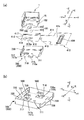
- FIG. 11 is an explanatory diagram of a photo reflector provided in the optical unit 100 with a shake correction function according to the first embodiment of the present invention.
- FIGS. 11 (a) and 11 (b) show the subject side in the optical unit 100.
- FIG. 4 is an exploded perspective view of the opposite side portion and an explanatory view showing the positional relationship between the photo reflector and the reflecting surface.
- the optical unit 100 with a shake correction function of this embodiment there is a fluctuation between the mounting board 15 constituting the bottom of the imaging unit 1 and the lower cover 700 of the fixed body 200.
- a moving fulcrum 180 is configured, and a first photo reflector 580 and a second photo reflector 590 are mounted on the substrate surface 152 facing the lower cover 700 in the mounting substrate 15.
- two concave portions 716 and 717 are formed in the bottom plate portion 710 of the lower cover 700, and the inner surfaces of the bottom portions 716 a and 717 a of the concave portions 716 and 717 correspond to the first photo reflector 580 and the second photo reflector 590.
- a first reflecting portion 716c and a second reflecting portion 717c are provided.
- the first photo reflector 580 and the second photo reflector 590 both have a rectangular planar shape when viewed from the direction of the optical axis L.
- the first photo reflector 580 and the second photo reflector 590 are both A light emitting portion is provided at one end portion in the longitudinal direction, and a light receiving portion is provided at the other end portion in the longitudinal direction.
- a light shielding portion is formed between the light emitting portion and the light receiving portion.
- the first photo reflector 580 is disposed at a position overlapping the axis X0 described with reference to FIG. 8B in the optical axis L direction, and the light emission center and the light reception center of the first photo reflector 580 are Are arranged in a direction perpendicular to the optical axis L at positions symmetrical to the axis X0.
- the second photo reflector 590 is disposed at a position overlapping the axis Y0 described with reference to FIG. 8A in the direction of the optical axis L, and the light emission center and the light reception center of the second photo reflector 590 are the axis lines. It overlaps Y0 in the optical axis L direction.
- the first photo reflector 580 and the second photo reflector 590 are arranged so that the long sides extend in the Y-axis direction, and are parallel to the extending direction of the strip-shaped portion 411 of the flexible wiring board 410. Therefore, the first photo reflector 580 and the second photo reflector 590 have short sides extending in the width direction of the flexible wiring board 410. For this reason, even when the second photo reflector 590 is arranged at a position overlapping the slit 418 of the flexible wiring board 410 so that the second photo reflector 590 and the flexible wiring board 410 do not overlap in the optical axis L direction. The width dimension of the slit 418 can be narrowed.
- a notch 416a is formed in the outer edge portion of the narrow width portion 416, and the first photo reflector 580 is disposed at a position overlapping with the notch 416a.
- the width dimension of the notch 416a can be reduced. Therefore, a position that overlaps the first photo reflector 580 and the second photo reflector 590 in the direction of the optical axis L between the bottom of the imaging unit 1 (the mounting substrate 15) and the lower cover 700 of the fixed body 200 is avoided. Even when the strip portion 411 of the flexible wiring board 410 is extended in the Y-axis direction, the width of the strip portion 411 is relatively large.
- the first photoreflector 580 and the second photoreflector 590 configured as described above, when the mounting substrate 15 and the bottom plate portion 710 of the lower cover 700 are parallel to each other, as shown in FIG.
- the light emitted from the light emitting unit is reflected by the first reflecting unit 716c and received by the light receiving unit of the first photo reflector 580 with high intensity, and the light emitted from the light emitting unit of the second photo reflector 590 is The light is reflected by the second reflecting portion 717c and received by the light receiving portion of the second photo reflector 590 with high intensity.
- the light receiving intensity at the light receiving portion of the first photo reflector 580 and the light receiving intensity at the light receiving portion of the second photo reflector 590 are non-parallel. Decreases. Further, the light reception intensity at the light receiving portion of the first photo reflector 580 and the light reception intensity at the light receiving portion of the second photo reflector 590 vary depending on the direction of the inclination of the imaging unit 1 with respect to the fixed body 200.
- the shake correction drive The imaging unit 1 can be properly swung by the mechanism 500.
- the first photo reflector 580 is disposed at a position overlapping the axis X0 in the optical axis L direction
- the second photo reflector 590 is disposed at a position overlapping the axis Y0 in the optical axis L direction.
- the shake correction drive mechanism 500 that swings the imaging unit 1 as the movable module is provided. Therefore, when shake such as hand shake occurs in the optical unit 100.
- the imaging unit 1 can be swung so as to cancel out such a shake. For this reason, even if the optical unit 100 is shaken, the inclination of the optical axis L can be corrected.
- the contact portion in the optical axis direction of the two members is provided between the bottom of the movable module 10 and the bottom of the fixed body 200. Since the configured swing fulcrum 180 is used, it is not necessary to deform the members constituting the swing fulcrum 180 when the movable module 10 is swung. Therefore, the movable module 10 can be swung with a small force. Moreover, in this embodiment, since the support plate 183 is made of an elastic material among the two members (the support plate 183 and the steel ball 181) constituting the swing fulcrum 180, the impact is made of an elastic material when an impact is applied.
- the displacement of the movable module 10 is detected by the first photo reflector 580 and the second photo reflector 590 between the bottom of the movable module 10 and the bottom of the fixed body 200, and the shake correction drive mechanism is based on the detection result. Even when 500 is controlled, the effects described with reference to FIG. 1A are obtained, such as the shake correction drive mechanism 500 being appropriately controlled.
- the folded portion 413 of the flexible wiring board 410 is at the same height as the swing center of the imaging unit 1 at the swing fulcrum 180 (contact position between the steel ball 181 and the support plate 183). For this reason, the displacement of the belt-like portion 411 when the imaging unit 1 swings can be suppressed to a small value. Accordingly, since the influence of the flexible wiring board 410 on the imaging unit 1 can be reduced, the imaging unit 1 can be rocked with high accuracy.
- the shake correction drive mechanism 500 is provided between the outer peripheral surface of the imaging unit 1 and the fixed body 200 (upper cover 250), while the first photo reflector 580 and the second photo reflector 590 are swung.
- the fulcrum 180 is provided using the space between the bottom (mounting substrate 15) of the imaging unit 1 and the fixed body 200 (lower cover 700). For this reason, even when a photo reflector (first photo reflector 580 and second photo reflector 590), a swing fulcrum 180, and a shake correction drive mechanism 500 are provided for the imaging unit 1, the optical axis L direction and the optical axis direction are provided. Can be prevented from increasing in size in the direction intersecting (X-axis direction and Y-axis direction).
- the present invention may be applied to the optical unit 100 used in the camera-equipped mobile phone.
- the present invention may be applied to the optical unit 100 used in a thin digital camera or the like.
- the lens drive mechanism 5 which magnetically drives the moving body 3 containing the lens 1a to an optical axis direction is supported on the support body 2 in the imaging unit 1.
- the present invention may be applied to a fixed focus type optical unit in which the lens driving mechanism 5 is not mounted on the imaging unit 1.
- the optical unit 100 with a shake correction function to which the present invention is applied is fixed in a device having vibrations at regular intervals, such as a refrigerator or the like, in addition to a mobile phone, a digital camera, etc. It can also be used for a service that can obtain information inside the refrigerator when going out, for example, when shopping. In such a service, since it is a camera system with a posture stabilization device, a stable image can be transmitted even if the refrigerator vibrates. Further, the present apparatus may be fixed to a device worn at the time of attending school, such as a student's bag, a student's bag, a school bag, or a hat.
- the guardian or the like can observe the image in a remote place to ensure the safety of the child.
- a clear image can be taken even if there is vibration during movement without being aware of the camera.
- a GPS is installed in addition to the camera module, the location of the target person can be acquired at the same time. In the event of an accident, the location and situation can be confirmed instantly.
- the optical unit 100 with a shake correction function to which the present invention is applied is mounted at a position where the front can be photographed in an automobile, it can be used as a drive recorder.
- the optical unit 100 with a shake correction function to which the present invention is applied is mounted at a position where the front of the vehicle can be photographed, and peripheral images are automatically photographed at regular intervals and automatically transferred to a predetermined server. Also good. Further, by distributing this image in conjunction with traffic jam information such as car navigation VICS (Vehicle Information and Communication System), it is possible to provide a more detailed traffic situation. According to such a service, it is possible to record the situation at the time of an accident or the like by an unintentional third party and use it for inspection of the situation as in the case of a drive recorder mounted on a car. In addition, a clear image can be acquired without being affected by the vibration of the automobile. In such an application, when the power is turned on, a command signal is output to the control unit, and shake control is started based on the command signal.
- VICS Vehicle Information and Communication System
- the optical unit 100 with a shake correction function to which the present invention is applied may be applied to shake correction of an optical device that emits light, such as a laser pointer, a portable or vehicle-mounted projection display device, or a direct-view display device. Good. Further, it may be used for observation without using an auxiliary fixing device such as a tripod for observation at a high magnification such as an astronomical telescope system or a binoculars system. In addition, by using a sniper rifle or a gun barrel such as a tank, the posture can be stabilized against vibration at the time of triggering, so that the accuracy of hitting can be improved.
Landscapes
- Physics & Mathematics (AREA)
- General Physics & Mathematics (AREA)
- Optics & Photonics (AREA)
- Engineering & Computer Science (AREA)
- Multimedia (AREA)
- Signal Processing (AREA)
- Adjustment Of Camera Lenses (AREA)
- Studio Devices (AREA)
- Lens Barrels (AREA)
Priority Applications (2)
| Application Number | Priority Date | Filing Date | Title |
|---|---|---|---|
| US13/813,229 US9116361B2 (en) | 2010-08-06 | 2011-07-22 | Optical unit with shake correcting function |
| CN201180037547.3A CN103052909B (zh) | 2010-08-06 | 2011-07-22 | 带抖动修正功能的光学单元 |
Applications Claiming Priority (2)
| Application Number | Priority Date | Filing Date | Title |
|---|---|---|---|
| JP2010-177010 | 2010-08-06 | ||
| JP2010177010A JP5771373B2 (ja) | 2010-08-06 | 2010-08-06 | 振れ補正機能付き光学ユニット |
Publications (1)
| Publication Number | Publication Date |
|---|---|
| WO2012017839A1 true WO2012017839A1 (ja) | 2012-02-09 |
Family
ID=45559345
Family Applications (1)
| Application Number | Title | Priority Date | Filing Date |
|---|---|---|---|
| PCT/JP2011/066682 Ceased WO2012017839A1 (ja) | 2010-08-06 | 2011-07-22 | 振れ補正機能付き光学ユニット |
Country Status (4)
| Country | Link |
|---|---|
| US (1) | US9116361B2 (enExample) |
| JP (1) | JP5771373B2 (enExample) |
| CN (1) | CN103052909B (enExample) |
| WO (1) | WO2012017839A1 (enExample) |
Cited By (3)
| Publication number | Priority date | Publication date | Assignee | Title |
|---|---|---|---|---|
| WO2013118503A1 (ja) * | 2012-02-10 | 2013-08-15 | パナソニック株式会社 | レンズアクチュエータ |
| TWI744403B (zh) * | 2016-11-10 | 2021-11-01 | 日商日本電產三協股份有限公司 | 光學單元 |
| US11888374B2 (en) * | 2019-08-02 | 2024-01-30 | Tdk Taiwan Corp. | Optical element driving mechanism |
Families Citing this family (35)
| Publication number | Priority date | Publication date | Assignee | Title |
|---|---|---|---|---|
| JP5828660B2 (ja) * | 2011-04-11 | 2015-12-09 | 日本電産サンキョー株式会社 | 振れ補正機能付き光学ユニット |
| JP6046427B2 (ja) * | 2012-09-19 | 2016-12-14 | 日本電産サンキョー株式会社 | 光学ユニット |
| GB201221306D0 (en) * | 2012-11-27 | 2013-01-09 | Cambridge Mechatronics Ltd | Suspension system for a camera lens element |
| CN110187590B (zh) * | 2013-05-29 | 2022-06-10 | Lg伊诺特有限公司 | 镜头驱动装置、照相机模块和移动电话 |
| US9285566B2 (en) | 2013-08-08 | 2016-03-15 | Apple Inc. | Mirror tilt actuation |
| CN104469099A (zh) * | 2013-09-25 | 2015-03-25 | 深圳富泰宏精密工业有限公司 | 摄像头安装结构及应用该结构的便携式电子装置 |
| TWM480680U (zh) * | 2014-01-28 | 2014-06-21 | Primax Electronics Ltd | 致動裝置 |
| KR101725442B1 (ko) | 2014-03-07 | 2017-04-11 | 자화전자(주) | 카메라 렌즈 모듈 |
| JP6255290B2 (ja) * | 2014-03-27 | 2017-12-27 | 日本電産サンキョー株式会社 | 振れ補正機能付き光学ユニットにおける共振防止方法、および振れ補正機能付き光学ユニット |
| JP6539130B2 (ja) * | 2015-06-30 | 2019-07-03 | キヤノン株式会社 | 撮像装置 |
| US10410760B2 (en) * | 2016-01-11 | 2019-09-10 | Raytheon Company | Rigid-flex assembly for high-speed sensor module comprising a flexible wiring section with dual flexible strips stacked and attached together |
| CN206489310U (zh) * | 2016-09-30 | 2017-09-12 | 扬明光学股份有限公司 | 光路调整机构 |
| CN106405991A (zh) * | 2016-11-29 | 2017-02-15 | 深圳市世尊科技有限公司 | 潜望式摄像模组及用于该潜望式摄像模组的反射镜装置 |
| CN108345081B (zh) * | 2017-01-25 | 2022-01-04 | 台湾东电化股份有限公司 | 支撑机构 |
| KR102067069B1 (ko) * | 2017-06-16 | 2020-01-16 | 삼성전기주식회사 | 카메라 모듈 |
| JP6955381B2 (ja) * | 2017-07-06 | 2021-10-27 | 日本電産サンキョー株式会社 | 振れ補正機能付き光学ユニット |
| CN109199321A (zh) * | 2018-07-01 | 2019-01-15 | 高波 | 一种医用眼动仪 |
| JP7085940B2 (ja) * | 2018-08-09 | 2022-06-17 | 日本電産サンキョー株式会社 | 駆動装置及び光学ユニット |
| EP3674768B1 (en) * | 2018-12-27 | 2023-09-20 | Tdk Taiwan Corp. | Optical member driving mechanism |
| JP7270502B2 (ja) * | 2019-08-09 | 2023-05-10 | ニデックインスツルメンツ株式会社 | 振れ補正機能付き光学ユニット |
| KR102319601B1 (ko) * | 2020-01-16 | 2021-11-02 | 삼성전기주식회사 | 카메라 모듈 |
| KR20210100430A (ko) | 2020-02-06 | 2021-08-17 | 엘지이노텍 주식회사 | 카메라 장치 |
| CN115427871A (zh) * | 2020-04-16 | 2022-12-02 | 剑桥机电有限公司 | 相机组件 |
| JP7499083B2 (ja) * | 2020-06-22 | 2024-06-13 | ニデックインスツルメンツ株式会社 | 振れ補正機能付き光学ユニット |
| CN212569389U (zh) * | 2020-06-30 | 2021-02-19 | 诚瑞光学(常州)股份有限公司 | 光学装置 |
| TWI743898B (zh) | 2020-07-22 | 2021-10-21 | 大陽科技股份有限公司 | 可達成影像穩定的反射模組、相機模組與電子裝置 |
| CN114217402B (zh) * | 2020-09-03 | 2025-02-18 | 新思考电机有限公司 | 光学部件驱动装置、照相机装置以及电子设备 |
| JP2022057349A (ja) * | 2020-09-30 | 2022-04-11 | 日本電産株式会社 | 光学ユニット |
| JP2022057347A (ja) * | 2020-09-30 | 2022-04-11 | 日本電産株式会社 | 光学ユニット |
| JP7493421B2 (ja) | 2020-10-02 | 2024-05-31 | ニデックインスツルメンツ株式会社 | 光学ユニット |
| CN116391152A (zh) * | 2020-10-26 | 2023-07-04 | 华为技术有限公司 | 光学防抖设备和包括这种设备的装置 |
| JP2022103978A (ja) * | 2020-12-28 | 2022-07-08 | 日本電産株式会社 | 光学ユニット |
| CN112698537B (zh) * | 2021-01-11 | 2025-10-31 | 新思考电机有限公司 | 摇动装置、光学装置以及电子设备 |
| JP2022130182A (ja) * | 2021-02-25 | 2022-09-06 | 日本電産株式会社 | 光学ユニット |
| JP2022153710A (ja) * | 2021-03-30 | 2022-10-13 | 日本電産サンキョー株式会社 | 振れ補正機能付き光学ユニット |
Citations (3)
| Publication number | Priority date | Publication date | Assignee | Title |
|---|---|---|---|---|
| JP2004308914A (ja) * | 2004-05-24 | 2004-11-04 | Tatsuji Ishimaru | ダンパー |
| JP2007162895A (ja) * | 2005-12-16 | 2007-06-28 | Somic Ishikawa Inc | ボールジョイント及びそのベアリングシート |
| WO2010044199A1 (ja) * | 2008-10-15 | 2010-04-22 | 日本電産サンキョー株式会社 | 撮影用光学装置 |
Family Cites Families (10)
| Publication number | Priority date | Publication date | Assignee | Title |
|---|---|---|---|---|
| JPH11174512A (ja) * | 1997-12-16 | 1999-07-02 | Canon Inc | 像振れ補正装置、像振れ補正機能付きレンズ装置、及び、像振れ補正機能付きカメラ |
| JP2003057711A (ja) * | 2001-08-16 | 2003-02-26 | Canon Inc | 防振機能付き光学電子機器 |
| JP4843933B2 (ja) | 2004-11-01 | 2011-12-21 | コニカミノルタオプト株式会社 | 手振れ補正システムおよび撮影装置 |
| JP2006300997A (ja) * | 2005-04-15 | 2006-11-02 | Tamron Co Ltd | 像振れ防止機能を有する撮像装置 |
| JP4135729B2 (ja) * | 2005-06-15 | 2008-08-20 | コニカミノルタオプト株式会社 | 鏡胴ユニット、これを搭載した撮像装置 |
| JP5140572B2 (ja) | 2008-04-30 | 2013-02-06 | 日本電産サンキョー株式会社 | 振れ補正機能付き光学ユニット |
| CN102016709B (zh) * | 2008-04-30 | 2014-04-09 | 日本电产三协株式会社 | 带抖动修正功能的光学单元及摄影用光学装置 |
| JP2010096862A (ja) | 2008-10-14 | 2010-04-30 | Nidec Sankyo Corp | 振れ補正機能付き光学ユニット |
| JP5112248B2 (ja) * | 2008-10-14 | 2013-01-09 | 日本電産サンキョー株式会社 | 撮影用光学装置 |
| CN102187273B (zh) * | 2008-10-14 | 2014-03-26 | 日本电产三协株式会社 | 带抖动修正功能的光学单元、光学设备及带抖动修正功能的光学单元的制造方法 |
-
2010
- 2010-08-06 JP JP2010177010A patent/JP5771373B2/ja active Active
-
2011
- 2011-07-22 CN CN201180037547.3A patent/CN103052909B/zh not_active Expired - Fee Related
- 2011-07-22 WO PCT/JP2011/066682 patent/WO2012017839A1/ja not_active Ceased
- 2011-07-22 US US13/813,229 patent/US9116361B2/en active Active
Patent Citations (3)
| Publication number | Priority date | Publication date | Assignee | Title |
|---|---|---|---|---|
| JP2004308914A (ja) * | 2004-05-24 | 2004-11-04 | Tatsuji Ishimaru | ダンパー |
| JP2007162895A (ja) * | 2005-12-16 | 2007-06-28 | Somic Ishikawa Inc | ボールジョイント及びそのベアリングシート |
| WO2010044199A1 (ja) * | 2008-10-15 | 2010-04-22 | 日本電産サンキョー株式会社 | 撮影用光学装置 |
Cited By (3)
| Publication number | Priority date | Publication date | Assignee | Title |
|---|---|---|---|---|
| WO2013118503A1 (ja) * | 2012-02-10 | 2013-08-15 | パナソニック株式会社 | レンズアクチュエータ |
| TWI744403B (zh) * | 2016-11-10 | 2021-11-01 | 日商日本電產三協股份有限公司 | 光學單元 |
| US11888374B2 (en) * | 2019-08-02 | 2024-01-30 | Tdk Taiwan Corp. | Optical element driving mechanism |
Also Published As
| Publication number | Publication date |
|---|---|
| US20130128360A1 (en) | 2013-05-23 |
| JP5771373B2 (ja) | 2015-08-26 |
| US9116361B2 (en) | 2015-08-25 |
| JP2012037688A (ja) | 2012-02-23 |
| CN103052909B (zh) | 2015-09-16 |
| CN103052909A (zh) | 2013-04-17 |
Similar Documents
| Publication | Publication Date | Title |
|---|---|---|
| JP5771373B2 (ja) | 振れ補正機能付き光学ユニット | |
| JP5622443B2 (ja) | 振れ補正機能付き光学ユニット | |
| JP5755414B2 (ja) | 振れ補正機能付き光学ユニット | |
| JP5762087B2 (ja) | 振れ補正機能付き光学ユニット | |
| JP5828686B2 (ja) | 振れ補正機能付き光学ユニット | |
| JP5893363B2 (ja) | 振れ補正機能付き光学ユニット | |
| JP2011257556A5 (enExample) | ||
| JP5848052B2 (ja) | 振れ補正機能付き光学ユニット | |
| JP5828660B2 (ja) | 振れ補正機能付き光学ユニット | |
| WO2014192539A1 (ja) | 振れ補正機能付き光学ユニット | |
| JP2015064501A (ja) | 振れ補正機能付き光学ユニット | |
| JP5612390B2 (ja) | 光学ユニット | |
| JP5698939B2 (ja) | 振れ補正機能付き光学ユニット | |
| JP5755476B2 (ja) | 振れ補正機能付き光学ユニット | |
| JP5519390B2 (ja) | 振れ補正機能付き光学ユニット | |
| JP2016061956A (ja) | 振れ補正機能付き光学ユニット、および振れ補正機能付き光学ユニットの製造方法 | |
| JP5604237B2 (ja) | 振れ補正機能付き光学ユニット | |
| JP5752978B2 (ja) | 振れ補正機能付き光学ユニット |
Legal Events
| Date | Code | Title | Description |
|---|---|---|---|
| WWE | Wipo information: entry into national phase |
Ref document number: 201180037547.3 Country of ref document: CN |
|
| 121 | Ep: the epo has been informed by wipo that ep was designated in this application |
Ref document number: 11814469 Country of ref document: EP Kind code of ref document: A1 |
|
| WWE | Wipo information: entry into national phase |
Ref document number: 13813229 Country of ref document: US |
|
| NENP | Non-entry into the national phase |
Ref country code: DE |
|
| 122 | Ep: pct application non-entry in european phase |
Ref document number: 11814469 Country of ref document: EP Kind code of ref document: A1 |