WO2012017674A1 - 燃料蒸気への耐食性に優れたパイプ製造用鋼板、それを用いたパイプ及びパイプの製造方法 - Google Patents
燃料蒸気への耐食性に優れたパイプ製造用鋼板、それを用いたパイプ及びパイプの製造方法 Download PDFInfo
- Publication number
- WO2012017674A1 WO2012017674A1 PCT/JP2011/004447 JP2011004447W WO2012017674A1 WO 2012017674 A1 WO2012017674 A1 WO 2012017674A1 JP 2011004447 W JP2011004447 W JP 2011004447W WO 2012017674 A1 WO2012017674 A1 WO 2012017674A1
- Authority
- WO
- WIPO (PCT)
- Prior art keywords
- pipe
- fuel
- alloy layer
- steel plate
- producing
- Prior art date
- Legal status (The legal status is an assumption and is not a legal conclusion. Google has not performed a legal analysis and makes no representation as to the accuracy of the status listed.)
- Ceased
Links
Images

Classifications
-
- B—PERFORMING OPERATIONS; TRANSPORTING
- B21—MECHANICAL METAL-WORKING WITHOUT ESSENTIALLY REMOVING MATERIAL; PUNCHING METAL
- B21D—WORKING OR PROCESSING OF SHEET METAL OR METAL TUBES, RODS OR PROFILES WITHOUT ESSENTIALLY REMOVING MATERIAL; PUNCHING METAL
- B21D51/00—Making hollow objects
- B21D51/16—Making hollow objects characterised by the use of the objects
-
- B—PERFORMING OPERATIONS; TRANSPORTING
- B21—MECHANICAL METAL-WORKING WITHOUT ESSENTIALLY REMOVING MATERIAL; PUNCHING METAL
- B21D—WORKING OR PROCESSING OF SHEET METAL OR METAL TUBES, RODS OR PROFILES WITHOUT ESSENTIALLY REMOVING MATERIAL; PUNCHING METAL
- B21D7/00—Bending rods, profiles, or tubes
- B21D7/02—Bending rods, profiles, or tubes over a stationary forming member; by use of a swinging forming member or abutment
-
- B—PERFORMING OPERATIONS; TRANSPORTING
- B21—MECHANICAL METAL-WORKING WITHOUT ESSENTIALLY REMOVING MATERIAL; PUNCHING METAL
- B21C—MANUFACTURE OF METAL SHEETS, WIRE, RODS, TUBES, PROFILES OR LIKE SEMI-MANUFACTURED PRODUCTS OTHERWISE THAN BY ROLLING; AUXILIARY OPERATIONS USED IN CONNECTION WITH METAL-WORKING WITHOUT ESSENTIALLY REMOVING MATERIAL
- B21C37/00—Manufacture of metal sheets, rods, wire, tubes, profiles or like semi-manufactured products, not otherwise provided for; Manufacture of tubes of special shape
- B21C37/06—Manufacture of metal sheets, rods, wire, tubes, profiles or like semi-manufactured products, not otherwise provided for; Manufacture of tubes of special shape of tubes or metal hoses; Combined procedures for making tubes, e.g. for making multi-wall tubes
- B21C37/08—Making tubes with welded or soldered seams
- B21C37/09—Making tubes with welded or soldered seams of coated strip material ; Making multi-wall tubes
-
- B—PERFORMING OPERATIONS; TRANSPORTING
- B21—MECHANICAL METAL-WORKING WITHOUT ESSENTIALLY REMOVING MATERIAL; PUNCHING METAL
- B21D—WORKING OR PROCESSING OF SHEET METAL OR METAL TUBES, RODS OR PROFILES WITHOUT ESSENTIALLY REMOVING MATERIAL; PUNCHING METAL
- B21D35/00—Combined processes according to or processes combined with methods covered by groups B21D1/00 - B21D31/00
- B21D35/002—Processes combined with methods covered by groups B21D1/00 - B21D31/00
- B21D35/005—Processes combined with methods covered by groups B21D1/00 - B21D31/00 characterized by the material of the blank or the workpiece
-
- B—PERFORMING OPERATIONS; TRANSPORTING
- B21—MECHANICAL METAL-WORKING WITHOUT ESSENTIALLY REMOVING MATERIAL; PUNCHING METAL
- B21D—WORKING OR PROCESSING OF SHEET METAL OR METAL TUBES, RODS OR PROFILES WITHOUT ESSENTIALLY REMOVING MATERIAL; PUNCHING METAL
- B21D5/00—Bending sheet metal along straight lines, e.g. to form simple curves
- B21D5/06—Bending sheet metal along straight lines, e.g. to form simple curves by drawing procedure making use of dies or forming-rollers, e.g. making profiles
- B21D5/10—Bending sheet metal along straight lines, e.g. to form simple curves by drawing procedure making use of dies or forming-rollers, e.g. making profiles for making tubes
-
- C—CHEMISTRY; METALLURGY
- C25—ELECTROLYTIC OR ELECTROPHORETIC PROCESSES; APPARATUS THEREFOR
- C25D—PROCESSES FOR THE ELECTROLYTIC OR ELECTROPHORETIC PRODUCTION OF COATINGS; ELECTROFORMING; APPARATUS THEREFOR
- C25D3/00—Electroplating: Baths therefor
- C25D3/02—Electroplating: Baths therefor from solutions
- C25D3/56—Electroplating: Baths therefor from solutions of alloys
- C25D3/565—Electroplating: Baths therefor from solutions of alloys containing more than 50% by weight of zinc
-
- C—CHEMISTRY; METALLURGY
- C25—ELECTROLYTIC OR ELECTROPHORETIC PROCESSES; APPARATUS THEREFOR
- C25D—PROCESSES FOR THE ELECTROLYTIC OR ELECTROPHORETIC PRODUCTION OF COATINGS; ELECTROFORMING; APPARATUS THEREFOR
- C25D5/00—Electroplating characterised by the process; Pretreatment or after-treatment of workpieces
- C25D5/48—After-treatment of electroplated surfaces
-
- C—CHEMISTRY; METALLURGY
- C25—ELECTROLYTIC OR ELECTROPHORETIC PROCESSES; APPARATUS THEREFOR
- C25D—PROCESSES FOR THE ELECTROLYTIC OR ELECTROPHORETIC PRODUCTION OF COATINGS; ELECTROFORMING; APPARATUS THEREFOR
- C25D7/00—Electroplating characterised by the article coated
- C25D7/04—Tubes; Rings; Hollow bodies
-
- F—MECHANICAL ENGINEERING; LIGHTING; HEATING; WEAPONS; BLASTING
- F16—ENGINEERING ELEMENTS AND UNITS; GENERAL MEASURES FOR PRODUCING AND MAINTAINING EFFECTIVE FUNCTIONING OF MACHINES OR INSTALLATIONS; THERMAL INSULATION IN GENERAL
- F16L—PIPES; JOINTS OR FITTINGS FOR PIPES; SUPPORTS FOR PIPES, CABLES OR PROTECTIVE TUBING; MEANS FOR THERMAL INSULATION IN GENERAL
- F16L9/00—Rigid pipes
- F16L9/02—Rigid pipes of metal
-
- F—MECHANICAL ENGINEERING; LIGHTING; HEATING; WEAPONS; BLASTING
- F02—COMBUSTION ENGINES; HOT-GAS OR COMBUSTION-PRODUCT ENGINE PLANTS
- F02M—SUPPLYING COMBUSTION ENGINES IN GENERAL WITH COMBUSTIBLE MIXTURES OR CONSTITUENTS THEREOF
- F02M37/00—Apparatus or systems for feeding liquid fuel from storage containers to carburettors or fuel-injection apparatus; Arrangements for purifying liquid fuel specially adapted for, or arranged on, internal-combustion engines
-
- Y—GENERAL TAGGING OF NEW TECHNOLOGICAL DEVELOPMENTS; GENERAL TAGGING OF CROSS-SECTIONAL TECHNOLOGIES SPANNING OVER SEVERAL SECTIONS OF THE IPC; TECHNICAL SUBJECTS COVERED BY FORMER USPC CROSS-REFERENCE ART COLLECTIONS [XRACs] AND DIGESTS
- Y10—TECHNICAL SUBJECTS COVERED BY FORMER USPC
- Y10T—TECHNICAL SUBJECTS COVERED BY FORMER US CLASSIFICATION
- Y10T428/00—Stock material or miscellaneous articles
- Y10T428/12—All metal or with adjacent metals
- Y10T428/12493—Composite; i.e., plural, adjacent, spatially distinct metal components [e.g., layers, joint, etc.]
- Y10T428/12771—Transition metal-base component
- Y10T428/12785—Group IIB metal-base component
- Y10T428/12792—Zn-base component
- Y10T428/12799—Next to Fe-base component [e.g., galvanized]
Definitions
- the present invention relates to a steel plate for pipe production having excellent corrosion resistance against fuel vapor, a pipe using the same, and a method for producing the pipe.
- Patent Document 1 discloses that a post-treatment film is deposited on a galvanized steel sheet in an amount of 0.1 to 0.1 for the purpose of improving the fuel corrosion resistance of the inner surface of the fuel container and the corrosion resistance after painting of the outer surface.
- the corrosion resistance described in Patent Document 1 is the corrosion resistance of a portion such as a fuel tank that is immersed in an automobile fuel such as gasoline and directly contacts the automobile fuel, and the corrosion resistance against steam of a pipe having a bent portion. is not. In other words, it is the press workability to the tank and the fuel corrosion resistance after the press work, and the oil supply pipe is exposed to the vapor of the highly volatile automobile fuel rather than being directly exposed to the automobile fuel as the actual usage environment. There are overwhelming cases. In addition, the depletion of fossil fuels has become serious internationally, and the spread of bioethanol and biodiesel fuels has become widespread.
- an object of the present invention is to solve the above-described conventional problems, and has sufficient corrosion resistance even in a bent portion with respect to fuel, particularly fuel vapor such as gasoline, bioethanol, light oil or biodiesel fuel. It is to provide a steel plate for pipe production. Another object of the present invention is to provide a pipe using the steel plate and a method for manufacturing the pipe.
- a method for producing a pipe having a bent portion according to the present invention is a method for producing a pipe, wherein a zinc-nickel (Zn—Ni) alloy layer having a nickel ratio of 4 to 16 at% is formed on at least one surface.
- a step of preparing a steel plate for pipe production the step of processing the steel plate for pipe production into a cylindrical shape with the Zn-Ni alloy layer as an inner surface, and an extension of a bent convex portion generated during bending And a step of performing bending work within 20%, and having excellent corrosion resistance to fuel vapor.
- the method for producing a pipe having a bent portion according to the present invention is characterized in that, in (1), the fuel includes gasoline, bioethanol, light oil, or biodiesel fuel.
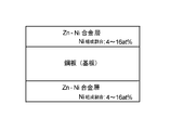
- the steel sheet for producing pipes of the present invention has a zinc-nickel (Zn—Ni) alloy layer on at least the outermost surface of the steel sheet, and the nickel ratio in the Zn—Ni alloy layer is 4
- the Zn—Ni alloy layer can follow the bending process in which the elongation of the bent convex portion generated during the bending process is within 20%, and has excellent corrosion resistance to fuel vapor. It is characterized by.
- the steel sheet for pipe production according to the present invention is characterized in that, in (3), the fuel includes gasoline, bioethanol, light oil, or biodiesel fuel.
- the pipe of the present invention is a pipe having an alloy layer of zinc-nickel (Zn—Ni) at least on the outermost surface of the pipe, and the elongation of the bent convex portion generated during bending is within 20%.
- the Zn—Ni alloy layer can follow a certain bending process and has excellent corrosion resistance to fuel vapor.
- the pipe of the present invention is characterized in that the fuel contains gasoline, bioethanol, light oil, or biodiesel fuel.
- the pipe of the present invention and the steel plate for pipe production have corrosion resistance to fuel vapor, and can suppress rusting even when exposed to fuel vapor such as gasoline, bioethanol, light oil, or biodiesel fuel. Moreover, a plating film follows also in the bending process in the case of a process to a pipe, and the rusting in a process part can be suppressed.
- a low carbon aluminum killed hot rolled coil is usually used as a plating base plate for a steel plate for pipe production. Further, an ultra-low carbon steel having 0.003% by mass or less of carbon, or a coil manufactured from non-aging continuous cast steel by adding niobium or titanium to the steel is also used.
- the steel sheet having the Zn—Ni alloy layer is first subjected to Zn—Ni alloy plating on the steel sheet, but as a pretreatment of the steel sheet, it is usually degreased by electrolysis or immersion in an alkaline solution mainly containing caustic soda, The scale (oxide film) on the surface of the cold rolled steel sheet is removed. After removal, the product is rolled to the product thickness in a cold rolling process.
- the rolling oil adhered by rolling is electrolytically cleaned and then annealed.
- the annealing may be either continuous annealing or box annealing and is not particularly particular. After annealing, the shape is corrected.
- Zn—Ni alloy plating is performed on the steel plate.
- various baths such as a sulfuric acid bath, a chloride bath, and a cyanide bath can be used as a plating bath for obtaining a Zn—Ni alloy plating layer on a steel plate.
- the plating conditions in that case are as follows. That is, a typical watt bath of Ni plating is used as a basic bath, and Zn ions are added.
- Nickel sulfate 20 to 300 g / L
- Nickel chloride 20-50 g / L
- Boric acid 20-50 g / L
- Zinc sulfate 20-300 g / L
- pH 1.5-2.0
- Bath temperature 50-65 ° C
- Current density 5 to 50 A / dm 2
- the boric acid added as a stabilizer may be citric acid.
- the composition ratio of the Zn—Ni alloy layer is Ni: 4 to 16 at% (atomic concentration, hereinafter referred to as atomic concentration), and the remaining Zn. Is preferred.
- the composition ratio of Ni in the Zn—Ni alloy layer is less than 4 at%, sufficient corrosion resistance of the gas phase cannot be obtained.
- the composition ratio of Ni in the Zn—Ni alloy layer exceeds 16 at%, corrosion resistance can be obtained with the flat alloy layer, but due to the hardened alloy layer, the workability is reduced and the alloy layer is cracked during pipe processing. Is generated and the steel is exposed, it is not possible to obtain sufficient corrosion resistance in the gas phase.
- Such adjustment of the composition ratio in the alloy layer can be realized by adjusting the plating bath composition, pH, bath temperature, current density, and the like to suitable ranges.
- the ratio of Ni in the Zn—Ni alloy layer was calculated from the ratio of zinc to nickel by EZ scanning using a Rigaku fluorescent X-ray apparatus (ZSX 100e).
- the thickness of the Zn—Ni alloy layer is 0.5 ⁇ m or more, preferably 3 to 10 ⁇ m, as measured with a Rigaku fluorescent X-ray apparatus (ZSX 100e). If it is less than 0.5 ⁇ m, sufficient corrosion resistance cannot be obtained in the processed portion. When the thickness exceeds 10 ⁇ m, wear powder is generated during processing, resulting in poor productivity.
- Such adjustment of the thickness of the alloy layer can be realized by adjusting the plating bath composition, pH, bath temperature, current density, and the like within suitable ranges.
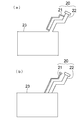
- ⁇ Pipe processing> Using the plated steel sheet with the Zn-Ni alloy layer described above, the shape is corrected with a leveler, slitted to a predetermined outer diameter with a slitter, and then pipe-formed with a molding machine. Pipes are manufactured by seam welding by induction welding. After that, bending and other necessary processing are performed. In addition, after preparing the steel plate which gave the shape correction by a leveler, and the slit by a slitter, you may pipe-pipe. Examples of the pipe include an oil supply pipe for introducing fuel into the tank, a pipe for introducing fuel from the tank to the engine, and a pipe for venting. The fuel supply pipe 20 is attached to the fuel tank 23 as shown in FIG.
- the fuel supply pipe 20 is attached to the fuel tank 23 from the upper part of the fuel tank 23 in an obliquely upward direction.
- a small-diameter pipe portion 22 that branches from the middle of the large-diameter pipe portion 21 through which the fuel passes and is connected to the upper and lower portions of the large-diameter pipe portion 21 is connected to the fuel supply pipe 20.
- the large diameter pipe part 21 is manufactured using the steel plate for pipe manufacture of the present invention. In addition, you may manufacture the small diameter pipe part 22 using the plated steel plate of this invention.
- regulated by this invention is not restricted to a shape as shown to Fig.3 (a),
- Fig.3 (b) For example, as shown in FIG.3 (b), with the large diameter pipe part 21 through which fuel passes, Even if the small-diameter pipe portion 22 is attached to the fuel tank 23 in an independent shape, the corrosion resistance against the fuel vapor is still particularly required, and thus those of these forms are also included.
- Evaluation test pieces were prepared from Zn—Ni alloy steel sheets of various thicknesses, and the corrosion resistance was investigated by immersing them in bioethanol mixed gasoline. Corrosion resistance was confirmed by the presence or absence of rusting. A corrosive solution simulating bioethanol-mixed gasoline was used as a test. Formic acid and acetic acid were added to regular gasoline specified in JIS K2202, and 10% by mass of bioethanol specified in JASO M361 was added to purify the simulated deteriorated gasoline.
- corrosive water in which formic acid, acetic acid and chlorine were added to pure water was prepared, and 10% by mass was added to deteriorated gasoline to obtain a corrosive liquid.
- the corrosive liquid is in a state where the upper layer is divided into degraded gasoline and the lower layer is divided into two layers of corrosive water.
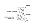
- the evaluation test piece provided with a Zn—Ni alloy layer of each thickness was immersed in this corrosive solution in a sealed container so that it was immersed in a half, and was aged in a 45 ° C. constant temperature bath. Accordingly, as shown in FIG.
- the evaluation test pieces are, from the upper part, the gas phase portion 11 in contact with the fuel vapor (gas phase) of the deteriorated gasoline, the liquid phase portion 12 in contact with the deteriorated gasoline (liquid phase), and corrosion. It will be separated and evaluated in the water phase part 13 in contact with water (water phase). And the corrosion resistance with respect to the fuel vapor
- FIG. 4 shows a method for measuring the elongation of the bent convex portion generated during bending.
- Examples 1 to 6 A cold-rolled and annealed low carbon aluminum killed steel plate having a thickness of 1.0 mm was used as the original plate.
- the components of the steel plate that is the plating original plate are as follows. C: 0.045 mass%, Mn: 0.23 mass%, Si: 0.02 mass%, P: 0.012 mass%, S: 0.009 mass%, Al: 0.063 mass%, N: 0.0036% by mass, balance: Fe and inevitable impurities.
- the steel sheet was subjected to alkaline electrolytic degreasing and acid pickling by sulfuric acid immersion, and then the Zn composition was plated by changing the Ni composition ratio to obtain an alloy-plated steel sheet for pipe production.
- the thickness of the Zn—Ni alloy plating was 3 ⁇ m as measured with a Rigaku fluorescent X-ray apparatus (ZSX 100e).
- Table 1 shows the Ni composition ratio of the Zn—Ni alloy layer.
- the composition ratio in the alloy layer was measured by EZ scan using a Rigaku fluorescent X-ray apparatus (ZSX 100e).
- the fluorescent X-ray apparatus was also used for measuring the thickness of the alloy layer.
- Comparative Examples 1 to 5 The plated steel sheets of Comparative Examples 1 to 5 were obtained in the same manner as in the Examples except that the composition ratio of Ni in the Zn—Ni alloy layer was changed to the values shown in Table 1.
- the steel plate for pipe production according to the present invention suppresses the generation of rust in exposure to fuel vapor such as gasoline, bioethanol, light oil, or biodiesel fuel, and has excellent corrosion resistance to fuel vapor.
- fuel vapor such as gasoline, bioethanol, light oil, or biodiesel fuel
- the deterioration of the fuel itself can be suppressed, and the industrial applicability is extremely high.
Landscapes
- Engineering & Computer Science (AREA)
- Chemical & Material Sciences (AREA)
- Mechanical Engineering (AREA)
- Metallurgy (AREA)
- Electrochemistry (AREA)
- Materials Engineering (AREA)
- Chemical Kinetics & Catalysis (AREA)
- Organic Chemistry (AREA)
- General Engineering & Computer Science (AREA)
- Cooling, Air Intake And Gas Exhaust, And Fuel Tank Arrangements In Propulsion Units (AREA)
- Electroplating Methods And Accessories (AREA)
- Fuel-Injection Apparatus (AREA)
- Bending Of Plates, Rods, And Pipes (AREA)
- Rigid Pipes And Flexible Pipes (AREA)
- Other Surface Treatments For Metallic Materials (AREA)
Abstract
Description
このように、吸湿状態とガソリンの劣化が発生した場合、エタノールは水とガソリンの両方に混合できるため、ガソリン内部に水と有機酸が含まれた状態になり、さらにガソリン表面から水と有機酸の混合物が気化することがある。そのとき、通常は腐食性の殆ど無いガソリン蒸気にしか接触しないパイプの内面が、強い腐食環境下に置かれる場合が想定される。
よって、バイオエタノール混合ガソリンの雰囲気下に置かれるパイプには、燃料蒸気による腐食環境をも想定した耐食性が求められる。
従来、自動車用燃料パイプ用途として、冷延のままや銅めっき鋼板が広く使われている。また、原板にステンレス鋼を用いたパイプやSn-Znめっきを施したパイプが提案されている。
例えば、特許文献1には、燃料容器の内面の燃料耐食性、外面の塗装後耐食性などを向上させることを目的として、亜鉛系めっき鋼板の上に、後処理皮膜を付着量にして0.1~2.0g/m2付着後、20℃/s以上の速度で、めっき表面側から加熱昇温して後処理皮膜の乾燥条件を制御して乾燥させた亜鉛系燃料容器用鋼板が記載されている。
つまり、タンクへのプレス加工性およびプレス加工後の燃料耐食性であり、給油管は実際の使用環境としては自動車用燃料に直接暴露されることより、揮発性の高い自動車燃料の蒸気に暴露されるケースの方が圧倒的に多い。
また、国際的に化石燃料の枯渇化が深刻化しており、バイオエタノールやバイオディーゼル燃料などの普及が広まっている。
このように、従来の自動車燃料であるガソリンに加え、バイオエタノールやバイオディーゼル燃料及びその蒸気の両方に対して十分な特性を有するめっき鋼板は安全性上問題となっていた。
また、めっき鋼板をパイプ材料として使用する場合、搭載上の問題から、造管後曲げ部を多く有することになり、めっき皮膜には高い耐食性と共に曲げ加工に対する追随性が要求されている。
また、本発明の他の目的は、その鋼板を用いたパイプ及びパイプの製造方法を提供することである。
(2)本発明の曲げ部を有するパイプの製造方法は、前記(1)において、前記燃料が、ガソリン、バイオエタノール、軽油、又はバイオディーゼル燃料を含むことを特徴とする。
(3)本発明のパイプ製造用鋼板は、鋼板の少なくともパイプ内面となる面の最表面に亜鉛-ニッケル(Zn-Ni)の合金層を有し、前記Zn-Ni合金層におけるニッケル割合が4~16at%であり、曲げ加工の際に生じる折り曲げ凸部の伸びが20%以内である曲げ加工に前記Zn-Ni合金層が追随可能であり、かつ、燃料蒸気への耐食性に優れていることを特徴とする。
(4)本発明のパイプ製造用鋼板は、前記(3)において、前記燃料が、ガソリン、バイオエタノール、軽油、又はバイオディーゼル燃料を含むことを特徴とする。
(5)本発明のパイプは、少なくともパイプ内面の最表面に亜鉛-ニッケル(Zn-Ni)の合金層を有するパイプであって、曲げ加工の際に生じる折り曲げ凸部の伸びが20%以内である曲げ加工に前記Zn-Ni合金層が追随可能であり、かつ、燃料蒸気への耐食性に優れていることを特徴とする。
(6)本発明のパイプは、前記燃料が、ガソリン、バイオエタノール、軽油、又は、バイオディーゼル燃料を含むことを特徴とする。
<鋼板>
パイプ製造用鋼板のめっき原板としては、通常低炭素アルミキルド熱延コイルが用いられる。また、炭素0.003質量%以下の極低炭素鋼、または更にこれにニオブ、チタンを添加し非時効連続鋳造鋼から製造されたコイルも用いられる。
Zn-Ni合金層を有する鋼板は、本実施形態ではまず鋼板にZn-Ni合金めっきを施すが、鋼板の前処理としては、通常苛性ソーダを主剤としたアルカリ液に電解または浸漬による脱脂を行い、冷延鋼板表面のスケール(酸化膜)を除去する。除去後、冷間圧延工程にて製品厚みまで圧延する。
圧延で付着した圧延油を電解洗浄した後、焼鈍する。焼鈍は、連続焼鈍あるいは箱型焼鈍のどちらでもよく特にこだわらない。焼鈍した後、形状修正する。
次に、鋼板上に、Zn-Ni合金めっきを施す。本発明において、鋼板上にZn-Ni合金めっき層を得るためのめっき浴としては、硫酸浴、塩化物浴、シアン化物浴など、種々の浴を用いることができる。その場合のめっき条件は以下のとおりである。すなわち、Niめっきの代表的なワット浴を基本浴として用い、Znイオンを添加することにより実施する。
めっき浴組成
硫酸ニッケル:20~300g/L、
塩化ニッケル:20~50g/L、
ホウ酸:20~50g/L、
硫酸亜鉛:20~300g/L、
pH:1.5~2.0、
浴温:50~65℃、
電流密度:5~50A/dm2、
とする。なお、安定剤として添加するホウ酸はクエン酸でもよい。
Zn-Ni合金層中のNiの組成割合が4at%未満の場合、気相部の十分な耐食性を得ることはできない。
また、Zn-Ni合金層のNiの組成割合が16at%を超える場合、平板での合金層では耐食性は得られるが、合金層の硬質化により、加工性が低下しパイプ加工時に合金層に割れが発生し地鉄が露出するため、気相部の十分な耐食性を得ることはできない。
このような合金層中における組成割合の調整は、前記めっき浴組成、pH、浴温、電流密度等を好適な範囲に調整することによって実現できる。
なお、Zn-Ni合金層中におけるNiの割合は、リガク製蛍光X線装置(ZSX 100e)を使用し、EZスキャンにより亜鉛とニッケル比率から算出した。
Zn-Ni合金層の厚みは、リガク製蛍光X線装置(ZSX 100e)により測定し、0.5μm以上、好ましくは3~10μmである。0.5μm未満では加工部分において十分な耐食性が得られない。10μmを超えた場合、加工の際に磨耗粉が生じ、生産性が悪くなる。このような合金層の厚みの調整は、前記めっき浴組成、pH、浴温、電流密度等を好適な範囲に調整することによって実現できる。
上記Zn-Ni合金層を形成しためっき鋼板を使用し、レベラーにより形状修正し、スリッターで所定の外寸径にスリットした後、成形機によりパイプ状に造管し、長手方向の端面同士を高周波誘導溶接によりシーム溶接することによりパイプを製造する。その後、曲げ加工、その他必要な加工を施す。
なお、レベラーによる形状修正、スリッターによるスリットを施した鋼板を準備した後、パイプを造管してもよい。
パイプとしては、燃料をタンクに導入する給油パイプやタンクからエンジンに燃料を導入するパイプや、通気を行うパイプが挙げられる。
給油パイプ20の燃料タンク23への取り付けは、図3(a)に示すように、給油パイプ20の燃料タンク23への取り付けは、燃料タンク23の上部から斜め上方向へ延出させた。
また、給油パイプ20には、燃料が通過する太径パイプ部21の途中から分岐をさせて、太径パイプ部21の上部と下部とを通気する細径パイプ部22を接続した。
太径パイプ部21を本発明のパイプ製造用鋼板を用いて製造する。なお、細径パイプ部22も本発明のめっき鋼板を用いて製造してもよい。
なお、本発明で規定する給油パイプ20は、図3(a)に示すような形状に限らず、例えば、図3(b)に示すように、燃料が通過する太径パイプ部21とは、独立した形状で細径パイプ部22が燃料タンク23に取り付けられているものであっても、燃料蒸気に対する耐食性が特に要求されることに変わりはないので、これらの形態のものも含む。
種々の厚みのZn-Ni合金鋼板から評価試験片を作製し、バイオエタノール混合ガソリンに浸漬させることにより耐食性を調査した。耐食性は発錆の有無で確認した。
バイオエタノール混合ガソリンを試験的に模した腐食液を使用した。
JIS K2202に規定されているレギュラーガソリンに、ギ酸、酢酸を添加し、JASO M361に規定されているバイオエタノールを10質量%添加し、模擬的な劣化ガソリンを精製した。
更に腐食性を高めることを目的に、純水に、ギ酸、酢酸、塩素を添加した腐食水を作製し、劣化ガソリンに10質量%添加して腐食液とした。腐食液は、上層が劣化ガソリン、下層が腐食水の2層に分かれた状態となる。この腐食液に各厚みのZn-Ni合金層を設けた評価試験片が半分浸漬するように密閉容器中に配置し、45℃の恒温槽にて経時した。
これにより、図2に示すように、評価試験片は、上部より、劣化ガソリンの燃料蒸気(気相)と接触した気相部11、劣化ガソリン(液相)と接触した液相部12,腐食水(水相)と接触した水相部13に分離されて評価されることになる。そして、評価試験片の気相部11の腐食を調査することにより、評価試験片の燃料蒸気に対する耐食性を評価した。
Zn-Ni合金層を設けた評価試験片はパイプの曲げ加工を想定し、合金層を設けた面を凸部(図2で山部)として90°折り曲げを行ったものを使用した。90°折り曲げの谷部の半径、すなわち、金型の肩部半径は2.0mmとし、加工された山部の発錆を評価した。
多くの実験結果から、Zn-Ni合金層のNi割合が4~16at%において90°折り曲げ部山部の気相部に対する発錆が抑制された。
Zn-Ni合金層内のNi割合が4%未満では、90°の折り曲げ加工において合金層は追随するが、Znが多いために十分な耐食性を得る事は出来ない。
また、Zn-Ni合金層内のNi割合が16at%を超えると、合金層が硬質化するため、90°折り曲げ加工により合金層にクラックが入り、そこから腐食液が浸透するため、十分な耐食性を得る事は出来ない。
よって、多くの実験結果から、Zn-Ni合金層のNi組成割合を、4~16at%の範囲とした場合に、評価試験片の気相部での発錆が抑制されることが分かった。
また、図4に、曲げ加工の際に生じる折り曲げ凸部の伸びの測定方法を示す。すなわち、板の曲げ加工の場合においては、図4(a)に示すように、板厚tと肩部半径rから求められる。ここで、rは板の曲げ加工に用いる金型の肩部半径であり、折り曲げ凸部の伸び(%)は図中の四角で囲む計算式によって求められる。
また、パイプ加工の場合においては、図4(b)に示すように、パイプ径Tと金型の肩部半径Rから求められる。ここで、Rはパイプの曲げ加工に用いる金型の肩部半径であり、折り曲げ凸部の伸び(%)は図中の四角で囲む計算式によって求められる。例えば、T=30mmのパイプをR=60mmで曲げ加工したときに伸びは20%となり、板厚1mmの90°折り曲げ加工の伸びと同じになる。
<実施例1~6>
板厚1.0mmの、冷延、焼鈍済みの低炭素アルミキルド鋼板を原板とした。
めっき原板である鋼板の成分は以下のとおりである。
C:0.045質量%、Mn:0.23質量%、Si:0.02質量%、P:0.012質量%、S:0.009質量%、Al:0.063質量%、N:0.0036質量%、残部:Fe及び不可避的不純物である。この鋼板を、アルカリ電解脱脂、硫酸浸漬の酸洗を行った後、Ni組成割合を変えてZn-Ni合金めっきを行いパイプ製造用合金めっき鋼板とした。
なお、Zn-Ni合金めっきの厚みは、リガク製蛍光X線装置(ZSX 100e)により測定し、3μmとした。
Zn-Ni合金層のNi組成割合を、表1に示す。なお、合金層中の組成割合はリガク製蛍光X線装置(ZSX 100e)を使用し、EZスキャンにより測定した。合金層の厚みの測定にも前記蛍光X線装置を用いた。
Zn-Ni合金層中のNiの組成割合を、表1に示す値に変更した以外は、実施例と同様にして、比較例1~5のめっき鋼板を得た。

実施例、比較例の各合金層を有する鋼板から評価試験片を作製し、45℃の恒温槽にて2000時間経時させた後に、各評価試験片の外観を観察し、気相部、液相部においてそれぞれ赤錆発生を調査した。この結果を表1の「気相部の発錆発生結果」、「液相部の発錆発生結果」の欄に示す。
液相部、気相部の両方において赤錆の発生を抑制した。
また、めっき外観も良好であり、燃料蒸気への耐食性を備えたパイプ製造用鋼板として優れていた。
一方、比較例1~5のめっき鋼板は、液相部においては錆の発生が見られなかったが、
気相部においては赤錆が発生し、耐食性が要求されるパイプ製造用鋼板として実用性に乏しい。
12:液相部
13:水相部
20:給油パイプ
21:太径パイプ部
22:細径パイプ部
23:燃料タンク
Claims (6)
- パイプの製造方法であって、少なくとも一方の表面にニッケル割合が4~16at%である亜鉛-ニッケル(Zn-Ni)の合金層を有することを特徴とするパイプ製造用鋼板を準備する工程と、前記パイプ製造用鋼板を前記Zn-Ni合金層を内面とし筒状に加工する工程と、曲げ加工の際に生じる折り曲げ凸部の伸びが20%以内である曲げ加工を施す工程と、を有する燃料蒸気への耐食性に優れた曲げ部を有するパイプの製造方法。
- 前記燃料が、ガソリン、バイオエタノール、軽油、又はバイオディーゼル燃料を含むことを特徴とする請求項1に記載の燃料蒸気への耐食性に優れた曲げ部を有するパイプの製造方法。
- 鋼板の少なくともパイプ内面となる面の最表面に亜鉛-ニッケル(Zn-Ni)の合金層を有し、前記Zn-Ni合金層におけるニッケル割合が4~16at%であり、曲げ加工の際に生じる折り曲げ凸部の伸びが20%以内である曲げ加工に前記Zn-Ni合金層が追随可能であり、かつ、燃料蒸気への耐食性に優れたことを特徴とするパイプ製造用鋼板。
- 前記燃料が、ガソリン、バイオエタノール、軽油、又はバイオディーゼル燃料を含む請求項3に記載の燃料蒸気の存在下で使用しても燃料蒸気への耐食性に優れたことを特徴とするパイプ製造用鋼板。
- 少なくともパイプ内面の最表面に亜鉛-ニッケル(Zn-Ni)の合金層を有するパイプであって、曲げ加工の際に生じる折り曲げ凸部の伸びが20%以内である曲げ加工に前記Zn-Ni合金層が追随可能であり、かつ、燃料蒸気への耐食性に優れたことを特徴とするパイプ。
- 前記燃料が、ガソリン、バイオエタノール、軽油、又は、バイオディーゼル燃料を含む請求項5に記載の燃料蒸気の存在下で使用しても燃料蒸気への耐食性に優れたことを特徴とするパイプ。
Priority Applications (3)
| Application Number | Priority Date | Filing Date | Title |
|---|---|---|---|
| JP2012527607A JP5867927B2 (ja) | 2010-08-06 | 2011-08-04 | 燃料蒸気への耐食性に優れたパイプ製造用鋼板、それを用いたパイプ及びパイプの製造方法 |
| US13/814,502 US9700928B2 (en) | 2010-08-06 | 2011-08-04 | Steel plate for producing pipe highly resistant to fuel vapor corrosion, pipe using same and method for producing pipe |
| CN201180037407.6A CN103037996B (zh) | 2010-08-06 | 2011-08-04 | 对燃料蒸气的抗蚀性优异的制管用钢板、使用该钢板的管及管的制造方法 |
Applications Claiming Priority (2)
| Application Number | Priority Date | Filing Date | Title |
|---|---|---|---|
| JP2010176960 | 2010-08-06 | ||
| JP2010-176960 | 2010-08-06 |
Publications (1)
| Publication Number | Publication Date |
|---|---|
| WO2012017674A1 true WO2012017674A1 (ja) | 2012-02-09 |
Family
ID=45559193
Family Applications (1)
| Application Number | Title | Priority Date | Filing Date |
|---|---|---|---|
| PCT/JP2011/004447 Ceased WO2012017674A1 (ja) | 2010-08-06 | 2011-08-04 | 燃料蒸気への耐食性に優れたパイプ製造用鋼板、それを用いたパイプ及びパイプの製造方法 |
Country Status (4)
| Country | Link |
|---|---|
| US (1) | US9700928B2 (ja) |
| JP (1) | JP5867927B2 (ja) |
| CN (1) | CN103037996B (ja) |
| WO (1) | WO2012017674A1 (ja) |
Cited By (1)
| Publication number | Priority date | Publication date | Assignee | Title |
|---|---|---|---|---|
| EP2871263A4 (en) * | 2012-07-04 | 2016-03-02 | Usui Kokusai Sangyo Kk | TUBE WITH A HEAT-RESISTANT CORROSION-RESISTANT PLATING LAYER WITH EXCELLENT PROCESSABILITY |
Families Citing this family (1)
| Publication number | Priority date | Publication date | Assignee | Title |
|---|---|---|---|---|
| CN108129936A (zh) * | 2018-01-03 | 2018-06-08 | 中山市大涌镇生产力促进中心 | 一种木材电镀染色方法 |
Citations (4)
| Publication number | Priority date | Publication date | Assignee | Title |
|---|---|---|---|---|
| JPH059786A (ja) * | 1990-11-02 | 1993-01-19 | Usui Internatl Ind Co Ltd | 内面の耐食性に優れた溶接管及びその製造方法 |
| JPH09324282A (ja) * | 1996-06-06 | 1997-12-16 | Sumitomo Metal Ind Ltd | 加工後耐食性に優れた表面処理鋼板 |
| JP2002242779A (ja) * | 2000-12-04 | 2002-08-28 | Futaba Industrial Co Ltd | フューエルインレットの製造方法 |
| JP2009113066A (ja) * | 2007-11-05 | 2009-05-28 | Nittetsu Steel Pipe Co Ltd | 給油管用電縫鋼管 |
Family Cites Families (27)
| Publication number | Priority date | Publication date | Assignee | Title |
|---|---|---|---|---|
| JPS6057518B2 (ja) * | 1981-07-14 | 1985-12-16 | 株式会社神戸製鋼所 | 耐蝕性と耐水密着性に優れた表面処理鋼材 |
| US4885215A (en) * | 1986-10-01 | 1989-12-05 | Kawasaki Steel Corp. | Zn-coated stainless steel welded pipe |
| JP2631648B2 (ja) * | 1986-10-23 | 1997-07-16 | 臼井国際産業株式会社 | 耐食性並びに流体への酸化防止被膜を有する電縫鋼管およびその製造方法 |
| GB2222785B (en) * | 1988-09-17 | 1992-02-12 | Usui Kokusai Sangyo Kk | Multi-layered pipe coating |
| JP2848888B2 (ja) * | 1990-01-10 | 1999-01-20 | 臼井国際産業株式会社 | 耐食性一重巻鋼管及びその製造方法 |
| DE4136038C2 (de) * | 1990-11-02 | 1994-06-16 | Usui Kokusai Sangyo Kk | Geschweißtes Stahlrohr mit hoher Korrosionsbeständigkeit der Innenoberfläche sowie Verfahren zu seiner Herstellung |
| JPH05106058A (ja) * | 1991-10-18 | 1993-04-27 | Kawasaki Steel Corp | 燃料容器用高耐食性表面処理鋼板 |
| JP3176405B2 (ja) * | 1991-12-02 | 2001-06-18 | 臼井国際産業株式会社 | 内面の耐食性に優れた溶接管及びその製造方法 |
| BE1005554A3 (fr) * | 1991-12-10 | 1993-10-26 | Bundy Internat Ltd | Procede de fabrication d'un tube a paroi multiple. |
| JP3403263B2 (ja) * | 1994-11-14 | 2003-05-06 | 臼井国際産業株式会社 | 加工性・耐食性の均一性に優れた耐熱・耐食性めっき鋼材 |
| JP3445858B2 (ja) * | 1994-12-29 | 2003-09-08 | 臼井国際産業株式会社 | 保護被覆層を有する自動車用金属配管 |
| JPH08225984A (ja) * | 1995-02-21 | 1996-09-03 | Kawasaki Steel Corp | めっき外観、めっき密着性および耐食性に優れたZn−Ni合金めっき鋼板の製造方法 |
| JP3885910B2 (ja) * | 1997-10-09 | 2007-02-28 | 臼井国際産業株式会社 | フューエル・デリバリ・パイプ及びその製造方法 |
| JP3497413B2 (ja) * | 1998-07-30 | 2004-02-16 | 新日本製鐵株式会社 | 耐食性、加工性および溶接性に優れた燃料容器用表面処理鋼板 |
| US6276400B1 (en) * | 1999-06-08 | 2001-08-21 | Itt Manufacturing Enterprises, Inc. | Corrosion resistant powder coated metal tube and process for making the same |
| US6325108B1 (en) * | 1999-06-21 | 2001-12-04 | David S. Bettinger | Prestressed composite cryogenic piping |
| US6976510B2 (en) * | 2000-01-19 | 2005-12-20 | Itt Manufacturing Enterprises, Inc. | Corrosion resistant metal tube and process for making the same |
| JP3831340B2 (ja) * | 2000-08-11 | 2006-10-11 | アイティーティー・マニュファクチャリング・エンタープライジズ・インコーポレーテッド | 金属管に接合されたプラスチック層の機械的除去装置 |
| JP4014907B2 (ja) * | 2002-03-27 | 2007-11-28 | 日新製鋼株式会社 | 耐食性に優れたステンレス鋼製の自動車用燃料タンクおよび給油管 |
| JP2004052093A (ja) * | 2002-07-24 | 2004-02-19 | Sanoh Industrial Co Ltd | 多層めっき自動車燃料配管部品 |
| US20050031894A1 (en) * | 2003-08-06 | 2005-02-10 | Klaus-Peter Klos | Multilayer coated corrosion resistant article and method of production thereof |
| US20070261752A1 (en) * | 2006-04-13 | 2007-11-15 | Stant Manufacturing Inc. | Multiple-layer fluid fuel apparatus |
| US8091588B2 (en) * | 2008-05-30 | 2012-01-10 | Fluid Routing Solutions, Inc. | Metallic tubular structure |
| JP5392717B2 (ja) * | 2009-09-18 | 2014-01-22 | 東洋鋼鈑株式会社 | 給油パイプ |
| EP2479317B1 (en) * | 2009-09-18 | 2019-04-24 | Toyo Kohan Co., Ltd. | Fuel supply pipe |
| JP5773515B2 (ja) * | 2010-07-23 | 2015-09-02 | 臼井国際産業株式会社 | スチール製の燃料圧送配管 |
| JP5690306B2 (ja) * | 2012-06-08 | 2015-03-25 | ディップソール株式会社 | 塗装ステンレス鋼部材 |
-
2011
- 2011-08-04 US US13/814,502 patent/US9700928B2/en active Active
- 2011-08-04 JP JP2012527607A patent/JP5867927B2/ja active Active
- 2011-08-04 WO PCT/JP2011/004447 patent/WO2012017674A1/ja not_active Ceased
- 2011-08-04 CN CN201180037407.6A patent/CN103037996B/zh active Active
Patent Citations (4)
| Publication number | Priority date | Publication date | Assignee | Title |
|---|---|---|---|---|
| JPH059786A (ja) * | 1990-11-02 | 1993-01-19 | Usui Internatl Ind Co Ltd | 内面の耐食性に優れた溶接管及びその製造方法 |
| JPH09324282A (ja) * | 1996-06-06 | 1997-12-16 | Sumitomo Metal Ind Ltd | 加工後耐食性に優れた表面処理鋼板 |
| JP2002242779A (ja) * | 2000-12-04 | 2002-08-28 | Futaba Industrial Co Ltd | フューエルインレットの製造方法 |
| JP2009113066A (ja) * | 2007-11-05 | 2009-05-28 | Nittetsu Steel Pipe Co Ltd | 給油管用電縫鋼管 |
Cited By (1)
| Publication number | Priority date | Publication date | Assignee | Title |
|---|---|---|---|---|
| EP2871263A4 (en) * | 2012-07-04 | 2016-03-02 | Usui Kokusai Sangyo Kk | TUBE WITH A HEAT-RESISTANT CORROSION-RESISTANT PLATING LAYER WITH EXCELLENT PROCESSABILITY |
Also Published As
| Publication number | Publication date |
|---|---|
| US9700928B2 (en) | 2017-07-11 |
| CN103037996A (zh) | 2013-04-10 |
| US20130199657A1 (en) | 2013-08-08 |
| JP5867927B2 (ja) | 2016-02-24 |
| JPWO2012017674A1 (ja) | 2013-10-03 |
| CN103037996B (zh) | 2016-05-18 |
Similar Documents
| Publication | Publication Date | Title |
|---|---|---|
| JP5649076B2 (ja) | 燃料蒸気に対する耐食性を有する給油パイプ | |
| WO2011033775A1 (ja) | 燃料蒸気に対する耐食性を有するパイプ製造用表面処理鋼板、その鋼板を用いたパイプおよび給油パイプ | |
| JP6400140B2 (ja) | 表面処理鋼板の製造方法、および電池缶の製造方法 | |
| US8993118B2 (en) | Steel sheet for container excellent in corrosion resistance | |
| KR20240116478A (ko) | V, Ce, La, Mn을 포함하는 아연-알루미늄-마그네슘 합금 도금층 강재 및 그의 제조방법 | |
| JP5392717B2 (ja) | 給油パイプ | |
| JP6103139B2 (ja) | 化成処理鋼板及び化成処理鋼板の製造方法 | |
| JP5867927B2 (ja) | 燃料蒸気への耐食性に優れたパイプ製造用鋼板、それを用いたパイプ及びパイプの製造方法 | |
| KR20240116477A (ko) | V, b를 포함하는 아연-알루미늄-마그네슘 합금 도금층 강재 및 그의 제조방법 | |
| JP5392718B2 (ja) | 給油パイプ | |
| JP5408777B2 (ja) | 給油パイプ | |
| WO2011135787A1 (ja) | 燃料蒸気に対する耐食性を有するパイプ製造用めっき鋼板、そのめっき鋼板を用いたパイプ及び給油パイプ | |
| JP6354915B1 (ja) | 自動二輪車燃料タンク用鋼板および燃料タンク部材 | |
| JP6066030B2 (ja) | 容器用鋼板及び容器用鋼板の製造方法 | |
| WO2017163298A1 (ja) | 化成処理鋼板及び化成処理鋼板の製造方法 | |
| JP2015196882A (ja) | 錫亜鉛めっき鋼板とその製造方法 | |
| WO2017163299A1 (ja) | 化成処理鋼板及び化成処理鋼板の製造方法 | |
| JP2016211024A (ja) | 容器用鋼板及び容器用鋼板の製造方法 |
Legal Events
| Date | Code | Title | Description |
|---|---|---|---|
| WWE | Wipo information: entry into national phase |
Ref document number: 201180037407.6 Country of ref document: CN |
|
| 121 | Ep: the epo has been informed by wipo that ep was designated in this application |
Ref document number: 11814309 Country of ref document: EP Kind code of ref document: A1 |
|
| WWE | Wipo information: entry into national phase |
Ref document number: 2012527607 Country of ref document: JP |
|
| NENP | Non-entry into the national phase |
Ref country code: DE |
|
| WWE | Wipo information: entry into national phase |
Ref document number: 13814502 Country of ref document: US |
|
| 122 | Ep: pct application non-entry in european phase |
Ref document number: 11814309 Country of ref document: EP Kind code of ref document: A1 |