WO2012014947A1 - 衛生洗浄装置 - Google Patents
衛生洗浄装置 Download PDFInfo
- Publication number
- WO2012014947A1 WO2012014947A1 PCT/JP2011/067148 JP2011067148W WO2012014947A1 WO 2012014947 A1 WO2012014947 A1 WO 2012014947A1 JP 2011067148 W JP2011067148 W JP 2011067148W WO 2012014947 A1 WO2012014947 A1 WO 2012014947A1
- Authority
- WO
- WIPO (PCT)
- Prior art keywords
- water
- electrolytic cell
- flow path
- strainer
- nozzle
- Prior art date
Links
Images


Classifications
-
- E—FIXED CONSTRUCTIONS
- E03—WATER SUPPLY; SEWERAGE
- E03D—WATER-CLOSETS OR URINALS WITH FLUSHING DEVICES; FLUSHING VALVES THEREFOR
- E03D9/00—Sanitary or other accessories for lavatories ; Devices for cleaning or disinfecting the toilet room or the toilet bowl; Devices for eliminating smells
- E03D9/08—Devices in the bowl producing upwardly-directed sprays; Modifications of the bowl for use with such devices ; Bidets; Combinations of bowls with urinals or bidets; Hot-air or other devices mounted in or on the bowl, urinal or bidet for cleaning or disinfecting
-
- E—FIXED CONSTRUCTIONS
- E03—WATER SUPPLY; SEWERAGE
- E03D—WATER-CLOSETS OR URINALS WITH FLUSHING DEVICES; FLUSHING VALVES THEREFOR
- E03D9/00—Sanitary or other accessories for lavatories ; Devices for cleaning or disinfecting the toilet room or the toilet bowl; Devices for eliminating smells
- E03D9/005—Devices adding disinfecting or deodorising agents to the bowl
Definitions
- the aspect of the present invention generally relates to a sanitary washing apparatus, and more particularly, to a sanitary washing apparatus that cleans a user's “butt” or the like seated on a Western-style sitting toilet with water.
- the cleaning nozzle that cleans the body of the user sitting on the toilet seat, such as the “tail”, is exposed (advanced) at least partially from the casing to which the functional parts such as the cleaning nozzle and hot water tank are attached. Inject washing water into Therefore, there is a possibility that dirty water and filth may adhere to the cleaning nozzle.
- bacteria may propagate to the cleaning nozzle over time. More specifically, for example, methylobacterium called pink slime generated on the bowl surface of the toilet bowl or bacteria such as black mold may adhere to the washing nozzle and the bacteria may propagate on the washing nozzle.
- bacteria are propagated and, for example, bacteria called biofilms and their secretions (slimming, black stains) are formed, the normal nozzle cleaning as described above removes the biofilms. It becomes difficult.
- Patent Document 1 there is a local cleaning device incorporating an electrolytic cell as a nozzle cleaning generator (Patent Document 1).
- Patent Document 1 when tap water is used as cleaning water, chlorine contained therein can be chemically changed into hypochlorous acid by electrolysis, and can be cleaned as an acidic chemical solution. . For this reason, it is possible to perform effective cleaning particularly against dirt due to ammonia or the like.
- the electrolytic cell is provided in a portion closer to the nozzle. Therefore, there is a local cleaning device in which an electrolytic cell is provided in a flow path downstream of the hot water tank (Patent Document 2).
- Patent Document 2 hot water in the electrolytic cell is electrolyzed to generate electrolytic water.
- cleaning means injects warm water as washing water with respect to a buttocks washing nozzle and a bidet washing nozzle.
- the local cleaning device described in Patent Document 2 reverses the polarity of the voltage applied to the electrodes in order to remove the scale.
- the generated scale is peeled off from the surface of the electrode by polarity reversal.
- the flow path may be blocked by the scale peeled off from the electrode.
- the present invention has been made on the basis of recognition of such a problem, and an object thereof is to provide a sanitary washing apparatus capable of suppressing clogging due to a scale of a flow path.
- the nozzle has a water discharge port, jets water from the water discharge port, and cleans the user's body, and a flow path that guides water supplied from a water supply source to the water discharge port.
- An electrolytic cell provided in the middle of the flow path, capable of generating sterilizing water, nozzle cleaning means for cleaning or sterilizing the nozzle with the sterilizing water generated by the electrolytic cell, and downstream from the electrolytic cell.
- a sanitary washing device characterized in that a contracted flow portion having a channel cross-sectional area smaller than the upstream side is formed, and a strainer is further arranged on the downstream side.
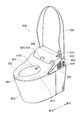
- FIG. 1 is a schematic perspective view showing a toilet apparatus provided with a sanitary washing device according to an embodiment of the present invention.
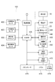
- FIG. 2 is a block diagram showing a main configuration of the sanitary washing device according to the present embodiment.
- FIG. 3 is a schematic perspective view illustrating a specific example of the nozzle unit of the present embodiment.
- FIG. 4 is a conceptual schematic diagram showing an outline of the operation of the sanitary washing device according to this embodiment and the state of the flow path.
- FIG. 5 is a schematic plan view for explaining a scale generated in the electrolytic cell unit of the present embodiment.
- FIG. 6 is a graph showing the change in the dissolved amount of calcium carbonate and carbonate ions based on the change in pH.
- FIG. 1 is a schematic perspective view showing a toilet apparatus provided with a sanitary washing device according to an embodiment of the present invention.
- FIG. 2 is a block diagram showing a main configuration of the sanitary washing device according to the present embodiment.
- FIG. 3 is a schematic perspective view
- FIG. 7 is a schematic plan view for explaining a scale generated in the heat exchanger unit of the present embodiment.
- FIG. 8 is a graph showing changes in the dissolved amount of calcium carbonate based on temperature changes.
- FIG. 9 is a schematic plan view illustrating the strainer that captures the scale according to the embodiment of the present embodiment.
- FIG. 10 is a partially enlarged schematic view of FIG.
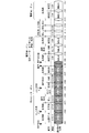
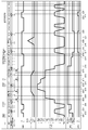
- FIG. 11 is a timing chart illustrating a specific example of the operation of the sanitary washing device according to this embodiment.
- a nozzle that has a water discharge port, jets water from the water discharge port to wash a user's body, a flow path that guides water supplied from a water supply source to the water discharge port, An electrolytic cell provided in the middle of the path and capable of generating sterilizing water, nozzle cleaning means for cleaning or sterilizing the nozzle with the sterilizing water generated by the electrolytic cell, and a flow path disconnection downstream from the electrolytic cell
- the sanitary washing apparatus is characterized in that a constricted flow portion having an area smaller than that of the upstream side is formed, and a strainer is further arranged on the downstream side.
- the strainer not only captures the scale discharged from the electrolytic cell, but also reduces the flow into the area of unstable electrolytic water discharged from the electrolytic cell where the scale may precipitate.
- the flow turbulence generated by this constricted flow part intentionally induces and captures scale deposition and scale growth, so that clogging of the flow path by the scale downstream from the strainer is prevented. Can be suppressed.
- the pH (pH) on the cathode side is increased by electrolyzing tap water, and a scale is likely to be formed on the electrode surface. It is in a high state.
- the electrolyzed water discharged from the electrolytic cell flows down the flow path, but in the basin just discharged from the electrolytic cell, the pH state is unstable and high, so there is a risk of scale precipitation and it is generated in the electrolytic cell. It is speculated that small scale debris may grow. Precipitation and growth of such scale are presumed to have occurred due to disturbance of the flow of electrolyzed water flowing out from the electrolytic cell. Therefore, it is possible to reduce the diameter of the flow path, intentionally deposit scale at the reduced diameter portion, capture the scale with a strainer, and suppress unexpected scale deposition and growth downstream of the strainer. Become.
- 2nd invention is mounted in the toilet bowl upper part, has a spout, the nozzle which spouts water toward the bowl surface of the said toilet from the said spout, and the water supplied from a water supply source to the said spout
- the sanitary washing apparatus is characterized in that a contracted portion having a channel cross-sectional area smaller than the upstream side is formed on the downstream side from the tank, and a strainer is further arranged on the downstream side.
- the strainer not only captures the scale discharged from the electrolytic cell, but also reduces the flow into the area of unstable electrolytic water discharged from the electrolytic cell where the scale may precipitate. Since the flow turbulence generated by this constricted part intentionally promotes and captures scale precipitation and scale growth, the flow path is blocked by the scale downstream from the strainer. Can be suppressed.
- the pH on the cathode side is increased by electrolyzing tap water, and a scale is likely to be formed on the electrode surface, but the pH is also high in a water region slightly away from the electrode surface. It has become.
- the electrolyzed water discharged from the electrolytic cell flows down the flow path, but the basin just discharged from the electrolytic cell is unstable and high in pH, so there is a risk of precipitation of scale and it is generated in the electrolytic cell. It is speculated that small scale fragments may grow. Precipitation and growth of such scale are presumed to have occurred due to disturbance in the flow of electrolyzed water flowing out from the electrolytic cell. Therefore, it is possible to reduce the diameter of the flow path, intentionally deposit scale at the reduced diameter portion, capture the scale with a strainer, and suppress unexpected scale deposition and growth downstream of the strainer. Become.
- the contracted portion is formed at a predetermined interval from the outlet portion of the electrolytic cell.
- the contracted portion is formed at a predetermined interval from the outlet portion of the electrolytic cell.
- the outlet portion of the electrolytic cell is configured with a relatively narrow flow path, when the constricted flow portion is formed in the vicinity thereof, the deposited and grown scale is deposited near the outlet, Since there is a possibility of causing the outlet portion to be blocked, the deposited and grown scale can be effectively captured by the strainer by keeping a predetermined interval from the outlet portion, and the blocking of the flow path can be suppressed.
- the fifth aspect of the present invention is the sanitary washing apparatus according to the first aspect, wherein the outlet-side flow path of the electrolytic cell is an outlet portion having a larger diameter than the upstream side.
- the flow path on the outlet side of the electrolytic cell is an outlet portion having a larger diameter than the upstream side.
- the seventh invention is the sanitary washing device according to the first invention, wherein the strainer is detachably provided.
- An eighth invention is the sanitary washing device according to the second invention, wherein the strainer is detachably provided.
- the strainer can be attached and detached, the flow rate at the time of body washing of the user can be reduced by removing the scale captured periodically and reducing the flow resistance in the strainer. It can suppress impairing a feeling.
- the ninth invention is the sanitary washing apparatus according to the first invention, wherein the strainer is formed of a material having a low surface energy.
- the tenth invention is the sanitary washing apparatus according to the second invention, wherein the strainer is made of a material having a low surface energy.
- the scale particles captured by the strainer are less likely to adhere, so the particles captured by the strainer are fixed, and the scale particles flow from the core and grow later. It is possible to prevent the strainer from being blocked by the accumulation of the coming scale particles as much as possible.
- the eleventh invention is characterized in that, in the ninth invention, the strainer is fixed to the fixed portion of the flow path, and the surface energy of the fixed portion is larger than the surface energy of the strainer. This is a sanitary washing device.
- the twelfth invention is characterized in that, in the tenth invention, the strainer is fixed to a fixed portion of the flow path, and the surface energy of the fixed portion is larger than the surface energy of the strainer. This is a sanitary washing device.
- the scale is easily moved toward the fixed portion having a larger surface energy than the strainer existing around the strainer, and therefore, the physical blockage of the central portion of the flow path can be suppressed.
- a fine scale can be captured around the strainer so that it can pass through the strainer mesh. The fear of agglomeration and coarsening can be suppressed.
- a thirteenth aspect of the present invention is the sanitary washing apparatus according to the first aspect, wherein the strainer has a mesh shape that allows passage of particles that are not likely to be blocked in the downstream flow path.
- the strainer in the second aspect of the present invention, is a sanitary washing apparatus characterized in that particles having no possibility of clogging in the downstream flow path have a mesh shape.
- particles that do not need to be supplemented by the strainer can be caused to flow downstream and be discharged, thereby preventing the strainer from being blocked.
- FIG. 1 is a schematic perspective view showing a toilet apparatus provided with a sanitary washing device according to an embodiment of the present invention.
- FIG. 2 is a block diagram showing the principal part structure of the sanitary washing apparatus concerning this embodiment.
- FIG. 2 shows the principal part structure of a waterway system and an electrical system collectively.
- the toilet apparatus shown in FIG. 1 includes a Western-style sitting toilet (hereinafter simply referred to as “toilet” for convenience of explanation) 800 and a sanitary washing device 100 provided thereon.
- the sanitary washing device 100 includes a casing 400, a toilet seat 200, and a toilet lid 300.
- the toilet seat 200 and the toilet lid 300 are pivotally supported with respect to the casing 400 so as to be freely opened and closed.
- a body cleaning function unit that implements cleaning of a user who sits on the toilet seat 200, such as a “butt”, is incorporated.
- the casing 400 is provided with a seating detection sensor (human body detection means) 404 that detects that a user is sitting on the toilet seat 200.
- the seating detection sensor 404 detects a user sitting on the toilet seat 200
- the operation unit 500 such as a remote controller, for example, a cleaning nozzle (hereinafter simply referred to as “nozzle”) 473.
- nozzle a cleaning nozzle 473.
- one or a plurality of water discharge ports 474 are provided at the tip of the nozzle 473. And the nozzle 473 can wash
- the sanitary washing device 100 is a flow that guides water supplied from a water supply source 10 such as a water supply or a water storage tank to a water outlet 474 of a nozzle 473. It has a path 20.
- An electromagnetic valve 431 is provided on the upstream side of the flow path 20.
- the electromagnetic valve 431 is an electromagnetic valve that can be opened and closed, and controls the supply of water based on a command from the control unit 405 provided in the casing 400.
- the flow path 20 is a secondary side downstream from the electromagnetic valve 431.
- a heat exchanger unit (heating means) 440 is provided downstream of the electromagnetic valve 431.
- the heat exchanger unit 440 includes a hot water heater 441.
- the hot water heater 441 heats the supplied water to make predetermined hot water.
- An inlet water thermistor (not shown) is provided on the upstream side of the hot water heater 441, and a hot water thermistor (not shown) is provided on the downstream side of the hot water heater 441.
- a user can set by operating the operation part 500, for example.
- An electrolytic cell unit (electrolytic cell) 450 capable of generating sterilizing water is provided downstream of the hot water heater 441.
- the nozzle 473 and the flow path 20 on the downstream side of the electrolytic cell unit 450 are sterilized by the sterilizing water generated in the electrolytic cell unit 450.
- a contracted portion having a reduced flow path cross-sectional area is formed, and a strainer S is disposed further downstream thereof.
- the electrolytic cell unit 450, the reduced diameter portion, and the strainer S will be described later.
- a pressure modulation device 460 is provided downstream of the electrolytic cell unit 450.
- the pressure modulation device 460 can pulsate the flow of water in the flow path 20 and pulsate the water discharged from the water discharge port 474 of the nozzle 473.
- the pressure modulation device 460 is not necessarily provided.
- a flow rate switching valve 471 Downstream of the pressure modulator 460, a flow rate switching valve 471 that adjusts the water flow (flow rate), and a flow path switching valve 472 that opens, closes, and switches water supply to the nozzle 473 and the nozzle cleaning chamber (nozzle cleaning means) 478. , Is provided.
- the flow rate switching valve 471 and the flow path switching valve 472 may be provided as one unit.
- a nozzle 473 is provided downstream of the flow rate switching valve 471 and the flow path switching valve 472.
- a dedicated nozzle that discharges sterilizing water from the flow path switching valve 472 to the surface of the bowl 801 of the toilet bowl 800 may be formed.
- the nozzle 473 can advance and retract into the bowl 801 of the toilet bowl 800 under the driving force from the nozzle motor 476. That is, the nozzle motor 476 can advance and retract the nozzle 473 based on a command from the control unit 405.
- the control part 405 is supplied with electric power from the power supply circuit 401, and detects a user who is in front of the toilet seat 200 or an entrance detection sensor (human body detection means) 402 that detects a user entering the toilet room. Based on signals from a detection sensor (human body detection means) 403, a seating detection sensor 404 that detects the seating of the user on the toilet seat 200, an operation unit 500, and the like, an electromagnetic valve 431, a hot water heater 441, an electrolytic cell, etc. Operations of the unit 450, the flow rate switching valve 471, the flow path switching valve 472, and the nozzle motor 476 can be controlled.
- the seating detection sensor 404 can detect a human body existing above the toilet seat 200 immediately before the user is seated on the toilet seat 200 or a user seated on the toilet seat 200. In other words, the seating detection sensor 404 can detect not only a user seated on the toilet seat 200 but also a user existing above the toilet seat 200. As such a seating detection sensor 404, for example, an infrared light emitting / receiving distance measuring sensor or the like can be used.
- the human body detection sensor 403 can detect a user in front of the toilet bowl 800, that is, a user existing in a position spaced forward from the toilet seat 200. That is, the human body detection sensor 403 can detect a user who enters the toilet room and approaches the toilet seat 200.
- a human body detection sensor 403 for example, an infrared light projecting / receiving distance measuring sensor or the like can be used.
- the entrance detection sensor 402 can detect a user immediately after opening a toilet room door or entering a toilet room and a user existing in front of the door trying to enter the toilet room. That is, the entrance detection sensor 402 can detect not only a user who has entered the toilet room, but also a user before entering the toilet room, that is, a user existing in front of the door outside the toilet room.
- a pyroelectric sensor, a microwave sensor such as a Doppler sensor, or the like can be used.
- a sensor that uses the microwave Doppler effect or a sensor that detects the object to be detected based on the amplitude (intensity) of the microwave transmitted and reflected the user's The presence can be detected. That is, the user before entering the toilet room can be detected.
- a recessed portion 409 is formed on the upper surface of the casing 400, and an entrance detection sensor 402 is provided so as to be partially embedded in the recessed portion 409.
- the entrance detection sensor 402 detects the entrance of the user through the transmission window 310 provided near the base.
- the control unit 405 can automatically open the toilet lid 300 based on the detection result of the room entry detection sensor 402.
- the seating detection sensor 404 and the human body detection sensor 403 are provided in a central portion in front of the casing 400.
- the installation form of the seating detection sensor 404, the human body detection sensor 403, and the entrance detection sensor 402 is not limited to this, and can be changed as appropriate.
- the casing 400 is provided with various types of devices such as a “warm air drying function”, a “deodorizing unit”, and an “indoor heating unit” for blowing and drying hot air toward a “butt” of a user sitting on the toilet seat 200.
- a mechanism may be provided as appropriate.
- an exhaust port 407 from the deodorizing unit and an exhaust port 408 from the indoor heating unit are appropriately provided on the side surface of the casing 400.
- the sanitary washing function unit and other additional function units are not necessarily provided.
- FIG. 3 is a schematic perspective view illustrating a specific example of the nozzle unit of the present embodiment.
- the nozzle unit 470 of the present embodiment includes a mounting base 475 as a base, a nozzle 473 supported by the mounting base 475, and a nozzle motor 476 that moves the nozzle 473.
- the nozzle 473 is slidable with respect to the mounting base 475 by a driving force transmitted from the nozzle motor 476 via a transmission member 477 such as a belt, as indicated by an arrow A shown in FIG. That is, the nozzle 473 can move straight in the axial direction (advance / retreat direction) of the nozzle 473 itself.
- the nozzle 473 can be moved forward and backward from the casing 400 and the mounting base 475.
- the nozzle unit 470 of this embodiment is provided with a nozzle cleaning chamber 478.
- the nozzle cleaning chamber 478 is fixed to the mounting base 475, and sterilizes or cleans the outer peripheral surface (body) of the nozzle 473 by spraying sterilizing water or water from a water discharge portion 479 provided therein. it can. That is, when the control unit 405 generates sterilizing water by energizing the anode plate 454 (see FIG. 5) and the cathode plate 455 (see FIG. 5) of the electrolytic cell unit 450, the body of the nozzle 473 is a water discharge unit. Sterilized with sterilizing water sprayed from 479.
- control unit 405 does not energize the anode plate 454 and the cathode plate 455 of the electrolytic cell unit 450, the body of the nozzle 473 is physically washed with water sprayed from the water discharger 479.
- the nozzle cleaning chamber 478 can sterilize or clean the portion of the water discharge port 474 of the nozzle 473 in the housed state by injecting sterilizing water or water from the water discharge portion 479 provided therein.
- the nozzle cleaning chamber 478 can sterilize or clean not only the portion of the water discharge port 474 but also the outer peripheral surface of the other portion by spraying water or sterilizing water from the water discharge portion 479 when the nozzle 473 advances and retreats. .
- the nozzle 473 of this embodiment sterilizes or cleans the portion of the water outlet 474 by discharging sterilizing water or water from the water outlet 474 of the nozzle 473 itself in a state where the nozzle 473 is housed in the casing 400. be able to. Further, in the state where the nozzle 473 is housed in the casing 400, the portion of the water outlet 474 of the nozzle 473 is almost housed in the nozzle cleaning chamber 478, so that the sterilized water discharged from the water outlet 474 of the nozzle 473 or The water is reflected by the inner wall of the nozzle cleaning chamber 478 and is applied to the portion of the water discharge port 474. Therefore, the portion of the water discharge port 474 of the nozzle 473 is sterilized or cleaned by sterilizing water or water reflected from the inner wall of the nozzle cleaning chamber 478.
- FIG. 4 is a conceptual schematic diagram showing an outline of the operation of the sanitary washing device and the state of the flow path according to the present embodiment. Note that the state of the flow channel shown in FIG. 4 represents the state inside the flow channel 20 on the downstream side of the electrolytic cell unit 450.
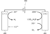
- the electrolytic cell unit 450 can electrolyze tap water flowing in the space (flow path) between the anode plate 454 and the cathode plate 455 by controlling the energization from the control unit 405. .
- the water electrolyzed in the electrolytic cell unit 450 changes to a liquid containing hypochlorous acid.
- the sterilizing water generated in the electrolytic cell unit 450 may be a solution containing metal ions such as silver ions and copper ions.
- the sterilizing water generated in the electrolytic cell unit 450 may be a solution containing electrolytic chlorine, ozone, or the like.
- the sterilizing water generated in the electrolytic cell unit 450 may be acidic water or alkaline water.
- the solution containing hypochlorous acid has stronger sterilizing power.
- the sterilizing water generated in the electrolytic cell unit 450 is a solution containing hypochlorous acid will be described as an example.
- Hypochlorous acid functions as a sterilizing component, and a solution containing the hypochlorous acid, that is, sterilizing water, can efficiently remove or decompose or sterilize dirt caused by ammonia or the like.
- sterilizing water refers to a solution containing more sterilizing components such as hypochlorous acid than tap water (also simply referred to as “water”).
- the electrolytic cell unit 450 electrolyzes tap water to generate a solution containing hypochlorous acid, that is, sterilizing water, a scale such as calcium carbonate (CaCO 3 ) is generated.
- the scale is generated, for example, by combining calcium ions (Ca 2+ ) dissolved in water and carbonate ions (CO 3 2 ⁇ ) generated from carbonic acid (H 2 CO 3 ). If scale is generated and adheres to the surfaces of the anode plate 454 and the cathode plate 455 of the electrolytic cell unit 450, the generation efficiency of hypochlorous acid may be reduced.
- the present inventor found that the pH (pH: hydrogen ion concentration) of the electrolyzed water discharged from the electrolytic cell is high, and that scale is generated and grown after discharging. These will be described in detail later.
- the controller 405 stops energization of the hot water heater 441 when energizing the electrolytic cell unit 450 because the higher the temperature of water during electrolysis, the easier the scale is generated. Or a control to reduce the amount of current supplied to the hot water heater 441 is executed.
- the control unit 405 opens the electromagnetic valve 431 and supplies clean water to the flow path 20 (timing t101).
- the sanitary washing device 100 operates the hot water heater 441. Therefore, the water in the flow path 20 is discharged into the toilet bowl 800 801 and replaced with hot water heated by the hot water heater 441. That is, the control unit 405 operates the warm water heater 441 to start warm water preparation for discharging water from the water outlet 474 (timing t101).
- the execution time of the hot water preparation is, for example, about 6 to 15 seconds.
- the term “clean water” includes not only cold water but also heated hot water.
- the control unit 405 receives a signal for performing body washing. Then, the control unit 405 first executes “pre-cleaning” with clean water (timing t102 to t103). More specifically, the control unit 405 controls the flow rate switching valve 471 and the flow path switching valve 472 to discharge clean water from all the plurality of water discharge ports 474 and to wash the water discharge ports 474. At this time, the control unit 405 does not energize the electrolytic cell unit 450 and does not generate sterilizing water.
- the pre-cleaning execution time is, for example, about 2 to 7 seconds.
- the control unit 405 controls the flow rate switching valve 471 and the flow path switching valve 472 to cause the nozzle 473 to enter the bowl 801 while jetting clean water from the water discharger 479 provided in the nozzle cleaning chamber 478. Let Therefore, the body of the nozzle 473 is washed with clean water sprayed from the water discharger 479 (timing t103 to t104). Also at this time, the control unit 405 does not energize the electrolytic cell unit 450 and does not generate sterilizing water. Therefore, the body of the nozzle 473 is physically washed with clean water sprayed from the water discharger 479.
- the advance time of the nozzle 473 is, for example, about 1.2 to 2.5 seconds.
- control unit 405 controls the flow rate switching valve 471 and the flow path switching valve 472 to inject clean water from the spout 474 for “wet washing”, and the “butt” of the user seated on the toilet seat 200. Is washed (timing t104 to t105). At this time, the control unit 405 does not energize the electrolytic cell unit 450 and does not generate sterilizing water. Therefore, sterilizing water is not sprayed on the user's body. Further, since the warm water heater 441 is operating, the user's body is washed with warm water heated by the warm water heater 441.
- the control unit 405 executes pressure relief control (timing t105 to t106).
- the control unit 405 controls the flow rate switching valve 471 and the flow path switching valve 472 to cause the nozzle 473 to be housed in the casing 400 while ejecting clean water from the water discharger 479 provided in the nozzle cleaning chamber 478. (Timing t106 to t107). That is, the control unit 405 physically cleans the body of the nozzle 473 with the clean water sprayed from the water discharger 479 as in the case of the advance of the nozzle.
- the storage time of the nozzle 473 is, for example, about 1.2 to 2.5 seconds.
- the control unit 405 controls the flow rate switching valve 471 and the flow path switching valve 472 to discharge the clean water from all the plurality of water outlets 474, “Post-cleaning” of these water discharge ports 474 is executed (timing t107 to t108).
- the control unit 405 does not energize the electrolytic cell unit 450 and does not generate sterilizing water. Therefore, the portions of the plurality of water outlets 474 are physically cleaned by the water discharged by the water outlet 474 itself (including the water reflected by the inner wall of the nozzle cleaning chamber 478).
- the pre-cleaning execution time is, for example, about 3 seconds.
- the control unit 405 energizes the electrolytic cell unit 450.
- the sterilizing water is generated in the electrolytic cell unit 450 (timing t109).
- the control unit 405 stops energizing the hot water heater 441 or reduces the energization amount to the hot water heater 441 (timing t109).
- “reducing the energization amount” means energization such that the temperature of the water heated by the hot water heater 441 is lower than the set value of the hot water temperature when performing body washing. It shall be referred to as reducing to an amount.
- the set value of the hot water temperature when performing body washing is, for example, about 30 to 40 ° C.
- control unit 405 When the control unit 405 starts energizing the electrolytic cell unit 450 and there is hot water in the electrolytic cell unit 450, the control unit 405 opens the electromagnetic valve 431 to discharge the hot water from the electrolytic cell unit 450. Then, after the water is replaced with unheated water, energization to the electrolytic cell unit 450 is started.
- control unit 405 opens the electromagnetic valve 431 and supplies sterilizing water to the flow path 20 on the downstream side of the electrolytic cell unit 450 (timing t109). Thereby, the flow path 20 on the downstream side of the electrolytic cell unit 450 is sterilized with the sterilizing water. Further, the control unit 405 controls the flow rate switching valve 471 and the flow path switching valve 472 to discharge the sterilizing water from all of the plurality of water outlets 474 and execute “pre-sterilization” of these water outlets 474. (Timing t109 to t110). Therefore, the portions of the plurality of water outlets 474 are sterilized by the sterilizing water (including the sterilizing water reflected by the inner wall of the nozzle cleaning chamber 478) discharged by the water outlet 474 itself.
- the execution time of the pre-sterilization is about 3 seconds, for example.
- the control unit 405 advances the nozzle 473 into the bowl 801 while controlling the flow rate switching valve 471 and the flow path switching valve 472 to inject sterilizing water from the water discharger 479 provided in the nozzle cleaning chamber 478. And then stored in the casing 400 (timing t110 to t111). That is, the control unit 405 performs “body cleaning” of the nozzle 473 with the sterilizing water sprayed from the water discharge unit 479 (timing t110 to t111). Thereby, the inside of the flow path 20 on the downstream side of the electrolytic cell unit 450 and the body of the nozzle 473 are sterilized with sterilizing water. Note that the execution time of the body cleaning with the sterilizing water is, for example, about 5 seconds.
- the control unit 405 controls the flow rate switching valve 471 and the flow path switching valve 472 to discharge the sterilizing water from all the plurality of water outlets 474, “Post-sterilization” of these water discharge ports 474 is executed (timing t111 to t112). Therefore, the portions of the plurality of water outlets 474 are sterilized by the sterilizing water (including the sterilizing water reflected by the inner wall of the nozzle cleaning chamber 478) discharged by the water outlet 474 itself.
- the execution time of post sterilization is about 3 seconds, for example.
- the control unit 405 closes the electromagnetic valve 431, and then closes the flow path switching valve 472 to hold the sterilized water generated in the electrolytic cell unit 450 in the flow path 20 for a predetermined time (timing t112 to t113). .
- the predetermined time here is, for example, about 60 minutes.
- the control unit 405 performs “draining” (timing t113 to t114). That is, the control unit 405 drains the sterilizing water inside the flow path 20 and makes the inside of the flow path 20 empty.
- the execution time of this “draining” is, for example, about 30 seconds.
- the sanitary washing device 100 holds the sterilizing water in the flow channel 20 for a predetermined time, and then drains the sterilizing water in the flow channel 20 to empty the flow channel 20. Therefore, even when the sterilizing power of the sterilizing water is reduced due to the change over time, the sterilizing water can be prevented from becoming a nutrient source for bacteria.
- the control unit 405 holds the sterilized water generated in the electrolytic cell unit 450 in the flow path 20 for a predetermined time (timing t114 to t115), similarly to the operation described above with respect to the timing t112 to t113. Subsequently, when a predetermined time (for example, about 8 hours in this example) has elapsed since the sanitary washing apparatus 100 was last used, the control unit 405 performs the same operation as described above with respect to the timings t109 to t110 and the timings t111 to t112. “Pre-sterilization” and “Post-sterilization” are executed (timing t115 to t116 and timing t116 to t117).
- a predetermined time for example, about 8 hours in this example
- the control unit 405 starts energization of the electrolytic cell unit 450, generates sterilizing water in the electrolytic cell unit 450, and sterilizes the nozzle 473, thereby energizing the hot water heater 441. Stop or reduce the energization amount to the hot water heater 441. Therefore, when the control unit 405 starts energization of the electrolytic cell unit 450, the water in the electrolytic cell unit 450 is unheated water. Alternatively, when the control unit 405 starts energization of the electrolytic cell unit 450 and there is hot water in the electrolytic cell unit 450, the control unit 405 opens the electromagnetic valve 431 to open the hot water of the electrolytic cell unit 450.
- control unit 405 prevents the water in the flow path 20 and the electrolytic cell unit 450 from freezing even when the energization amount to the hot water heater 441 is reduced.
- the hot water heater 441 may be energized (on / off control of the hot water heater 441) to increase the water temperature.
- the energization amount for preventing freezing is an energization amount such that the temperature of the water heated by the hot water heater 441 is lower than the set value of the hot water temperature when performing body washing. Therefore, even in this case, an increase in scale generation can be suppressed. That is, in the present specification, the range of “reducing the energization amount” includes the case of “energizing the hot water heater 441 when preventing freezing”.
- the controller 405 does not perform sterilization at the temperature of water when the body is washed for the next user. Reduces the energization amount of the hot water heater 441 to such an energization amount that the temperature of the water heated by the hot water heater 441 is lower than the set value of the warm water temperature when performing body washing. Therefore, the nozzle 473 can be sterilized with sterilizing water having a temperature lower than the set value of the temperature of water during body washing. As a result, an increase in scale generation can be suppressed.
- the control unit 405 starts energization of the electrolytic cell unit 450 and generates sterilizing water in the electrolytic cell unit 450. Therefore, it is not necessary to consider the use of the user's body washing, and it is not necessary to keep warm water in the flow path 20. Thereby, the control part 405 can produce
- the warm water heated by the warm water heater 441 may be left in the flow path 20.
- the control unit 405 starts energization of the electrolytic cell unit 450, Bactericidal water is generated in the electrolytic cell unit 450. Therefore, the control unit 405 can sterilize the nozzle 473 after the user has surely left the toilet seat 200.
- the controller 405 may sterilize the nozzle 473 with sterilizing water after the human body detection sensor 403 or the room entry detection sensor 402 no longer detects the user. Even in this case, the control unit 405 can stop the energization of the hot water heater 441 or reduce the energization amount of the hot water heater 441 and generate sterilizing water in the electrolytic cell unit 450. And the increase in the production
- FIG. 5 is a schematic plan view for explaining a scale generated in the electrolytic cell unit of the present embodiment.
- FIG. 6 is a graph showing changes in the dissolution amount of carbonate ions (CO 3 2 ⁇ ) and calcium carbonate (CaCO 3 ) based on changes in pH.
- the electrolytic cell unit 450 has an anode plate 454 and a cathode plate 455 inside thereof, and is controlled between the anode plate 454 and the cathode plate 455 by controlling energization from the control unit 405. It is possible to electrolyze tap water flowing through the space (flow path). At this time, the reaction represented by the formula (1) occurs in the cathode plate 455. H + + e ⁇ ⁇ 1 / 2H 2 ⁇ (1)
- the reaction represented by the formula (4) occurs.
- the tap water contains chlorine ions (Cl ⁇ ).
- This chloride ion is contained as salt (NaCl) or calcium chloride (CaCl 2 ) in a water source (for example, groundwater, dam water, river water, etc.). Therefore, the reaction represented by the formula (5) occurs.
- Chlorine generated in formula (5) is unlikely to exist as bubbles, and most of the chlorine dissolves in water. Therefore, for the chlorine generated in formula (5), the reaction shown in formula (6) occurs.
- hypochlorous acid (HClO) is produced by electrolyzing chlorine ions.
- the water electrolyzed in the electrolytic cell unit 450 changes to a liquid containing hypochlorous acid. Since alkali (OH ⁇ ) is consumed in the anode plate 454, the pH drops in the vicinity of the anode plate 454.
- FIG. 7 is a schematic plan view for explaining a scale generated in the heat exchanger unit of the present embodiment.
- FIG. 8 is a graph showing the change in the dissolved amount of calcium carbonate based on the temperature change.
- the control unit 405 when starting the energization to the electrolytic cell unit 450, the control unit 405 stops the energization to the hot water heater 441 or the energization amount to the hot water heater 441. Reduce. Therefore, when producing the sterilizing water in the electrolytic cell unit 450, it is possible to suppress an increase in the temperature of the water in the electrolytic cell unit 450 and the heat exchanger unit 440. Thereby, the increase in the production
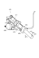
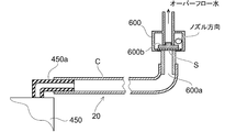
- FIG. 9 is a schematic diagram showing a flow path downstream from the electrolytic cell.
- a flexible tube C such as a silicone tube is externally fitted and connected to the outlet portion 450 a of the electrolytic cell unit 450.
- Reference numeral 600 is a vacuum breaker provided so that downstream water does not flow back to the upstream side, and a flexible tube C is externally fitted and connected to the connecting portion 600a. Since the inner diameter of the connecting portion 600a (constricted portion) is smaller than the inner diameter of the flexible tube, the connecting portion 600a has higher flow resistance than the upstream side, and the flow is disturbed.
- a strainer S and a float valve 600b are arranged on the downstream side of the connection portion 600a, and branch into a discharge flow path for discharging the overflow water of the vacuum breaker and a flow path 20 toward the nozzle 473.
- the said discharge flow path is discharged
- the electrolyzed water electrolyzed in the electrolytic cell unit 450 and discharged from the electrolytic cell unit 450 has an increased pH on the cathode side and a decreased pH on the anode side in the electrolytic cell unit 450 as described above. .
- the pH is in an unbalanced state, but the electrolyzed water discharged from the electrolytic cell unit 450 is still in an unbalanced state.
- the state immediately after being discharged from the electrolytic cell unit 450 is in a high pH state (pH 10).
- This high pH electrolyzed water passes through the flexible tube C and reaches the vacuum breaker 600.
- the flexible tube C is in a state of pH discharged from the electrolytic cell unit 450 without flow resistance. Remains unbalanced.
- the high pH state is suitable as a condition for generating a scale as shown in FIG.
- the flow of electrolyzed water having a high pH is subjected to flow resistance at the connection part 600a (constricted part) of the vacuum breaker 600 having a diameter smaller than the inner diameter of the flexible tube C, and the electrolyzed water is stirred.
- the connection part 600a constricted part
- the electrolyzed water is stirred.
- the dissolved carbonate ions (CO 3 2 ⁇ ) and calcium ions (Ca 2+ ) present in the tap water are easily bonded, and the reaction of the above formula (3) occurs.
- the reaction of formula (3) proceeds, the growth of the scale is promoted by using the small scale piece floating in the electrolytic water as a nucleus, and the scale is generated in the vicinity of the connecting portion 600a.
- a minute scale piece is generated when the polarity of the electrode of the electrolytic cell unit 450 is reversed and is discharged from the electrolytic cell unit 450.
- the electrolyzed water flows down together with the generated scale, but the generated scale is captured by the strainer S because the strainer S is arranged further downstream of the connecting portion 600a. Since the pH imbalance is eliminated by causing flow path resistance at the connecting portion 600a and agitating the electrolyzed water, the pH on the downstream side of the strainer S is lowered and the generation of scale is suppressed. For this reason, the pressure breaker 600, which is disposed downstream of the vacuum breaker 600 and whose flow path is reduced in diameter, the flow path switching valve, and the scale blockage at the nozzle can be suppressed. Of course, the strainer S can also capture relatively large scale pieces discharged from the electrolytic cell unit 450.
- the strainer S is preferably provided in the vicinity of the downstream side of the connection portion 600a where the stirring is sufficiently performed and the pH imbalance is settled. If the strainer S is disposed in the flow path in an unbalanced pH state, a scale may be generated on the downstream side of the strainer S, and a sufficient effect cannot be expected.
- a mesh-like one made of a metal such as stainless steel or a resin can be suitably used.
- the mesh size is appropriately set in consideration of the channel resistance and the size of the scale to be captured so that blockage of the downstream channel can be avoided, but about 18 to 80 mesh can be suitably used.
- the strainer S is preferably a material having a small surface energy such as a fluororesin, a silicone resin, polypropylene, polyethylene, or polystyrene.
- the scale piece is difficult to adhere to the strainer S made of a material having a small surface energy.
- the scale pieces smaller than the mesh size are not supplemented by the strainer S and are flowed downstream, so that blockage due to the strainer scale can be prevented as much as possible.
- the scale pieces generated when the scale is intentionally deposited and the scale is grown by the contraction portion are often small in size. Therefore, the blockage
- scale pieces larger than the mesh size do not adhere to the strainer, and thus are unlikely to become the starting point of scale growth. Therefore, the blockage
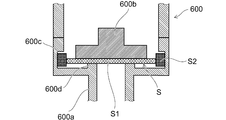
- FIG. 10 is a partially enlarged schematic diagram of FIG. 9 for explaining the fixed state of the strainer S.
- the strainer S includes a resin mesh portion S1 and a fixed edge portion S2.
- the fixed edge portion S2 is placed on the strainer fixing portion 600c and the support portion 600d formed on the inner wall of the vacuum breaker 600, and is not moved by the upstream water pressure.
- the surface energy of the mesh portion S1 to which the strainer is fixed is smaller than the material of the vacuum breaker 600 and smaller than the fixed edge S2 of the strainer S, the scale that does not pass through the mesh is There is a tendency to move outward from the center (in the direction of the strainer fixing portion 600c and the support portion 600d). Therefore, it is possible to suppress the flow path resistance of the strainer S as much as possible.
- strainer S when the strainer S is arranged, it may be made removable so that the scales captured periodically can be cleaned.
- the flow path of the outlet portion 450a is bent or has a small flow path diameter, and is likely to cause flow path resistance, which may cause scale generation and blockage. Therefore, it is made larger than the inner diameter of the upstream flow path so as to suppress the flow resistance as much as possible in the vicinity of the outlet portion 450a, and intentionally induces the generation of scale at the contracted flow section formed downstream thereof. Therefore, the generation of unexpected scale from the flowing down electrolyzed water is suppressed.
- FIG. 11 is a timing chart illustrating a specific example of the operation of the sanitary washing device according to this embodiment.
- the control unit 405 changes the flow rate switching valve 471 and the flow path switching valve 472 from “origin” to “SC (self-cleaning)”.
- the water is switched from all the water outlets 474 for “wet cleaning” and “bide cleaning”.
- the flow rate (water volume) at this time is, for example, about 450 cc / min.
- the control unit 405 opens the electromagnetic valve 431 and causes the hot water heater 441 to be set to the “drainage mode”. Thereby, the cold water in the flow path 20 is drained, and warm water preparation is performed again. Subsequently, when the hot water preparation is completed, the control unit 405 closes the electromagnetic valve 431 and switches the flow rate switching valve 471 and the flow path switching valve 472 from “SC” to “origin (bypass 1)” (timing t203). . Further, the control unit 405 changes the setting of the hot water heater 441 from the “water draining mode” to the “heat retention control mode” (timing t203).
- the control unit 405 receives a signal for performing body washing. Then, the control unit 405 switches the flow rate switching valve 471 and the flow path switching valve 472 from “origin” to “SC”, opens the electromagnetic valve 431, and sets the hot water heater 441 to “pre-cleaning mode, main cleaning mode, post-cleaning”. "Mode" is set.
- the controller 405 does not energize the electrolytic cell unit 450 and does not generate sterilizing water. Further, the control unit 405 sets the warm water heater 441 to the “pre-cleaning mode, main cleaning mode, and post-cleaning mode” to heat the water. Therefore, the portion of the water discharge port 474 is washed with warm water discharged by the water discharge port 474 itself.
- control unit 405 switches the flow rate switching valve 471 and the flow path switching valve 472 from “SC” to “bypass 2” so that water can be injected from the water discharger 479 provided in the nozzle cleaning chamber 478 ( Timing t205). Subsequently, the control unit 405 advances the nozzle 473 housed in the casing 400 to the “wet washing” position (timing t206 to t207).
- control unit 405 opens the electromagnetic valve 431 and does not energize the electrolytic cell unit 450 and does not generate sterilizing water. Further, the control unit 405 sets the warm water heater 441 to the “pre-cleaning mode, main cleaning mode, and post-cleaning mode” to heat the water. Therefore, the body of the nozzle 473 is washed with hot water sprayed from the water discharger 479.
- the control unit 405 switches the flow rate switching valve 471 and the flow path switching valve 472 from “bypass 2” to “wet water flow 5” (timing t207 to t208), and executes main cleaning (wet cleaning) (timing) t208 to t209).
- the control unit 405 includes the flow rate switching valve 471 and the flow path switching valve 472. Is switched from “Oshiri water force 5” to “Oshiri water force 3” (timing t209 to t210). Then, the control unit 405 continues the main cleaning in “water force 3” (timing t210 to t211).
- the control unit 405 does not energize the electrolytic cell unit 450 and does not generate sterilizing water. Therefore, sterilizing water is not sprayed on the user's body. Further, since the warm water heater 441 is set to the “pre-cleaning mode, main cleaning mode, and post-cleaning mode”, the user's body is cleaned with the warm water heated by the warm water heater 441.
- the control unit 405 switches the flow rate switching valve 471 and the flow path switching valve 472 from “wet water pressure 3” to “bypass 2”, Water can be ejected from the water discharger 479 provided in the nozzle cleaning chamber 478 (timing t211). Subsequently, the control unit 405 stores the nozzle 473 that has advanced to the “wet washing” position in the casing 400 (timing t212 to t213).
- control unit 405 opens the electromagnetic valve 431 and does not energize the electrolytic cell unit 450 and does not generate sterilizing water. Further, the control unit 405 sets the warm water heater 441 to the “pre-cleaning mode, main cleaning mode, and post-cleaning mode” to heat the water. Therefore, the body of the nozzle 473 is washed with hot water sprayed from the water discharger 479.
- the control unit 405 switches the flow rate switching valve 471 and the flow path switching valve 472 from “bypass 2” to “SC”, and performs “wet washing” and “bidet”.
- Post-cleaning is performed by discharging water from all the water outlets 474 for “cleaning” (timing t213 to t214).
- the controller 405 opens the electromagnetic valve 431, does not energize the electrolytic cell unit 450, and does not generate sterilizing water. Further, the control unit 405 sets the warm water heater 441 to the “pre-cleaning mode, main cleaning mode, and post-cleaning mode” to heat the water. Therefore, the portion of the water discharge port 474 of the nozzle 473 is washed with warm water discharged by the water discharge port 474 itself.
- control unit 405 closes the electromagnetic valve 431 and switches the flow rate switching valve 471 and the flow path switching valve 472 from “SC” to “origin” (timing t214). Furthermore, the control unit 405 changes the setting of the warm water heater 441 to “pre-cleaning mode, main cleaning mode, post-cleaning mode” to “heat retention control mode” (timing t214).
- the control unit 405 controls the flow rate switching valve 471.
- the flow path switching valve 472 is switched from “origin” to “SC” to enable water discharge from all the water discharge ports 474 for “wet cleaning” and “bidet cleaning” (timing t216).
- the control unit 405 opens the electromagnetic valve 431 (timing t216).
- control unit 405 starts energization of the electrolytic cell unit 450 (timing t217). Furthermore, the control unit 405 changes the setting of the hot water heater 441 from the “freezing prevention mode” to the “heater energization prohibition mode” (timing t217). That is, the control unit 405 stops energization of the hot water heater 441. Thereby, “pre-sterilization” of the water discharge port 474 is executed.
- the control unit 405 After opening the electromagnetic valve 431 (timing t216), the control unit 405 starts energizing the electrolytic cell unit 450 (timing t217). Therefore, even when there is warm water in the electrolytic cell unit 450, the warm water is discharged and replaced with unheated water. That is, the control unit 405 can start energization of the electrolytic cell unit 450 after discharging the hot water of the electrolytic cell unit 450 and replacing it with water that is not heated. Thereby, it can suppress that hot water is electrolyzed and can suppress the increase in the production
- control unit 405 starts energization to the electrolytic cell unit 450 after opening the electromagnetic valve 431, it is possible to prevent the electrolysis cell unit 450 from being energized in the absence of water between the electrodes of the electrolytic cell unit 450. it can. Accordingly, it is possible to prevent the anode plate 454 and the cathode plate 455 from being locally energized, and it is possible to suppress a decrease in the lifetime of the anode plate 454 and the cathode plate 455.
- the control unit 405 switches the flow rate switching valve 471 and the flow path switching valve 472 from “SC” to “origin” (timing t218). Subsequently, the control unit 405 advances the nozzle 473 stored in the casing 400 to the “most advanced” position (timing t219 to t220). At this time, since the control unit 405 opens the electromagnetic valve 431 and energizes the electrolytic cell unit 450, the body of the nozzle 473 is sterilized by the sterilizing water sprayed from the water discharge unit 479. Subsequently, the control unit 405 stores the nozzle 473 that has advanced to the “most advanced” position in the casing 400 (timing t220 to t221). Also at this time, since the control unit 405 opens the electromagnetic valve 431 and energizes the electrolytic cell unit 450, the body of the nozzle 473 is sterilized by the sterilizing water sprayed from the water discharger 479.
- control unit 405 switches the flow rate switching valve 471 and the flow path switching valve 472 from “origin” to “SC”, and discharges water from all the outlets 474 for “wet cleaning” and “bidet cleaning”. (Timing t221). Thereby, “post-sterilization” of the water discharge port 474 is executed.
- control unit 405 stops energization of the electrolytic cell unit 450 and changes the setting of the hot water heater 441 from the “heater energization prohibition mode” to the “freezing prevention mode” (timing t222). Further, the control unit 405 closes the electromagnetic valve 431 and switches the flow rate switching valve 471 and the flow path switching valve 472 from “SC” to “origin” (timing t222).
- the control unit 405 moves the flow rate switching valve 471 and the flow path switching valve 472 from the “origin” to “ It is switched to “SC”, and water discharge from all the water discharge ports 474 for “wet cleaning” and “bidet cleaning” is made possible (timing t223). Furthermore, the control unit 405 opens the electromagnetic valve 431 (timing t223). Thereafter, the control unit 405 starts energization of the electrolytic cell unit 450 (timing t224). Thereby, the regular sterilization of the inside of the flow path 20 and the water discharge port 474 is performed.
- a predetermined time in this case, for example, about 8 hours
- control unit 405 stops energization of the electrolytic cell unit 450 (timing t225). Further, the control unit 405 closes the electromagnetic valve 431 and switches the flow rate switching valve 471 and the flow path switching valve 472 from “SC” to “origin” (timing t225).
- control unit 405 changes the setting of the hot water heater 441 from the “freezing prevention mode” to the “heater energization prohibition mode” when performing “pre-sterilization” (timing t217). It is not limited.
- the control unit 405 may set the warm water heater 441 to remain in the “freezing prevention mode” when performing “pre-sterilization”. That is, at timings t217 to t222, the control unit 405 may set the hot water heater 441 in the “freezing prevention mode”.
- the controller 405 energizes the hot water heater 441 (on / off control of the hot water heater 441) to increase the water temperature.
- the energization amount for preventing freezing is an energization amount such that the temperature of the water heated by the hot water heater 441 is lower than the set value of the hot water temperature when performing body washing. Therefore, even in this case, an increase in scale generation can be suppressed. Further, except in a cold region, the hot water heater 441 is substantially the same as the stopped state even if the “freezing prevention mode” is set.
- the control unit 405 changes the setting of the hot water heater 441 from the “freezing prevention mode” to the “heater energization prohibition mode” when performing “pre-sterilization” (timing t217). . That is, the control unit 405 stops energization of the hot water heater 441 when performing “pre-sterilization”. In this case, the controller 405 does not energize the hot water heater 441 even when the water temperature falls below a predetermined temperature (for example, about 6 ° C.), but the electromagnetic valve 431 is opened and water passes through the flow path 20. Because it is watered, there is little risk of water freezing.
- a predetermined temperature for example, about 6 ° C.
- the control unit 405 starts energization of the electrolytic cell unit 450, generates sterilizing water in the electrolytic cell unit 450, and sterilizes the nozzle 473, The energization to the heater 441 is stopped or the energization amount to the hot water heater 441 is reduced. Therefore, when the control unit 405 starts energization of the electrolytic cell unit 450, the water in the electrolytic cell unit 450 is unheated water. Alternatively, when the control unit 405 starts energization of the electrolytic cell unit 450, the hot water in the electrolytic cell unit 450 is replaced with unheated water. As a result, an increase in scale generation can be suppressed.
- a sanitary washing apparatus capable of suppressing the blockage of the flow path due to the scale.
Landscapes
- Health & Medical Sciences (AREA)
- Public Health (AREA)
- Epidemiology (AREA)
- Life Sciences & Earth Sciences (AREA)
- Engineering & Computer Science (AREA)
- Hydrology & Water Resources (AREA)
- Water Supply & Treatment (AREA)
- Molecular Biology (AREA)
- Bidet-Like Cleaning Device And Other Flush Toilet Accessories (AREA)
Abstract
Description
また、第4の発明は、第2の発明において、前記縮流部は、前記電解槽の出口部から所定間隔を空けて形成することを特徴とする衛生洗浄装置である。
また、第6の発明は、第2の発明において、前記電解槽の出口側の流路を上流側より径の大きい出口部としたことを特徴とする衛生洗浄装置である。
また、第8の発明は、第2の発明において、前記ストレーナは、着脱可能に設けられていることを特徴とする衛生洗浄装置である。
また、第10の発明は、第2の発明において、前記ストレーナは、表面エネルギーの低い材料で形成されていることを特徴とする衛生洗浄装置である。
また、第12の発明は、第10の発明において、前記ストレーナは、前記流路の固定部に固定され、且つ、前記固定部の表面エネルギーは、前記ストレーナの表面エネルギーよりも大きいことを特徴とする衛生洗浄装置である。
また、第14の発明は、第2の発明において、前記ストレーナは、下流側流路に閉塞の恐れの無い粒子は、通過できる網目形状であることを特徴とする衛生洗浄装置である。
図1は、本発明の実施の形態にかかる衛生洗浄装置を備えたトイレ装置を表す斜視模式図である。
また、図2は、本実施形態にかかる衛生洗浄装置の要部構成を表すブロック図である。
そして、制御部405は、電源回路401から電力を供給され、トイレ室への使用者の入室を検知する入室検知センサ(人体検知手段)402や、便座200の前方にいる使用者を検知する人体検知センサ(人体検知手段)403や、便座200への使用者の着座を検知する着座検知センサ404や、操作部500などからの信号に基づいて、電磁弁431や、温水ヒータ441や、電解槽ユニット450や、流量切替弁471や流路切替弁472や、ノズルモータ476の動作を制御することができる。
本実施形態のノズルユニット470は、図3に表したように、基台としての取付台475と、取付台475に支持されたノズル473と、ノズル473を移動させるノズルモータ476と、を有する。ノズル473は、図3に表した矢印Aのように、ベルトなどの伝動部材477を介してノズルモータ476から伝達される駆動力により、取付台475に対して摺動自在に設けられている。すなわち、ノズル473は、ノズル473自身の軸方向(進退方向)に直進移動することができる。そして、ノズル473は、ケーシング400および取付台475から進退自在に移動できる。
なお、図4に表した流路の状態は、電解槽ユニット450よりも下流側の流路20の内部の状態を表している。
次亜塩素酸は、殺菌成分として機能し、その次亜塩素酸を含む溶液すなわち殺菌水は、アンモニアなどによる汚れを効率的に除去あるいは分解したり、殺菌することができる。ここで、本願明細書において「殺菌水」とは、次亜塩素酸などの殺菌成分を水道水(単に「水」ともいう)よりも多く含む溶液をいうものとする。
続いて、衛生洗浄装置100が最後に使用されてから所定時間(ここでは、例えば8時間程度)が経過すると、制御部405は、タイミングt109~t110およびタイミングt111~t112に関して前述した動作と同様に、「前殺菌」および「後殺菌」を実行する(タイミングt115~t116およびタイミングt116~t117)。
また、図6は、pHの変化に基づく炭酸イオン(CO3 2-)および炭酸カルシウム(CaCO3)の溶解量の変化を表すグラフ図である。
H++e- → 1/2H2↑ ・・・(1)
H2CO3 → 2H++CO3 2- ・・・(2)
Ca2++CO3 2- → CaCO3 ・・・(3)
2OH- → 2e-+H2O+1/2O2↑ ・・・(4)
Cl- → e-+1/2Cl2 ・・・(5)
Cl2+H2O → HClO+H++Cl- ・・・(6)
また、図8は、温度変化に基づく炭酸カルシウムの溶解量の変化を表すグラフ図である。
図9において、電解槽ユニット450の出口部450aには、シリコーンチューブなどの可撓性チューブCが外嵌され接続されている。参照符号600は、下流側の水が上流側へ逆流しないように設けられたバキュームブレーカーであり、その接続部600aに可撓性チューブCが、外嵌され接続されている。この接続部600a(縮流部)の内径は、可撓性チューブ内径より小さな径としているので、接続部600aでは、上流側より流路抵抗が高くなり、流れは、乱れを生じる。更に、接続部600aの下流側には、ストレーナSとフロート弁600bが配置され、バキュームブレーカーのオーバーフロー水を排出する排出流路とノズル473に向かう流路20に分岐している。前記排出流路は、便器のボール内に排出されるようになっている。
電解槽ユニット450で電気分解され電解槽ユニット450から排出される電解水は、電解槽ユニット450中では、上述したように陰極側では、pHが上昇し、陽極側では、pHは下降している。そのように電解槽ユニット内では、pHが不均衡な状態であるが、電解槽ユニット450から排出される電解水は、依然として、不均衡な状態である。なお、電解槽ユニット450から排出された直後は、pHの高い(pH10位)状態である場合がほとんどである。この高いpHの電解水は、可撓性チューブCを通過して、バキュームブレーカ600に至るが、可撓性チューブC内は、流路抵抗なく略電解槽ユニット450から排出されたpHの状態のままで、不均衡な状態を維持している。pHの高い状態は、図6に示したようにスケールが生成される条件としては、適している。
まず、着座検知センサ404が便座200に着座した使用者を検知すると(タイミングt201)、制御部405は、流量切替弁471および流路切替弁472を「原点」から「SC(セルフクリーニング)」に切り替えさせ、「おしり洗浄」および「ビデ洗浄」のための全ての吐水口474からの吐水を可能とさせる。このときの流量(水量)は、例えば約450cc/分である。
20 流路
100 衛生洗浄装置
200 便座
300 便蓋
310 透過窓
400 ケーシング
401 電源回路
402 入室検知センサ
403 人体検知センサ
404 着座検知センサ
405 制御部
407 排気口
408 排出口
409 凹設部
431 電磁弁
440 熱交換器ユニット
441 温水ヒータ
450 電解槽ユニット
450 出口部
454 陽極板
455 陰極板
460 圧力変調装置
470 ノズルユニット
471 流量切替弁
472 流路切替弁
473 ノズル
474 吐水口
475 取付台
476 ノズルモータ
477 伝動部材
478 ノズル洗浄室
479 吐水部
500 操作部
600 バキュームブレーカー
600a 接続部
800 便器
801 ボウル
S ストレーナ
C 可撓性チューブ
Claims (14)
- 吐水口を有し、前記吐水口から水を噴射して使用者の身体を洗浄するノズルと、
給水源から供給される水を前記吐水口へ導く流路と、
前記流路の途中に設けられ、殺菌水を生成可能な電解槽と、
前記電解槽により生成された殺菌水にて前記ノズルを洗浄または殺菌するノズル洗浄手段と、
前記電解槽から下流側に流路断面積を上流側より小さくした縮流部を形成し、その更に下流側流路にストレーナを配置したことを特徴とする衛生洗浄装置。 - 便器上部に載置され、吐水口を有し、前記吐水口から前記便器のボウル面に向けて水を吐水するノズルと、
給水源から供給される水を前記吐水口へ導く流路と、
前記流路の途中に設けられ、殺菌水を生成可能な電解槽と、
前記電解槽により生成された殺菌水にて前記ボウル面を洗浄または殺菌するボウル洗浄手段と、
前記電解槽から下流側に流路断面積を上流側より小さくした縮流部を形成し、その更に下流側流路にストレーナを配置したことを特徴とする衛生洗浄装置。 - 前記縮流部は、前記電解槽の出口部から所定間隔を空けて形成することを特徴とする請求項1記載の衛生洗浄装置。
- 前記縮流部は、前記電解槽の出口部から所定間隔を空けて形成することを特徴とする請求項2記載の衛生洗浄装置。
- 前記電解槽の出口側の流路を上流側より径の大きい出口部としたことを特徴とする請求項1記載の衛生洗浄装置。
- 前記電解槽の出口側の流路を上流側より径の大きい出口部としたことを特徴とする請求項2記載の衛生洗浄装置。
- 前記ストレーナは、着脱可能に設けられていることを特徴とする請求項1記載の衛生洗浄装置。
- 前記ストレーナは、着脱可能に設けられていることを特徴とする請求項2記載の衛生洗浄装置。
- 前記ストレーナは、表面エネルギーの低い材料で形成されていることを特徴とする請求項1記載の衛生洗浄装置。
- 前記ストレーナは、表面エネルギーの低い材料で形成されていることを特徴とする請求項2記載の衛生洗浄装置。
- 前記ストレーナは、前記流路の固定部に固定され、且つ、前記固定部の表面エネルギーは、前記ストレーナの表面エネルギーよりも大きいことを特徴とする請求項9記載の衛生洗浄装置。
- 前記ストレーナは、前記流路の固定部に固定され、且つ、前記固定部の表面エネルギーは、前記ストレーナの表面エネルギーよりも大きいことを特徴とする請求項10記載の衛生洗浄装置。
- 前記ストレーナは、下流側流路に閉塞の恐れの無い粒子は、通過できる網目形状であることを特徴とする請求項1記載の衛生洗浄装置。
- 前記ストレーナは、下流側流路に閉塞の恐れの無い粒子は、通過できる網目形状であることを特徴とする請求項2記載の衛生洗浄装置。
Priority Applications (4)
| Application Number | Priority Date | Filing Date | Title |
|---|---|---|---|
| EP11812536.8A EP2599926B1 (en) | 2010-07-28 | 2011-07-27 | Sanitary cleaning device |
| US13/812,234 US8856979B2 (en) | 2010-07-28 | 2011-07-27 | Sanitary washing apparatus |
| KR1020137001690A KR101439192B1 (ko) | 2010-07-28 | 2011-07-27 | 위생 세정 장치 |
| CN201180036019.6A CN103025972B (zh) | 2010-07-28 | 2011-07-27 | 卫生洗净装置 |
Applications Claiming Priority (4)
| Application Number | Priority Date | Filing Date | Title |
|---|---|---|---|
| JP2010-168749 | 2010-07-28 | ||
| JP2010168749 | 2010-07-28 | ||
| JP2011-056033 | 2011-03-15 | ||
| JP2011056033A JP5093762B2 (ja) | 2010-07-28 | 2011-03-15 | 衛生洗浄装置 |
Publications (1)
| Publication Number | Publication Date |
|---|---|
| WO2012014947A1 true WO2012014947A1 (ja) | 2012-02-02 |
Family
ID=45530150
Family Applications (1)
| Application Number | Title | Priority Date | Filing Date |
|---|---|---|---|
| PCT/JP2011/067148 WO2012014947A1 (ja) | 2010-07-28 | 2011-07-27 | 衛生洗浄装置 |
Country Status (7)
| Country | Link |
|---|---|
| US (1) | US8856979B2 (ja) |
| EP (1) | EP2599926B1 (ja) |
| JP (1) | JP5093762B2 (ja) |
| KR (1) | KR101439192B1 (ja) |
| CN (1) | CN103025972B (ja) |
| TW (1) | TWI473927B (ja) |
| WO (1) | WO2012014947A1 (ja) |
Families Citing this family (18)
| Publication number | Priority date | Publication date | Assignee | Title |
|---|---|---|---|---|
| JP5093762B2 (ja) * | 2010-07-28 | 2012-12-12 | Toto株式会社 | 衛生洗浄装置 |
| JP5327727B2 (ja) * | 2012-02-14 | 2013-10-30 | Toto株式会社 | トイレ装置 |
| WO2013134525A2 (en) | 2012-03-07 | 2013-09-12 | Moen Incorporated | Electronic plumbing fixture fitting |
| JP2015147162A (ja) * | 2014-02-05 | 2015-08-20 | Toto株式会社 | 電解水生成装置および衛生洗浄装置 |
| KR101837619B1 (ko) * | 2014-02-13 | 2018-03-13 | 코웨이 주식회사 | 비데용 물 저장장치 및 이를 포함하는 비데 |
| CN104775490B (zh) * | 2015-03-09 | 2016-06-08 | 厦门优胜卫厨科技有限公司 | 一种清洁装置及其清洁方法 |
| JP2017025561A (ja) * | 2015-07-22 | 2017-02-02 | Toto株式会社 | トイレ装置 |
| JP1572278S (ja) * | 2015-08-28 | 2017-03-27 | ||
| JP6676313B2 (ja) * | 2015-08-31 | 2020-04-08 | 株式会社Lixil | 除菌装置および便器 |
| CN108349760A (zh) | 2015-12-04 | 2018-07-31 | 吉博力国际股份公司 | 淋浴厕所 |
| JP6541096B2 (ja) * | 2016-08-24 | 2019-07-10 | Toto株式会社 | 衛生洗浄装置 |
| KR20190037294A (ko) * | 2016-12-28 | 2019-04-05 | 토토 가부시키가이샤 | 전해수 생성 장치 |
| JP1608415S (ja) * | 2018-01-22 | 2021-07-05 | ||
| JP2019173350A (ja) * | 2018-03-28 | 2019-10-10 | 株式会社Lixil | 局部洗浄装置 |
| US10851533B2 (en) * | 2018-06-01 | 2020-12-01 | Toto Ltd. | Sanitary washing device |
| JP6979175B2 (ja) * | 2019-07-05 | 2021-12-08 | Toto株式会社 | 衛生洗浄装置 |
| JP7380147B2 (ja) * | 2019-11-29 | 2023-11-15 | Toto株式会社 | 衛生洗浄装置 |
| JP7398048B2 (ja) | 2019-11-29 | 2023-12-14 | Toto株式会社 | 衛生洗浄装置 |
Citations (5)
| Publication number | Priority date | Publication date | Assignee | Title |
|---|---|---|---|---|
| JPS6434156A (en) | 1987-07-28 | 1989-02-03 | Matsushita Electric Works Ltd | Permanent magnet |
| JPH08193346A (ja) * | 1995-01-18 | 1996-07-30 | Minolta Co Ltd | 便器の水洗装置 |
| JP3487447B2 (ja) | 1994-09-27 | 2004-01-19 | 東陶機器株式会社 | 局部洗浄装置 |
| JP2005155098A (ja) | 2003-11-21 | 2005-06-16 | Matsushita Electric Works Ltd | 局部洗浄装置 |
| JP2009225888A (ja) * | 2008-03-19 | 2009-10-08 | Toto Ltd | 浴室殺菌システム |
Family Cites Families (21)
| Publication number | Priority date | Publication date | Assignee | Title |
|---|---|---|---|---|
| US2051030A (en) * | 1931-03-20 | 1936-08-18 | Joseph Z Dalinda | Method and apparatus for smoking |
| US3425414A (en) * | 1965-05-28 | 1969-02-04 | William J La Roche | Inhalant dispenser |
| US4393884A (en) * | 1981-09-25 | 1983-07-19 | Jacobs Allen W | Demand inhaler for oral administration of tobacco, tobacco-like, or other substances |
| TW272244B (ja) | 1994-08-19 | 1996-03-11 | Toto Ltd | |
| WO1999053150A1 (fr) * | 1998-04-08 | 1999-10-21 | Toto Ltd. | Douchette de nettoyage corporel |
| EP1237610B1 (en) * | 1999-11-08 | 2006-05-10 | Capnia Incorporated | Apparatus for co-application of gases and drugs |
| JP2001279780A (ja) * | 2000-03-31 | 2001-10-10 | Toto Ltd | 銀イオン電解装置付局部洗浄装置 |
| DE10259997B4 (de) * | 2002-12-20 | 2007-09-13 | Airbus Deutschland Gmbh | Flugzeugtoilettensystem |
| JP2005007348A (ja) * | 2003-06-20 | 2005-01-13 | Matsushita Electric Ind Co Ltd | 電気脱イオン装置 |
| JP2006097311A (ja) * | 2004-09-29 | 2006-04-13 | Sanyo Electric Co Ltd | 水洗トイレ及び水洗トイレの脱臭方法 |
| CN1840789B (zh) * | 2005-04-01 | 2011-05-11 | 三洋电机株式会社 | 坐便座用清洗装置 |
| JP5617151B2 (ja) * | 2007-01-10 | 2014-11-05 | パナソニック株式会社 | 衛生洗浄装置 |
| JP4794589B2 (ja) * | 2008-03-12 | 2011-10-19 | パナソニック株式会社 | 衛生洗浄装置 |
| JP2009225886A (ja) | 2008-03-19 | 2009-10-08 | Toto Ltd | 浴室殺菌システム |
| GB0808154D0 (en) * | 2008-05-06 | 2008-06-11 | British American Tobacco Co | Aerosol dispensing device |
| KR101082017B1 (ko) | 2009-05-21 | 2011-11-10 | 최장수 | 스트레이너/필터 기능을 가지는 전해장치 및 이를 이용하는 유체유동 시스템 |
| WO2011016389A1 (ja) * | 2009-08-06 | 2011-02-10 | Toto株式会社 | 衛生洗浄装置 |
| JP5601570B2 (ja) * | 2009-08-06 | 2014-10-08 | Toto株式会社 | 衛生洗浄装置 |
| EP2305903A1 (en) * | 2009-09-28 | 2011-04-06 | Toto Ltd. | Washing device for user's private parts |
| JP4756404B1 (ja) * | 2010-06-18 | 2011-08-24 | Toto株式会社 | 衛生洗浄装置 |
| JP5093762B2 (ja) * | 2010-07-28 | 2012-12-12 | Toto株式会社 | 衛生洗浄装置 |
-
2011
- 2011-03-15 JP JP2011056033A patent/JP5093762B2/ja active Active
- 2011-07-27 EP EP11812536.8A patent/EP2599926B1/en active Active
- 2011-07-27 CN CN201180036019.6A patent/CN103025972B/zh active Active
- 2011-07-27 TW TW100126577A patent/TWI473927B/zh active
- 2011-07-27 WO PCT/JP2011/067148 patent/WO2012014947A1/ja active Application Filing
- 2011-07-27 KR KR1020137001690A patent/KR101439192B1/ko active IP Right Grant
- 2011-07-27 US US13/812,234 patent/US8856979B2/en active Active
Patent Citations (5)
| Publication number | Priority date | Publication date | Assignee | Title |
|---|---|---|---|---|
| JPS6434156A (en) | 1987-07-28 | 1989-02-03 | Matsushita Electric Works Ltd | Permanent magnet |
| JP3487447B2 (ja) | 1994-09-27 | 2004-01-19 | 東陶機器株式会社 | 局部洗浄装置 |
| JPH08193346A (ja) * | 1995-01-18 | 1996-07-30 | Minolta Co Ltd | 便器の水洗装置 |
| JP2005155098A (ja) | 2003-11-21 | 2005-06-16 | Matsushita Electric Works Ltd | 局部洗浄装置 |
| JP2009225888A (ja) * | 2008-03-19 | 2009-10-08 | Toto Ltd | 浴室殺菌システム |
Also Published As
| Publication number | Publication date |
|---|---|
| CN103025972B (zh) | 2014-12-03 |
| JP2012047030A (ja) | 2012-03-08 |
| US20130185861A1 (en) | 2013-07-25 |
| EP2599926B1 (en) | 2018-02-21 |
| US8856979B2 (en) | 2014-10-14 |
| EP2599926A4 (en) | 2017-05-03 |
| KR20130032367A (ko) | 2013-04-01 |
| TWI473927B (zh) | 2015-02-21 |
| CN103025972A (zh) | 2013-04-03 |
| KR101439192B1 (ko) | 2014-09-12 |
| JP5093762B2 (ja) | 2012-12-12 |
| TW201207201A (en) | 2012-02-16 |
| EP2599926A1 (en) | 2013-06-05 |
Similar Documents
| Publication | Publication Date | Title |
|---|---|---|
| JP5093762B2 (ja) | 衛生洗浄装置 | |
| JP4756404B1 (ja) | 衛生洗浄装置 | |
| JP5601570B2 (ja) | 衛生洗浄装置 | |
| JP5741857B2 (ja) | 衛生洗浄装置 | |
| JP2012125715A (ja) | 電気分解装置および衛生洗浄装置 | |
| JP2012082615A (ja) | 衛生洗浄装置 | |
| JP2012067442A (ja) | 衛生洗浄装置 | |
| JP5660519B2 (ja) | 衛生洗浄装置 | |
| JP5678540B2 (ja) | 衛生洗浄装置 | |
| JP5954681B2 (ja) | 衛生洗浄装置 | |
| JP4780244B1 (ja) | 衛生洗浄装置 | |
| JP6635404B2 (ja) | 衛生洗浄装置 | |
| JP2011202480A (ja) | 衛生洗浄装置 | |
| JP2019027015A (ja) | 衛生洗浄装置 | |
| JP2019027014A (ja) | 衛生洗浄装置 | |
| JP2011252371A (ja) | 衛生洗浄装置 | |
| JP2013221245A (ja) | 局部洗浄装置 | |
| JP2000240124A (ja) | 局部洗浄装置 |
Legal Events
| Date | Code | Title | Description |
|---|---|---|---|
| WWE | Wipo information: entry into national phase |
Ref document number: 201180036019.6 Country of ref document: CN |
|
| 121 | Ep: the epo has been informed by wipo that ep was designated in this application |
Ref document number: 11812536 Country of ref document: EP Kind code of ref document: A1 |
|
| ENP | Entry into the national phase |
Ref document number: 20137001690 Country of ref document: KR Kind code of ref document: A |
|
| WWE | Wipo information: entry into national phase |
Ref document number: 2011812536 Country of ref document: EP |
|
| NENP | Non-entry into the national phase |
Ref country code: DE |
|
| WWE | Wipo information: entry into national phase |
Ref document number: 13812234 Country of ref document: US |