WO2012014663A1 - 蛍光体封入用毛細管の製造方法、蛍光体封入用毛細管、波長変換部材及び波長変換部材の製造方法 - Google Patents
蛍光体封入用毛細管の製造方法、蛍光体封入用毛細管、波長変換部材及び波長変換部材の製造方法 Download PDFInfo
- Publication number
- WO2012014663A1 WO2012014663A1 PCT/JP2011/065765 JP2011065765W WO2012014663A1 WO 2012014663 A1 WO2012014663 A1 WO 2012014663A1 JP 2011065765 W JP2011065765 W JP 2011065765W WO 2012014663 A1 WO2012014663 A1 WO 2012014663A1
- Authority
- WO
- WIPO (PCT)
- Prior art keywords
- capillary
- phosphor
- encapsulating
- capillary tube
- glass
- Prior art date
- Legal status (The legal status is an assumption and is not a legal conclusion. Google has not performed a legal analysis and makes no representation as to the accuracy of the status listed.)
- Ceased
Links
- NSVCTLOLDNKUEQ-UHFFFAOYSA-N CCCC1=C(CC)CCC1 Chemical compound CCCC1=C(CC)CCC1 NSVCTLOLDNKUEQ-UHFFFAOYSA-N 0.000 description 1
Images













Classifications
-
- C—CHEMISTRY; METALLURGY
- C03—GLASS; MINERAL OR SLAG WOOL
- C03B—MANUFACTURE, SHAPING, OR SUPPLEMENTARY PROCESSES
- C03B23/00—Re-forming shaped glass
- C03B23/04—Re-forming tubes or rods
- C03B23/13—Reshaping combined with uniting or heat sealing, e.g. for making vacuum bottles
-
- C—CHEMISTRY; METALLURGY
- C03—GLASS; MINERAL OR SLAG WOOL
- C03B—MANUFACTURE, SHAPING, OR SUPPLEMENTARY PROCESSES
- C03B23/00—Re-forming shaped glass
- C03B23/04—Re-forming tubes or rods
- C03B23/09—Reshaping the ends, e.g. as grooves, threads or mouths
- C03B23/099—Reshaping the ends, e.g. as grooves, threads or mouths by fusing, e.g. flame sealing
-
- C—CHEMISTRY; METALLURGY
- C03—GLASS; MINERAL OR SLAG WOOL
- C03B—MANUFACTURE, SHAPING, OR SUPPLEMENTARY PROCESSES
- C03B23/00—Re-forming shaped glass
- C03B23/20—Uniting glass pieces by fusing without substantial reshaping
- C03B23/207—Uniting glass rods, glass tubes, or hollow glassware
-
- G—PHYSICS
- G02—OPTICS
- G02F—OPTICAL DEVICES OR ARRANGEMENTS FOR THE CONTROL OF LIGHT BY MODIFICATION OF THE OPTICAL PROPERTIES OF THE MEDIA OF THE ELEMENTS INVOLVED THEREIN; NON-LINEAR OPTICS; FREQUENCY-CHANGING OF LIGHT; OPTICAL LOGIC ELEMENTS; OPTICAL ANALOGUE/DIGITAL CONVERTERS
- G02F1/00—Devices or arrangements for the control of the intensity, colour, phase, polarisation or direction of light arriving from an independent light source, e.g. switching, gating or modulating; Non-linear optics
- G02F1/01—Devices or arrangements for the control of the intensity, colour, phase, polarisation or direction of light arriving from an independent light source, e.g. switching, gating or modulating; Non-linear optics for the control of the intensity, phase, polarisation or colour
- G02F1/13—Devices or arrangements for the control of the intensity, colour, phase, polarisation or direction of light arriving from an independent light source, e.g. switching, gating or modulating; Non-linear optics for the control of the intensity, phase, polarisation or colour based on liquid crystals, e.g. single liquid crystal display cells
- G02F1/133—Constructional arrangements; Operation of liquid crystal cells; Circuit arrangements
- G02F1/1333—Constructional arrangements; Manufacturing methods
- G02F1/1335—Structural association of cells with optical devices, e.g. polarisers or reflectors
- G02F1/1336—Illuminating devices
- G02F1/133617—Illumination with ultraviolet light; Luminescent elements or materials associated to the cell
-
- Y—GENERAL TAGGING OF NEW TECHNOLOGICAL DEVELOPMENTS; GENERAL TAGGING OF CROSS-SECTIONAL TECHNOLOGIES SPANNING OVER SEVERAL SECTIONS OF THE IPC; TECHNICAL SUBJECTS COVERED BY FORMER USPC CROSS-REFERENCE ART COLLECTIONS [XRACs] AND DIGESTS
- Y02—TECHNOLOGIES OR APPLICATIONS FOR MITIGATION OR ADAPTATION AGAINST CLIMATE CHANGE
- Y02P—CLIMATE CHANGE MITIGATION TECHNOLOGIES IN THE PRODUCTION OR PROCESSING OF GOODS
- Y02P40/00—Technologies relating to the processing of minerals
- Y02P40/50—Glass production, e.g. reusing waste heat during processing or shaping
- Y02P40/57—Improving the yield, e-g- reduction of reject rates
-
- Y—GENERAL TAGGING OF NEW TECHNOLOGICAL DEVELOPMENTS; GENERAL TAGGING OF CROSS-SECTIONAL TECHNOLOGIES SPANNING OVER SEVERAL SECTIONS OF THE IPC; TECHNICAL SUBJECTS COVERED BY FORMER USPC CROSS-REFERENCE ART COLLECTIONS [XRACs] AND DIGESTS
- Y10—TECHNICAL SUBJECTS COVERED BY FORMER USPC
- Y10T—TECHNICAL SUBJECTS COVERED BY FORMER US CLASSIFICATION
- Y10T428/00—Stock material or miscellaneous articles
- Y10T428/13—Hollow or container type article [e.g., tube, vase, etc.]
- Y10T428/131—Glass, ceramic, or sintered, fused, fired, or calcined metal oxide or metal carbide containing [e.g., porcelain, brick, cement, etc.]
Definitions
- the present invention relates to a method for producing a capillary for encapsulating a phosphor, a capillary for encapsulating a phosphor, a wavelength conversion member, and a method for producing a wavelength conversion member.
- white light sources used for applications such as backlights for liquid crystal displays have been actively developed.
- a white light source for example, in Patent Document 1 below, a part of light from an LED is absorbed on the light emitting side of an LED (Light Emitting Diode) that emits blue light, and yellow light is emitted.
- a light source in which a wavelength conversion member is arranged is disclosed. From this light source, white light that is a combined light of blue light emitted from the LED and transmitted through the wavelength conversion member and yellow light emitted from the wavelength conversion member is emitted.
- the direct type backlight has an advantage that a relatively high luminance is easily obtained, but has a disadvantage that the thickness dimension is likely to be large because the planar light source and the diffusion plate are laminated.
- the edge light type backlight the light source is arranged on the side of the light guide. For this reason, the edge light type backlight has an advantage that it can be made thinner than the direct type backlight. Therefore, edge-light type backlights are widely used for applications that are strongly required to be thin, such as liquid crystal displays for mobile phones and liquid crystal displays for notebook personal computers.
- edge light type backlight in order to obtain uniform planar light with small luminance unevenness, it is necessary to make light uniformly incident on the side surface of the light guide. For this reason, a white linear light source is preferably used in the edge light type backlight.
- a white linear light source for example, a plurality of LEDs that emit blue light arranged in a straight line (hereinafter referred to as “blue LEDs”) and a linear that is arranged in front of the plurality of blue LEDs.
- the one provided with the wavelength conversion member for example, a member including a capillary and a phosphor sealed in the capillary can be considered.
- a glass flat plate is fused or bonded to the other end of the glass capillary to seal it. It is also conceivable to manufacture a shaped wavelength conversion member.
- the present invention has been made in view of the above points, and a method for manufacturing a capillary for encapsulating a phosphor, in which fluorescence from the phosphor hardly leaks from an end when the phosphor is encapsulated, and a capillary for encapsulating the phosphor Is to provide.
- the method for producing a capillary for encapsulating a phosphor according to the present invention includes a phosphor encapsulation in which one end is sealed while the other end is open and the phosphor is encapsulated from the other end.
- the present invention relates to a method for manufacturing a capillary tube.
- the manufacturing method of the capillary for encapsulating a phosphor according to the present invention includes a heating step.
- the heating step is a step of heating the one end portion of the glass capillary until the one end portion of the elongated glass capillary whose outer shape in the cross section is elongated in the width direction is melted and sealed. .
- the light emitted from the encapsulated phosphor toward the end of the capillary for encapsulating the phosphor is preferably reflected toward the inside of the capillary for encapsulating the phosphor. Is done. A part of the reflected light is emitted from the side wall of the phosphor encapsulating capillary.
- the phosphor from the encapsulated phosphor is unlikely to leak out from the end portion, and the phosphor encapsulation that can increase the efficiency of extracting light from the tube wall Capillary tubes can be manufactured.
- the dimension in the width direction of the one side end of the glass capillary decreases toward the tip side, while the width direction of the one side end of the glass capillary It is preferable to heat the one end of the glass capillary so that the dimension in the thickness direction perpendicular to the thickness once increases toward the tip side and then decreases.
- the maximum dimension in the thickness direction of one end of the glass capillary is a dimension along the thickness direction of the portion excluding the one end of the glass capillary. It is preferable to heat one end portion of the glass capillary tube so that it becomes 1.1 to 3.0 times as large as.
- the dimensions in the width direction and the thickness direction perpendicular to the width direction of the one side end portion of the glass capillary tube decrease toward the tip side.
- the maximum dimension in the thickness direction of the one end portion of the glass capillary tube is less than one time the dimension along the thickness direction of the portion excluding the one end portion of the glass capillary tube.
- the heating step is performed by heating and sealing one end portion of the glass capillary tube by causing the heating means to cross over the one end portion of the glass capillary tube.
- 1 heating step, and a second heating step of heating the one end of the glass capillary again by traversing the heating means on the one end of the glass capillary in the direction opposite to the first heating step. are preferably included.
- one end of the glass capillary is not thicker than a portion of the glass capillary other than the one end of the glass capillary. It is preferable to set the heating temperature by the heating means and the moving speed of the heating means.
- the heating means in the thickness direction of the glass capillary in the first and second heating steps.
- a laser irradiation apparatus may be used as a heating means. In that case, it is preferable to heat the one end portion of the glass capillary by irradiating the one end portion of the glass capillary with a laser by a laser irradiation device.
- the method for producing a capillary for encapsulating a phosphor it is preferable to use a laser irradiation device in which the spot shape of the laser light is an elongated shape elongated in the width direction of the glass capillary as the laser irradiation device.
- the time during which laser light is irradiated to one end of the glass capillary in the first and second heating steps is determined by laser irradiation. It is preferable to use a laser irradiation apparatus that irradiates a spot-shaped laser beam that is constant in a direction perpendicular to the moving direction of the apparatus.
- laser irradiation is performed in which laser light intensity is approximately constant at the center of the laser light spot in the width direction of the glass capillary tube. It is preferable to use an apparatus.
- a burner may be used as a heating means.
- the first capillary for encapsulating a phosphor according to the present invention is manufactured by the method for manufacturing a capillary for encapsulating a phosphor according to the present invention. Therefore, the fluorescence from the encapsulated phosphor is difficult to leak from the end. Therefore, the light extraction efficiency from the tube wall of the wavelength conversion member can be increased by configuring the wavelength conversion member using the first phosphor-encapsulating capillary according to the present invention. As a result, by using this wavelength conversion member, a high-luminance edge light type backlight can be realized.
- the second capillary for encapsulating a phosphor according to the present invention has a phosphor encapsulated in which one end is sealed while the other end is open and the phosphor is encapsulated from the other end.
- a second phosphor-encapsulating capillary according to the present invention has an elongated shape in which the outer shape in the cross section is elongated in the width direction, and has a straight tubular capillary body having a substantially constant thickness, and one end portion of the capillary body. The sealing part which is sealing is provided.
- the sealing portion is formed so that the dimension in the width direction becomes smaller toward the tip side, while the dimension in the thickness direction perpendicular to the width direction becomes smaller once the dimension in the thickness direction becomes larger toward the tip side. Therefore, the fluorescence from the encapsulated phosphor hardly leaks from the end portion, and the light extraction efficiency from the tube wall can be increased. Therefore, by using the second phosphor encapsulating capillary according to the present invention, a high-luminance edge light type backlight can be realized.
- the maximum dimension in the thickness direction of the sealing portion is preferably 1.1 to 3.0 times the dimension along the thickness direction of the capillary body.
- a third phosphor-encapsulating capillary according to the present invention has an elongated shape in which the outer shape in the cross section is elongated in the width direction, and has a straight tubular capillary body having a substantially constant thickness, and one end portion of the capillary body.
- the sealing part which is sealing is provided. The sealing part is formed so that the dimension in each of the width direction and the thickness direction perpendicular to the width direction becomes smaller toward the tip side.
- the fluorescence from the encapsulated phosphor hardly leaks from the end portion, and the light extraction efficiency from the tube wall can be increased. Therefore, by using the third phosphor-encapsulating capillary according to the present invention, a high-luminance edge light type backlight can be realized.
- the sealing portion has a side wall portion and a bottom wall portion constituting a recess opening in the through hole of the capillary body, It is preferable that at least a part of the bottom wall portion is formed in a planar shape whose normal direction is parallel to the central axis of the capillary body.
- the center portion of the bottom wall portion is formed so that the normal direction faces the central axis side of the capillary body.
- the bottom wall portion is centered more than the portion where the dimension in the thickness direction of the sealing portion is maximum. It is preferably located on the side.
- the capillary body is preferably formed in a square tube shape.
- the first wavelength conversion member according to the present invention includes a capillary tube sealed at both ends, and a phosphor sealed in the capillary tube.
- the capillary is a straight tubular capillary body whose outer shape in the cross section is elongated in the width direction and has a substantially constant thickness, and a first sealing portion that seals one end of the capillary body. And a second sealing portion sealing the other end portion of the capillary body. At least one of the first and second sealing portions has a size in the width direction that decreases toward the tip side, while a size in the thickness direction perpendicular to the width direction decreases once the size in the thickness direction increases toward the tip side. It is formed as follows.
- the first wavelength conversion member according to the present invention a high-luminance edge light type backlight can be realized.
- the second wavelength conversion member according to the present invention includes a capillary tube whose both ends are sealed, and a phosphor sealed in the capillary tube.
- the capillary is a straight tubular capillary body whose outer shape in the cross section is elongated in the width direction and has a substantially constant thickness, and a first sealing portion that seals one end of the capillary body. And a second sealing portion sealing the other end portion of the capillary body. At least one of the first and second sealing portions is formed so that the dimension in each of the width direction and the thickness direction perpendicular to the width direction decreases toward the tip side.
- the second wavelength conversion member according to the present invention a high-luminance edge light type backlight can be realized.
- the method for producing a wavelength conversion member according to the present invention includes a step of injecting a phosphor from one of the other end portions of the first to third phosphor encapsulating capillaries, and a phosphor into which the phosphor is injected. And a first end sealing step for sealing the other end of the sealing capillary.
- the present invention it is possible to provide a method for manufacturing a capillary for encapsulating a phosphor and a capillary for encapsulating a phosphor, in which when the phosphor is encapsulated, the fluorescence from the phosphor is less likely to leak from the end.
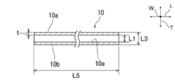
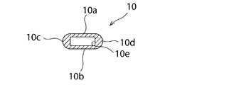
- FIG. 1 is a schematic perspective view of a glass capillary tube according to the first embodiment.
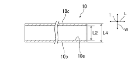
- FIG. 2 is a schematic cross-sectional view taken along line II-II in FIG. 3 is a schematic cross-sectional view taken along line III-III in FIG.
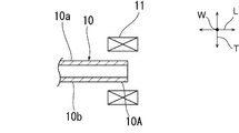
- FIG. 4 is a schematic cross-sectional view for explaining a heating process in the first embodiment.
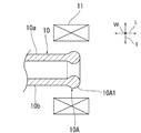
- FIG. 5 is a schematic cross-sectional view for explaining a heating step in the first embodiment.
- FIG. 6 is a schematic cross-sectional view for explaining a heating step in the first embodiment.
- FIG. 7 is a schematic cross-sectional view for explaining a heating step in the first embodiment.
- FIG. 8 is a schematic cross-sectional view of a phosphor-encapsulating capillary tube in the first embodiment.
- FIG. 9 is a schematic cross-sectional view of the phosphor encapsulating capillary tube according to the first embodiment.
- FIG. 10 is a schematic cross-sectional view of a capillary tube for encapsulating a phosphor according to a modification of the first embodiment.
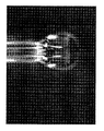
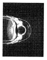
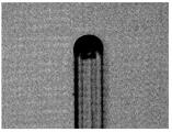
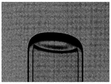
- FIG. 11 is a plan photograph of the phosphor encapsulating capillary produced in the example.
- FIG. 12 is a side view photograph of a phosphor-encapsulating capillary tube produced in the example.
- FIG. 13 is a schematic perspective view of a glass capillary tube according to the second embodiment.
- FIG. 14 is a schematic cross-sectional view taken along line II-II in FIG. 15 is a schematic cross-sectional view taken along line III-III in FIG.
- FIG. 14 is a schematic cross-sectional
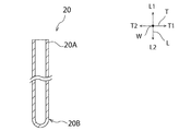
- FIG. 16 is a schematic side view for explaining the sealing step of the second end of the glass capillary tube in the second embodiment.
- FIG. 17 is a schematic plan view for explaining the shape of the spot diameter of the laser in the second embodiment.
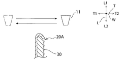
- FIG. 18 is a schematic side view for explaining a sealing step of the second end portion of the glass capillary tube in the second embodiment.
- FIG. 19 is a schematic side view for explaining a sealing step of the second end of the glass capillary tube in the second embodiment.
- FIG. 20 is a schematic cross-sectional view of a phosphor-encapsulating capillary tube according to the second embodiment.
- FIG. 21 is a schematic cross-sectional view for explaining the step of injecting the phosphor into the phosphor-encapsulating capillary in the second embodiment.
- FIG. 22 is a schematic side view for explaining the sealing step of the first end of the phosphor-encapsulating capillary in the second embodiment.
- FIG. 23 is a schematic side view for explaining a sealing step of the first end of the phosphor-encapsulating capillary tube in the second embodiment.
- FIG. 24 is a schematic side view for explaining the sealing step of the first end of the phosphor-encapsulating capillary tube according to the second embodiment.
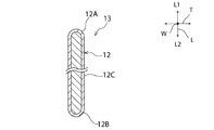
- FIG. 25 is a schematic cross-sectional view of a wavelength conversion member in the second embodiment.
- FIG. 26 is a schematic plan view for explaining the shape of the spot diameter of the laser according to the first modification of the second embodiment.
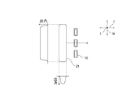
- FIG. 27 is a side view of the end of the wavelength conversion member as viewed from the width direction.
- FIG. 28 is a side view of the end of the wavelength conversion member viewed from the thickness direction.
- FIG. 29 is a schematic plan view for explaining the shape of the laser spot diameter and the laser output distribution according to the second modification of the second embodiment.
- FIG. 30 is a schematic cross-sectional view of a glass capillary tube in a modified example.
- FIG. 31 is a schematic cross-sectional view of a glass capillary tube according to a modification.
- FIG. 32 is a schematic cross-sectional view of a glass capillary tube according to a modification.
- FIG. 1 is a schematic perspective view of a glass capillary tube.
- FIG. 2 is a schematic cross-sectional view taken along line II-II in FIG. 3 is a schematic cross-sectional view taken along line III-III in FIG.
- the glass capillary tube 10 has an elongated shape whose outer shape in a transverse section (that is, a section along the width direction W and the thickness direction T) is elongated in the width direction W.
- the glass capillary tube 10 is formed in a rectangular tube shape.
- square tube means a straight tube whose outer shape and inner shape are rectangular when viewed from the length direction L.
- the “rectangle” includes a rectangle whose corners are chamfered or rounded.
- the glass capillary tube 10 has flat plate-like first and second side wall portions 10a, 10b facing each other and flat plate-like third and fourth side wall portions 10c, 10d facing each other.
- a prismatic through hole 10e is defined by the first to fourth side wall portions 10a to 10d.
- the dimensions of the glass capillary tube 10 are not particularly limited.
- the wall thickness t (see FIG. 2) of the glass capillary tube 10 can be, for example, about 0.01 mm to 1.0 mm.
- the inner diameter L1 along the thickness direction T of the glass capillary tube 10 can be set to, for example, about 0.05 mm to 1.0 mm.
- the outer diameter L3 along the thickness direction T of the glass capillary tube 10 can be, for example, about 0.07 mm to 3.0 mm.
- the inner diameter L2 along the width direction W of the glass capillary tube 10 can be, for example, about 0.1 mm to 2.0 mm.
- the outer diameter L4 along the width direction W of the glass capillary tube 10 can be, for example, about 0.12 mm to 4.0 mm.
- L1 / L2 and L3 / L4 can be set to about 0.025 to 0.5, for example.
- t / L1 can be set, for example, to about 0.01 to 2.0.
- t / L2 can be set to, for example, about 0.005 to 2.0.
- the dimension L5 along the length direction L of the glass capillary tube 10 can be, for example, about 10 mm to 100 mm.
- the type of glass constituting the glass capillary tube 10 is not particularly limited.
- the glass capillary tube 10 may be made of, for example, silicate glass, borate glass, phosphate glass, borosilicate glass, borophosphate glass, or the like.
- the glass capillary tube 10 is preferably formed of silicate glass or borosilicate glass from the viewpoint of increasing the rigidity of the manufactured phosphor encapsulation capillary.
- the softening temperature (At) of the glass capillary tube 10 is not particularly limited.
- the softening temperature (At) of the glass capillary tube 10 can be set to about 700 ° C. to 950 ° C., for example.
- the one end portion 10 ⁇ / b> A of the glass capillary tube 10 is heated using the heating means 11.
- the heating means 11 is not particularly limited as long as it can suitably heat the glass capillary tube 10.
- Examples of the heating means 11 suitably used include an infrared laser irradiation device, a gas burner, and an electric heater.
- the melting of the end portion 10A further proceeds, and the thickness of the cross-sectional circular portion 10A1 formed at the end portion 10A increases.
- the portion formed from the first side wall portion 10 a and the portion formed from the second side wall portion 10 b of the circular cross-section portion 10 ⁇ / b> A ⁇ b> 1 are in contact with each other. If it does so, the part formed from the 1st side wall part 10a and the part formed from the 2nd side wall part 10b will be integrated by the surface tension of glass melt.
- the distance between the third and fourth side wall portions 10c, 10d is longer than the distance between the first and second side wall portions 10a, 10b. Therefore, as shown in FIG. 7, even when the portion formed from the first side wall portion 10 a and the portion formed from the second side wall portion 10 b in the circular cross-section portion 10 ⁇ / b> A ⁇ b> 1 are in contact with each other, Of the circular portion 10A1, the portion formed from the third side wall portion 10c and the portion formed from the fourth side wall portion 10d do not contact each other. However, when the integration of the portion formed from the first side wall portion 10a and the portion formed from the second side wall portion 10b starts, the third side wall portion of the circular cross-sectional portion 10A1 accordingly.
- the portion formed from 10c and the portion formed from the fourth side wall portion 10d move in a direction approaching and are integrated. As a result, the end portion 10A is sealed. The end 10A is heated until the end 10A is completely sealed. And the capillary 20 for fluorescent substance enclosure shown in FIG.8 and FIG.9 is completed by cooling the edge part 10A.
- the one end of the phosphor encapsulating capillary 20 is open, while the other end is sealed.
- the phosphor is injected into the phosphor encapsulating capillary 20 from the open end. Thereafter, the opened end is also sealed in the same procedure as described above. Thereby, a linear wavelength conversion member made of a glass capillary tube in which a phosphor is enclosed is completed.
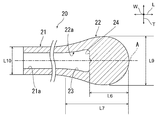
- the capillary 20 for encapsulating a phosphor includes a capillary body 21 and a sealing portion 22.
- the capillary body 21 is composed of a portion of the glass capillary 10 that has not melted.
- the capillary body 21 has an elongated shape whose outer diameter in the cross section is elongated in the width direction W. Specifically, the capillary body 21 is a rectangular tube. The thickness of the capillary body 21 is substantially constant.
- the sealing portion 22 is a portion formed by the melted end portion 10 ⁇ / b> A of the glass capillary tube 10.
- the sealing portion 22 seals one end portion of the capillary body 21.
- the dimension (outer diameter) in the width direction W decreases toward the front end side as shown in FIG. 9, while the dimension in the thickness direction T perpendicular to the width direction W as shown in FIG. It is formed so that (outer diameter) once becomes larger toward the tip side and then becomes smaller.
- L9 is preferably about 0.08 mm to 9 mm.
- the sealing portion 22 has a side wall portion 23 and a bottom wall portion 24 that constitute a concave portion 22 a that opens to the through hole 21 a of the capillary body 21.
- the side wall portion 23 gradually widens toward the distal end side when viewed from the width direction W, while the bottom wall portion 23 is bottom when viewed from the thickness direction T as shown in FIG.
- the distance between the opposing portions of the wall portion 24 gradually decreases toward the tip side.
- At least a part of the bottom wall portion 24 is formed in a planar shape whose normal direction is parallel to the central axis A of the capillary body 21.
- the portion excluding the central portion of the bottom wall portion 24 and the connection portion with the side wall portion 23 is formed in a planar shape whose normal direction is parallel to the central axis A of the capillary body 21.
- the center part of the bottom wall part 24 is formed so that the normal line direction faces the central axis A side. In other words, when viewed from each of the width direction W and the thickness direction T, it is formed so as to become narrower toward the tip side.
- the bottom wall portion 24 is located on the center side of the portion where the dimension in the thickness direction T of the sealing portion 22 is maximum.
- the distance L6 from the bottom wall portion 24 to the tip of the sealing portion 22 is preferably in the range of 0.2 to 0.8 times the length L7 of the sealing portion 22.
- L6 is preferably about 0.1 mm to 4.0 mm.
- L7 is preferably about 0.13 mm to 10 mm.
- L8 (see FIG. 9) is preferably about 0.1 mm to 4.0 mm.
- the inner wall and the outer wall of the sealing portion 22 of the phosphor encapsulating capillary 20 are substantially non-parallel. For this reason, the light from the phosphor encapsulated in the phosphor encapsulating capillary 20 is easily reflected by either the inner wall or the outer wall of the sealing portion 22. Therefore, the fluorescence is less likely to leak from the sealing portion 22, and the emission rate of the fluorescence from the capillary body 21 is increased. Therefore, a high-brightness backlight can be realized by configuring an edge light type backlight using the phosphor encapsulating capillary 20 manufactured in the present embodiment.
- the open end is also sealed in the same procedure as described above, thereby obtaining the more prominent effects described above. be able to.
- the present invention is not limited to this.
- the recess 25 may be formed at the tip of the sealing portion 22 as shown in FIG. 10 by shortening the heating time or lowering the heating temperature.
- the phosphor is injected from the opening of the capillary 20 for encapsulating the phosphor.
- the method for injecting the phosphor is not particularly limited, but when the phosphor is in a liquid state or the phosphor fine particles are dispersed in the liquid, for example, the inside of the capillary 20 for encapsulating the phosphor is decompressed. In this state, it is preferable to use a method of supplying the phosphor into the capillary 20 for encapsulating the phosphor.
- the opening of the capillary tube 20 for encapsulating the phosphor is sealed by a method substantially similar to the sealing method performed when manufacturing the capillary tube 20 for encapsulating the phosphor.
- the wavelength conversion member with which the fluorescent substance was enclosed in the capillary with which both ends were sealed can be completed.
- each end of the capillary tube of the wavelength conversion member according to the present embodiment has the structure shown in FIGS.
- the capillary of the wavelength conversion member has an elongated shape whose outer shape in the cross section is elongated in the width direction.
- the capillary tube has a straight tubular capillary body with a substantially constant thickness, a first sealing portion that seals one end portion of the capillary body, and the other end portion of the capillary body.
- a second sealing portion is such that the dimension in the width direction decreases toward the tip side, while the dimension in the thickness direction perpendicular to the width direction decreases once the dimension in the thickness direction increases toward the tip side. Is formed.
- the wavelength conversion member according to the present embodiment a high-luminance edge light type backlight can be realized.
- a glass capillary tube 10 having L3 of 0.2 mm, L4 of 0.6 mm, L1 of 0.1 mm, L2 of 0.5 mm, and a wall thickness t of 0.05 mm was formed by a stretch molding method.
- the end portion of the glass capillary tube 10 was heated using an infrared laser until the end portion was melted and sealed by integration, thereby producing the capillary 20 for encapsulating the phosphor.
- FIG. 11 shows a plan photograph of the produced phosphor encapsulating capillary 20 and
- FIG. 12 shows a side photograph thereof.
- the phosphors are similarly encapsulated in the phosphor encapsulating capillaries prepared in each of the above Examples and Comparative Examples, and the phosphor encapsulating capillaries are irradiated with blue light on the side surfaces of the phosphor encapsulating capillaries using LEDs.
- the intensity of fluorescence leaking from the end of the tube was measured.
- the average brightness of the fluorescence leaked from the end of the phosphor encapsulating capillary produced in the example was about 0 of the average brightness of the fluorescence leaked from the end of the phosphor encapsulating capillary prepared in the comparative example. 34 times. From this result, it can be seen that the fluorescent light is less likely to leak from the sealing portion in the example.
- Second Embodiment (Manufacturing method of capillary for encapsulating phosphor) First, a method for manufacturing a phosphor-encapsulating capillary in the present embodiment will be described.
- the phosphor-encapsulating capillary described here has a first end located on the first side in the length direction and a second end located on the second side in the length direction. Is a phosphor-encapsulating capillary tube in which the phosphor is encapsulated from the first end.
- a glass capillary tube 10 in which each of the first and second end portions 10A and 10B shown in FIGS. 13 to 15 is opened is prepared.
- the glass capillary tube 10 has an elongated shape whose outer shape in a transverse section (that is, a section along the width direction W and the thickness direction T) is elongated in the width direction W.
- the glass capillary tube 10 is formed in a rectangular tube whose outer shape in a cross section is a rectangular shape.
- square tube means a straight tube whose outer shape and inner shape are rectangular when viewed from the length direction L.
- the “rectangle” includes a rectangle whose corners are chamfered or rounded.
- the glass capillary tube 10 has flat plate-like first and second side wall portions 10a, 10b facing each other and flat plate-like third and fourth side wall portions 10c, 10d facing each other.
- a prismatic through hole 10e is defined by the first to fourth side wall portions 10a to 10d.
- the dimensions of the glass capillary tube 10 are not particularly limited.
- the wall thickness t (see FIG. 14) of the glass capillary tube 10 can be, for example, about 0.01 mm to 1.0 mm.
- the inner diameter L1 along the thickness direction T of the glass capillary tube 10 can be set to, for example, about 0.05 mm to 1.0 mm.
- the outer diameter L3 along the thickness direction T of the glass capillary tube 10 can be, for example, about 0.07 mm to 3.0 mm.
- the inner diameter L2 along the width direction W of the glass capillary tube 10 can be, for example, about 0.1 mm to 2.0 mm.
- the outer diameter L4 along the width direction W of the glass capillary tube 10 can be, for example, about 0.12 mm to 4.0 mm.
- L1 / L2 and L3 / L4 can be set to about 0.025 to 0.5, for example.
- t / L1 can be set, for example, to about 0.01 to 2.0.
- t / L2 can be set to, for example, about 0.005 to 2.0.
- the dimension L5 along the length direction L of the glass capillary tube 10 can be, for example, about 10 mm to 100 mm.
- the type of glass constituting the glass capillary tube 10 is not particularly limited.
- the glass capillary tube 10 may be made of, for example, silicate glass, borate glass, phosphate glass, borosilicate glass, borophosphate glass, or the like.
- the glass capillary tube 10 is preferably formed of silicate glass or borosilicate glass from the viewpoint of increasing the rigidity of the manufactured phosphor encapsulation capillary.
- the softening temperature (At) of the glass capillary tube 10 is not particularly limited.
- the softening temperature (At) of the glass capillary tube 10 can be set to about 700 ° C. to 950 ° C., for example.
- This sealing step includes a first heating step and a second heating step.
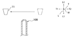
- the first heating process is performed. Specifically, as shown in FIG. 16, on the L2 side in the length direction L of the second end portion 10B, the heating means 11 is caused to cross over the second end portion 10B. More specifically, in the present embodiment, the heating unit 11 is crossed over the second end portion 10B from the T1 side in the thickness direction T toward the T2 side. Thereby, the second end portion 10B is heated and softened. Then, the second end portion 10B is sealed.
- a second heating step is performed. Specifically, as shown in FIG. 18, on the L2 side in the length direction L of the second end portion 10B, the heating means 11 is placed on the second end portion 10B opposite to the first heating step. Cross in the direction. That is, the heating means 11 is traversed on the second end portion 10B from the T2 side in the thickness direction T toward the T1 side. Thereby, as shown in FIG. 19, the sealed second end portion 10B is heated again to adjust the shape of the second end portion 10B.
- the moving direction of the heating unit is not limited to the thickness direction.
- the heating means may be moved in the width direction, or may be moved in a direction inclined in the width direction and the thickness direction.
- first and second heating steps are performed once.
- the first and second heating steps may be repeated a plurality of times.
- the heating means 11 is not particularly limited as long as it can heat the glass capillary tube 10.
- the heating means 11 can be comprised by a laser irradiation apparatus, a burner, etc., for example.
- a laser irradiation apparatus is used as the heating unit 11.
- the shape of the laser light spot 11S is an elongated shape elongated in the width direction W of the glass capillary tube 10. It is.
- the time during which the second end portion 10B is irradiated with laser light is in the width direction W perpendicular to the thickness direction T, which is the moving direction of the heating means 11. It is assumed to be constant. That is, each of the one end, the center, and the other end in the width direction W of the second end 10B is irradiated with the laser beam for substantially the same time in each of the first and second heating steps.
- the Rukoto is assumed to be constant.
- the heating temperature by the heating means 11 in the first and second heating steps and the moving speed of the heating means 11 are set to values such that the second end portion 10B does not become thicker than other portions of the glass capillary tube 10. Is set.
- the laser light output is adjusted to about 5 W to 30 W, and the moving speed is adjusted to 1 mm to 50 mm / min.
- the first end 20A located on the L1 side in the length direction L of the capillary 20 for encapsulating the phosphor is open.
- the first end 20A is composed of the first end 10A.
- the 2nd end part 20B located in the L2 side of the length direction L of the capillary 20 for fluorescent substance enclosure is sealed.
- the second end 20B is formed from the second end 10B.
- the capillary tube 20 for encapsulating the phosphor has an elongated shape with a transverse cross section elongated in the width direction W, specifically, a rectangular shape.
- the phosphor 30 is injected into the capillary 20 for encapsulating the phosphor.
- the method for injecting the phosphor 30 is not particularly limited. However, when the phosphor 30 is in a liquid state or the phosphor fine particles are dispersed in the liquid, for example, the pressure inside the capillary 20 for encapsulating the phosphor is reduced. In this state, it is preferable to use a method of supplying the phosphor into the phosphor encapsulating capillary 20.
- the type of the phosphor 30 to be injected in this step is not particularly limited.
- the phosphor may contain, for example, an inorganic phosphor powder.
- an inorganic phosphor that emits blue visible light (fluorescence having a wavelength of 440 nm to 480 nm) when irradiated with ultraviolet to near ultraviolet excitation light having a wavelength of 300 nm to 440 nm, Sr 5 (PO 4 ) 3 Cl: Eu 2+ , (Sr, Ba) MgAl 10 O 17 : Eu 2+ and the like.
- inorganic phosphors that emit green visible light (fluorescence having a wavelength of 500 nm to 540 nm) when irradiated with ultraviolet to near ultraviolet excitation light having a wavelength of 300 nm to 440 nm include SrAl 2 O 4 : Eu 2+ , SrGa 2 S 4 : Eu ⁇ 2+> etc. are mentioned.
- Specific examples of inorganic phosphors that emit green visible light (fluorescence having a wavelength of 500 nm to 540 nm) when irradiated with blue excitation light having a wavelength of 440 nm to 480 nm include SrAl 2 O 4 : Eu 2+ and SrGa 2 S 4 : Eu. 2+ and the like.
- a specific example of the inorganic phosphor that emits yellow visible light (fluorescence having a wavelength of 540 nm to 595 nm) when irradiated with excitation light having a wavelength of 300 nm to 440 nm is ZnS: Eu 2+ .
- the inorganic phosphor that emits yellow visible light (fluorescence having a wavelength of 540 nm to 595 nm) when irradiated with blue excitation light having a wavelength of 440 nm to 480 nm Y 3 (Al, Gd) 5 O 12 : Ce 2+, etc. Is mentioned.
- the inorganic phosphor that emits red visible light (fluorescence with a wavelength of 600 nm to 700 nm) when irradiated with ultraviolet to near ultraviolet excitation light having a wavelength of 300 nm to 440 nm include Gd 3 Ga 4 O 12 : Cr 3+ , CaGa 2 S 4 : Mn 2+ and the like.
- Specific examples of the inorganic phosphor that emits red visible light (fluorescence having a wavelength of 600 nm to 700 nm) when irradiated with blue excitation light having a wavelength of 440 nm to 480 nm include Mg 2 TiO 4 : Mn 4+ , K 2 SiF 6 : Mn 4+ and the like.
- the inorganic phosphor powder may be, for example, a quantum dot.
- the quantum dot emits light having a wavelength different from that of the excitation light when the excitation light is incident.
- the wavelength of the light emitted from the quantum dot depends on the particle diameter of the quantum dot. That is, the wavelength of the light obtained by changing the particle diameter of the quantum dots can be adjusted. For this reason, the particle diameter of a quantum dot is made into the particle diameter according to the wavelength of the light to obtain. Quantum dots generally tend to deteriorate due to contact with oxygen.
- Quantum dots having a particle diameter of about 2 nm to 10 nm can be used, for example.
- a quantum dot that emits blue visible light (fluorescence having a wavelength of 440 nm to 480 nm) when irradiated with excitation light having a wavelength of 300 to 440 nm the particle diameter is 2.0 nm to 3.0 nm. CdSe microcrystals and the like.
- quantum dots that emit green visible light (fluorescence with a wavelength of 500 nm to 540 nm) when irradiated with ultraviolet to near ultraviolet excitation light with a wavelength of 300 to 440 nm or blue excitation light with a wavelength of 440 to 480 nm include particle diameters.
- CdSe microcrystals having a thickness of about 3.0 nm to 3.3 nm.
- quantum dots that emit yellow visible light (fluorescence with a wavelength of 540 nm to 595 nm) when irradiated with ultraviolet to near ultraviolet excitation light with a wavelength of 300 to 440 nm or blue excitation light with a wavelength of 440 to 480 nm include particle diameters.
- Specific examples of quantum dots that emit red visible light (fluorescence having a wavelength of 600 nm to 700 nm) when irradiated with ultraviolet to near ultraviolet excitation light having a wavelength of 300 to 440 nm or blue excitation light having a wavelength of 440 to 480 nm include particle diameters.
- one or more types of phosphors 30 may be encapsulated in accordance with the wavelength range of excitation light and the color to be emitted. For example, if you want to obtain white light with excellent color rendering properties by irradiating ultraviolet to near ultraviolet excitation light, blue, green and red visible light (fluorescence) is emitted by irradiating ultraviolet to near ultraviolet excitation light. What is necessary is just to mix and use the fluorescent substance 30 to emit. In addition, when irradiating blue excitation light and obtaining white light with excellent color rendering properties, the phosphor 30 emitting green and red visible light (fluorescence) is mixed by irradiating the blue excitation light. Use it.
- the sealing process of the first end portion 20A includes a third heating process and a fourth heating process.
- a third heating step is performed. Specifically, as shown in FIG. 22, the heating means 11 is crossed over the first end 20A on the L1 side in the length direction L of the first end 20A. More specifically, in this embodiment, the heating means 11 is traversed on the first end 20A from the T1 side in the thickness direction T toward the T2 side. Thereby, the first end 20A is heated and softened. Then, the first end 20A is sealed.
- a fourth heating step is performed. Specifically, as shown in FIG. 23, on the L1 side in the length direction L of the first end portion 20A, the heating means 11 is placed on the first end portion 20A in the opposite direction to the third heating step. Cross in the direction. That is, the heating means 11 is traversed on the first end 20A from the T2 side in the thickness direction T toward the T1 side. Thereby, as shown in FIG. 24, the sealed first end 20A is heated again, and the shape of the first end 20A is adjusted.
- the moving direction of the heating unit is not limited to the thickness direction.
- the heating means may be moved in the width direction, or may be moved in a direction inclined in the width direction and the thickness direction.
- the present invention is not limited to this.
- the third and fourth heating steps may be repeated a plurality of times.
- the heating means 11 can be the same as that used in the first and second heating steps, but is different between the first and second heating steps and the third and fourth heating steps.
- a heating means may be used.
- the heating temperature by the heating means 11 and the moving speed of the heating means 11 in the third and fourth heating steps are such that the first end portion 20A is not thicker than the other portions of the phosphor encapsulation capillary 20. It is set to a valid value.
- the wavelength conversion member 13 shown in FIG. 25 is manufactured by the above process.
- the wavelength conversion member 13 has a glass capillary tube 12 in which both end portions 12A and 12B are sealed.
- the thickness of both end portions 12A and 12B is equal to or less than the thickness of the central portion 12C of the glass capillary tube 12.
- the outer shape in the cross section of the central portion 12C is an elongated shape, specifically a rectangular shape. Inside the glass capillary tube 12, a phosphor 30 is enclosed.
- the elongated glass capillary tube 10 is used.
- the external shape in a cross section is an elongate shape, More specifically, it is a rectangular shape,
- the wavelength conversion member 13 which can be arrange
- the second end 10B and the first end 20A are sealed by two heating steps.
- the heating means 11 is traversed over the second or first end portions 10B and 20A from the T1 side to the T2 side.
- laser light is irradiated to the portions 10B2 and 20A2 on the T2 side from the time for which the T1 side portions 10B1 and 20A1 of the second or first end portions 10B and 20A are irradiated with the laser light.
- the time is longer.
- the temperature of part 10B2, 20A2 becomes higher than part 10B1, 20A1. Therefore, as shown in FIGS. 18 and 23, the second and first end portions 10B and 20A have an asymmetric shape.
- the temperature of the T1 side portion is higher than the T2 side portion of the second or first end 10B, 20A. For this reason, the softening of the portion on the T1 side is promoted, and as shown in FIGS. 19 and 24, the shapes of the second or first end portions 10B and 20A are symmetrical.
- the shape of the both ends of wavelength conversion member 13 obtained is shown. While being close to a target shape, the thickness of both ends can be suppressed. For example, the thickness of both ends can be equal to or less than the thickness of other portions. Therefore, according to the method of the present embodiment, the wavelength conversion member 13 that can be disposed closer to the light guide can be manufactured.
- the end portion is sealed by the heating means arranged to face the end portion without scanning the heating means.
- the thickness of the sealed end portion becomes thicker than other portions. Therefore, the wavelength conversion member manufactured by such a sealing method cannot be disposed sufficiently close to the light guide.
- the heating means 11 is moved in the thickness direction T in the first to fourth heating steps.
- a laser irradiation device is used as the heating means 11.
- a laser irradiation device is used as the heating means 11.
- a laser irradiation apparatus in which the shape of the spot 11S is circular may be used.
- the time during which the end portions 10B and 20A are irradiated with the laser light varies in the width direction W.
- the laser beam is irradiated to the central portion in the width direction W of the end portions 10B and 20A for a long time, and the laser beam is irradiated to the end portions only for a short time.
- the symmetry of the shapes of the sealed end portions 10B and 20A is lowered, the central portion is excessively heated, and the thickness of the central portion is sometimes increased.
- the shape of the spot 11S is an elongated shape, and variations in the width direction W of the time during which the end portions 10B and 20A are irradiated with laser light are suppressed. Therefore, it can suppress more effectively that the thickness of a center part becomes thick. As a result, the wavelength conversion member 13 that can be disposed closer to the light guide can be manufactured.
- the intensity of the laser beam is the center of the laser beam spot 11S in the width direction W of the glass capillary tube 10 as shown in FIG. It is preferable to use a laser irradiation apparatus that irradiates laser light that is substantially constant. In this case, by arranging the plurality of glass capillaries 10 along the width direction W and performing laser light irradiation, the ends of the plurality of glass capillaries 10 can be suitably sealed by the same heating process.
- the method for manufacturing a capillary for encapsulating a phosphor described in the first embodiment can be suitably applied to the manufacture of the capillary for encapsulating a phosphor described in the second embodiment.
- the method for manufacturing a phosphor-encapsulating capillary described in the second embodiment can also be suitably applied to the manufacture of the phosphor-encapsulating capillary described in the first embodiment.
- each of the inner shape and the outer shape in the cross section of the glass capillary tube 10 may be oval.
- each of the inner shape and the outer shape in the cross section of the glass capillary tube may be elliptical.
- the inner shape in the cross section of the glass capillary tube 10 is substantially rectangular, while the outer shape may be oval or elliptical.
- the inner shape in the cross section of the glass capillary tube 10 may be a substantially rectangular shape, and the outer shape may be a substantially rectangular shape in which two sides facing in the width direction bulge outward. .
Landscapes
- Chemical & Material Sciences (AREA)
- Physics & Mathematics (AREA)
- Engineering & Computer Science (AREA)
- Materials Engineering (AREA)
- Organic Chemistry (AREA)
- Nonlinear Science (AREA)
- Mathematical Physics (AREA)
- Crystallography & Structural Chemistry (AREA)
- General Physics & Mathematics (AREA)
- Optics & Photonics (AREA)
- Led Device Packages (AREA)
- Vessels And Coating Films For Discharge Lamps (AREA)
Abstract
Description
図1は、ガラス毛細管の略図的斜視図である。図2は、図1の線II-IIにおける略図的断面図である。図3は、図1の線III-IIIにおける略図的断面図である。
まず、蛍光体封入用毛細管20の開口から、蛍光体を注入する。蛍光体の注入方法は特に限定されないが、蛍光体が、液体状であったり、蛍光体微粒子が液体中に分散したものであったりする場合は、例えば、蛍光体封入用毛細管20内を減圧にした状態で蛍光体封入用毛細管20内に蛍光体を供給する方法を用いることが好ましい。
まず、延伸成形法により、L3が0.2mm、L4が0.6mm、L1が0.1mm、L2が0.5mmで肉厚tが、0.05mmのガラス毛細管10を成形した。次に、端部が融解し、一体化することにより封止されるまで、ガラス毛細管10の端部を赤外線レーザーを用いて加熱して、蛍光体封入用毛細管20を作製した。作製した蛍光体封入用毛細管20の平面写真を図11に示し、側面写真を図12に示す。
上記実施例において作製したガラス毛細管10の端部にガラス毛細管10と同様の組成を有するガラスからなるガラス平板を融着させることにより、端部が平板状である蛍光体封入用毛細管を作製した。
(蛍光体封入用毛細管の製造方法)
まず、本実施形態における蛍光体封入用毛細管の製造方法について説明する。ここで説明する蛍光体封入用毛細管は、長さ方向の第1の側に位置する第1の端部が開口している一方、長さ方向の第2の側に位置する第2の端部が封止されており、第1の端部から蛍光体が封入される蛍光体封入用毛細管である。
まず、図13~図15に示す、第1及び第2の端部10A,10Bのそれぞれが開口したガラス毛細管10を用意する。ガラス毛細管10は、横断面(すなわち、幅方向W及び厚み方向Tに沿った断面)における外形が幅方向Wに細長い細長形状を有する。具体的には、本実施形態では、ガラス毛細管10は、横断面における外形が矩形状である角管状に形成されている。ここで、「角管」とは、長さ方向Lから視た際に、外形及び内形のそれぞれが矩形状である直管を意味する。「矩形」には、角部が面取り状またはR面取り状である矩形が含まれるものとする。
次に、図16~図19を参照しながら、ガラス毛細管10の第2の端部10Bを封止する工程について説明する。
上記第2の端部10Bの封止工程を行うことにより、図20に示す蛍光体封入用毛細管20を作製することができる(用意工程)。
次に、図21に示すように、蛍光体封入用毛細管20内に蛍光体30を注入する。この蛍光体30の注入方法は特に限定されないが、蛍光体30が、液体状であったり、蛍光体微粒子が液体中に分散したものである場合は、例えば、蛍光体封入用毛細管20内を減圧にした状態で蛍光体封入用毛細管20内に蛍光体を供給する方法を用いることが好ましい。
次に、蛍光体30が注入された蛍光体封入用毛細管20の第1の端部20Aを封止する工程を行う。この工程は、上記の第2の端部10Bの封止工程と実質的に同様の工程である。
以上の工程により、図25に示す波長変換部材13が製造される。波長変換部材13は、両端部12A,12Bが封止されたガラス毛細管12を有する。両端部12A,12Bの太さは、ガラス毛細管12の中央部分12Cの太さ以下である。中央部分12Cの横断面における外形は、細長形状、詳細には矩形状である。ガラス毛細管12の内部には、蛍光体30が封入されている。
第1の実施形態において説明した蛍光体封入用毛細管の製造方法は、第2の実施形態において説明した蛍光体封入用毛細管の製造にも好適に適用することができる。同様に、第2の実施形態において説明した蛍光体封入用毛細管の製造方法は、第1の実施形態において説明した蛍光体封入用毛細管の製造にも好適に適用することができる。
10A,10B…ガラス毛細管の端部
10A1…断面円状部分
10a…第1の側壁部
10b…第2の側壁部
10c…第3の側壁部
10d…第4の側壁部
10e…貫通孔
11…加熱手段
11S…スポット
13…波長変換部材
20…蛍光体封入用毛細管
20A…蛍光体封入用毛細管の第1の端部
20B…蛍光体封入用毛細管の第2の端部
21…毛細管本体
21a…貫通孔
22…封止部
22a…凹部
23…側壁部
24…底壁部
25…窪み
Claims (24)
- 一方側端部が封止されている一方、他方側端部が開口しており、前記他方側端部から蛍光体が封入される蛍光体封入用毛細管の製造方法であって、
横断面における外形が幅方向に細長い細長形状のガラス毛細管の一方側端部が融解し、一体化することにより封止されるまで前記ガラス毛細管の一方側端部を加熱する加熱工程を備える、蛍光体封入用毛細管の製造方法。 - 前記ガラス毛細管として、角管状のガラス毛細管を使用する、請求項1に記載の蛍光体封入用毛細管の製造方法。
- 前記加熱工程において、前記ガラス毛細管の一方側端部の幅方向における寸法が先端側に向かって小さくなる一方、前記ガラス毛細管の一方側端部の幅方向に垂直な厚み方向における寸法は、先端側に向かって一旦大きくなった後に小さくなるように前記ガラス毛細管の一方側端部を加熱する、請求項1または2に記載の蛍光体封入用毛細管の製造方法。
- 前記加熱工程において、前記ガラス毛細管の一方側端部の厚み方向における最大寸法が、前記ガラス毛細管の一方側端部を除く部分の厚み方向に沿った寸法の1.1倍~3.0倍となるように前記ガラス毛細管の一方側端部を加熱する、請求項1~3のいずれか一項に記載の蛍光体封入用毛細管の製造方法。
- 前記加熱工程において、前記ガラス毛細管の一方側端部の幅方向及び幅方向に垂直な厚み方向のそれぞれにおける寸法が先端側に向かって小さくなるように前記ガラス毛細管の一方側端部を加熱する、請求項1または2に記載の蛍光体封入用毛細管の製造方法。
- 前記加熱工程は、
加熱手段を前記ガラス毛細管の一方側端部の上を横切らせることにより前記ガラス毛細管の一方側端部を加熱して封止する第1の加熱工程と、
前記加熱手段を前記ガラス毛細管の一方側端部の上を、前記第1の加熱工程とは逆方向に横切らせることにより前記ガラス毛細管の一方側端部を再度加熱する第2の加熱工程と、
を含む、請求項1~5のいずれか一項に記載の蛍光体封入用毛細管の製造方法。 - 前記第1及び第2の加熱工程において、前記ガラス毛細管の一方側端部が前記ガラス毛細管の前記ガラス毛細管の一方側端部以外の部分よりも太くならないように前記加熱手段による加熱温度及び前記加熱手段の移動速度を設定する、請求項6に記載の蛍光体封入用毛細管の製造方法。
- 前記第1及び第2の加熱工程において、前記加熱手段を、前記ガラス毛細管の厚み方向に移動させる、請求項6または7に記載の蛍光体封入用毛細管の製造方法。
- 前記加熱手段として、レーザー照射装置を用い、前記レーザー照射装置により前記ガラス毛細管の一方側端部にレーザーを照射することにより、前記ガラス毛細管の一方側端部を加熱する、請求項6~8のいずれか一項に記載の蛍光体封入用毛細管の製造方法。
- 前記レーザー照射装置として、レーザー光のスポット形状が、前記ガラス毛細管の幅方向に細長い細長形状であるレーザー照射装置を用いる、請求項9に記載の蛍光体封入用毛細管の製造方法。
- 前記レーザー照射装置として、前記第1及び第2の加熱工程において前記ガラス毛細管の一方側端部に対して前記レーザー光が照射されている時間が、前記レーザー照射装置の移動方向と垂直な方向において一定となるようなスポット形状のレーザー光を照射するレーザー照射装置を用いる、請求項9または10に記載の蛍光体封入用毛細管の製造方法。
- 前記レーザー照射装置として、レーザー光の強度が、前記ガラス毛細管の幅方向における前記レーザー光のスポットの中央部において略一定であるレーザー光を照射するレーザー照射装置を用いる、請求項9~11のいずれか一項に記載の蛍光体封入用毛細管の製造方法。
- 前記加熱手段として、バーナーを用いる、請求項6~8のいずれか一項に記載の蛍光体封入用毛細管の製造方法。
- 請求項1~13のいずれか一項に記載の蛍光体封入用毛細管の製造方法により製造された蛍光体封入用毛細管。
- 一方側端部が封止されている一方、他方側端部が開口しており、前記他方側端部から蛍光体が封入される蛍光体封入用毛細管であって、
横断面における外形が幅方向に細長い細長形状を有し、肉厚が略一定の直管状の毛細管本体と、
前記毛細管本体の一方側端部を封止している封止部と、
を備え、
前記封止部は、幅方向における寸法が先端側に向かって小さくなる一方、幅方向に垂直な厚み方向における寸法が先端側に向かって一旦大きくなった後に小さくなるように形成されている、蛍光体封入用毛細管。 - 封止部の厚み方向における最大寸法は、毛細管本体の厚み方向に沿った寸法の1.1倍~3.0倍である、請求項15に記載の蛍光体封入用毛細管。
- 一方側端部が封止されている一方、他方側端部が開口しており、前記他方側端部から蛍光体が封入される蛍光体封入用毛細管であって、
横断面における外形が幅方向に細長い細長形状を有し、肉厚が略一定の直管状の毛細管本体と、
前記毛細管本体の一方側端部を封止している封止部と、
を備え、
前記封止部は、幅方向及び幅方向に対して垂直な厚み方向のそれぞれにおける寸法が先端側に向かって小さくなるように形成されている、蛍光体封入用毛細管。 - 前記封止部は、前記毛細管本体の貫通孔に開口している凹部を構成している側壁部及び底壁部を有し、
前記底壁部の少なくとも一部は、法線方向が前記毛細管本体の中心軸と平行な平面状に形成されている、請求項15~17のいずれか一項に記載の蛍光体封入用毛細管。 - 前記底壁部の中央部は、法線方向が前記毛細管本体の中心軸側を向くように形成されている、請求項18に記載の蛍光体封入用毛細管。
- 前記毛細管本体の中心軸の延びる方向において、前記底壁部は、前記封止部の前記厚み方向における寸法が最大となる部分よりも中央側に位置している、請求項18または19に記載の蛍光体封入用毛細管。
- 前記毛細管本体は、角管状に形成されている、請求項15~20のいずれか一項に記載の蛍光体封入用毛細管。
- 両端部が封止された毛細管と、
前記毛細管内に封入された蛍光体と、
を備える波長変換部材であって、
前記毛細管は、
横断面における外形が幅方向に細長い細長形状を有し、肉厚が略一定の直管状の毛細管本体と、
前記毛細管本体の一方側端部を封止している第1の封止部と、
前記毛細管本体の他方側端部を封止している第2の封止部と、
を備え、
前記第1及び第2の封止部の少なくとも一方は、幅方向における寸法が先端側に向かって小さくなる一方、幅方向に垂直な厚み方向における寸法が先端側に向かって一旦大きくなった後に小さくなるように形成されている、波長変換部材。 - 両端部が封止された毛細管と、
前記毛細管内に封入された蛍光体と、
を備える波長変換部材であって、
前記毛細管は、
横断面における外形が幅方向に細長い細長形状を有し、肉厚が略一定の直管状の毛細管本体と、
前記毛細管本体の一方側端部を封止している第1の封止部と、
前記毛細管本体の他方側端部を封止している第2の封止部と、
を備え、
前記第1及び第2の封止部の少なくとも一方は、幅方向及び幅方向に対して垂直な厚み方向のそれぞれにおける寸法が先端側に向かって小さくなるように形成されている、波長変換部材。 - 請求項14~21のいずれか一項に記載の蛍光体封入用毛細管の他方側端部から前記蛍光体を注入する工程と、
前記蛍光体が注入された蛍光体封入用毛細管の他方側端部を封止する第1の端部封止工程と、
を備える、波長変換部材の製造方法。
Priority Applications (3)
| Application Number | Priority Date | Filing Date | Title |
|---|---|---|---|
| CN201180036379.6A CN103025670B (zh) | 2010-07-28 | 2011-07-11 | 荧光体封入用毛细管的制造方法、荧光体封入用毛细管、波长变换部件和波长变换部件的制造方法 |
| US13/805,058 US9365445B2 (en) | 2010-07-28 | 2011-07-11 | Method for producing phosphor-encapsulating capillary tube, phosphor-encapsulating capillary tube, wavelength-converting member, and method for producing wavelength-converting member |
| KR1020137000315A KR101808362B1 (ko) | 2010-07-28 | 2011-07-11 | 형광체 봉입용 모세관의 제조 방법, 형광체 봉입용 모세관, 파장 변환 부재 및 파장 변환 부재의 제조 방법 |
Applications Claiming Priority (4)
| Application Number | Priority Date | Filing Date | Title |
|---|---|---|---|
| JP2010-168941 | 2010-07-28 | ||
| JP2010168941 | 2010-07-28 | ||
| JP2011-028500 | 2011-02-14 | ||
| JP2011028500 | 2011-02-14 |
Publications (1)
| Publication Number | Publication Date |
|---|---|
| WO2012014663A1 true WO2012014663A1 (ja) | 2012-02-02 |
Family
ID=45529880
Family Applications (1)
| Application Number | Title | Priority Date | Filing Date |
|---|---|---|---|
| PCT/JP2011/065765 Ceased WO2012014663A1 (ja) | 2010-07-28 | 2011-07-11 | 蛍光体封入用毛細管の製造方法、蛍光体封入用毛細管、波長変換部材及び波長変換部材の製造方法 |
Country Status (5)
| Country | Link |
|---|---|
| US (1) | US9365445B2 (ja) |
| KR (1) | KR101808362B1 (ja) |
| CN (1) | CN103025670B (ja) |
| TW (1) | TWI525290B (ja) |
| WO (1) | WO2012014663A1 (ja) |
Cited By (2)
| Publication number | Priority date | Publication date | Assignee | Title |
|---|---|---|---|---|
| US20170362501A1 (en) * | 2015-04-10 | 2017-12-21 | Nippon Electric Glass Co., Ltd. | Wavelength conversion material |
| JP2020032376A (ja) * | 2018-08-30 | 2020-03-05 | 株式会社シン・コーポレイション | 毛細管封止具及び微量試料採取器具 |
Families Citing this family (10)
| Publication number | Priority date | Publication date | Assignee | Title |
|---|---|---|---|---|
| US9864121B2 (en) * | 2011-11-22 | 2018-01-09 | Samsung Electronics Co., Ltd. | Stress-resistant component for use with quantum dots |
| KR20150104242A (ko) | 2014-03-04 | 2015-09-15 | 삼성디스플레이 주식회사 | 백라이트 어셈블리 및 그를 포함하는 표시장치 |
| US10230022B2 (en) | 2014-03-13 | 2019-03-12 | General Electric Company | Lighting apparatus including color stable red emitting phosphors and quantum dots |
| KR20150110847A (ko) | 2014-03-20 | 2015-10-05 | 삼성디스플레이 주식회사 | 양자점 충진 튜브 및 이를 포함하는 표시 장치 |
| DE102015002456A1 (de) * | 2015-02-23 | 2016-08-25 | Schott Schweiz Ag | Vorrichtung und Verfahren zur Formung von Glaskörpern |
| CN105185890A (zh) * | 2015-08-10 | 2015-12-23 | 深圳市华星光电技术有限公司 | Led光源结构及其封装方法 |
| CN105140377A (zh) * | 2015-08-10 | 2015-12-09 | 深圳市华星光电技术有限公司 | 量子点玻璃盒及其制备方法和应用 |
| DE102015114175A1 (de) * | 2015-08-26 | 2017-03-16 | Osram Opto Semiconductors Gmbh | Verfahren zur Herstellung von lichtemittierenden Halbleiterbauteilen und lichtemittierendes Halbleiterbauteil |
| DK3707103T3 (da) * | 2017-11-06 | 2022-08-08 | Efacec Engenharia E Sist S A | Fremgangsmåde til forsegling af huller i glas samt herved opnåede genstande |
| CA3161516A1 (en) | 2019-12-17 | 2021-06-24 | Philip Thomas FROHLICH | Methods of treating iga nephropathy with atrasentan |
Citations (3)
| Publication number | Priority date | Publication date | Assignee | Title |
|---|---|---|---|---|
| JPH06263465A (ja) * | 1993-03-09 | 1994-09-20 | Nippon Electric Glass Co Ltd | ガラス管端の封止方法 |
| JP2007157599A (ja) * | 2005-12-07 | 2007-06-21 | Sanken Electric Co Ltd | 放電管及びバックライト装置 |
| JP2007225462A (ja) * | 2006-02-24 | 2007-09-06 | Fuchu Giken:Kk | ガラス毛細管への液状試料の封入手段及びこの封入手段による液状試料の測定分析機器用ガラスカプセル |
Family Cites Families (5)
| Publication number | Priority date | Publication date | Assignee | Title |
|---|---|---|---|---|
| US3119176A (en) * | 1961-05-24 | 1964-01-28 | Honeywell Regulator Co | Method of making a capillary tube fluid filled transmission system |
| JP3705914B2 (ja) | 1998-01-27 | 2005-10-12 | 三菱電機株式会社 | 面放電型プラズマディスプレイパネル及びその製造方法 |
| JP2007025285A (ja) | 2005-07-15 | 2007-02-01 | Harison Toshiba Lighting Corp | 液晶用バックライト |
| JP4232205B2 (ja) * | 2006-02-08 | 2009-03-04 | 日本電気硝子株式会社 | 光ファイバ固定用毛細管及び光学部品用接続構造 |
| JP2009193676A (ja) * | 2008-02-12 | 2009-08-27 | Harison Toshiba Lighting Corp | 表示装置用の放電ランプおよびそれを用いたバックライト装置 |
-
2011
- 2011-07-11 CN CN201180036379.6A patent/CN103025670B/zh not_active Expired - Fee Related
- 2011-07-11 WO PCT/JP2011/065765 patent/WO2012014663A1/ja not_active Ceased
- 2011-07-11 KR KR1020137000315A patent/KR101808362B1/ko not_active Expired - Fee Related
- 2011-07-11 US US13/805,058 patent/US9365445B2/en not_active Expired - Fee Related
- 2011-07-28 TW TW100126734A patent/TWI525290B/zh not_active IP Right Cessation
Patent Citations (3)
| Publication number | Priority date | Publication date | Assignee | Title |
|---|---|---|---|---|
| JPH06263465A (ja) * | 1993-03-09 | 1994-09-20 | Nippon Electric Glass Co Ltd | ガラス管端の封止方法 |
| JP2007157599A (ja) * | 2005-12-07 | 2007-06-21 | Sanken Electric Co Ltd | 放電管及びバックライト装置 |
| JP2007225462A (ja) * | 2006-02-24 | 2007-09-06 | Fuchu Giken:Kk | ガラス毛細管への液状試料の封入手段及びこの封入手段による液状試料の測定分析機器用ガラスカプセル |
Cited By (2)
| Publication number | Priority date | Publication date | Assignee | Title |
|---|---|---|---|---|
| US20170362501A1 (en) * | 2015-04-10 | 2017-12-21 | Nippon Electric Glass Co., Ltd. | Wavelength conversion material |
| JP2020032376A (ja) * | 2018-08-30 | 2020-03-05 | 株式会社シン・コーポレイション | 毛細管封止具及び微量試料採取器具 |
Also Published As
| Publication number | Publication date |
|---|---|
| US9365445B2 (en) | 2016-06-14 |
| KR20130112023A (ko) | 2013-10-11 |
| KR101808362B1 (ko) | 2017-12-12 |
| TWI525290B (zh) | 2016-03-11 |
| CN103025670B (zh) | 2016-08-10 |
| TW201213737A (en) | 2012-04-01 |
| US20130108811A1 (en) | 2013-05-02 |
| CN103025670A (zh) | 2013-04-03 |
Similar Documents
| Publication | Publication Date | Title |
|---|---|---|
| WO2012014663A1 (ja) | 蛍光体封入用毛細管の製造方法、蛍光体封入用毛細管、波長変換部材及び波長変換部材の製造方法 | |
| US9816684B2 (en) | Light emitting device, cell for light emitting device, and method for manufacturing light emitting device | |
| CN103155179B (zh) | 基于量子点的照明 | |
| JP5724684B2 (ja) | 発光デバイス用セル及び発光デバイス | |
| JP5754322B2 (ja) | 発光体封入用毛細管及び波長変換部材 | |
| JP2017532600A (ja) | 色変換用基板、その製造方法、及びそれを含むディスプレイ装置 | |
| TWI591862B (zh) | 波長變換構件之製造方法、波長變換構件及光源 | |
| CN104849910A (zh) | 一种量子点背光模组 | |
| JP5741261B2 (ja) | 蛍光体封入用毛細管の製造方法及び波長変換部材の製造方法 | |
| JP5741262B2 (ja) | 蛍光体封入用毛細管の製造方法、蛍光体封入用毛細管、波長変換部材及び波長変換部材の製造方法 | |
| JP6912711B2 (ja) | 光ファイバ被覆構造体および発光装置 | |
| CN112083520A (zh) | 量子点透镜、背光模组、显示装置及量子点透镜制作方法 | |
| TW201304213A (zh) | 發光裝置用單元之製造方法及發光裝置之製造方法 | |
| JP2012163798A (ja) | 蛍光体封入用毛細管及び波長変換部材 | |
| US9846270B2 (en) | Quantum dot tube and LCD | |
| CN212781603U (zh) | 量子点透镜、背光模组及显示装置 | |
| CN105425460A (zh) | 一种量子管及其制作方法、背光模组和显示装置 | |
| JP2018072459A (ja) | ガラス−樹脂複合部材及びその製造方法、並びに波長変換部材 | |
| CN1964087A (zh) | 发光二极管的荧光分布设计 |
Legal Events
| Date | Code | Title | Description |
|---|---|---|---|
| WWE | Wipo information: entry into national phase |
Ref document number: 201180036379.6 Country of ref document: CN |
|
| 121 | Ep: the epo has been informed by wipo that ep was designated in this application |
Ref document number: 11812255 Country of ref document: EP Kind code of ref document: A1 |
|
| WWE | Wipo information: entry into national phase |
Ref document number: 13805058 Country of ref document: US |
|
| ENP | Entry into the national phase |
Ref document number: 20137000315 Country of ref document: KR Kind code of ref document: A |
|
| NENP | Non-entry into the national phase |
Ref country code: DE |
|
| 122 | Ep: pct application non-entry in european phase |
Ref document number: 11812255 Country of ref document: EP Kind code of ref document: A1 |