WO2012014577A1 - イオン発生機 - Google Patents
イオン発生機 Download PDFInfo
- Publication number
- WO2012014577A1 WO2012014577A1 PCT/JP2011/063316 JP2011063316W WO2012014577A1 WO 2012014577 A1 WO2012014577 A1 WO 2012014577A1 JP 2011063316 W JP2011063316 W JP 2011063316W WO 2012014577 A1 WO2012014577 A1 WO 2012014577A1
- Authority
- WO
- WIPO (PCT)
- Prior art keywords
- ion generator
- air
- ion
- air passage
- positive
- Prior art date
- Legal status (The legal status is an assumption and is not a legal conclusion. Google has not performed a legal analysis and makes no representation as to the accuracy of the status listed.)
- Ceased
Links
Images




Classifications
-
- H—ELECTRICITY
- H01—ELECTRIC ELEMENTS
- H01T—SPARK GAPS; OVERVOLTAGE ARRESTERS USING SPARK GAPS; SPARKING PLUGS; CORONA DEVICES; GENERATING IONS TO BE INTRODUCED INTO NON-ENCLOSED GASES
- H01T23/00—Apparatus for generating ions to be introduced into non-enclosed gases, e.g. into the atmosphere
-
- F—MECHANICAL ENGINEERING; LIGHTING; HEATING; WEAPONS; BLASTING
- F24—HEATING; RANGES; VENTILATING
- F24F—AIR-CONDITIONING; AIR-HUMIDIFICATION; VENTILATION; USE OF AIR CURRENTS FOR SCREENING
- F24F8/00—Treatment, e.g. purification, of air supplied to human living or working spaces otherwise than by heating, cooling, humidifying or drying
- F24F8/10—Treatment, e.g. purification, of air supplied to human living or working spaces otherwise than by heating, cooling, humidifying or drying by separation, e.g. by filtering
- F24F8/192—Treatment, e.g. purification, of air supplied to human living or working spaces otherwise than by heating, cooling, humidifying or drying by separation, e.g. by filtering by electrical means, e.g. by applying electrostatic fields or high voltages
-
- A—HUMAN NECESSITIES
- A61—MEDICAL OR VETERINARY SCIENCE; HYGIENE
- A61L—METHODS OR APPARATUS FOR STERILISING MATERIALS OR OBJECTS IN GENERAL; DISINFECTION, STERILISATION OR DEODORISATION OF AIR; CHEMICAL ASPECTS OF BANDAGES, DRESSINGS, ABSORBENT PADS OR SURGICAL ARTICLES; MATERIALS FOR BANDAGES, DRESSINGS, ABSORBENT PADS OR SURGICAL ARTICLES
- A61L9/00—Disinfection, sterilisation or deodorisation of air
- A61L9/16—Disinfection, sterilisation or deodorisation of air using physical phenomena
- A61L9/22—Ionisation
-
- F—MECHANICAL ENGINEERING; LIGHTING; HEATING; WEAPONS; BLASTING
- F24—HEATING; RANGES; VENTILATING
- F24F—AIR-CONDITIONING; AIR-HUMIDIFICATION; VENTILATION; USE OF AIR CURRENTS FOR SCREENING
- F24F8/00—Treatment, e.g. purification, of air supplied to human living or working spaces otherwise than by heating, cooling, humidifying or drying
- F24F8/30—Treatment, e.g. purification, of air supplied to human living or working spaces otherwise than by heating, cooling, humidifying or drying by ionisation
-
- Y—GENERAL TAGGING OF NEW TECHNOLOGICAL DEVELOPMENTS; GENERAL TAGGING OF CROSS-SECTIONAL TECHNOLOGIES SPANNING OVER SEVERAL SECTIONS OF THE IPC; TECHNICAL SUBJECTS COVERED BY FORMER USPC CROSS-REFERENCE ART COLLECTIONS [XRACs] AND DIGESTS
- Y02—TECHNOLOGIES OR APPLICATIONS FOR MITIGATION OR ADAPTATION AGAINST CLIMATE CHANGE
- Y02A—TECHNOLOGIES FOR ADAPTATION TO CLIMATE CHANGE
- Y02A50/00—TECHNOLOGIES FOR ADAPTATION TO CLIMATE CHANGE in human health protection, e.g. against extreme weather
- Y02A50/20—Air quality improvement or preservation, e.g. vehicle emission control or emission reduction by using catalytic converters
Definitions
- This invention relates to the ion generator provided with the ion generator which discharge
- an air conditioner for purifying the air in the space is generally used.
- the air conditioner there are those that keep the temperature and humidity in the space in a comfortable state, and air cleaners that have a filter or the like for purifying the air.
- an ion generator that emits ions into the air is further included, so that ions can be released together with air that has been purified or temperature and humidity adjusted.
- an increase in the amount of negative ions can be expected to have a relaxing effect on people.
- an ion generator is installed in an air conditioner including an air purifier, a comfortable air environment can be provided, and at the same time, an effect of relaxing a person with the released negative ions can be expected.
- the direction of a straight line connecting the centers of the positive ion generator 101 and the negative ion generator 102 is a blowing direction by a blower (not shown) arranged in the ion generator 110. It is mounted in the ion generator 110 so as to intersect (substantially orthogonal) A or B.
- the width in the linear direction connecting the ion generating portions of the outer shell of the ion generator 110 main body is at least larger than the width in the longitudinal direction of the ion generator 100. Therefore, the width for installing the ion generator 110 is limited. For example, there is no problem if the space (gap) for placing the ion generator 110 is larger than the width of the ion generator, but it cannot be placed in a space narrower than between the ion generators. Therefore, the installation place is limited, and a thin device that can be arranged even in a narrow space is desired.
- the direction of the straight line connecting the positive ion generation unit 101 and the negative ion generation unit 101 is set parallel to the wind from the blower as shown in FIG. Although the length in the direction becomes longer, the width in the direction perpendicular to the direction becomes narrower. As shown in FIG. 14, if the linear direction connecting the center of the positive ion generation unit 101 and the center of the negative ion generation unit 102 of the ion generator 100 is arranged along the air blowing direction, the ion generator 110 is ionized. The width of the generator 100 is about the width in the short direction.
- the first object of the present invention is to provide an ion generator that can be arranged in a narrow space.
- One of the objects of the present invention is to provide an ion generator capable of efficiently discharging generated positive and negative ions to the outside of the apparatus.
- another object of the present invention is to provide an ion generator that enables a thin ion generator and can efficiently discharge generated positive and negative ions to the outside of the apparatus.
- the present invention provides an ion generator that suppresses the disappearance of generated ions as much as possible and releases many positive and negative ions to the outside of the apparatus.
- an object of the present invention is to improve the balance of positive and negative ions released to the outside of the apparatus.
- the present invention provides an ion generator in which the positive ion generation unit and the negative ion generation unit of the ion generation device are separated from each other in the air blowing direction so that they are on the windward side and the leeward side. Is provided.
- a partition member is provided, and the blowing path is divided into a positive ion ventilation path and a negative ion ventilation path.
- the ion generator according to the present invention is configured so that the air flow passing through the leeward ion generation unit in the air passage is divided into the partition members so that the air flow passing through the leeward ion generation unit is different.
- the partition member is formed in a shape that divides the air passage so that the amount of air passing through the ion generator on the leeward side is larger than the amount of air passing through the ion generator on the lee side.
- the amount of air passing through the ion generator on the leeward side is 2.5 times the amount of air passing through the ion generator on the lee side.
- the negative ion generating part is arranged closer to the outlet than the positive ion generating part so as not to decrease negative ions that are more susceptible to the environment. That is, the negative ion generator is disposed on the leeward side.
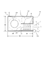
- the schematic structure schematic diagram which shows the internal structure which looked at the ion generator which attached the ion generator in the basic composition of this invention in parallel with respect to the wind from an air blower from the side surface side.
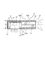
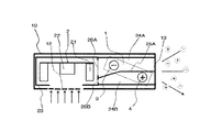
- the schematic structure schematic diagram which shows the internal structure which looked at the ion generator which attached the ion generator in the basic composition of this invention in parallel with respect to the wind from an air blower from the upper part.
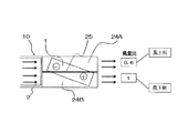
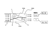
- the figure which shows the air volume ratio of each ventilation path which divided the ventilation path with the internal structure of the ion generator of basic composition.
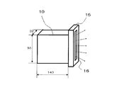
- the perspective view which shows the state which attached the ion-diffusion apparatus to the blower outlet side of the ion generator.
- the schematic structure schematic diagram which shows an example of the structure of the ion diffusion apparatus which attached the ion generator.
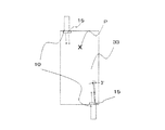
- FIG. 7 is a layout view of an ion generator as viewed from the upper part of a space where the ion concentration measurement of FIG.
- the schematic structure schematic diagram observed from the upper part for demonstrating the structure in 3rd Embodiment of the ion generator of this invention The schematic structure schematic diagram observed from the upper part for demonstrating the structure in 4th Embodiment of the ion generator of this invention.
- FIG. 1 is a schematic diagram of the schematic structure viewed from the side showing the internal structure of the ion generator
- FIG. 2 is a diagram showing the arrangement structure in the blowing direction when the ion generator is viewed from above
- FIG. It is a figure for demonstrating.
- an ion generator 10 is provided with an ion generator 1 that individually generates positive and negative ions in a casing 11 that forms the outline of the ion generator 10.
- a blower 2 for releasing generated ions to the outside of the ion generator 10 is provided beside the ion generator 1 and in the left side in FIG.
- the blower 2 includes, for example, a sirocco fan 21 and includes a motor 22 that rotates the sirocco fan 21.
- the fan constituting the blower 2 is not limited to a sirocco fan, and any fan may be used as long as it aims to blow air.
- the housing 11 has a substantially rectangular parallelepiped shape as an example, and is opposed to the sirocco fan 21 constituting the blower 2, and is formed with a suction port 12 that sucks external air into the housing 11.
- the air sucked from the outside with respect to the suction port 12 is changed in the direction of the ion generator 1 by the rotation of the sirocco fan 21, and the blower outlet 13 that discharges outside the ion generator 10 has the suction port.
- 12 is provided on the surface side in a direction orthogonal to the direction 12.
- An air passage 24 that passes through the positive ion generator 4 and the negative ion generator 3 of the ion generator 1 is communicated downstream of the blower 2.
- the air passage 24 constitutes a part of the air passage that communicates the suction port 12 and the air outlet 13, and the blower 2 is disposed on the upstream side of the air passage.
- the blower 2 has a blower guide 23 so as to surround an outer peripheral surface with a predetermined interval from the sirocco fan 21.
- the air blowing guide 23 is provided so as to communicate with the inlet 26 of the air passage 24 so that the sucked air can be efficiently discharged from the outlet 13 through the ion generator 1.
- the ion generator 1 is provided with a negative ion generator 3 and a positive ion generator 4 so as to generate positive and negative ions individually.
- the negative ion generator 3 and the positive ion generator 4 are provided with the ion generator 1 with the discharge port facing the air passage 24.
- the negative ion generator 3 and the positive ion generator 4 of the ion generator 1 are arranged so that the arrangement state is inclined with respect to the air passage 24 as shown in FIG. That is, the positive ion generator 4 and the negative ion generator 3 are arranged so that the linear direction connecting the centers of the negative ion generator 3 and the positive ion generator 4 is inclined with respect to the ventilation direction of the air passage 24. .
- the negative ion generation part 3 is arrange
- the air passage 24 is provided with a partition member 25 for dividing the air passage 24 by dividing the air passage 26 from the inlet 26 to the outlet 13 in two.
- the negative ion generator 3 is positioned in one first air path 24A of the air path 24 divided into two by the partition member 25, and the positive ion generator 4 is positioned in the other second air path 24B. Yes.
- the negative ions generated in the negative ion generator 3 located on the windward side by the air blown by the blower 2 pass through the first ventilation 24A and are combined with the positive ions generated in the positive ion generator 4 on the leeward side. It is discharged from the air outlet 13 in a state where it is prevented from being summed.
- the positive ions generated in the leeward positive ion generator 4 are discharged from the outlet 13 without being combined with the negative ions in the air passage 24.
- the positive and negative ions generated individually by the ion generator 1 are efficiently discharged from the outlet 13.
- the negative ion generation part 3 and the positive ion generation part 4 of the ion generator 1 are arranged in a state of being spaced apart in the air blowing direction along the air blowing direction of the air passage 24,
- the ion generator 10 as narrow as possible can be provided without increasing the dimension (width) in the direction orthogonal to the blowing direction.
- the positive and negative ions are released from the outlet 13 in such a manner that the positive and negative ions are prevented from being combined with each other in the air passage 24 by the partition member 25.
- the ion generator 10 can be efficiently sent out.
- the ion generator 10 can be installed even in a narrow limited space, and the arrangement position and the like can be reduced, and the generated ions can be sterilized, sterilized, and odors can be removed.
- the ion generator having the basic configuration described above was used for verification to further increase the generation efficiency of positive and negative ions.
- a partition member 25 is provided so as to separate the positive ion generation unit 4 and the negative ion generation unit 3, and the generated ions disappear by bonding or the like. This is also for obtaining an ion generator capable of suppressing positive ions as much as possible, efficiently releasing positive and negative ions, and improving the ion balance at that time.
- the ion generator 10 of the basic configuration is provided with a partition member 25 so as to separate the positive ion generation unit 4 and the negative ion generation unit 3 in order to eliminate the influence of leeward ions on the windward side. is doing.
- the vent path 24 through which the air is blown in the ion generator 1 arranged is divided into two equal parts by the partition member 25 (the cross-sectional area is the same).
- the ion generator 1 is arrange
- the positive ion generator 4 and the negative ion generator 3 are arranged so that a straight line connecting the centers is inclined so as to correspond to the air passages 24A and 24B divided by the partition member 25.
- the outer dimensions that is, the dimensions of the main body of the ion generator 10 on which the ion generator 1 is mounted are shown below.
- the direction of the blown wind direction is front and rear
- the outlet 13 side is the front
- the back of the opposite side is the rear.
- the length (depth) in the front-rear direction is 140 mm as shown in FIG. 1.
- the ion generator 1 side is the upper part
- the ventilation path 24 side is the lower part
- the vertical height is 93 mm.
- the width of the left-right direction seen from the blower outlet 13 side of the machine 10 is set to 32 mm.
- the sirocco fan 21 was provided and the maximum air volume was 0.39 m ⁇ 3 > / min.
- the negative ion generation part 3 is arrange
- the positive ion generation part 4 is arrange
- a partition member 25 is provided between the two ion generators 3 and 4, and the air passage 24 passing through the two ion generators 3 and 4 is divided into a first air passage 24A and a second air passage 24B. As described above, the air passage 24 is divided into two equal parts.
- the ion generator 15 as shown in FIG. 4 is attached to the ion generator 10 so as to correspond to the air outlet 13.
- the air outlet 16 of the ion diffusing device 15 is also formed in the upper part of the air outlet 13 of the main body of the ion generator 10, particularly in a portion where the air outlet 13 corresponding to the ion generator 1 does not exist.
- the shape of the air outlet 16 of the ion diffusing device 15 is narrower than the width of the air outlet 13 so that air is also blown out from the portion facing the ion generator 1, and the ion generator 1 side. Also extended to form.
- the deflecting plate (deflecting member) 17 is the edge of the partition member 25 so that the wind direction is about 3 ° inward with respect to the front blowing direction of the ion diffusing device 15 as shown in FIG. It is provided with a slanting appearance that extends from.
- the space is a space as shown in FIG.
- the ion generator 10 is arranged in a space 30 shown in FIG.
- the space 30 is surrounded by front and rear walls 31 and 32 to which the ion generator 10 is mounted, left and right side walls 33 and 34 with respect to the ion generator 10, a vertical ceiling wall 35, and a bottom wall (bottom surface) 36. .
- the two ion generators 10 are attached to the front and rear walls 31 and 32 constituting the space 30 so that the respective outlets 13 face each other.
- the space 30 has a space (depth) of 2000 mm (2 m) in the front-rear direction and a top wall 35 and a bottom wall 36 in the vertical direction.
- the ion generators 10 provided on the front and rear surfaces of the space 30 face each other so that the center of the outlet 16 of the ion diffusion device 15 is located at a position of 100 mm from the left and right side walls and a height of 1165 mm from the bottom surface in FIG. Installed. As shown in FIG. 7, in each ion generator 10, the above-described ion diffusion device 15 that is blown to the inner surface of about 3 ° is attached to the surfaces of the left and right side walls 33 and 34.
- the ion generator 10 arranged as described above was operated, and the ion concentration was measured using an ion counter in order to confirm the amount of ions released.
- the installation position of the ion counter that is, the measurement point P is 1200 mm from the bottom plate (bottom wall) 36, the center of the left and right side walls, that is, 500 mm from the side walls 33 and 34, and 500 mm from the rear wall to which the ion generator 10 is attached.
- An ion counter was installed so that
- Table 1 below shows the results of measuring the ion concentration in the state shown in FIGS.
- the positive ion concentration was higher than the negative ion concentration. This is because positive ions generated on the leeward side where the air volume is large affect negative ions generated on the windward side, positive ions: 32,600 / cm 3 , negative ions: 11,000 / cm 3 , The positive ions on the leeward side are about three times as large as the negative ions. Thus, even if the two ion generators 3 and 4 are simply divided equally by the partition member 25, the released ion balance is It has not improved so much.
- the ion generator 10 As described above, in the ion generator 10 according to the basic configuration, even if the ions generated from the positive ion generator 4 and the negative ion generator 3 are separated by the partition member 25 so as not to interfere with each other, the ion balance is not improved. .
- the concentration of negative ions is also relatively high, and there is an effect obtained by providing the partition member 25 and partitioning the air passages of the respective ion generators.
- FIG. 8 is a diagram showing the ion generator 10 according to the first embodiment, showing an internal structure, and particularly corresponding to the ion generator 10 of FIG. 2 for explaining the basic configuration.
- the ion generator will be described with the same reference numeral 10.
- symbol is changed about a different part from a basic structure, and the detail is demonstrated. That is, the same reference numerals are the same as those described in the basic configuration.
- the partition member 25 is different in the ion generator 10 according to the first embodiment.
- the partition member in the first embodiment is denoted by reference numeral 25A as shown in FIG.
- the partition member 25 ⁇ / b> A in the first embodiment is formed in a dogleg shape so that the windward part from the middle of the partition for dividing the air passage 24 into two is directed toward the suction port 12. ing. That is, the cross-sectional area of the inlet 26A on the first ventilation path 24A side where the ventilation path 24 is divided is made larger than the inlet 26B of the second ventilation path 24B. In order to improve the balance between positive ions and negative ions, the cross-sectional area of the inlet 26A of the first air passage 24A is increased compared to the second air passage 24B, so that the negative ion generator 3 on the windward side This is to increase the air volume ratio of the first ventilation path 24A installed. That is, the partition member 25A divides the air passage 24, and the amount of air passing through one of the divided first air passages 24A is different from the amount of air passing through the other second air passage 24B. The air volume on the air passage 24A side is increased.
- the ion diffusion device 15 is attached to the ion generator 10 using the partition member 25A so as to face the air outlet 13, and in the space 30 shown in FIG. 6 and FIG.
- the ion concentration was measured.
- the measurement results are as shown in Table 2.
- positive ions were about 1.5 times negative ions.
- the air volume ratio is 2.5 times, the amount of ions on the windward side is smaller than the amount of ions on the leeward side.
- the ion balance is improved and improved.
- the ventilation path 24 for the positive ion generation section 4 and the negative ion generation section 3 is divided into the first and second ventilation paths 24A and 24B using the partition member 25A, the second on the inlet 12 side.
- the air volume to the ventilation path 24B was configured to be smaller than the other. As a result, the ion balance was improved and greatly improved. As a result, the effect of positive and negative ions can be enhanced.
- the air volume of the first air passage 24A of the negative ion generator 3 arranged on the windward side is made larger than that of the second air passage 24B of the positive ion generator 4 arranged on the leeward side.
- the air passage 24 is partitioned by the partition member 25. That is, in order to increase the air volume, the partition member 25 is formed in a shape that changes the cross-sectional area of the inlet 26 of the air passage 24.
- FIG. 10 is a diagram illustrating a configuration of the ion generator 10 according to the second embodiment of the present invention.
- the difference between the ion generator 10 of the second embodiment and the ion generator 10 according to the first embodiment described above is that the ion generator 1 is different from the negative ion generator 3 and the positive ion generator 4 in the ion generator 1.
- the arrangement position is changed.
- the ion concentration in the space shown in FIGS. 6 and 7 was measured in the same manner as the ion generator in the first embodiment.
- the air volume ratio between the first air passage 24A and the second air passage 24B is the air volume ratio shown in FIG. 9 as in the ion generator 10 according to the first embodiment. Is equivalent to
- the ion diffusing device 15 was attached, and the ion concentration was measured in the space 30 shown in FIGS. The results are as shown in Table 3.
- positive ions were 30,700 / cm 3 and negative ions were 32,600 / cm 3 , so that the ion balance was the best.
- the negative ion concentration is higher than the positive ion concentration but also the negative ion increase rate is about 18% while the negative ion increase rate is about 18%.
- the decrease in positive ion concentration was small with respect to the increase in negative ion concentration. This is because positive ions are harder to disappear than negative ions, as can be seen from the fact that there are naturally more positive ions than negative ions in nature.
- the positive ion generator 4 is installed on the windward side, and the negative ion generator 3 is installed on the leeward side, so that the ion generator 1 is used substantially in parallel with the wind direction.
- the generator 10 can also create a space in which ions are balanced.
- the ion generator 10 having the air curtain function is not limited to the ion generator 10 shown in the second embodiment and the first embodiment, but includes the ion generator 1 and the room.
- the present invention can be used for an air purifier that purifies air and sends it out indoors, and an air purifying method including the same. The same applies to the embodiments described below.
- FIG. 11 is a diagram showing a configuration of an ion generator 10 according to the third embodiment of the present invention.
- the difference between the ion generator 10 according to the third embodiment and the ion generator 10 according to the first embodiment described above is the same as that according to the basic configuration of the partition member 25 that divides the air passage 24.
- the difference is that a resistor 27 for limiting the air volume on the second air passage 24B side is provided so as to correspond to the inflow port 26B so that the ratio becomes 5: 1.
- the air amount ratio with the first air passage 24A is 2.5: 1 as described above. did.
- the ion concentration in the space shown in FIGS. 6 and 7 was measured in the same manner as the ion generator in the first embodiment.
- the air flow ratio between the first air passage 24A and the second air passage 24B is the same as described above, as in the ion generator 10 according to the first embodiment. .
- the ion diffusing device 15 was attached, and the ion concentration was measured in the space 30 shown in FIGS. The results are as shown in Table 4.
- the configuration of the ion generator 10 is the same as that of the basic configuration of the present invention, and the ion generator 1 is provided with the resistor 27 in the same manner as in the first embodiment, thereby providing an air flow ratio.
- the ratio of the first air passage 24A and the second air passage 24B was 2.5: 1.
- the same result as in the first embodiment could be obtained.
- the partition member 25 can be linear, which is advantageous in terms of manufacturing.
- a mesh As the structure of the resistor 27, a mesh, a lattice, a perforated plate, or the like can be used.
- FIG. 12 is a diagram showing a configuration of an ion generator 10 according to the fourth embodiment of the present invention.
- a straight line connecting the center of the negative ion generator 3 of the ion generator 1 and the center of the generator of the positive ion generator 4 as shown in FIG. It is arranged in accordance with the air flow direction of 24 winds. Therefore, as the partition member 25B for dividing the air passage 24, the cross-sectional area of the inlet 26A of the first air passage 24A is larger than the cross-sectional area of the inlet 26B of the second air passage 24B close to the suction port 12 side.
- the ratio is 1: 3, and the cross-sectional area of the inlet 26A is three times that of the inlet 26B.
- the air outlet 13 side of the first air passage 24A and the second air passage 24B is opposite to the inflow side.
- the ventilation path 24 is divided so that the center part side of the partition member 25B may be inclined, that is, inclined. About this inclined part, it is good also as a curved shape.
- the negative ion generator 3 and the positive ion generator 4 of the ion generator 1 are arranged linearly in parallel with the ventilation direction.
- the air volume ratio between the first ventilation path 24A and the second ventilation path 24B can be made substantially the same as in the first to third embodiments.
- the positive ion generator 4 is disposed on the leeward side of the first air passage 24A
- the negative ion generator 3 is disposed on the leeward side of the second air passage 24B. The same effect can be expected.
- the negative ion generator 3 is disposed on the leeward side of the first air passage 24A, and the positive ion generator 4 is disposed on the leeward side of the second air passage 24B, whereby the first embodiment, The same effect as that of the second embodiment can be expected.
- the positive ion generator 4 and the negative ion generator 3 of the ion generator 1 can be arranged linearly in the ventilation direction, the ion generator 1 is arranged obliquely, for example. Therefore, the dimension in the width direction can be further reduced.
- the configuration of the ion generator 10 of each embodiment has been described above, but matters and configurations common to each embodiment are the air flow path 24 for the positive ion generation unit 4 and the negative ion generation unit 3 of the ion generator 1. Are spaced apart from the leeward side and the leeward side so as to be lined up along the blowing direction. At this time, the ventilation path of the air flow path of the positive ion generation part 4 and the negative ion generation part 3 is divided by providing a partition member 25, and each ion generation part is individually arranged so as to correspond to each divided ventilation path. is doing.
- each air passage divided by the partition member 25 the air flow is not the same, but different air flows.
- the other ion generation part is set to be larger than the air volume of the other air passage on the leeward side.
- the cross-sectional area on the inflow side flowing into one air passage is made larger than the cross-sectional area on the inflow side of the other air passage.
- the partition member 25 is formed in a shape that adjusts its cross-sectional area. In order to reduce the air volume, a resistor or the like for limiting the air volume can be provided on the inflow side on the air passage side.
- the air flow rate of the ventilation path corresponding to the ion generation unit disposed opposite to the windward side in the blowing direction is different from that of the other ion generation unit corresponding to the other ion generation unit disposed opposite to the leeward side.
- the side where the air volume is increased is about 2.5 times the side where the air volume is small. Thereby, ion balance can be made favorable.
- the positive ion generating part is arranged on the windward side of the air passage. Therefore, ion balance can further be improved.
- the ion generator 10 described in the above embodiments and basic configurations is described with the first air flow path 24A as the windward side, the positive ion generation unit 4 and the negative ion generation unit 3 being arranged to face each other, and the air volume as the leeward side. It has been described that the air volume is larger than the air flow rate of the second ventilation path 24B, for example, about 2.5 times. Therefore, when the second air passage 24B side is on the windward side and the positive ion generation unit 4 and the negative ion generation unit 3 are arranged to face each other, the air volume of the second air passage 24B is larger than that of the first air passage 24A. For example, it may be set to about 2.5 times. That is, it is only necessary to set the air flow rate on the air flow path side where the ion generating part is provided on the air flow side of the air flow path 24 so as to have the above-described forms.
- the air passage side in which the ion generation unit of the ion generator 1 is disposed on the windward side is made larger than the air volume on the other air passage side, and for example, the shape for dividing the air passage by the partition member 25 may be devised so as to be about 2.5 times.
- a resistor 27 may be provided on one side of the inlet 26 of the air passage 24.
- the ratio of the air volume flowing through the air passage is important.
- the cross section of the air passage is the same, it is clear that the explanation of the air volume ratio is the same as the air speed ratio. Therefore, it is possible to realize the configuration in the above-described embodiment by the wind speed ratio.
- the ion generator 10 of the present invention it is possible to narrow the width direction, that is, the width (dimension) in the left-right direction when the air outlet 13 is viewed from the front, and the generated ions. Can be efficiently discharged outside the machine. The ion balance at this time can be improved. For this reason, there is less restriction on the space in which the ion generator 10 is placed, and the ion generator 10 can be installed even in a narrow space.
- the installation space is limited, but it is possible to install in such a narrow space.
- the ion generator 10 of the present invention can be installed in a narrow space between each game table in a place where a person sits in front of the game table and enjoys the game table.
- a large number of gaming tables are arranged adjacent to each other behind a person sitting on a gaming table such as a pachinko machine or a slot machine.
- the ceiling wall 35 does not exist, but an atmosphere having a relatively high positive / negative ion concentration can be created by the generated ions in the partitioned space region.
Landscapes
- Engineering & Computer Science (AREA)
- Chemical & Material Sciences (AREA)
- Combustion & Propulsion (AREA)
- Mechanical Engineering (AREA)
- General Engineering & Computer Science (AREA)
- Disinfection, Sterilisation Or Deodorisation Of Air (AREA)
Abstract
Description
図1から図3は本発明の基本構成におけるイオン発生機の構成を説明するためのものである。図1はイオン発生機の内部構造を示す側面から目視した概略構造の模式図、図2はイオン発生機を上部より目視した送風方向の配置構造を示す図、また図3は送風量の違いを説明するための図である。
基本構成のイオン発生機10は、先に説明したとおり風上側に対する風下側イオンの影響を無くすために、正イオン発生部4と負イオン発生部3を区分するように間に仕切部材25を設置している。その区分としては配置されたイオン発生装置1を空気が送風される通気路24を仕切部材25にて2等分(断面積でも同等)している。また、イオン発生装置1は、送風機2からの風向きに対して、正イオン発生部4及び負のイオン発生部3の並びが平行になるように配置している。また、正イオン発生部4及び負のイオン発生部3は、仕切部材25にて区分された各通気路24A、24Bに対応させるために、中心を結ぶ直線が傾斜するように配置されている。

図8は、第1の実施形態によるイオン発生機10を示す図であり、内部構造を示すもので、特に基本構成を説明した図2のイオン発生機10に対応するものである。なお、説明の都合上、イオン発生機については、同一符号10を示して説明することにする。以下に説明するイオン発生機10については、基本構成と異なる部分について符号を異ならせ、その詳細について説明することにする。つまり、同一符号については、基本構成において説明した構成と同様である。
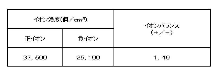
図10は、本発明の第2の実施形態におけるイオン発生機10の構成を示す図である。この第2の実施形態のイオン発生機10と、先に説明した第1の実施形態によるイオン発生機10との違いは、イオン発生装置1において、負イオン発生部3と正イオン発生部4の配置位置を入れ替えたものである。
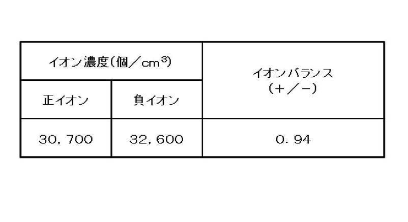
図11は、本発明の第3の実施形態によるイオン発生機10の構成を示す図である。この第3の実施形態のイオン発生機10と、上述した第1の実施形態によるイオン発生機10との違いは、通気路24を区分した仕切部材25を基本構成によるものと同様にした。また、基本構成によるイオン発生機10の違いとしては、第1の通気路24Aと第2の通気路24Bを通る風量を先に説明したように第1通気路24A:第2通気路24B=2.5:1の比率になるように第2通気路24B側の風量を制限するための抵抗体27を、流入口26Bに対応させて設けた点で異なる。このように抵抗体27を設けることで、仕切部材25Aのように、流入口26B側の断面積を小さくした場合と同等の効果を奏することになる。
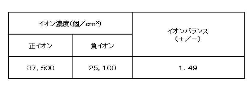
図12は、本発明の第4の実施形態によるイオン発生機10の構成を示す図である。この第4の実施形態のイオン発生機10は、図12に示すようにイオン発生装置1の負イオン発生部3の中心と正イオン発生部4の発生部の中心とを結ぶ直線を、通気路24の風の通気方向と一致させて配置している。そこで、通気路24を区分するための仕切部材25Bとしては、吸込口12側に近い第2通気路24Bの流入口26Bの断面積に対し、第1通気路24Aの流入口26Aの断面積の比率を1:3にし、流入口26Aの断面積を流入口26Bに対し3倍にしている。
2 送風機
3 負イオン発生部
4 正イオン発生部
10 イオン発生機
11 筐体
12 吸込口
13 吹出口
21 シロッコファン
22 モータ
24 通気路
24A 第1通気路
24B 第2通気路
25 仕切部材
25A 仕切部材
25B 仕切部材
26 流入口
26A 流入口(区分された流入口)
26B 流入口(区分された流入口)
Claims (6)
- 空気を吸い込む吸込口と、空気を吹き出す吹出口と、前記吸込口から吸込んだ空気を前記吹出口から送出する送風機と、前記送風機の吐出口と前記吹出口とを連結する通気路と、正イオンを発生する正イオン発生部と負イオンを発生する負イオン発生部とを別々に設けたイオン発生装置とを備え、前記正イオン発生部及び前記負イオン発生部を前記通気路に臨ませて設置して、前記正イオン及び負イオンを前記吹出口から送出するように構成したイオン発生機において、
前記通気路を区分する仕切部材を設け、
区分された一方の通気路の風上側に前記正イオン発生部及び前記負イオン発生部の一方を、区分された他方の通気路の風下側に前記正イオン発生部及び前記負イオン発生部の他方をそれぞれ互いに対向するように配置し、
前記正イオン発生部及び前記負イオン発生部の一方を通過する前記一方の通気路の風量が、前記正イオン発生部及び前記負イオン発生部の他方を通過する前記他方の通気路の風量と異なるようにしたことを特徴とするイオン発生機。 - 前記仕切部材は、前記正イオン発生部及び前記負イオン発生部の一方を通過する前記一方の通気路の風量が、前記正イオン発生部及び前記負イオン発生部の他方を通過する前記他方の通気路の風量よりも多くなるように、前記通気路を区分してなる請求項1に記載のイオン発生機。
- 前記一方の通気路の風量が、前記他方の通気路の風量と異なるように、前記仕切部材にて前記一方の通気路の流入口側の断面積を前記他方の通気路の流入口側の断面積よりも大きくした請求項1又は請求項2に記載のイオン発生機。
- 前記一方の通気路の風量が、前記他方の通気路の風量と異なるように、前記仕切部材に区分された前記他方の通気路の流入口側に風量を制限する抵抗体を設けたことを特徴とする請求項1又は請求項2に記載のイオン発生機。
- 前記イオン発生装置の前記正イオン発生部を風上側、前記負イオン発生部を風下側に設置することを特徴とする請求項1又は請求項2に記載のイオン発生機。
- 前記一方の通気路の風量が、前記他方の通気路の風量の2.5倍程度になるようにしたことを特徴とする請求項1又は請求項2に記載のイオン発生機。
Priority Applications (2)
| Application Number | Priority Date | Filing Date | Title |
|---|---|---|---|
| US13/812,955 US9071040B2 (en) | 2010-07-30 | 2011-06-10 | Ion generator |
| CN201180037268.7A CN103038961B (zh) | 2010-07-30 | 2011-06-10 | 离子发生器 |
Applications Claiming Priority (2)
| Application Number | Priority Date | Filing Date | Title |
|---|---|---|---|
| JP2010-171281 | 2010-07-30 | ||
| JP2010171281A JP4890636B2 (ja) | 2010-07-30 | 2010-07-30 | イオン発生機 |
Publications (1)
| Publication Number | Publication Date |
|---|---|
| WO2012014577A1 true WO2012014577A1 (ja) | 2012-02-02 |
Family
ID=45529797
Family Applications (1)
| Application Number | Title | Priority Date | Filing Date |
|---|---|---|---|
| PCT/JP2011/063316 Ceased WO2012014577A1 (ja) | 2010-07-30 | 2011-06-10 | イオン発生機 |
Country Status (4)
| Country | Link |
|---|---|
| US (1) | US9071040B2 (ja) |
| JP (1) | JP4890636B2 (ja) |
| CN (1) | CN103038961B (ja) |
| WO (1) | WO2012014577A1 (ja) |
Cited By (2)
| Publication number | Priority date | Publication date | Assignee | Title |
|---|---|---|---|---|
| WO2014038168A1 (ja) * | 2012-09-10 | 2014-03-13 | パナソニック株式会社 | 機能性物質、生体活性用薬剤及び機能性物質の生体内への浸透方法、並びに機能性物質放散装置及び空気清浄装置 |
| JP2015146992A (ja) * | 2014-02-07 | 2015-08-20 | シャープ株式会社 | 除菌ケース |
Families Citing this family (12)
| Publication number | Priority date | Publication date | Assignee | Title |
|---|---|---|---|---|
| US8618501B2 (en) * | 2009-05-29 | 2013-12-31 | Sharp Kabushiki Kaisha | Ion generating device for duct |
| JP4890636B2 (ja) | 2010-07-30 | 2012-03-07 | シャープ株式会社 | イオン発生機 |
| JP5111648B1 (ja) * | 2011-08-31 | 2013-01-09 | シャープ株式会社 | イオン発生機 |
| JP5869914B2 (ja) * | 2012-02-28 | 2016-02-24 | シャープ株式会社 | 除電装置 |
| JP5988797B2 (ja) * | 2012-09-18 | 2016-09-07 | シャープ株式会社 | 送風装置用のスタンド |
| KR20150014820A (ko) * | 2013-07-30 | 2015-02-09 | 서울바이오시스 주식회사 | 공기 정화 모듈을 구비하는 공조 장치 |
| CN107917474A (zh) * | 2017-11-15 | 2018-04-17 | 北京众清科技有限公司 | 一种净化器以及室内空气净化系统 |
| JP7378226B2 (ja) * | 2019-05-21 | 2023-11-13 | シャープ株式会社 | 送風機 |
| EP4494625A3 (en) | 2019-07-19 | 2025-03-19 | Aquapass Ltd | Fluid stimulation devices for treating fluid overload |
| IL269021B2 (en) | 2019-08-29 | 2023-05-01 | Riskin Yefim | Air disinfection method and disinfection device |
| CN113566300A (zh) * | 2020-04-29 | 2021-10-29 | 广东美的制冷设备有限公司 | 空调室内机、空调器及控制方法 |
| US20220313863A1 (en) * | 2021-04-06 | 2022-10-06 | John Chris Karamanos | Devices and systems for concentrated biogenic ionization |
Citations (5)
| Publication number | Priority date | Publication date | Assignee | Title |
|---|---|---|---|---|
| JPH09213493A (ja) * | 1996-02-01 | 1997-08-15 | Yokogawa Denshi Kiki Kk | 除電器のイオンバランス調整回路 |
| JP2001035686A (ja) * | 1999-07-15 | 2001-02-09 | Kasuga Electric Works Ltd | 直流除電器 |
| JP2003161494A (ja) * | 2001-11-20 | 2003-06-06 | Sharp Corp | 空気調和システム |
| JP2010080431A (ja) * | 2008-09-26 | 2010-04-08 | Jentorei:Kk | イオン発生方法、イオン発生電極及びイオン発生モジュール |
| JP2010118351A (ja) * | 2010-01-07 | 2010-05-27 | Sharp Corp | イオン発生カートリッジ |
Family Cites Families (19)
| Publication number | Priority date | Publication date | Assignee | Title |
|---|---|---|---|---|
| US4333123A (en) | 1980-03-31 | 1982-06-01 | Consan Pacific Incorporated | Antistatic equipment employing positive and negative ion sources |
| US6221160B1 (en) | 1999-02-03 | 2001-04-24 | Taiwan Semiconductor Manufacturing Co., Ltd | Method and apparatus for environmental control in a process chamber |
| JP3460021B2 (ja) | 2001-04-20 | 2003-10-27 | シャープ株式会社 | イオン発生装置及びこれを搭載した空調機器 |
| JP3438054B2 (ja) | 2001-08-07 | 2003-08-18 | シャープ株式会社 | イオン発生素子 |
| KR100720356B1 (ko) * | 2004-07-27 | 2007-05-22 | 삼성전자주식회사 | 이온 발생기 |
| JP2006280787A (ja) | 2005-04-04 | 2006-10-19 | Shimizu Corp | 空気イオン搬送装置 |
| EP1788327A2 (en) | 2005-11-17 | 2007-05-23 | Samsung Electronics Co.,Ltd. | Refrigerator having independent sterilization duct |
| JP5127347B2 (ja) | 2007-07-31 | 2013-01-23 | パナソニック株式会社 | 空気調和機 |
| JP4573900B2 (ja) * | 2008-08-26 | 2010-11-04 | シャープ株式会社 | 室内の清浄化方法 |
| JP4368409B1 (ja) * | 2008-08-26 | 2009-11-18 | シャープ株式会社 | イオン拡散装置 |
| SG178800A1 (en) | 2008-08-28 | 2012-03-29 | Sharp Kk | Ion detecting apparatus and ion generating apparatus |
| JP4436877B2 (ja) | 2008-08-28 | 2010-03-24 | シャープ株式会社 | イオン発生装置 |
| JP4404948B1 (ja) | 2008-08-28 | 2010-01-27 | シャープ株式会社 | イオン発生装置 |
| JP4628477B2 (ja) | 2009-06-19 | 2011-02-09 | シャープ株式会社 | イオン発生方法と、イオン発生装置およびそれを用いた電気機器 |
| JP2011033293A (ja) | 2009-08-04 | 2011-02-17 | Panasonic Corp | 空気調和機 |
| JP5273733B2 (ja) | 2009-09-14 | 2013-08-28 | シャープ株式会社 | イオン発生装置およびそれを用いた電気機器 |
| JP5530790B2 (ja) | 2010-04-15 | 2014-06-25 | 本田技研工業株式会社 | 内燃機関の吸入空気量制御装置 |
| US9095637B2 (en) | 2010-06-15 | 2015-08-04 | Sharp Kabushiki Kaisha | Ion generator and air cleaner |
| JP4890636B2 (ja) | 2010-07-30 | 2012-03-07 | シャープ株式会社 | イオン発生機 |
-
2010
- 2010-07-30 JP JP2010171281A patent/JP4890636B2/ja active Active
-
2011
- 2011-06-10 CN CN201180037268.7A patent/CN103038961B/zh not_active Expired - Fee Related
- 2011-06-10 WO PCT/JP2011/063316 patent/WO2012014577A1/ja not_active Ceased
- 2011-06-10 US US13/812,955 patent/US9071040B2/en not_active Expired - Fee Related
Patent Citations (5)
| Publication number | Priority date | Publication date | Assignee | Title |
|---|---|---|---|---|
| JPH09213493A (ja) * | 1996-02-01 | 1997-08-15 | Yokogawa Denshi Kiki Kk | 除電器のイオンバランス調整回路 |
| JP2001035686A (ja) * | 1999-07-15 | 2001-02-09 | Kasuga Electric Works Ltd | 直流除電器 |
| JP2003161494A (ja) * | 2001-11-20 | 2003-06-06 | Sharp Corp | 空気調和システム |
| JP2010080431A (ja) * | 2008-09-26 | 2010-04-08 | Jentorei:Kk | イオン発生方法、イオン発生電極及びイオン発生モジュール |
| JP2010118351A (ja) * | 2010-01-07 | 2010-05-27 | Sharp Corp | イオン発生カートリッジ |
Cited By (3)
| Publication number | Priority date | Publication date | Assignee | Title |
|---|---|---|---|---|
| WO2014038168A1 (ja) * | 2012-09-10 | 2014-03-13 | パナソニック株式会社 | 機能性物質、生体活性用薬剤及び機能性物質の生体内への浸透方法、並びに機能性物質放散装置及び空気清浄装置 |
| JP2014051478A (ja) * | 2012-09-10 | 2014-03-20 | Panasonic Corp | 機能性物質、生体活性用薬剤及び機能性物質の生体内への浸透方法、並びに機能性物質放散装置及び空気清浄装置 |
| JP2015146992A (ja) * | 2014-02-07 | 2015-08-20 | シャープ株式会社 | 除菌ケース |
Also Published As
| Publication number | Publication date |
|---|---|
| US9071040B2 (en) | 2015-06-30 |
| CN103038961A (zh) | 2013-04-10 |
| JP4890636B2 (ja) | 2012-03-07 |
| CN103038961B (zh) | 2014-12-10 |
| JP2012033360A (ja) | 2012-02-16 |
| US20130126749A1 (en) | 2013-05-23 |
Similar Documents
| Publication | Publication Date | Title |
|---|---|---|
| JP4890636B2 (ja) | イオン発生機 | |
| KR101268175B1 (ko) | 이온 발생 장치 | |
| US9061084B2 (en) | Fine particle diffusion device | |
| JP4813614B1 (ja) | 車両 | |
| CN201516186U (zh) | 微粒扩散装置 | |
| JP4866468B2 (ja) | 送風ファン及びそれを用いたサーキュレータ、微小粒子拡散装置 | |
| JP5337229B2 (ja) | 遊技台間イオン発生機 | |
| WO2013038765A1 (ja) | 微小粒子拡散装置 | |
| US9682165B2 (en) | Fine particle diffusion device | |
| JP4368409B1 (ja) | イオン拡散装置 | |
| JP5851796B2 (ja) | イオン発生機 | |
| JP5088359B2 (ja) | 放電ユニット及び空気調和機 | |
| JP2023010135A (ja) | 飛沫吸入排出装置 | |
| JP5113247B2 (ja) | 遊技施設用汚染空気浄化システム | |
| JP5015272B2 (ja) | サーキュレータ及び微小粒子拡散装置 | |
| JP5088360B2 (ja) | 放電ユニット及び空気調和機 | |
| JP2013191476A (ja) | イオン発生装置及びイオン発生方法 | |
| JP2011072707A (ja) | 空気清浄装置 | |
| JP2016034563A (ja) | 送風装置および送風ユニット | |
| JP2011258469A (ja) | イオン発生装置、空気清浄機、イオン発生方法 |
Legal Events
| Date | Code | Title | Description |
|---|---|---|---|
| WWE | Wipo information: entry into national phase |
Ref document number: 201180037268.7 Country of ref document: CN |
|
| 121 | Ep: the epo has been informed by wipo that ep was designated in this application |
Ref document number: 11812170 Country of ref document: EP Kind code of ref document: A1 |
|
| WWE | Wipo information: entry into national phase |
Ref document number: 13812955 Country of ref document: US |
|
| NENP | Non-entry into the national phase |
Ref country code: DE |
|
| 122 | Ep: pct application non-entry in european phase |
Ref document number: 11812170 Country of ref document: EP Kind code of ref document: A1 |