WO2012014575A1 - リールの組込方法及びマガジン - Google Patents
リールの組込方法及びマガジン Download PDFInfo
- Publication number
- WO2012014575A1 WO2012014575A1 PCT/JP2011/063177 JP2011063177W WO2012014575A1 WO 2012014575 A1 WO2012014575 A1 WO 2012014575A1 JP 2011063177 W JP2011063177 W JP 2011063177W WO 2012014575 A1 WO2012014575 A1 WO 2012014575A1
- Authority
- WO
- WIPO (PCT)
- Prior art keywords
- reel
- drive device
- hub
- upper cartridge
- cartridge
- Prior art date
- Legal status (The legal status is an assumption and is not a legal conclusion. Google has not performed a legal analysis and makes no representation as to the accuracy of the status listed.)
- Ceased
Links
Images













Classifications
-
- G—PHYSICS
- G11—INFORMATION STORAGE
- G11B—INFORMATION STORAGE BASED ON RELATIVE MOVEMENT BETWEEN RECORD CARRIER AND TRANSDUCER
- G11B23/00—Record carriers not specific to the method of recording or reproducing; Accessories, e.g. containers, specially adapted for co-operation with the recording or reproducing apparatus ; Intermediate mediums; Apparatus or processes specially adapted for their manufacture
- G11B23/02—Containers; Storing means both adapted to cooperate with the recording or reproducing means
- G11B23/04—Magazines; Cassettes for webs or filaments
- G11B23/08—Magazines; Cassettes for webs or filaments for housing webs or filaments having two distinct ends
- G11B23/087—Magazines; Cassettes for webs or filaments for housing webs or filaments having two distinct ends using two different reels or cores
-
- G—PHYSICS
- G11—INFORMATION STORAGE
- G11B—INFORMATION STORAGE BASED ON RELATIVE MOVEMENT BETWEEN RECORD CARRIER AND TRANSDUCER
- G11B15/00—Driving, starting or stopping record carriers of filamentary or web form; Driving both such record carriers and heads; Guiding such record carriers or containers therefor; Control thereof; Control of operating function
- G11B15/18—Driving; Starting; Stopping; Arrangements for control or regulation thereof
- G11B15/26—Driving record carriers by members acting directly or indirectly thereon
- G11B15/32—Driving record carriers by members acting directly or indirectly thereon through the reels or cores on to which the record carrier is wound
-
- G—PHYSICS
- G11—INFORMATION STORAGE
- G11B—INFORMATION STORAGE BASED ON RELATIVE MOVEMENT BETWEEN RECORD CARRIER AND TRANSDUCER
- G11B23/00—Record carriers not specific to the method of recording or reproducing; Accessories, e.g. containers, specially adapted for co-operation with the recording or reproducing apparatus ; Intermediate mediums; Apparatus or processes specially adapted for their manufacture
- G11B23/02—Containers; Storing means both adapted to cooperate with the recording or reproducing means
- G11B23/04—Magazines; Cassettes for webs or filaments
- G11B23/041—Details
- G11B23/044—Reels or cores; positioning of the reels in the cassette
-
- G—PHYSICS
- G11—INFORMATION STORAGE
- G11B—INFORMATION STORAGE BASED ON RELATIVE MOVEMENT BETWEEN RECORD CARRIER AND TRANSDUCER
- G11B23/00—Record carriers not specific to the method of recording or reproducing; Accessories, e.g. containers, specially adapted for co-operation with the recording or reproducing apparatus ; Intermediate mediums; Apparatus or processes specially adapted for their manufacture
- G11B23/02—Containers; Storing means both adapted to cooperate with the recording or reproducing means
- G11B23/04—Magazines; Cassettes for webs or filaments
- G11B23/08—Magazines; Cassettes for webs or filaments for housing webs or filaments having two distinct ends
- G11B23/087—Magazines; Cassettes for webs or filaments for housing webs or filaments having two distinct ends using two different reels or cores
- G11B23/08707—Details
- G11B23/08721—Brakes for tapes or tape reels
-
- G—PHYSICS
- G11—INFORMATION STORAGE
- G11B—INFORMATION STORAGE BASED ON RELATIVE MOVEMENT BETWEEN RECORD CARRIER AND TRANSDUCER
- G11B23/00—Record carriers not specific to the method of recording or reproducing; Accessories, e.g. containers, specially adapted for co-operation with the recording or reproducing apparatus ; Intermediate mediums; Apparatus or processes specially adapted for their manufacture
- G11B23/02—Containers; Storing means both adapted to cooperate with the recording or reproducing means
- G11B23/04—Magazines; Cassettes for webs or filaments
- G11B23/08—Magazines; Cassettes for webs or filaments for housing webs or filaments having two distinct ends
- G11B23/087—Magazines; Cassettes for webs or filaments for housing webs or filaments having two distinct ends using two different reels or cores
- G11B23/08707—Details
- G11B23/08728—Reels or cores; positioning of the reels in the cassette
-
- G—PHYSICS
- G11—INFORMATION STORAGE
- G11B—INFORMATION STORAGE BASED ON RELATIVE MOVEMENT BETWEEN RECORD CARRIER AND TRANSDUCER
- G11B23/00—Record carriers not specific to the method of recording or reproducing; Accessories, e.g. containers, specially adapted for co-operation with the recording or reproducing apparatus ; Intermediate mediums; Apparatus or processes specially adapted for their manufacture
- G11B23/02—Containers; Storing means both adapted to cooperate with the recording or reproducing means
- G11B23/113—Apparatus or processes specially adapted for the manufacture of magazines or cassettes, e.g. initial loading into container
-
- Y—GENERAL TAGGING OF NEW TECHNOLOGICAL DEVELOPMENTS; GENERAL TAGGING OF CROSS-SECTIONAL TECHNOLOGIES SPANNING OVER SEVERAL SECTIONS OF THE IPC; TECHNICAL SUBJECTS COVERED BY FORMER USPC CROSS-REFERENCE ART COLLECTIONS [XRACs] AND DIGESTS
- Y10—TECHNICAL SUBJECTS COVERED BY FORMER USPC
- Y10T—TECHNICAL SUBJECTS COVERED BY FORMER US CLASSIFICATION
- Y10T29/00—Metal working
- Y10T29/49—Method of mechanical manufacture
- Y10T29/49815—Disassembling
- Y10T29/49817—Disassembling with other than ancillary treating or assembling
Definitions
- the present invention relates to a method of incorporating a pair of reels into a drive device so that they cannot be taken out, and a magazine in which the reels are stored.
- a recording tape cartridge in which a recording tape such as a magnetic tape used mainly as an information recording / reproducing medium (data backup) for a computer or the like is wound around a reel and the reel is housed in a single case. It is known (for example, see JP 2010-79989 A).
- the recording tape cartridge When this recording tape cartridge is loaded into the drive device, the recording tape is pulled out from the reel and taken up on the take-up reel of the drive device. Information is written to or read from the recording tape by the recording / reproducing head of the drive device.
- an object of the present invention is to provide a method for assembling a reel that can ensure the ease of assembling a pair of reels incorporated in a drive device into the drive device, and a magazine in which the reels are accommodated. To do.
- a reel assembling method includes an upper cartridge and a lower cartridge that is removable from the upper cartridge, each of which includes a reel hub.
- the upper cartridge holding the reel hub of the reel and the second reel is conveyed to the drive device, and the reel hub of the first reel and the second reel are placed on a pair of rotating members of the drive device.
- a fixing step of fixing the reel hubs of the first reel and the second reel to the rotating members of the drive device are examples of fixing the reel hubs of the first reel and the second reel to the rotating members of the drive device.
- the reel assembling method according to the second aspect of the present invention is the reel assembling method according to the above aspect, wherein the engaged portion formed in the upper cartridge at the time of the arranging step The engaging part of the drive device is engaged.
- the first reel and the second reel can be easily positioned and arranged on the pair of rotating members of the drive device.
- the reel assembling method of the third aspect according to the present invention is the reel assembling method of the above aspect, wherein the recording tape is guided by a temporary guide provided in the upper cartridge, At the time of the placement step or the release step, the recording tape guided by the temporary guide is delivered to the main guide of the drive device.
- a reel assembling method wherein the reel is assembled at both ends of the reel hub of the first reel and both ends of the reel hub of the second reel. Are provided with flanges, and when the first reel and the second reel are accommodated in the magazine, at least the flange is not in contact with the inner surface of the magazine.
- the magazine according to the fifth aspect of the present invention is wound around the outer peripheral surface of at least one of the first reel and the second reel and the first and second reel hubs each having a reel hub.
- the reel hub of the first reel is disposed at the first assembly position of the drive device
- the reel hub of the second reel is the second assembly of the drive device.
- a reel holding mechanism that holds the upper cartridge in a non-rotatable state in a positioned state.
- the first reel and the second reel incorporated in the drive device can be incorporated while being positioned and held in the upper cartridge, the incorporation into the drive device can be ensured.
- a magazine according to a sixth aspect of the present invention is the magazine according to the above aspect, wherein the reel holding mechanism is a first rotational position defining member attached so as to rotate integrally with a reel hub of the first reel.
- a second rotational position defining member attached to the reel hub of the second reel so as to rotate integrally; and a lock member for locking the first rotational position defining member and the second rotational position defining member so as not to rotate.
- a magazine according to the above aspect, wherein the locking member has a temporary guide for guiding the recording tape, and the upper cartridge is incorporated in the drive device.
- the lock of the locking member with respect to the first rotational position defining member and the second rotational position defining member is released, and the temporary guide is retracted from the recording tape, whereby the recording tape is moved to the main guide of the drive device. It is configured to be able to deliver.
- a magazine according to the above aspect, wherein the upper cartridge can be opened at a lower portion thereof, and the upper cartridge accommodates the first reel and the second reel. And the lock member is locked to the first rotational position defining member and the second rotational position defining member by holding the temporary guide in a guide holding portion provided in the lower cartridge. Fixed in position.
- the rotation lock for the first reel and the second reel can be easily performed.
- the magazine according to the above aspect wherein the locking member is configured such that the temporary guide is retracted from the recording tape, and the recording tape is received by the main guide of the drive device. It is configured to be removable after being delivered.
- the lock member in the work after the recording tape is transferred from the temporary guide to the main guide of the drive device, the lock member can be kept out of the way.
- a magazine according to the above aspect, wherein the upper cartridge is configured such that a lower portion of the upper cartridge can be opened, and the first cartridge and the second reel are accommodated by the upper cartridge. And a flange is provided at each end of the reel hub of the first reel and at both ends of the reel hub of the second reel, and the reel holding mechanism has the flange connected to the upper cartridge.
- a first vertical position defining member that defines the vertical position of the reel hub of the first reel and a vertical position of the reel hub of the second reel so as not to contact the inner surface and the inner surface of the lower cartridge.
- a second vertical position defining member is provided.
- an eleventh aspect of the magazine according to the present invention is the magazine of the above aspect, wherein the first vertical position defining member and the second vertical position defining member are rotated in one direction, whereby the first A holding state that defines the vertical position of each reel hub of the reel and the second reel is taken, and a holding release state that releases the vertical position of each reel hub by rotating in one direction or the other direction. It is configured to take.
- the vertical positions of the first reel and the second reel can be easily defined.
- the magazine of the twelfth aspect according to the present invention is the magazine of the above aspect, and a magnetic metal is provided on the inner peripheral surface side of each reel hub of the first reel and the second reel,
- the first vertical position defining member and the second vertical position defining member take a holding state that defines the vertical position of each reel hub by attracting the magnetic metal of each reel hub by magnetic force, and each reel hub By releasing the adsorption of the magnetic metal by the magnetic force, the reel hub is configured to take a holding release state in which the vertical position of each reel hub is released.
- the vertical positions of the first reel and the second reel can be easily defined.
- a magazine according to the above aspect, wherein the upper cartridge engages with an engaging portion provided in the drive device, and the drive device includes the first cartridge. There are engaged portions for positioning the first reel and the second reel with respect to the assembly position and the second assembly position, respectively.
- the first reel and the second reel can be easily positioned and arranged at each built-in position of the drive device.
- a magazine according to a fourteenth aspect of the present invention is the magazine according to the above aspect, wherein a rotating member is disposed at each of the first and second assembly positions, and the reel hub and A circumferential direction of the reel hub relative to the rotating member, with a convex portion formed on one of the rotating members and a concave portion formed on the other of the reel hub and the rotating member and fitted to the convex portion A positioning part for defining the position of the is configured.
- the circumferential positions of the reel hubs of the first reel and the second reel can be positioned with respect to the rotating member of the drive device. Therefore, it is possible to easily match the position of the screw hole provided in each reel hub with the position of the screw boss provided in the rotating member.
- a magazine according to the above aspect, wherein the upper cartridge is configured such that a lower portion of the upper cartridge can be opened, and the upper cartridge accommodates the first reel and the second reel.
- the lower cartridge is configured to support the first reel and the second reel by being fixed to the upper cartridge by a fastener provided on the upper cartridge side.
- the first reel and the second reel held by the upper cartridge can be fixed in the magazine.
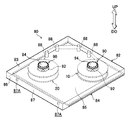
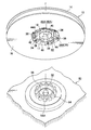
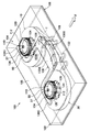
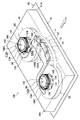
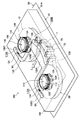
- the perspective view which shows the drive device with which the reel was integrated The perspective view at the time of seeing the magazine concerning a 1st embodiment from the upper part
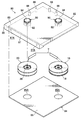
- the perspective view at the time of seeing the magazine concerning a 1st embodiment from the lower part The exploded perspective view of the magazine concerning a 1st embodiment
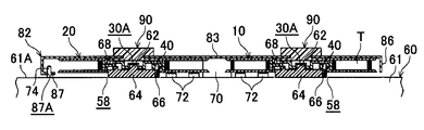
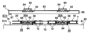
- Explanatory drawing which shows the process of incorporating a reel in a drive device using the magazine which concerns on 1st Embodiment.
- Explanatory drawing which shows the process of incorporating a reel in a drive device using the magazine which concerns on 1st Embodiment.
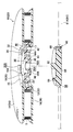
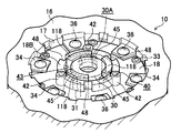
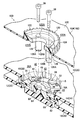
- a perspective sectional view showing a reel and a rotating member of a drive device A perspective sectional view showing a reel fixed to a rotating member of a drive device
- worn The perspective view at the time of seeing the magazine concerning a 2nd embodiment from the upper part
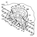
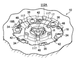
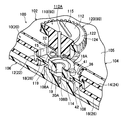
- the perspective sectional view showing the up-and-down position defining member and the rotational position defining member of the magazine according to the second embodiment The exploded perspective view which expands and shows the up-and-down position regulation member and rotation position regulation member of the magazine which concern on 2nd Embodiment.
- the perspective view which shows the attachment structure of the up-and-down position regulation member shown in FIG. The perspective view which shows the attachment structure of the up-and-down position regulation member shown in FIG.
- the perspective view which shows the lower surface of the reinforcement part of the reel fixed to the rotation member of a drive apparatus Sectional view showing the lock hole to lock the tape guide of the lock member and the guide groove to guide Sectional view showing the lock hole to lock the tape guide of the lock member and the guide groove to guide
- the top view which shows the meshing structure of the lock gear of a lock member, and the engagement gear of a rotation position regulation member The top view which shows the meshing structure of the lock gear of a lock member, and the engagement gear of a rotation position regulation member
- Explanatory drawing which shows the process of removing the lower cartridge of the magazine which concerns on 2nd Embodiment, and incorporating it in a drive apparatus.
- Explanatory drawing which shows the process of removing the lower cartridge of the magazine which concerns on 2nd Embodiment, and incorporating it in a drive apparatus.
- Explanatory drawing which shows the process until it incorporates the magazine which concerns on 2nd Embodiment in a drive device, and removes an upper cartridge.
- Explanatory drawing which shows the process until it incorporates the magazine which concerns on 2nd Embodiment in a drive device, and removes an upper cartridge.
- the perspective view which shows the magazine which concerns on 2nd Embodiment of the state which removed the lower cartridge and integrated in the drive device The perspective view which shows the magazine which concerns on 2nd Embodiment of the state which cancelled
- FIG. 1 The perspective view which shows the attachment structure of the up-and-down position regulation member shown in FIG.
- FIG. 2 The perspective view which shows the attachment structure of the up-and-down position regulation member shown in FIG.
- the arrow UP in FIGS. 1 and 2 is the upward direction
- the arrow DO is the downward direction
- the rotation axis directions of the reel 10 as the first reel and the reel 20 as the second reel according to this embodiment are shown.
- the reels 10 and 20 according to the present embodiment are made of synthetic resin such as polycarbonate (PC), for example.
- PC polycarbonate
- the housing 61 of the drive device 60 in FIG. 1, the bottom plate 61A and three Only one column 61B is shown).
- the reel 10 is used for feeding a recording tape T described later, and the reel 20 is used for winding a recording tape T described later.
- the recording tape T fed from the reel 10 is wound around the reel 20. While being taken, it comes into sliding contact with the recording / reproducing head 70. That is, the recording / reproducing head 70 records data on the recording tape T and reproduces data recorded on the recording tape T.
- a plurality of tape guides (main guides) 72 are provided on the bottom plate 61A on both sides of the recording / reproducing head 70 so that the tape guides (main guides) 72 are drawn out from the reel 10.
- the recording tape T wound around the reel 20 is guided by each tape guide 72.
- the magazine 80 according to the first embodiment for incorporating the pair of reels 10 and 20 into the drive device 60 will be described.
- the magazine 80 is provided with an upper cartridge 82 having a part of the bottom wall 85 (hereinafter referred to as “bottom surface portion 87”) and a removable portion with respect to the upper cartridge 82.
- a lower cartridge 84 constituting the bottom wall 85.
- the upper cartridge 82 is formed in a substantially rectangular box shape in which a side wall 86 is integrally provided upright at the peripheral edge of the top wall 83, and the lower cartridge 84 (bottom wall 85) is formed in a flat plate shape.
- a pair of openings 85A for exposing the reinforcing portions 18 and 28 of the reel hubs 12 and 22 of the reels 10 and 20 to the outside are formed at predetermined positions of the lower cartridge 84 (bottom wall 85). Yes.
- the material of the upper cartridge 82 and the lower cartridge 84 is not particularly limited.
- the configuration in which the lower cartridge 84 is detachably provided on the upper cartridge 82 may adopt any configuration.
- a groove portion (not shown) is formed at the lower end portion of the side wall 86 on both sides of the bottom surface portion 87, and the opposite edge portions of the lower cartridge 84 are entered into the groove portion from the opposite side to the bottom surface portion 87,
- a configuration in which the lower cartridge 84 can be mounted on the upper cartridge 82 by sliding to the bottom surface 87 side may be employed.
- the unrecorded recording tape T when the unrecorded recording tape T is wound around the reel 10 for feeding, the unrecorded recording tape T supplied from a winding device 50 described later is loaded into the magazine 80.
- An opening (not shown) for allowing the recording tape T to be wound around the reel hub 12 is formed.
- a closing member (not shown) that closes the opening is detachably attached to the side wall 86.
- a predetermined position on the inner surface of the top wall 83 of the upper cartridge 82 that is, in a direction orthogonal to the rotation axis direction from each reel 10, 20 (recording / reproducing head 70) rather than the tape guide 72 of the drive device 60 in plan view.
- a plurality (four in the figure) of cylindrical tape guides (temporary guides) 88 project downward from a position away from the outer side (see FIG. 1).
- the top wall 83 of the upper cartridge 82 is provided with a pair of reel holding mechanisms 90 that hold the reels 10 and 20.
- the reel holding mechanism 90 of the magazine 80 according to the first embodiment is inserted into the inner peripheral surface side of the reel hubs 12 and 22 described later from above, and has a claw portion 92 that presses and holds the inner peripheral surface radially outward.
- the grip portion 94 is configured to rotatably support the claw portion 92 and to be able to release the pressed state by the claw portion 92.
- the upper flanges 14 and 24 and the lower flanges 16 and 26 of the reels 10 and 20 held by the reel holding mechanisms 90 are not in contact with the inner surfaces of the upper cartridge 82 and the lower cartridge 84 of the magazine 80. (A gap is formed between the upper flanges 14 and 24 and the lower flanges 16 and 26 of the reels 10 and 20 and the inner surfaces of the upper cartridge 82 and the lower cartridge 84 of the magazine 80).
- the bottom surface portion 87 of the upper cartridge 82 has a plurality of reference holes (engaged portions) 87A (not shown) through which the positioning pins (engagement portions) 74 (see FIG. 1) of the drive device 60 are inserted. 2) are formed at predetermined positions. Thus, the arrangement position of the magazine 80 with respect to the drive device 60 is defined (positioned).
- the reel 10 accommodated in the magazine 80 and supplied from the magazine 80 to the drive device 60 includes a substantially cylindrical reel hub 12 constituting an axial center portion, an annular upper flange 14 provided on the upper end side thereof, An annular lower flange 16 provided on the lower end side, and a reinforcing portion 18 integrally connected to a substantially central portion in the height (axis) direction on the inner peripheral surface of the reel hub 12 are configured.
- the reel 20 accommodated in the magazine 80 and supplied from the magazine 80 to the drive device 60 also has a substantially cylindrical reel hub 22 constituting an axial center portion and an annular upper flange 24 provided on the upper end side thereof. And an annular lower flange 26 provided on the lower end side thereof, and a reinforcing portion 28 integrally connected to a substantially central portion in the height (axis) direction on the inner peripheral surface of the reel hub 22.
- a recording tape T such as a magnetic tape as an information recording / reproducing medium is wound around the outer peripheral surface of the reel hub 12 in the reel 10, and is wound by the upper flange 14 and the lower flange 16. The end of the recording tape T in the width direction is held.
- the recording tape T fed from the reel 10 is wound around the outer peripheral surface of the reel hub 22 in the reel 20, and the end in the width direction is held by the upper flange 24 and the lower flange 26. .
- the “substantially cylindrical shape” in the present embodiment is a substantially columnar shape in which the outer peripheral surfaces (winding surfaces) of the reel hubs 12 and 22 around which the recording tape T is wound are formed in a drum shape or the like.
- a non-cylindrical hollow shape in which a rib or the like protrudes from the inner peripheral surface side of each reel hub 12, 22 is also included.
- a cylindrical portion 15 extending downward to a predetermined height is integrally formed on the inner peripheral edge of the upper flange 14, and the upper peripheral edge of the lower flange 16 is A cylindrical portion 17 extending a predetermined height is integrally formed.
- cylindrical screw boss portions 33 and 35 having internal threads cut on the inner peripheral surface are provided on the upper and lower surfaces of the outer peripheral edge side (the inner peripheral surface side of the reel hub 12) of the reinforcing portion 18 of the reel hub 12, respectively.
- Plural (for example, six) at equal intervals are provided at positions that do not overlap each other in plan view. And each screw boss part 33 and 35 and the hole parts 32A and 34A of each overhang
- the screw 36 inserted into the hole 32A of the overhanging portion 32 of the upper flange 14 from above is screwed into the screw boss portion 33, and the screw inserted into the hole 34A of the overhanging portion 34 of the lower flange 16 from below.
- the upper flange 14 and the lower flange 16 are integrally attached to the reel hub 12 by screwing 36 to the screw boss 35 (see FIG. 8).
- Three screw hole portions 40 for fixing the reinforcing portion 18 to 64 are formed at equal intervals.
- the screw hole portion 40 is coaxial with the screw hole portion 40 (in the screw hole portion 40).
- a projecting portion 42 projecting downward in a cylindrical shape is formed integrally (see FIG. 8).
- the reinforcing portion 18 on the radially inner side of the screw hole portion 40 (the screw boss portions 33 and 35) is moved upward so as not to protrude from the upper surface of the upper flange 14 in a side view.
- An annular upper surface portion 18A that protrudes toward the surface is formed.
- the reinforcing portion 18 on the radially inner side of the annular upper surface portion 18A is formed with an annular lower surface portion 18B that protrudes downward so as not to protrude from the lower surface of the lower flange 16 in a side view.
- the central portion of the reinforcing portion 18 (the center of rotation of the reel 10) radially inward of the annular lower surface portion 18B protrudes upward to the extent that it does not protrude upward from the annular upper surface portion 18A in a side view.
- a small cylindrical portion 30 is formed.
- a shaft protruding portion 62 of the drive device 60 and a shaft protruding portion 52 of the winding device 50, which will be described later, are inserted (fitted) into the hole 30A of the small cylindrical portion 30.
- a reel gear 44 is formed in an annular shape on the lower surface side of the annular upper surface portion 18A and on the radially outer portion thereof.
- the reel gear 44 includes a plurality of vertical ribs 44A extending in the height (axis) direction, and can be detachably engaged with the plurality of vertical ribs 54A of the drive gear 54 in the winding device 50 shown in FIG. It has become.
- recessed part 48 which the convex part 68 of the rotating member 64 mentioned later shown in FIG. 6, FIG. 7 fits into the predetermined position (on the concentric circumference of the reinforcement part 18) between the vertical ribs 44A.
- a reel plate 46 formed in an annular shape with a magnetic metal is fixed to the annular lower surface portion 18B formed radially inward of the reel gear 44 by insert molding.
- the hole portion 46A formed in the central portion of the reel plate 46 communicates with the hole portion 30A of the small cylindrical portion 30, and the inner diameter of the hole portion 46A is the same as the inner diameter of the hole portion 30A. Or slightly larger than that. Then, a pivoting part 62 of the drive device 60 described later and a pivoting part 52 of the winding device 50 can be inserted into the hole 30A through the hole 46A.
- the drive gear 54 of the winding device 50 can mesh with the reel gear 44 of the reel 10. That is, as shown in FIG. 8, the drive gear 54 of the winding device 50 has a plurality of longitudinal ribs 54 ⁇ / b> A extending radially outward in the radial direction, A columnar protruding portion 52 projects upward.
- An annular magnet 56 is fixed on the outer side in the radial direction than the protruding portion 52 and on the inner side in the radial direction from the drive gear 54.
- the drive gear is opened from the opening 85 ⁇ / b> A formed in the lower cartridge 84 (bottom wall 85) of the magazine 80. 54 is entered. Then, the pivoting portion 52 is inserted into the hole portion 30A through the hole portion 46A, the reel plate 46 is attracted by the magnet 56, and the drive gear 54 meshes with the reel gear 44. Then, when the drive gear 54 of the winding device 50 rotates, the unrecorded recording tape T is wound around the reel hub 12 of the reel 10.
- the drive device 60 is provided with a motor (not shown) as a drive source, and a transmission gear (not shown) is connected to the rotation shaft (not shown) of the motor.
- a pair of resin or metal rotating members 64 to which the rotational driving force is transmitted through are provided rotatably in a pair of openings 58 formed in the casing 61 (bottom plate 61A) of the drive device 60. ing.
- the reinforcing members 18 and 28 of the reel hubs 12 and 22 in the reels 10 and 20 are fixed to the rotating members 64 by screws 38 shown in FIG. That is, three screw boss portions 66 into which the screws 38 inserted into the screw hole portions 40 of the reinforcing portions 18 and 28 are screwed are formed at equal intervals on the concentric circumference of each rotating member 64.
- the convex part (positioning part) 68 fitted to the recessed part (positioning part) 48 formed in the reinforcement parts 18 and 28 of each reel hub 12 and 22 is arrange
- the axially projecting portion 62 projects upward.
- the reel gear 44 exposed from the opening 85A of the lower cartridge 84 is engaged with the drive gear 54 of the winding device 50 in the reel 10 accommodated in the magazine 80 and held by the reel holding mechanism 90.
- the pivoting portion 52 of the winding device 50 passes through the hole portion 46A of the reel plate 46 and is inserted into the hole portion 30A of the reinforcing portion 18 (small cylindrical portion 30).
- the magnet 56 of the winding device 50 attracts the reel plate 46. Therefore, the reel gear 44 of the reel 10 meshes with the drive gear 54 of the winding device 50 with high positional accuracy.
- the holding portion 94 is operated to release the holding of the reel holding mechanism 90 on the reel 10 and the closing member (not shown) is removed from the side wall 86 of the upper cartridge 82.
- the free end of the unrecorded recording tape T is entered from an opening (not shown) formed in the side wall 86, and the free end is attached to the outer peripheral surface of the reel hub 12.
- the unrecorded recording tape T is wound around the reel hub 12 of the reel 10 by rotating the drive gear 54 at a high speed in one direction.
- the end portion of the recording tape T is moved along the tape guide 88 and the free end on the end side of the recording tape T is moved.
- the reel 20 is attached to the outer peripheral surface of the reel hub 22.
- each grip part 94 is operated, and the inner peripheral surface of each reel hub 12, 22 is pressed radially outward by each claw part 92 of each reel holding mechanism 90, and each reel 10, 20 is pressed to each reel holding mechanism 90.
- the upper cartridge 82 is held so as not to fall off and to be unable to rotate (holding step).
- the reel gear 44 of the reel 10 is removed from the drive gear 54 of the winding device 50, and the magazine 80 is removed from the winding device 50.
- the upper flanges 14 and 24 and the lower flanges 16 and 26 of the reels 10 and 20 are not in contact with the inner surfaces of the upper cartridge 82 and the lower cartridge 84 (particularly, the inner surfaces of the side walls 86). Therefore, even when an impact is applied to the magazine 80 (due to dropping or the like) when the magazine 80 is transported, the impact is transmitted to the upper flange 14 and the lower flange 16 of the reel 10 accommodated in the magazine 80. Being suppressed or prevented. Therefore, edge damage is unlikely to occur in the recording tape T wound around the reel 10.
- the magazine 80 is conveyed to the drive device 60 as shown in FIG. 5A.
- the lower cartridge 84 bottom wall 85
- the positioning pin 74 of the drive device 60 is inserted into the reference hole 87A formed in the bottom surface portion 87 of the upper cartridge 82. .
- the reels 10 and 20 are positioned with respect to the rotating members 64 of the drive device 60.
- the reinforcing portions 18 and 28 of the reel hubs 12 and 22 in the reels 10 and 20 are positioned and arranged on the rotating members 64 of the drive device 60 (arranging step).
- the tape guide 88 protruding from the inner surface of the top wall 83 of the upper cartridge 82 is more external than the tape guide 72 of the drive device 60 in the direction perpendicular to the rotation axis direction of the reels 10 and 20.
- the upper cartridge 82 holding the reels 10 and 20 is positioned on the bottom plate 61A of the housing 61 of the drive device 60 because it is arranged on the side and does not interfere with the tape guide 72 (see FIG. 1). Easy to arrange.
- each rotating member 64 is fitted into the concave portion 48 formed in the reinforcing portion 18, 28 of each reel hub 12, 22. Accordingly, the circumferential positions (rotation angles) of the reel hubs 12 and 22 (reinforcement portions 18 and 28) with respect to the rotation members 64 are accurately positioned, and the screw hole portions 40 in the reinforcement portions 18 and 28 of the reel hubs 12 and 22 are positioned. And the position of the screw boss portion 66 in each rotating member 64 is matched. At this time, the reels 10 and 20 may be slightly rotated by the grip portion 94 and guided so that the convex portion 68 is fitted into the concave portion 48.
- the gripping portion 94 is operated to release the pressing (holding) of the claw portions 92 against the inner peripheral surfaces of the reel hubs 12 and 22 (release process).
- the upper cartridge 82 is removed from the inside of the housing 61 (on the bottom plate 61A) of the drive device 60 (removal step). Then, the reinforcing portion 18 of the reel hub 12 is fixed to one (first) rotating member 64, and the reinforcing portion 28 of the reel hub 22 is fixed to the other (second) rotating member 64 (fixing step).
- the screw 38 is inserted into the screw hole 40 and screwed into the screw boss 66.
- the projecting portion 42 formed (projected) on the lower surface of the screw hole portion 40 abuts on the upper surface of the rotating member 64, so that the reels 10 and 20 (reinforcing portions 18 and 28 of the reel hubs 12 and 22).
- the position of the height (axis) direction of each rotating member 64 is accurately positioned and fixed.
- the recording tape T is slightly slackened because the recording tape T is located on the side away from the recording / reproducing head 70. Yes.
- the rotating member 64 is slightly rotated so that the recording tape T is slightly wound around the reel hub 12 or the reel hub 22 and is along the tape guide 72.
- the recording tape T guided by the tape guide 88 of the upper cartridge 82 can be smoothly delivered to the tape guide 72 of the drive device 60 (recording is performed when the reels 10 and 20 are assembled to the drive device 60). Tape T can be easily passed).
- the reels 10 and 20 are held by the upper cartridge 82 of the magazine 80, and the housing of the drive device 60 is retained. Since it can be assembled into the body 61, the pair of reels 10 and 20 are excellent in assemblability. Moreover, since the upper cartridge 82 and the lower cartridge 84 are reusable, they are preferable for the environment.
- the reel 20 for winding may not be provided with the reel gear 44 and the reel plate 46.
- first vertical position defining member and the “second vertical position defining member” according to the present invention are the same, the description for distinguishing between “first” and “second” is omitted below.
- first rotational position defining member and the “second rotational position defining member” according to the present invention are the same, the description for distinguishing between “first” and “second” is omitted below. .
- the magazine 100 includes a substantially rectangular box-shaped upper cartridge 104 whose lower side is opened, and a flat lower cartridge 106 that can close the opened lower side of the upper cartridge 104. It has the cartridge 102 which consists of these.
- the upper cartridge 104 is made of resin or metal, and the lower cartridge 106 is made of resin.
- a pair of reels 10 and 20 is accommodated in the cartridge 102 of the magazine 100, and the reels 10 and 20 are arranged side by side in the longitudinal direction of the cartridge 102.
- the magazine 100 also includes a resin vertical position defining member 110 that defines the vertical position (height direction) of the reels 10 and 20 housed in the cartridge 102, and a circumferential direction (rotational direction) position.
- a resin-made rotational position defining member 120 that regulates the rotation
- a resin-made locking member 130 that locks the rotation of the rotational position defining member 120 (reels 10 and 20) during transportation (until incorporation into the drive device 60).
- the vertical position defining member 110, the rotational position defining member 120, and the lock member 130 constitute a reel holding mechanism 90 of the magazine 100 according to the second embodiment.
- the top wall 105 of the upper cartridge 104 is formed with a pair of circular openings 105A through which the rotational position defining member 120 and the vertical position defining member 110 are inserted for each of the reels 10 and 20.
- the top wall 105 of the upper cartridge 104 has a long hole portion 105B through which a plurality of (four in the drawing) tape guides 132 (to be described later) of the lock member 130 are inserted.
- the same number (four as shown) is formed side by side in the longitudinal direction of the cartridge 102 with the direction orthogonal to the (longitudinal direction of the cartridge 102) as the longitudinal direction.
- the upper cartridge 104 of the magazine 100 is formed with a bottom surface portion 107 having a reference hole (engaged portion) 107A through which the positioning pin 74 of the drive device 60 is inserted.
- the bottom surface portion 107 and the lower cartridge 106 constitute the bottom wall of the cartridge 102.
- the lower cartridge 106 of the magazine 100 has a substantially circular shape that closes the reinforcing portions of the reels 10 and 20 (the inner peripheral surfaces of the reel hubs 12 and 22).
- (Cylindrical reinforcement portions) 18 and 28 are supported from below by a cylindrical support base 108A, and a cylindrical shape into which a fixing screw 37 (to be described later) is screwed at the rotation center position of each reel 10 and 20 in the support base 108A.
- the base part 108 having the screw boss part 108B is integrally formed.
- the lower cartridge 106 has a diameter slightly smaller than the outer diameter of the tape guide 132, and the lower end portion 132A is press-fitted (held), so that the lock member 130 cannot be moved.
- a circular lock hole (guide holding portion) 109A that is locked to the same diameter as the lock hole 109A is formed continuously.
- the rotational position defining member 120 has a disk whose outer diameter is larger than that of the opening 105A and in which an engagement gear 124 is formed over the entire circumference of the outer periphery.
- a bottom-view semicircular arc extending portion 126A is formed on the radially outer side of the lower end portion of each boss portion 126 so as to be fitted to the outer peripheral surface of a boss portion 41 described later of the reinforcing portions 18 and 28. That is, the lower end surface 126B of the boss portion 126 radially inward of the extending portion 126A comes into contact with the upper surface of the boss portion 41, and the extending portion 126A covers the outer peripheral surface 41A of the boss portion 41. It is like that.
- a through hole 122 ⁇ / b> B for inserting a boss portion 114 and a locking portion 116 (described later) of the vertical position defining member 110 into the center portion of the main body portion 122 is formed.
- the vertical position defining member 110 has a disk-shaped main body 112 whose outer diameter is smaller than the main body 122 of the rotational position defining member 120 (substantially the same diameter as the opening 105 ⁇ / b> A).
- a cylindrical boss 114 projecting from the center of the lower surface of the main body 112 so as to be coaxial with the screw hole 112A formed at the center of the main body 112, a lower surface of the main body 112, and And a plurality of (for example, three) locking portions 116 provided at regular intervals on the concentric circumference of the main body portion 112.
- a hook portion 118 that extends in the circumferential direction and in one direction is integrally formed at the lower end portion of each locking portion 116.
- the locking portion 116 and the boss portion 114 having the hook portion 118 are inserted into the through hole 122B of the rotational position defining member 120 and a plurality of (in this case) formed in the reinforcing portions 18 and 28, respectively.
- the arcuate hole portions 43 and the hole portions 30 ⁇ / b> A each having three arcs at equal intervals are inserted through the holes.
- each locking portion 116 inserted through each long hole portion 43 is in one direction in which the hook portion 118 extends (direction of arrow R shown in FIG. 13).
- it is easily locked to the lower surface of the connecting portion 45 by being rotated until the locking portion 116 comes into contact with a side surface of the connecting portion 45 which will be described later in the circumferential direction.
- each of the reels 10, 20 is in a state where each of the vertical position defining members 110 sandwiches each rotational position defining member 120 between the reinforcing portions 18, 28 of each reel 10, 20.
- the reels 10 and 20 are suspended from the top wall 105 of the upper cartridge 104 by a rotation position defining member 120 having a main body 122 having a diameter larger than that of the opening 105A. It is the structure kept in the state made.
- the fixing screw 37 as a fastener is inserted into the screw hole 112A formed at the center position of the body portion 112 of the vertical position defining member 110, and is inserted into the screw boss portion 108B of the base portion 108 of the lower cartridge 106.
- the upper cartridge 104 and the lower cartridge 106 are joined, and the reels 10 and 20 are fixed in the cartridge 102 in a state where the positions in the vertical direction are defined.
- the reels 10 and 20 are not only positioned and held on the upper cartridge 104 by the vertical position defining member 110 and the rotational position defining member 120, but are also lowered by the base portion 108 (support base 108A) of the lower cartridge 106.
- the upper flanges 14, 24 are not in contact with the inner surface of the top wall 105 of the upper cartridge 104, and the lower flanges 16, 26 are not in contact with the inner surface of the lower cartridge 106. It is the structure which becomes contact.
- the shapes of the reinforcing portions 18 and 28 of the reels 10 and 20 in the second embodiment will be described. Since the reinforcing portion 18 of the reel 10 and the reinforcing portion 28 of the reel 20 have the same shape, the reinforcing portion 18 of the reel 10 will be described as an example also in the second embodiment. As shown in FIGS. 12 and 13, the reinforcing portion 18 of the reel 10 shown in the second embodiment is different in shape of the central portion from the reinforcing portion 18 of the reel 10 shown in the first embodiment.
- a small cylindrical portion 30 and a large cylindrical portion 31 having a larger diameter than the small cylindrical portion 30 are provided in the central portion of the reinforcing portion 18, and the outer peripheral surface of the small cylindrical portion 30 and the large cylindrical portion are provided.
- the inner peripheral surface of 31 is integrally connected by connecting portions 45 provided at three positions at equal intervals.
- the upper surface of the large cylindrical portion 31 is an annular upper surface portion 18A, and the lower surface is an annular lower surface portion 18B.
- the small cylindrical portion 30 and the large cylindrical portion 31 are formed at the same height on the upper surface and the lower surface of the reinforcing portion 18, and the connecting portion 45 is connected to the small cylindrical portion 30 and the large cylinder on the upper surface side of the reinforcing portion 18. It is formed at the same height as the portion 31. That is, the connecting portion 45 is formed at a lower height than the small cylindrical portion 30 and the large cylindrical portion 31 on the lower surface side of the reinforcing portion 18, and the hook portion 118 that is locked to the lower surface is an annular lower surface portion 18B. (The hook portion 118 does not press the support base 108A relatively when the lower cartridge 106 is joined to the upper cartridge 104).
- a cylindrical projecting portion (boss portion) 42 projecting downward from the annular lower surface portion 18B in a side view is integrally formed on the lower surface side of the reinforcing portion 18 and on the radially outer side of each connecting portion 45.
- a cylindrical boss portion 41 having a height lower than that of the annular upper surface portion 18A in a side view is integrally formed on the upper surface side of the reinforcing portion 18 and on the radially outer side of each connecting portion 45.
- the inside of the boss portion 41 (projecting portion 42) is a screw hole portion 40.
- each boss portion 41 On the upper surface side of the reinforcing portion 18, the height of each boss portion 41 is substantially the same as the height of each extended portion 126 ⁇ / b> A (the protruding height from the lower end surface 126 ⁇ / b> B).
- the rotational position defining member 120 is prevented from rotating with respect to the reinforcing portion 18 of the reel 10 and integrated with the reel 10. It is possible to rotate.
- the rotation position regulating member 120 is restricted from rotating by the lock member 130, so that the reel 10 is prevented from rotating carelessly.
- the boss portion 126 of the rotation position defining member 120 guides the reel fixing screw 38 to the boss portion 41 (screw hole portion 40) when the reels 10 and 20 are attached to the rotation member 64 of the drive device 60. It is also a guide part to do.
- a convex portion (positioning portion) 68 protruding from the rotating member 64 of the drive device 60 is fitted on the lower surface of the reinforcing portion 18 of the reel 10 and in the middle between the protruding portions 42.
- a recessed portion (positioning portion) 48 to be joined is formed.
- the recessed part 48 of the reel 10 in 1st Embodiment is formed so that it may open toward the downward direction, the recessed part 48 of the reel 10 in 2nd Embodiment may be opened toward the radial direction outer side. Is formed.
- the reel 10 around which the recording tape T is wound in advance and the reel 20 in which the free end side of the recording tape T is attached to the outer peripheral surface of the reel hub 22 are provided. And are to be accommodated. Therefore, the lower cartridge 106 is not formed with an opening, and the reel 10 is not provided with the reel gear 44 and the reel plate 46 that mesh with the winding device 50.
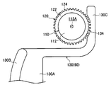
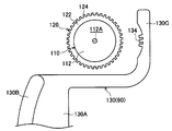
- the lock member 130 As shown in FIG. 9, the lock member 130 is formed in a substantially “ ⁇ ” shape in plan view, and a lower surface of the tip portion 130 ⁇ / b> B of the central portion 130 ⁇ / b> A formed in the arc shape is used as a temporary guide. A plurality of cylindrical tape guides 132 (four in the drawing) are integrally provided so as to be aligned along the arc shape. As shown in detail in FIG. 16, lock gears 134 that mesh with the engagement gear 124 of the rotation position defining member 120 are formed at both ends 130 ⁇ / b> C of the lock member 130.
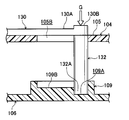
- the lock member 130 is formed on the outer surface of the top wall 105 of the upper cartridge 104 by inserting the tape guide 132 from the outside into the plurality of long hole portions 105 ⁇ / b> B formed in the top wall 105 of the upper cartridge 104. It can be attached. That is, the lock member 130 in which the tape guide 132 is inserted into the long hole portion 105B is slid in the direction of arrow F shown in FIGS.
- the lower end portion 132A of the tape guide 132 is guided in the direction of arrow F by the guide groove 109B, and when the lower end portion 132A comes into contact with the tip end portion of the guide groove 109B, as shown in FIG. As shown, the lock gear 134 meshes with the engagement gear 124. Then, as shown in FIG. 15B, the distal end portion 130B of the central portion 130A of the lock member 130 is pressed downward (in the direction of arrow G) from above to lock the lower end portion 132A of the tape guide 132. Press fit (fit) into the hole 109A.
- the lock member 130 is configured to be easily fixed and arranged at the lock position for locking the rotational position defining member 120 on the top wall 105, and the reels 10, 20 until the magazine 100 is assembled in the drive device 60.
- This is a configuration in which inadvertent rotation is prevented (locked).
- the recording tape T that is unwound from the reel 10 and wound around the outer peripheral surface of the reel hub 22 of the reel 20 is held in a state where a certain amount of tension is applied by the tape guide 132. It is.
- the front end portion 130B of the lock member 130 is lifted upward from the lock hole 109A.
- the lower end 132A of the tape guide 132 is removed.
- the lock member 130 (tape guide 132) is slid along the long hole portion 105B in the direction opposite to the arrow F direction shown in FIGS. 9 and 15A (the direction of arrow E shown in FIG. 20), as shown in FIG. 16B.
- the lock gear 134 may be removed from the engagement gear 124.
- the reel 10 around which the recording tape T is wound and the reel 20 with the free end side of the recording tape T attached to the reel hub 22 are prevented from falling off and non-rotatable by the reel holding mechanism 90 of the second embodiment.
- the lower cartridge 106 is joined to the upper cartridge 104 by the fixing screw 37 and held (fixed) in the magazine 100 (cartridge 102).
- the tip 130B side of the lock member 130 is pulled upward, and the lower end 132A of the tape guide 132 is removed from the lock hole 109A.
- the lower cartridge 106 is removed from the upper cartridge 104.
- the fixing screw 37 may be removed after the lower end 132A of the tape guide 132 is removed from the lock hole 109A.
- the upper cartridge 104 When the lower cartridge 106 is removed from the upper cartridge 104, the upper cartridge 104 is moved onto the bottom plate 61A of the housing 61, and positioning pins 74 protruding from the bottom plate 61A are attached to the bottom surface portion 107 of the upper cartridge 104. Insert into the formed reference hole 107A.
- the reels 10 and 20 are positioned with respect to the rotating members 64 of the drive device 60. That is, the reinforcing portions 18 and 28 of the reel hubs 12 and 22 in the reels 10 and 20 are positioned and arranged on the rotating members 64 of the drive device 60 (arranging step). This state is shown in FIGS. 17B and 19.
- the tape guides 132 of the lock member 130 are arranged between the tape guides 72 of the drive device 60 and on the side away from the recording / reproducing head 70 than the tape guides 72 (arrow F direction side). Therefore, it does not interfere with the tape guide 72 (see FIG. 19). Therefore, the upper cartridge 104 holding the reels 10 and 20 can be easily positioned and arranged on the bottom plate 61A of the housing 61 of the drive device 60.
- the tape guide 132 of the lock member 130 is slid along the long hole portion 105B in the direction of arrow E which is opposite to the direction of arrow F (retracted from the recording tape T). That is, as shown in FIG. 16, the lock gear 134 of the lock member 130 is removed from the engagement gear 124 of the rotational position defining member 120, and the rotational lock of the rotational position defining member 120 is released (release process). Then, the lock member 130 is removed from the upper cartridge 104. Thereby, the locking member 130 does not get in the way in a later process.
- the circumferential positions (rotation angles) of the reel hubs 12 and 22 (reinforcement portions 18 and 28) with respect to the rotation members 64 are accurately positioned, and the boss portions 41 (in the reinforcement portions 18 and 28 of the reel hubs 12 and 22 ( The position of the screw hole portion 40) and the screw boss portion 66 in each rotary member 64 are matched.
- the reels 10 and 20 are slightly rotated (the positions in the circumferential direction of the reels 10 and 20 are adjusted), and the protrusions 68 are fitted into the recesses 48. You may induce to match.
- the tape guide 132 is disposed on the direction side (arrow F direction side) away from the recording / reproducing head 70 with respect to the tape guide 72 of the drive device 60. T is slightly loosened. Therefore, the rotation position defining member 120 can be slightly rotated.
- the engagement gear 124 is formed on the outer peripheral portion of the rotational position defining member 120, when the rotational position defining member 120 is rotated with a finger, the finger is difficult to slide and easily rotates.
- the recording tape T is slightly slackened as described above.
- the reels 10 and 20 are slightly rotated to bring the recording tape T along the tape guide 72.
- the recording tape T guided by the tape guide 132 can be smoothly transferred to the tape guide 72 (the recording tape T can be easily passed when the reels 10 and 20 are assembled to the drive device 60). Can do).
- the vertical position defining member 110 is rotated in the direction opposite to the arrow R direction (the other direction) to hook the connecting portion 45. 118 is released (holding release state), and as shown in FIG. 18A, the vertical position defining member 110 is removed from the upper cartridge 104 (rotational position defining member 120) (releasing step). Then, as shown in FIGS. 21 and 22, the screw 38 is inserted into the screw hole 122 ⁇ / b> A (boss portions 126, 41) of the rotational position defining member 120 and screwed into the screw boss portion 66.
- the boss portions 41 screw hole portions 40 provided in the reinforcing portions 18 and 28 of the reels 10 and 20 and the screw boss portions 66 of the rotating member 64 communicate with each other.
- the reinforcing portion 18 of the reel hub 12 can be fixed to one (first) rotating member 64, and the other (second) rotation.
- the reinforcing portion 28 of the reel hub 22 can be fixed to the member 64 (fixing step).
- the boss portion 126 of the rotational position defining member 120 serves as a guide portion of the screw 38 to the boss portion 41 (screw hole portion 40) and the screw boss portion 66, it is easy to attach the screw 38.
- the shape of the screw 38 may be the one shown in FIG. 18A or the one shown in FIGS.
- the protrusions 42 formed on the lower surfaces of the reinforcing portions 18 and 28 of the reel hubs 12 and 22 come into contact with the upper surface of the rotating member 64, so that the reels 10 and 20 (reinforcement of the reel hubs 12 and 22).
- the portions 18, 28) are fixed with respect to the rotating members 64 with their positions in the height (axis) direction being accurately positioned.
- the reels 10 and 20 are held by the upper cartridge 104 of the magazine 100 and the housing of the drive device 60 is retained. Since it can be assembled into the body 61, the pair of reels 10 and 20 are excellent in assemblability.
- the cartridge 102, the rotation position defining member 120, and the like are reusable, which is preferable for the environment.
- the vertical position defining member 110 is configured by integrally projecting three hook portions 117 at the lower end portion of the boss portion 114 toward the radially outer side at equal intervals. ing.
- the protruding length of the hook portion 117 is shorter than the radius of the through hole 122B of the rotational position defining member 120.
- each reinforcing part 18, 28 in each reel 10, 20 is formed with a hole 30A corresponding to the shape of the boss part 114 from which the hook part 117 is projected. Therefore, the hook portion 117 and the boss portion 114 are inserted into the hole portion 30A, and then, as shown in FIG. 24, the vertical position defining member 110 is rotated by approximately 60 degrees in the circumferential direction (for example, the direction of the arrow R). The hook portion 117 is configured to be easily locked to the lower surfaces of the reinforcing portions 18 and 28.
- the vertical position defining member 110 may be configured to define the vertical position of the reels 10 and 20 by turning the magnetic force on and off. That is, by switching operation of the switching lever 115, a magnetic force is generated in the annular magnetic body 119 provided on the lower surface of the vertical position defining member 110, and the annular members provided on the upper surfaces of the reinforcing portions 18 and 28 of the reels 10 and 20.
- the reels 10 and 20 may be held by the upper cartridge 104 by adsorbing the magnetic metal plate 19.
- the structure used for the well-known magnet stand etc. can be applied to the structure which turns ON / OFF the magnetic force of the magnetic body 119 by switching operation (rotation operation) of the switching lever 115, for example. Further, the recording tape T is not affected by the magnetic field generated by the magnetic body 119 provided on the vertical position defining member 110.
- the method for assembling the reels 10 and 20 and the magazines 80 and 100 according to this embodiment has been described above with reference to the drawings. However, the method for assembling the reels 10 and 20 and the magazines 80 and 100 according to this embodiment are illustrated. However, the present invention is not limited to those described above, and the design can be changed as appropriate without departing from the scope of the present invention.
- the reels 10 and 20 may be accommodated (held) in the magazines 80 and 100 in a state where the recording tape T is wound around each of the reels 10 and 20 and they are not connected.
- the lower cartridges 84 and 106 are not limited to the configuration in which they are completely removed from the upper cartridges 82 and 104, but are configured to slide into the upper cartridges 82 and 104 and the like. Also good.
- the tape guides 88 and 132 as temporary guides are not limited to a configuration in which a plurality of columnar ones are provided. For example, a wall-like (plate-like) one formed in a substantially arc shape in a plan view. A configuration in which a plurality (or one) are provided may be employed.
- a concave portion 48 is formed in the rotating member 64, and convex portions 68 are formed in the reinforcing portions 18 and 28 of the reel hubs 12 and 22, respectively, for positioning in the circumferential direction (positions of the screw hole portion 40 and the screw boss portion 66). May be matched).
- the number of the concave portions 48 (the convex portions 68) and the screw hole portions 40 (the screw boss portions 66) is not limited to three.
- the protruding portion 42 is not limited to the one formed on the lower surface of the screw hole portion 40 and coaxially therewith, but on the concentric circumference different from the screw hole portion 40 on the lower surface of the reinforcing portions 18 and 28. It may be formed.
- the engaged portion is not limited to the illustrated reference holes 87A and 107A, and the engaging portion is not limited to the illustrated positioning pin 74 as well.
- the reference hole 87A in the first embodiment is formed in the bottom surface portion (a part of the bottom wall) of the side wall 86 by making the plate thickness of one side wall 86 larger than the diameter of the positioning pin 74. Also good.
- not the hole 30A (the small cylindrical portion 30) but the concave portion (the small cylindrical portion 30) is formed in the central portion (the rotation center portion of the reel 10) of the reinforcing portions 18 and 28 of the reel hubs 12 and 22. (Not shown).
Landscapes
- Storage Of Web-Like Or Filamentary Materials (AREA)
- Replacement Of Web Rolls (AREA)
Abstract
ドライブ装置に組み込まれる一対のリールのドライブ装置への組込性を確保する。 上カートリッジ(82)に設けられたリール保持機構(90)により、第1リール(10)と第2リール(20)とを上カートリッジ(82)に回転不能に保持する保持工程と、上カートリッジ(82)から下カートリッジ(84)を取り外す取外工程と、リール保持機構(90)によって第1リール(10)及び第2リール(20)を保持した状態の上カートリッジ(82)をドライブ装置(60)へ搬送し、ドライブ装置(60)の一対の回転部材(64)の上に、第1リール(10)と第2リール(20)とをそれぞれ位置決めして配置する配置工程と、リール保持機構(90)による第1リール(10)及び第2リール(20)に対する保持を解除する解除工程と、上カートリッジ(82)をドライブ装置(60)から取り除く除去工程と、第1リール(10)及び第2リール(20)をドライブ装置(60)の各回転部材(64)に固定する固定工程と、を含む組込方法とする。
Description
本発明は、ドライブ装置に一対のリールを取り出し不能に組み込む方法と、そのリールが収容されたマガジンに関する。
従来から、主にコンピューター等の情報記録再生媒体(データバックアップ)として使用される磁気テープ等の記録テープをリールに巻装し、そのリールをケース内に単一で収容してなる記録テープカートリッジが知られている(例えば、特開2010-79989号公報参照)。
この記録テープカートリッジは、ドライブ装置に装填されると、リールから記録テープが引き出され、ドライブ装置の巻取リールに巻き取られる。そして、ドライブ装置の記録再生ヘッドによって、その記録テープに対して情報の書き込み又は読み取りが行われるようになっている。
しかしながら、このようなシステムでは、記録テープカートリッジがドライブ装置に対してリムーバブルであるため、記録テープカートリッジ(記録テープに記録されている情報)に対してセキュリティ対策が必要となる。そのため、ドライブ装置内に直接リールを設け、そのリールが取り出されないようにすることが考えられたが、この場合、一対のリールのドライブ装置に対する組込性を確保する必要がある。
そこで、本発明は、上記事情に鑑み、ドライブ装置に組み込まれる一対のリールのドライブ装置への組込性を確保できるリールの組込方法と、そのリールが収容されたマガジンを得ることを目的とする。
上記の目的を達成するために、本発明に係る第1の態様のリールの組込方法は、上カートリッジと、該上カートリッジから取り外し可能とされた下カートリッジとからなり、それぞれリールハブを備えた第1リール及び第2リールと、前記第1リール及び前記第2リールの少なくとも一方のリールハブの外周面に巻回された記録テープと、を収容したマガジンから、前記第1リール及び前記第2リールをドライブ装置に組み込むための組込方法であって、前記上カートリッジに設けられたリール保持機構により、前記第1リールのリールハブと前記第2リールのリールハブとを、該上カートリッジに回転不能に保持する保持工程と、前記上カートリッジから前記下カートリッジを取り外す取外工程と、前記リール保持機構によって前記第1リール及び前記第2リールの各リールハブを保持した状態の前記上カートリッジを前記ドライブ装置へ搬送し、該ドライブ装置の一対の回転部材の上に、前記第1リールのリールハブと前記第2リールのリールハブとをそれぞれ位置決めして配置する配置工程と、前記リール保持機構による前記第1リール及び前記第2リールの各リールハブに対する保持を解除する解除工程と、前記上カートリッジを前記ドライブ装置から取り除く除去工程と、前記第1リール及び前記第2リールの各リールハブを前記ドライブ装置の各回転部材に固定する固定工程と、を含む。
上記態様によれば、ドライブ装置に組み込まれる第1リール及び第2リールのドライブ装置への組込性を確保することができる。
また、本発明に係る第2の態様のリールの組込方法は、上記態様のリールの組込方法であって、前記配置工程のときに、前記上カートリッジに形成された被係合部に、前記ドライブ装置の係合部を係合させる。
上記態様によれば、第1リール及び第2リールをドライブ装置の一対の回転部材の上に位置決めして配置することが容易にできる。
また、本発明に係る第3の態様のリールの組込方法は、上記態様のリールの組込方法であって、前記記録テープは、前記上カートリッジに備えられた仮ガイドによってガイドされており、前記配置工程又は前記解除工程のときに、前記ドライブ装置の本ガイドへ、前記仮ガイドによってガイドされている前記記録テープを受け渡す。
上記態様によれば、第1リール及び第2リールのドライブ装置への組込性を向上させることができる。
また、本発明に係る第4の態様のリールの組込方法は、上記態様のリールの組込方法であって、前記第1リールのリールハブの両端部及び前記第2リールのリールハブの両端部には、それぞれフランジが設けられており、前記第1リール及び前記第2リールが前記マガジンに収容されているときには、少なくとも前記フランジが、前記マガジンの内面と非接触とされている。
上記態様によれば、マガジンの搬送時等において、そのマガジンの内面によってフランジが変形するおそれがない。したがって、記録テープの幅方向両端部がダメージを受けるおそれがない。
また、本発明に係る第5の態様のマガジンは、それぞれリールハブを備えた第1リール及び第2リールと、前記第1リール及び前記第2リールの少なくとも一方のリールハブの外周面に巻回された記録テープと、ドライブ装置に組み込まれたときに、前記第1リールのリールハブが前記ドライブ装置の第1の組込位置に配置され、前記第2リールのリールハブが前記ドライブ装置の第2の組込位置に配置されるように、前記第1リール及び前記第2リールを位置決めする上カートリッジと、前記上カートリッジに設けられ、前記第1リールのリールハブ及び前記第2リールのリールハブをそれぞれ前記上カートリッジに位置決めされた状態で、該上カートリッジに回転不能に保持するリール保持機構と、を有する。
上記態様によれば、ドライブ装置に組み込まれる第1リール及び第2リールは、上カートリッジに位置決め保持された状態で組み込めるので、ドライブ装置への組込性を確保することができる。
また、本発明に係る第6の態様のマガジンは、上記態様のマガジンであって、前記リール保持機構は、前記第1リールのリールハブに一体に回転するように取り付けられる第1回転位置規定部材と、前記第2リールのリールハブに一体に回転するように取り付けられる第2回転位置規定部材と、前記第1回転位置規定部材及び前記第2回転位置規定部材を回転不能にロックするロック部材と、を有する。
上記態様によれば、マガジンの搬送時等において、第1リール及び第2リールが不用意に回転するのを確実に阻止することができる。
また、本発明に係る第7の態様のマガジンは、上記態様のマガジンであって、前記ロック部材は、前記記録テープをガイドする仮ガイドを有し、前記上カートリッジが前記ドライブ装置に組み込まれて前記第1回転位置規定部材及び前記第2回転位置規定部材に対する前記ロック部材のロックが解除され、前記仮ガイドが前記記録テープから退避されることで、該記録テープが前記ドライブ装置の本ガイドへ受け渡し可能になるように構成されている。
上記態様によれば、第1リール及び第2リールのドライブ装置への組込性を向上させることができる。
また、本発明に係る第8の態様のマガジンは、上記態様のマガジンであって、前記上カートリッジの下部を開放可能に構成され、該上カートリッジとで前記第1リール及び前記第2リールを収容する下カートリッジを有し、前記ロック部材は、前記仮ガイドが前記下カートリッジに設けられたガイド保持部に保持されることで、前記第1回転位置規定部材及び前記第2回転位置規定部材に対するロック位置に固定される。
上記態様によれば、第1リール及び第2リールに対する回転ロックが簡単にできる。
また、本発明に係る第9の態様のマガジンは、上記態様のマガジンであって、前記ロック部材は、前記仮ガイドが前記記録テープから退避され、該記録テープが前記ドライブ装置の本ガイドへ受け渡された後、取り外せるように構成されている。
上記態様によれば、記録テープが仮ガイドからドライブ装置の本ガイドへ受け渡された後の作業において、ロック部材が邪魔にならないようにできる。
また、本発明に係る第10の態様のマガジンは、上記態様のマガジンであって、前記上カートリッジの下部を開放可能に構成され、該上カートリッジとで前記第1リール及び前記第2リールを収容する下カートリッジを有するとともに、前記第1リールのリールハブの両端部及び前記第2リールのリールハブの両端部には、それぞれフランジが設けられており、前記リール保持機構は、前記フランジが前記上カートリッジの内面及び前記下カートリッジの内面に非接触となるように、前記第1リールのリールハブの上下方向の位置を規定する第1上下位置規定部材と、前記第2リールのリールハブの上下方向の位置を規定する第2上下位置規定部材と、を有する。
上記態様によれば、マガジンの搬送時等において、上カートリッジの内面や下カートリッジの内面によってフランジが変形するおそれがない。したがって、記録テープの幅方向両端部がダメージを受けるおそれがない。
また、本発明に係る第11の態様のマガジンは、上記態様のマガジンであって、前記第1上下位置規定部材及び前記第2上下位置規定部材は、一方向に回転させることで、前記第1リール及び前記第2リールの各リールハブの上下方向の位置を規定する保持状態を取り、前記一方向又は他方向に回転させることで、前記各リールハブの上下方向の位置規定を解除する保持解除状態を取る構成とされている。
上記態様によれば、第1リール及び第2リールの上下方向の位置を簡単に規定することができる。
また、本発明に係る第12の態様のマガジンは、上記態様のマガジンであって、前記第1リール及び前記第2リールの各リールハブの内周面側には、磁性金属が設けられており、前記第1上下位置規定部材及び前記第2上下位置規定部材は、前記各リールハブの磁性金属を磁力により吸着することで、該各リールハブの上下方向の位置を規定する保持状態を取り、前記各リールハブの磁性金属の磁力による吸着を解除することで、該各リールハブの上下方向の位置規定を解除する保持解除状態を取る構成とされている。
上記態様によれば、第1リール及び第2リールの上下方向の位置を簡単に規定することができる。
また、本発明に係る第13の態様のマガジンは、上記態様のマガジンであって、前記上カートリッジは、前記ドライブ装置に設けられた係合部に係合し、該ドライブ装置の前記第1の組込位置及び前記第2の組込位置に対して、それぞれ前記第1リール及び前記第2リールを位置決めする被係合部を有する。
上記態様によれば、第1リール及び第2リールをドライブ装置の各組込位置に位置決めして配置することが容易にできる。
また、本発明に係る第14の態様のマガジンは、上記態様のマガジンであって、前記第1の組込位置及び前記第2の組込位置には、それぞれ回転部材が配置され、前記リールハブ及び前記回転部材の何れか一方に形成された凸部と、前記リールハブ及び前記回転部材の何れか他方に形成され、前記凸部に嵌合される凹部と、で前記回転部材に対する前記リールハブの周方向の位置を規定する位置決め部が構成されている。
上記態様によれば、ドライブ装置の回転部材に対して、第1リール及び第2リールの各リールハブの周方向の位置を位置決めすることができる。これにより、各リールハブに設けられたビス孔部の位置と、回転部材に設けられたビスボス部の位置を一致させることが容易にできる。
また、本発明に係る第15の態様のマガジンは、上記態様のマガジンであって、前記上カートリッジの下部を開放可能に構成され、該上カートリッジとで前記第1リール及び前記第2リールを収容する下カートリッジを有し、前記下カートリッジは、前記上カートリッジ側に設けられた締結具によって該上カートリッジに固定されることで、前記第1リール及び前記第2リールを支持する構成である。
上記態様によれば、上カートリッジに保持されている第1リール及び第2リールを、マガジン内において固定することができる。
以上のように、本発明によれば、ドライブ装置に組み込まれる一対のリールのドライブ装置への組込性を確保できるリールの組込方法と、そのリールが収容されたマガジンを提供することができる。
以下、本発明に係る実施の形態について、図面を基に詳細に説明する。なお、説明の便宜上、図1、図2における矢印UPを上方向、矢印DOを下方向とし、本実施形態に係る第1リールとしてのリール10及び第2リールとしてのリール20の回転軸方向を上下方向(高さ方向)とする。
本実施形態に係るリール10、20は、例えばポリカーボネート(PC)等の合成樹脂製とされており、図1で示すように、ドライブ装置60の筐体61(図1では底板61Aと3本の支柱61Bのみが示されている)内に一対で設けられている。
すなわち、リール10は、後述する記録テープTの繰り出し用とされ、リール20は、後述する記録テープTの巻き取り用とされており、リール10から繰り出された記録テープTが、リール20に巻き取られつつ、記録再生ヘッド70に摺接するようになっている。つまり、この記録再生ヘッド70によって、その記録テープTに対してデータが記録されたり、その記録テープTに記録されたデータが再生されたりするようになっている。
なお、記録再生ヘッド70の両側における底板61Aには、複数個(図示のものは2個ずつで計4個)のテープガイド(本ガイド)72が回転自在に設けられており、リール10から引き出され、リール20に巻き取られる記録テープTが、各テープガイド72によって、ガイドされるようになっている。
次に、そのドライブ装置60へ一対のリール10、20を組み込むための第1実施形態に係るマガジン80について説明する。図2~図4で示すように、このマガジン80は、底壁85の一部(以下「底面部87」という)を備えた上カートリッジ82と、上カートリッジ82に対して取り外し可能に設けられた底壁85を構成する下カートリッジ84と、を有している。
すなわち、上カートリッジ82は、天壁83の周縁部に側壁86が一体に立設された略矩形箱状に形成されており、下カートリッジ84(底壁85)は、平板状に形成されている。そして、下カートリッジ84(底壁85)の所定位置には、各リール10、20における各リールハブ12、22の各補強部18、28を外部へ露出させるための一対の開口部85Aが形成されている。
なお、上カートリッジ82及び下カートリッジ84の材質は特に限定されない。例えば、板金等の金属材料で成形してもよいし、リール10、20と同じPC等の合成樹脂材料で成形してもよい。また、下カートリッジ84を上カートリッジ82に取り外し可能に設ける構成は、任意の構成を採用して構わない。
例えば、底面部87の両側における側壁86の下端部に溝部(図示省略)を形成し、その溝部内に下カートリッジ84の互いに対向する辺縁部を底面部87とは反対側から進入させて、その底面部87側へスライドさせることにより、上カートリッジ82に対して下カートリッジ84を装着可能にするなどの構成を採用すればよい。
また、この上カートリッジ82の側壁86には、繰り出し用のリール10に未記録の記録テープTを巻回するときに、後述する巻回装置50から供給される未記録の記録テープTをマガジン80内に進入させ、その自由端をリールハブ12の外周面に取り付け、その記録テープTをリールハブ12に巻回させるための開口部(図示省略)が形成されている。そして、その開口部を閉塞する閉塞部材(図示省略)が、側壁86に対して着脱可能に設けられている。
また、上カートリッジ82の天壁83の内面における所定位置、即ち平面視でドライブ装置60のテープガイド72よりも各リール10、20(記録再生ヘッド70)から、その回転軸方向と直交する方向における外方側へ離れた位置(図1参照)には、下方に向けて円柱状のテープガイド(仮ガイド)88が複数個(図示のものは4個)突設されている。
また、上カートリッジ82の天壁83には、各リール10、20を保持するリール保持機構90が一対で設けられている。第1実施形態に係るマガジン80のリール保持機構90は、後述するリールハブ12、22の内周面側に上方から挿入され、その内周面を径方向外側へ押圧して保持する爪部92と、その爪部92を回転可能に支持するとともに、その爪部92による押圧状態を解除可能に構成された把持部94と、を有している。
そして、各リール保持機構90で保持された状態のリール10、20の上フランジ14、24及び下フランジ16、26は、マガジン80の上カートリッジ82及び下カートリッジ84の内面に非接触とされている(リール10、20の上フランジ14、24及び下フランジ16、26と、マガジン80の上カートリッジ82及び下カートリッジ84の内面との間には空隙が形成されている)。
これにより、マガジン80の搬送時等において、その上カートリッジ82及び下カートリッジ84の内面によって、特にリール10の上フランジ14及び下フランジ16が変形されるのが防止される構成である。つまり、これにより、リール10に巻回されている記録テープTの幅方向両端部(以下「エッジ」という)にダメージが発生し難くなる構成である。
また、上カートリッジ82の底面部87には、ドライブ装置60の位置決めピン(係合部)74(図1参照)が挿通される基準孔(被係合部)87Aが、複数個(図示のものは2個)所定位置に形成されている。これにより、ドライブ装置60に対するマガジン80の配設位置が規定される(位置決めされる)構成である。
次に、リール10、20について、図6~図8を基に説明する。マガジン80に収容され、そのマガジン80からドライブ装置60へ供給されるリール10は、軸心部を構成する略円筒状のリールハブ12と、その上端部側に設けられる環状の上フランジ14と、その下端部側に設けられる環状の下フランジ16と、リールハブ12の内周面における高さ(軸)方向略中央部に一体に連設された補強部18と、を含んで構成されている。
同様に、マガジン80に収容され、そのマガジン80からドライブ装置60へ供給されるリール20も、軸心部を構成する略円筒状のリールハブ22と、その上端部側に設けられる環状の上フランジ24と、その下端部側に設けられる環状の下フランジ26と、リールハブ22の内周面における高さ(軸)方向略中央部に一体に連設された補強部28と、を含んで構成されている。
そして、リール10におけるリールハブ12の外周面には、情報記録再生媒体としての磁気テープ等の記録テープTが巻回されるようになっており、上フランジ14及び下フランジ16によって、巻回された記録テープTの幅方向の端部が保持されるようになっている。なお、リール10から繰り出された記録テープTは、リール20におけるリールハブ22の外周面に巻回され、上フランジ24及び下フランジ26によって、その幅方向の端部が保持されるようになっている。
また、本実施形態における「略円筒状」には、記録テープTが巻回される各リールハブ12、22の外周面(巻面)の形状が太鼓形状等に形成されている概ね円柱状であるもの、及び各リールハブ12、22の内周面側にリブ等が突設されている完全な円筒状でない中空状であるものなども含まれる。
なお、以下においては、リール20はリール10と同一の構成であるため、主にリール10について説明する。図6~図8で示すように、上フランジ14の内周縁部には、下方へ所定高さ延在する円筒部15が一体に形成されており、下フランジ16の内周縁部には、上方へ所定高さ延在する円筒部17が一体に形成されている。
円筒部15の内周面及び円筒部17の内周面には、それぞれ径方向内側(リール10の回転中心部)に向かって突出する平板状の張出部32、34が等間隔に複数個(例えば6個ずつ)、平面視で互いに重ならない位置に形成されており、各張出部32、34には、それぞれ円形状の孔部32A、34Aが形成されている。
また、リールハブ12の補強部18における外周縁部側(リールハブ12の内周面側)の上面及び下面には、内周面に雌ネジが切られた円筒状のビスボス部33、35が、それぞれ等間隔に複数個(例えば6個ずつ)、平面視で互いに重ならない位置に突設されている。そして、各ビスボス部33、35と各張出部32、34の孔部32A、34Aとが互いに連通されるようになっている。
したがって、上方から上フランジ14の張出部32の孔部32Aに挿入されたビス36がビスボス部33に螺合され、下方から下フランジ16の張出部34の孔部34Aに挿入されたビス36がビスボス部35に螺合されることにより(図8参照)、上フランジ14及び下フランジ16が、それぞれリールハブ12に一体的に取り付けられるようになっている。
また、円筒部15及び円筒部17よりも径方向内側における補強部18の同心円周上(平面視で特定のビスボス部33とビスボス部35との間)には、後述するドライブ装置60の回転部材64に補強部18を固定するためのビス孔部40が等間隔に3個形成されており、そのビス孔部40の下面側には、ビス孔部40と同軸となる(ビス孔部40に連通する)円筒状に下方へ向けて突出された突出部42が一体に形成されている(図8参照)。
また、図6、図7で示すように、ビス孔部40(ビスボス部33、35)よりも径方向内側における補強部18には、側面視で上フランジ14の上面から突出しない程度に上方へ向かって突出された環状上面部18Aが形成されている。そして、その環状上面部18Aよりも径方向内側における補強部18には、側面視で下フランジ16の下面から突出しない程度に下方へ向かって突出された環状下面部18Bが形成されている。
そして更に、その環状下面部18Bよりも径方向内側における補強部18の中央部(リール10の回転中心部)には、側面視で環状上面部18Aから上方へ突出しない程度に上方へ向かって突出された小円筒部30が形成されている。この小円筒部30の孔部30Aに、後述するドライブ装置60の軸出部62や巻回装置50の軸出部52が挿入(嵌合)されるようになっている。
また、環状上面部18Aの下面側で、かつ、その径方向外側部分には、リールギア44が環状に形成されている。このリールギア44は、高さ(軸)方向に延在する複数の縦リブ44Aで構成されており、図8で示す巻回装置50における駆動ギア54の複数の縦リブ54Aと着脱自在に噛合可能となっている。
そして、その縦リブ44Aの間の所定位置(補強部18の同心円周上)には、図6、図7で示す後述する回転部材64の凸部68が嵌合する凹部48(図8参照)が等間隔に(ビス孔部40同士の中間に配置されるように)3個形成されている。また、図8で示すように、リールギア44よりも径方向内側に形成されている環状下面部18Bには、磁性金属で環状に形成されたリールプレート46がインサート成形によって固着されている。
このリールプレート46の中央部に形成されている孔部46Aは、小円筒部30の孔部30Aと連通されるようになっており、その孔部46Aの内径は、孔部30Aの内径と同一か、それよりも若干大径とされている。そして、後述するドライブ装置60の軸出部62や巻回装置50の軸出部52が、その孔部46Aを通って孔部30Aに挿入可能となっている。
ここで、上記したように、リール10のリールギア44には、巻回装置50の駆動ギア54が噛合可能となっている。すなわち、図8で示すように、巻回装置50の駆動ギア54は、径方向外側に向かって放射状に延在する縦リブ54Aを複数有しており、その駆動ギア54の回転中心部には、円柱状の軸出部52が上方に向かって突設されている。そして、その軸出部52よりも径方向外側で、かつ駆動ギア54よりも径方向内側には、環状のマグネット56が固着されている。
したがって、リール10の製造時、そのリールハブ12の外周面に未記録の記録テープTを巻回するときには、マガジン80の下カートリッジ84(底壁85)に形成されている開口部85Aから、駆動ギア54を進入させる。すると、軸出部52が孔部46Aを通って孔部30Aに挿入されるとともに、リールプレート46がマグネット56によって吸着され、駆動ギア54がリールギア44に噛合する。そして、巻回装置50の駆動ギア54が回転することにより、リール10のリールハブ12に未記録の記録テープTが巻回される。
一方、図5~図7で示すように、ドライブ装置60には、駆動源としてのモーター(図示省略)が配置されており、そのモーターの回転軸(図示省略)から伝達ギア(図示省略)を介して回転駆動力が伝達される一対の樹脂製又は金属製の回転部材64が、ドライブ装置60の筐体61(底板61A)に形成された一対の開口部58内にそれぞれ回転可能に設けられている。
各回転部材64には、各リール10、20におけるリールハブ12、22の補強部18、28が、図7で示すビス38によって固定されるようになっている。すなわち、各回転部材64の同心円周上には、各補強部18、28のビス孔部40に挿入されたビス38が螺合されるビスボス部66が等間隔に3個形成されている。
そして、各リールハブ12、22の補強部18、28に形成された凹部(位置決め部)48に嵌合する凸部(位置決め部)68が、各回転部材64のビスボス部66同士の中間に配置されるように、等間隔に3個突設されている。そして更に、各回転部材64の中央部(回転中心部)には、リールプレート46の孔部46Aを通って補強部18、28(小円筒部30)の孔部30Aに挿入される円柱状の軸出部62が上方に向かって突設されている。
したがって、記録テープTが巻回されたリール10と、記録テープTの自由端がリールハブ22の外周面に取り付けられたリール20を、ドライブ装置60の各回転部材64に固定するときには、各軸出部62が各孔部46Aを通って各孔部30Aに挿入される。そして、各凹部48に各凸部68が嵌合されることにより、各ビス孔部40と各ビスボス部66との位置が一致され、上方からビス38が各ビス孔部40に挿入されて、各ビスボス部66に螺合されることにより、各リールハブ12、22と各回転部材64とが一体的に固定される。
以上のような構成において、次にその作用(ドライブ装置60へのリール10、20の組込方法)について説明する。まず、リール10の製造時、そのリールハブ12の外周面に未記録の記録テープTを巻回する際には、記録テープTが巻回されていないリール10を巻回装置50に装着する。
すなわち、マガジン80内に収容され、リール保持機構90によって保持されているリール10において、下カートリッジ84の開口部85Aから露出されているリールギア44を巻回装置50の駆動ギア54に噛合させる。
このとき、巻回装置50の軸出部52がリールプレート46の孔部46Aを通り、補強部18(小円筒部30)の孔部30Aに挿入される。そして、巻回装置50のマグネット56がリールプレート46を吸着する。したがって、リール10のリールギア44は、巻回装置50の駆動ギア54と位置精度良く噛合する。
リールギア44と駆動ギア54とが位置精度良く噛合したら、把持部94を操作して、リール保持機構90のリール10に対する保持を解除し、上カートリッジ82の側壁86から閉塞部材(図示省略)を外し、その側壁86に形成された開口部(図示省略)から、未記録の記録テープTの自由端を進入させ、その自由端をリールハブ12の外周面に取り付ける。
そして、駆動ギア54を一方向に高速で回転させることにより、リール10のリールハブ12に未記録の記録テープTを巻回する。リール10のリールハブ12に未記録の記録テープTを巻回させる巻回工程が終了したら、その記録テープTの終端部分をテープガイド88に沿わせつつ、その記録テープTの終端側の自由端をリール20のリールハブ22の外周面に取り付ける。
そして、各把持部94を操作し、各リール保持機構90の各爪部92により、各リールハブ12、22の内周面を径方向外側へ押圧し、各リール10、20を各リール保持機構90によって上カートリッジ82に脱落防止かつ回転不能に保持する(保持工程)。そして、リール10のリールギア44を巻回装置50の駆動ギア54から取り外し、マガジン80を巻回装置50から取り外す。
なお、このとき、各リール10、20の各上フランジ14、24及び各下フランジ16、26は、上カートリッジ82及び下カートリッジ84の内面(特に側壁86の内面)に非接触とされている。したがって、マガジン80の搬送時等において、そのマガジン80に(落下等により)衝撃が加わっても、マガジン80内に収容されている特にリール10の上フランジ14及び下フランジ16に、その衝撃が伝達されることが抑制又は防止される。よって、リール10に巻回されている記録テープTにエッジダメージは発生し難い。
こうして、リール10に未記録の記録テープTが巻回されたら、図5Aで示すように、そのマガジン80をドライブ装置60へ搬送する。そして、図5Bで示すように、下カートリッジ84(底壁85)を取り外し(取外工程)、ドライブ装置60の位置決めピン74を上カートリッジ82の底面部87に形成された基準孔87Aに挿通させる。これにより、ドライブ装置60の各回転部材64に対して、各リール10、20が位置決めされる。
すなわち、各リール10、20におけるリールハブ12、22の補強部18、28が、ドライブ装置60の各回転部材64の上に位置決めされて配置される(配置工程)。なお、このとき、上カートリッジ82の天壁83の内面に突設されているテープガイド88は、ドライブ装置60のテープガイド72よりも、各リール10、20の回転軸方向と直交する方向における外方側に配置されていてテープガイド72に干渉しないので(図1参照)、各リール10、20を保持している上カートリッジ82を、ドライブ装置60の筐体61の底板61A上へ位置決めして配置することが容易にできる。
さて、各リールハブ12、22の補強部18、28が、各回転部材64の上に配置されると、各回転部材64の軸出部62が各リール10、20におけるリールプレート46の孔部46Aに挿通され、各補強部18、28(小円筒部30)の孔部30Aに挿入される。これにより、各回転部材64に対する各リールハブ12、22(補強部18、28)の径方向の位置が精度良く位置決めされる(センタリングされる)。
また、各回転部材64の凸部68が各リールハブ12、22の補強部18、28に形成された凹部48に嵌合される。したがって、各回転部材64に対する各リールハブ12、22(補強部18、28)の周方向の位置(回転角度)が精度良く位置決めされ、各リールハブ12、22の補強部18、28におけるビス孔部40と、各回転部材64におけるビスボス部66との位置が一致される。なお、このとき、把持部94によってリール10、20を僅かに回転させ、凹部48に凸部68を嵌合させるように誘導してもよい。
こうして、回転部材64に対するリールハブ12、22の位置が規定されたら、把持部94を操作して、各リールハブ12、22の内周面に対する爪部92の押圧(保持)を解除し(解除工程)、図5Cで示すように、上カートリッジ82をドライブ装置60の筐体61内(底板61A上)から取り除く(除去工程)。そして、一方の(第1の)回転部材64にリールハブ12の補強部18を固定するとともに、他方の(第2の)回転部材64にリールハブ22の補強部28を固定する(固定工程)。
すなわち、図7で示すように、ビス38をビス孔部40に挿入し、ビスボス部66に螺合する。このとき、ビス孔部40の下面に形成(突設)されている突出部42が回転部材64の上面に当接するので、各リール10、20(各リールハブ12、22の補強部18、28)は、各回転部材64に対して、その高さ(軸)方向の位置が精度良く位置決めされて固定される。
また、上カートリッジ82をドライブ装置60の筐体61内(底板61A上)から取り除いたとき、図1で示したように、テープガイド88は、テープガイド72よりも外方側(各リール10、20から、その回転軸方向と直交する方向へ離れる方向側であり、記録再生ヘッド70から同方向側に離れた位置)に配置されているので、記録テープTは僅かに弛んだ状態となっている。
したがって、上カートリッジ82を取り除いたら、回転部材64を僅かに回転させて、記録テープTをリールハブ12又はリールハブ22に僅かに巻回し、テープガイド72に沿わせる。これにより、上カートリッジ82のテープガイド88にガイドされていた記録テープTを、ドライブ装置60のテープガイド72にスムーズに受け渡すことができる(各リール10、20のドライブ装置60への組み付け時に記録テープTを容易にパスさせることができる)。
このように、第1実施形態に係るマガジン80を使用したリール10、20の組込方法によれば、マガジン80の上カートリッジ82によって各リール10、20を保持した状態で、ドライブ装置60の筐体61内に組み込めるので、一対のリール10、20の組込性に優れる。しかも、その上カートリッジ82及び下カートリッジ84等は再使用可能であるため、環境にも好ましい。
なお、巻き取り用のリール20には、未記録の記録テープTが巻回される可能性が少ない。そのため、製造の仕方によっては、巻き取り用のリール20には、リールギア44とリールプレート46を設けなくてもよい。
次に、第2実施形態に係るマガジン100について説明する。なお、上記第1実施形態において説明した部位と同等の部位には、同じ符号を付して詳細な説明(作用も含む)を省略する。
また、本発明に係る「第1上下位置規定部材」と「第2上下位置規定部材」は同じものであるため、以下においては「第1」、「第2」を区別する記載を省略する。同様に、本発明に係る「第1回転位置規定部材」と「第2回転位置規定部材」も同じものであるため、以下においては「第1」、「第2」を区別する記載を省略する。
図9、図10で示すように、このマガジン100は、下方側が開放された略矩形箱状の上カートリッジ104と、上カートリッジ104の開放された下方側を閉塞可能な平板状の下カートリッジ106とからなるカートリッジ102を有している。上カートリッジ104は樹脂製又は金属製とされ、下カートリッジ106は樹脂製とされている。そして、このマガジン100のカートリッジ102内には、一対のリール10、20が収容されており、各リール10、20は、カートリッジ102の長手方向に並んで配置されている。
また、このマガジン100には、カートリッジ102内に収容されたリール10、20の上下方向(高さ方向)の位置を規定する樹脂製の上下位置規定部材110と、周方向(回転方向)の位置を規定する樹脂製の回転位置規定部材120と、搬送時等において(ドライブ装置60に組み込まれるまで)、回転位置規定部材120(リール10、20)の回転をロックする樹脂製のロック部材130と、が備えられている。そして、これら上下位置規定部材110、回転位置規定部材120、ロック部材130により、第2実施形態に係るマガジン100のリール保持機構90が構成されている。
図10で示すように、上カートリッジ104の天壁105には、リール10、20毎に回転位置規定部材120及び上下位置規定部材110等を挿通させるための円形状の開口部105Aが一対で形成されている。そして、上カートリッジ104の天壁105には、ロック部材130の後述する複数本(図示のものは4本)のテープガイド132を挿通させるための長孔部105Bが、リール10、20の並び方向(カートリッジ102の長手方向)と直交する方向を長手方向として同数(図示のものは4つ)、カートリッジ102の長手方向に並んで形成されている。
なお、第2実施形態に係るマガジン100の上カートリッジ104には、図17で示すように、ドライブ装置60の位置決めピン74に挿通させる基準孔(被係合部)107Aを有する底面部107が形成されており、この底面部107と下カートリッジ106とで、カートリッジ102の底壁を構成するようになっている。
また、第2実施形態に係るマガジン100の下カートリッジ106には、図10で示すように、各リール10、20の補強部(各リールハブ12、22の内周面側を閉塞するような略円板状の補強部)18、28を下方から支持する環状の支持台108Aと、その支持台108A内における各リール10、20の回転中心位置に、後述する固定ビス37が螺合される円筒状のビスボス部108Bと、を有するベース部108が一体に形成されている。
そして、この下カートリッジ106には、図15で詳細に示すように、テープガイド132の外径よりも若干小径とされ、その下端部132Aが圧入(保持)されることでロック部材130を移動不能にロックする円形状のロック穴(ガイド保持部)109Aと、ロック穴109Aと同径で連続して形成され、テープガイド132が長孔部105Bに沿って移動する際に、そのテープガイド132の下端部132Aをガイドする略楕円形状のガイド溝109Bと、を有するガイドロック部109が一体に形成されている。
また、図11、図12で示すように、回転位置規定部材120は、外径が開口部105Aよりも大径とされ、外周部の全周に亘って係合ギア124が形成された円板状の本体部122と、本体部122の同心円周上に等間隔に複数(例えば3個)形成されたビス孔部122Aと同軸になるように、本体部122の下面に突設された円筒状のボス部126と、を有している。
各ボス部126の下端部の径方向外側には、補強部18、28の後述するボス部41の外周面に嵌合する底面視半円弧状の延設部126Aが形成されている。つまり、延設部126Aよりも径方向内側のボス部126の下端面126Bが、ボス部41の上面に当接するようになっており、延設部126Aがボス部41の外周面41Aを被覆するようになっている。そして、本体部122の中心部には、上下位置規定部材110の後述するボス部114と係止部116を挿通させるための貫通孔122Bが形成されている。
また、図12で示すように、上下位置規定部材110は、外径が回転位置規定部材120の本体部122よりも小径(開口部105Aと略同径)とされた円板状の本体部112と、本体部112の中心位置に形成されたビス孔部112Aと同軸になるように、本体部112の下面中央に突設された円筒状のボス部114と、本体部112の下面で、かつ本体部112の同心円周上に等間隔に複数(例えば3個)突設された係止部116と、を有している。
各係止部116の下端部には、周方向で、かつ一方向に延在するフック部118が一体に形成されている。そして、このフック部118を備えた係止部116及びボス部114が、回転位置規定部材120の貫通孔122Bに挿通されるとともに、補強部18、28にそれぞれ形成されている複数(この場合は等間隔に3個)の円弧状の長孔部43及び孔部30Aに、それぞれ挿通されるようになっている。
ここで、各長孔部43に挿通された各係止部116のフック部118は、図13で示すように、フック部118の延在している一方向(図13で示す矢印R方向)に、後述する連結部45の周方向を向く側面に係止部116が当接するまで回転されることで、その連結部45の下面に簡単に係止されるようになっている。
これにより、図11で示すように、各上下位置規定部材110が、各リール10、20の補強部18、28との間に各回転位置規定部材120を挟んだ状態で、各リール10、20に取り付けられ(保持状態とされ)、各リール10、20が、開口部105Aよりも大径とされた本体部122を備えた回転位置規定部材120によって、上カートリッジ104の天壁105に吊下された状態に保持される構成である。
そして、この状態で、締結具としての固定ビス37が上下位置規定部材110の本体部112における中心位置に形成されたビス孔部112Aに挿通され、下カートリッジ106のベース部108におけるビスボス部108Bに螺合されることにより、上カートリッジ104と下カートリッジ106とが接合され、カートリッジ102内において、各リール10、20が上下方向の位置を規定された状態で固定されるようになっている。
つまり、これにより、各リール10、20が、上下位置規定部材110及び回転位置規定部材120によって上カートリッジ104に位置決め保持されるだけではなく、下カートリッジ106のベース部108(支持台108A)によって下方から支持され、マガジン100(カートリッジ102)内において、各上フランジ14、24が上カートリッジ104の天壁105の内面に非接触となり、かつ、各下フランジ16、26が下カートリッジ106の内面に非接触となる構成である。
ここで、第2実施形態におけるリール10、20の補強部18、28の形状について説明する。なお、リール10の補強部18とリール20の補強部28は同じ形状であるため、第2実施形態においても、リール10の補強部18を例に採って説明する。図12、図13で示すように、この第2実施形態で示すリール10の補強部18は、第1実施形態で示すリール10の補強部18とは、中心部分の形状が異なっている。
すなわち、補強部18の中心部分には、小円筒部30と、小円筒部30よりも大径とされた大円筒部31とが設けられており、小円筒部30の外周面と大円筒部31の内周面とが、等間隔に3箇所設けられた連結部45によって一体に連結されて構成されている。そして、大円筒部31の上面が環状上面部18Aとされ、下面が環状下面部18Bとされている。
また、小円筒部30と大円筒部31とは、補強部18の上面及び下面において同じ高さに形成されており、連結部45は、補強部18の上面側では小円筒部30及び大円筒部31と同じ高さに形成されている。すなわち、この連結部45は、補強部18の下面側では小円筒部30及び大円筒部31よりも低い高さに形成されており、その下面に係止されるフック部118が環状下面部18Bと略面一になる(下カートリッジ106を上カートリッジ104に接合したときに、フック部118が支持台108Aを相対的に押圧しない)ように構成されている。
そして、補強部18の下面側で、かつ各連結部45の径方向外側には、側面視で環状下面部18Bよりも下方へ突出する円筒状の突出部(ボス部)42が一体に形成され、補強部18の上面側で、かつ各連結部45の径方向外側には、側面視で環状上面部18Aよりも高さの低い円筒状のボス部41が一体に形成されている。なお、このボス部41(突出部42)の内部がビス孔部40とされている。
補強部18の上面側において、各ボス部41の高さは、各延設部126Aの高さ(下端面126Bからの突出高さ)と略同一とされており、各延設部126Aが、環状上面部18Aよりも径方向外側に張り出すボス部41の外周面に嵌合することにより、回転位置規定部材120が、リール10の補強部18に対して回り止めされ、そのリール10と一体に回転可能とされている。
つまり、この回転位置規定部材120が、ロック部材130によって、その回転が規制されることで、リール10の不用意な回転が阻止されるようになっている。なお、この回転位置規定部材120のボス部126は、ドライブ装置60の回転部材64へリール10、20を取り付けるときに、そのリール固定用のビス38をボス部41(ビス孔部40)へ案内するガイド部にもなっている。
また、図14で示すように、リール10の補強部18の下面で、かつ突出部42同士の中間には、ドライブ装置60の回転部材64に突設された凸部(位置決め部)68が嵌合される凹部(位置決め部)48が形成されている。なお、第1実施形態におけるリール10の凹部48は、下方へ向けて開口するように形成されているが、第2実施形態におけるリール10の凹部48は、径方向外側へ向けて開口するように形成されている。
また、第2実施形態に係るマガジン100(カートリッジ102)内には、予め記録テープTが巻回されたリール10と、その記録テープTの自由端側がリールハブ22の外周面に取り付けられたリール20とが収容されるようになっている。そのため、下カートリッジ106には、開口部が形成されず、かつリール10には、巻回装置50に噛合するリールギア44やリールプレート46が設けられない構成になっている。
次に、ロック部材130について説明する。このロック部材130は、図9で示すように、平面視略「Ω」字状に形成されており、その円弧状に形成された中央部130Aの先端部130Bの下面には、仮ガイドとしての円柱状のテープガイド132が複数本(図示のものは4本)、その円弧形状に沿って並ぶように一体に突設されている。そして、図16で詳細に示すように、ロック部材130の両端部130Cには、回転位置規定部材120の係合ギア124と噛合するロックギア134が形成されている。
ここで、このロック部材130は、テープガイド132が上カートリッジ104の天壁105に形成された複数の長孔部105Bに外部から挿通されることにより、その上カートリッジ104の天壁105の外面に取り付けられるようになっている。すなわち、テープガイド132を長孔部105Bへ挿通させたロック部材130を、図9、図15Aで示す矢印F方向にスライドさせる。
すると、テープガイド132の下端部132Aは、図15Aで示すように、ガイド溝109Bによって矢印F方向にガイドされ、その下端部132Aがガイド溝109Bの先端部に当接したときに、図16Aで示すように、ロックギア134が係合ギア124に噛合するようになっている。そして、図15Bで示すように、ロック部材130の中央部130Aの肉厚とされた先端部130Bを下方に向けて(矢印G方向へ)上方から押圧し、テープガイド132の下端部132Aをロック穴109Aに圧入(嵌合)させる。
これにより、ロック部材130が、天壁105において、回転位置規定部材120をロックするロック位置に簡単に固定配置される構成であり、マガジン100がドライブ装置60に組み込まれるまで、各リール10、20の不用意な回転が阻止される(ロックされる)構成である。そして、図9で示すように、リール10から繰り出され、リール20のリールハブ22の外周面に巻回された記録テープTが、テープガイド132によってある程度の張力が付与された状態で保持される構成である。
なお、マガジン100内のリール10、20をドライブ装置60に組み込むために、ロック部材130による回転ロックを解除する際には、まず、ロック部材130の先端部130Bを上方へ引き上げ、ロック穴109Aからテープガイド132の下端部132Aを外す。そして、ロック部材130(テープガイド132)を長孔部105Bに沿って図9、図15Aで示す矢印F方向とは反対方向(図20で示す矢印E方向)にスライドさせ、図16Bで示すように、係合ギア124からロックギア134を外せばよい。
次に、このようなマガジン100を使用した場合のドライブ装置60へのリール10、20の組込方法(作用)について説明する。記録テープTが巻回されたリール10と、記録テープTの自由端側がリールハブ22に取り付けられたリール20は、第2実施形態のリール保持機構90により、上カートリッジ104に脱落防止かつ回転不能に保持され(保持工程)、固定ビス37により下カートリッジ106が上カートリッジ104に接合されることで、マガジン100(カートリッジ102)内に収容(固定)されている。
したがって、マガジン100の搬送(輸送)時において、リール10に巻回されている記録テープTにエッジダメージは発生し難い。搬送(輸送)されて来たマガジン100をドライブ装置60へ組み込むときには、まず、図17A、図17Bで示すように、下カートリッジ106を取り外す(取外工程)。すなわち、上下位置規定部材110の本体部112における中心位置に螺合されている固定ビス37を取り外す。
そして、ロック部材130の先端部130B側を上方へ引き上げ、ロック穴109Aからテープガイド132の下端部132Aを外す。これにより、下カートリッジ106が上カートリッジ104から取り外される。なお、ロック穴109Aからテープガイド132の下端部132Aを外した後、固定ビス37を取り外すようにしてもよい。
下カートリッジ106を上カートリッジ104から取り外したら、その上カートリッジ104を筐体61の底板61A上へ移動させ、その底板61A上に突設されている位置決めピン74を、上カートリッジ104の底面部107に形成された基準孔107Aに挿通させる。
これにより、ドライブ装置60の各回転部材64に対して、各リール10、20が位置決めされる。すなわち、各リール10、20におけるリールハブ12、22の補強部18、28が、ドライブ装置60の各回転部材64の上に位置決めされて配置される(配置工程)。この状態を図17B及び図19で示す。
なお、このとき、ロック部材130のテープガイド132は、ドライブ装置60の各テープガイド72の間で、かつ各テープガイド72よりも記録再生ヘッド70から離れる方向側(矢印F方向側)に配置されているため、そのテープガイド72に干渉しない(図19参照)。したがって、各リール10、20を保持している上カートリッジ104を、ドライブ装置60の筐体61の底板61A上へ位置決めして配置することが容易にできる。
その後、図20で示すように、ロック部材130のテープガイド132を長孔部105Bに沿って矢印F方向とは反対方向である矢印E方向へスライドさせる(記録テープTから退避させる)。つまり、図16で示したように、回転位置規定部材120の係合ギア124からロック部材130のロックギア134を外し、回転位置規定部材120の回転ロックを解除する(解除工程)。そして、ロック部材130を上カートリッジ104から取り除く。これにより、後の工程において、ロック部材130が邪魔になることがない。
一方、各リールハブ12、22の補強部18、28が、各回転部材64の上に配置されると、各回転部材64の軸出部62が各補強部18、28(小円筒部30)の孔部30Aに挿入され、各回転部材64に対する各リールハブ12、22(補強部18、28)の径方向の位置が精度良く位置決めされる(センタリングされる)。そして、各回転部材64の複数(ビスボス部66と同数)の凸部68が、各リールハブ12、22の補強部18、28に形成された複数(ビス孔部40と同数)の凹部48に嵌合される。
したがって、各回転部材64に対する各リールハブ12、22(補強部18、28)の周方向の位置(回転角度)が精度良く位置決めされ、各リールハブ12、22の補強部18、28におけるボス部41(ビス孔部40)と、各回転部材64におけるビスボス部66との位置が一致される。なお、このとき、回転位置規定部材120を手動で回転させることにより、リール10、20を僅かに回転させ(リール10、20の周方向の位置を調整し)、凹部48に凸部68を嵌合させるように誘導してもよい。
すなわち、上カートリッジ104からロック部材130を取り除くと、テープガイド132は、ドライブ装置60のテープガイド72よりも記録再生ヘッド70から離れる方向側(矢印F方向側)に配置されているので、記録テープTは僅かに弛んだ状態となっている。そのため、回転位置規定部材120を僅かに回転させることが可能となっている。しかも、回転位置規定部材120の外周部には、係合ギア124が形成されているので、回転位置規定部材120を手指で回転させるときに、手指が滑り難く回転させ易い。
また、リール10、20を僅かに回転させることなく、凹部48に凸部68を嵌合させることができた場合でも、上記のように記録テープTは僅かに弛んだ状態となっているため、リール10、20を僅かに回転させ、記録テープTをテープガイド72に沿わせる。これにより、テープガイド132にガイドされていた記録テープTを、テープガイド72にスムーズに受け渡すことができる(各リール10、20のドライブ装置60への組み付け時に記録テープTを容易にパスさせることができる)。
こうして、回転部材64に対するリールハブ12、22の補強部18、28の位置が規定されたら、上下位置規定部材110を矢印R方向とは反対方向(他方向)に回転させて連結部45に対するフック部118の係止を解除し(保持解除状態とし)、図18Aで示すように、上カートリッジ104(回転位置規定部材120)から、その上下位置規定部材110を取り外す(解除工程)。そして、図21、図22で示すように、回転位置規定部材120のビス孔部122A(ボス部126、41)にビス38を挿入してビスボス部66に螺合する。
すなわち、このときには、各リール10、20の補強部18、28に設けられたボス部41(ビス孔部40)と回転部材64のビスボス部66とが連通しているので、各ボス部41を介して各ビスボス部66に各ビス38を螺合することにより、一方の(第1の)回転部材64にリールハブ12の補強部18を固定することができるとともに、他方の(第2の)回転部材64にリールハブ22の補強部28を固定することができる(固定工程)。
また、このとき、回転位置規定部材120のボス部126が、ボス部41(ビス孔部40)及びビスボス部66へのビス38のガイド部となっているため、ビス38を取り付け易くなっている。なお、ビス38の形状としては、図18Aで示すものであってもよいし、図21、図22で示すものであってもよい。
そして、このとき、各リールハブ12、22の補強部18、28の下面に形成されている突出部42が回転部材64の上面に当接するので、各リール10、20(各リールハブ12、22の補強部18、28)は、各回転部材64に対して、その高さ(軸)方向の位置が精度良く位置決めされて固定される。
こうして、各リール10、20の補強部18、28を各回転部材64に固定したら、図18Bで示すように、回転位置規定部材120と上カートリッジ104をドライブ装置60の筐体61内(底板61A上)から取り除く(除去工程)。なお、回転位置規定部材120と上カートリッジ104を筐体61内(底板61A上)から取り除いた後、ビス38をビスボス部66に螺合するようにしてもよい。
このように、第2実施形態に係るマガジン100を使用したリール10、20の組込方法によれば、マガジン100の上カートリッジ104によって各リール10、20を保持した状態で、ドライブ装置60の筐体61内に組み込めるので、一対のリール10、20の組込性に優れる。しかも、そのカートリッジ102や回転位置規定部材120等は再使用可能であるため、環境にも好ましい。
最後に、第2実施形態に係るマガジン100における上下位置規定部材110の変形例について説明する。図23、図24で示すように、この上下位置規定部材110は、ボス部114の下端部に、径方向外側に向けて3個のフック部117が等間隔に一体に突設されて構成されている。なお、このフック部117の突出長さは、回転位置規定部材120の貫通孔122Bの半径よりも短くされている。
そして、各リール10、20における各補強部18、28には、そのフック部117が突設されたボス部114の形状に対応した孔部30Aが形成されている。したがって、孔部30Aにフック部117及びボス部114を挿通させ、その後、図24で示すように、上下位置規定部材110を周方向(例えば矢印R方向)へ略60度回転させることにより、そのフック部117が、補強部18、28の下面に簡単に係止される構成である。
このような上下位置規定部材110であっても、マガジン100(カートリッジ102)内において、各上フランジ14、24が上カートリッジ104の天壁105の内面に非接触となり、かつ、各下フランジ16、26が下カートリッジ106の内面に非接触となるように、各リール10、20が、上カートリッジ104の天壁105に上下方向の位置が規定された状態で保持される。また、このような構成の上下位置規定部材110によれば、フック部117の係止及び係止解除の回転方向が、矢印R方向及びその反対方向のどちらでもよくなる利点がある。
また、上下位置規定部材110は、図25で示すように、磁力のON・OFFによって、リール10、20の上下方向の位置を規定する構成にしてもよい。すなわち、切替レバー115の切替操作により、上下位置規定部材110の下面に設けられた環状の磁性体119に磁力を発生させ、各リール10、20の補強部18、28の上面に設けられた環状の磁性金属プレート19を吸着することで、各リール10、20を上カートリッジ104に保持する構成にしてもよい。
なお、切替レバー115の切替操作(回動操作)により、磁性体119の磁力をON・OFFさせる構成は、例えば公知のマグネットスタンドなどに使用されている構成を適用することが可能である。また、この上下位置規定部材110に設けられた磁性体119によって発生される磁界により、記録テープTが影響を受けることはない。
以上、本実施形態に係るリール10、20の組込方法及びマガジン80、100について図面を基に説明したが、本実施形態に係るリール10、20の組込方法及びマガジン80、100は、図示のものに限定されるものではなく、本発明の要旨を逸脱しない範囲内で適宜設計変更可能なものである。例えば、リール10、20は、それぞれに記録テープTが巻回されていて、それらが接続されていない状態で、マガジン80、100内に収容(保持)されていてもよい。
また、本実施形態において、下カートリッジ84、106は、上カートリッジ82、104から完全に取り外される構成に限定されるものではなく、スライドして上カートリッジ82、104内に収納される構成等にしてもよい。また、仮ガイドとしてのテープガイド88、132は、円柱状のものが複数個設けられる構成に限定されるものではなく、例えば平面視略円弧状に形成された壁状(板状)のものが複数個(又は1個)設けられる構成等にしてもよい。
また、回転部材64に凹部48を形成し、各リールハブ12、22の補強部18、28に凸部68を形成して、周方向の位置決めをする(ビス孔部40とビスボス部66との位置を一致させる)ようにしてもよい。また、凹部48(凸部68)及びビス孔部40(ビスボス部66)の数量は3個に限定されるものではない。更に、突出部42は、ビス孔部40の下面に、それと同軸に形成されているものに限定されるものではなく、補強部18、28の下面のビス孔部40とは異なる同心円周上に形成されていてもよい。
また、本実施形態において、被係合部は図示の基準孔87A、107Aに限定されるものではなく、係合部も図示の位置決めピン74に限定されるものではない。例えば、第1実施形態における基準孔87Aは、1つの側壁86の板厚を位置決めピン74の直径よりも厚くして、その側壁86の底面部(底壁の一部)に形成するようにしてもよい。また、第1実施形態において、各リールハブ12、22の補強部18、28の中央部(リール10の回転中心部)に形成するのは、孔部30A(小円筒部30)ではなく、凹部(図示省略)にしてもよい。
また、日本国特許出願NO.2010-172793及び日本国特許出願NO.2011-46699の開示は、その全体が参照により本明細書に取り込まれる。本明細書に記載された全ての文献、特許出願、及び技術規格は、個々の文献、特許出願、及び技術規格が参照により取り込まれることが、具体的かつ個々に記載された場合と同程度に、本明細書中に参照により取り込まれる。
Claims (15)
- 上カートリッジと、該上カートリッジから取り外し可能とされた下カートリッジとからなり、それぞれリールハブを備えた第1リール及び第2リールと、前記第1リール及び前記第2リールの少なくとも一方のリールハブの外周面に巻回された記録テープと、を収容したマガジンから、前記第1リール及び前記第2リールをドライブ装置に組み込むための組込方法であって、
前記上カートリッジに設けられたリール保持機構により、前記第1リールのリールハブと前記第2リールのリールハブとを、該上カートリッジに回転不能に保持する保持工程と、
前記上カートリッジから前記下カートリッジを取り外す取外工程と、
前記リール保持機構によって前記第1リール及び前記第2リールの各リールハブを保持した状態の前記上カートリッジを前記ドライブ装置へ搬送し、該ドライブ装置の一対の回転部材の上に、前記第1リールのリールハブと前記第2リールのリールハブとをそれぞれ位置決めして配置する配置工程と、
前記リール保持機構による前記第1リール及び前記第2リールの各リールハブに対する保持を解除する解除工程と、
前記上カートリッジを前記ドライブ装置から取り除く除去工程と、
前記第1リール及び前記第2リールの各リールハブを前記ドライブ装置の各回転部材に固定する固定工程と、
を含むリールの組込方法。 - 前記配置工程のときに、前記上カートリッジに形成された被係合部に、前記ドライブ装置の係合部を係合させる請求項1に記載のリールの組込方法。
- 前記記録テープは、前記上カートリッジに備えられた仮ガイドによってガイドされており、
前記配置工程又は前記解除工程のときに、前記ドライブ装置の本ガイドへ、前記仮ガイドによってガイドされている前記記録テープを受け渡す請求項1又は請求項2に記載のリールの組込方法。 - 前記第1リールのリールハブの両端部及び前記第2リールのリールハブの両端部には、それぞれフランジが設けられており、
前記第1リール及び前記第2リールが前記マガジンに収容されているときには、少なくとも前記フランジが、前記マガジンの内面と非接触とされている請求項1~請求項3の何れか1項に記載のリールの組込方法。 - それぞれリールハブを備えた第1リール及び第2リールと、
前記第1リール及び前記第2リールの少なくとも一方のリールハブの外周面に巻回された記録テープと、
ドライブ装置に組み込まれたときに、前記第1リールのリールハブが前記ドライブ装置の第1の組込位置に配置され、前記第2リールのリールハブが前記ドライブ装置の第2の組込位置に配置されるように、前記第1リール及び前記第2リールを位置決めする上カートリッジと、
前記上カートリッジに設けられ、前記第1リールのリールハブ及び前記第2リールのリールハブをそれぞれ前記上カートリッジに位置決めされた状態で、該上カートリッジに回転不能に保持するリール保持機構と、
を有するマガジン。 - 前記リール保持機構は、
前記第1リールのリールハブに一体に回転するように取り付けられる第1回転位置規定部材と、
前記第2リールのリールハブに一体に回転するように取り付けられる第2回転位置規定部材と、
前記第1回転位置規定部材及び前記第2回転位置規定部材を回転不能にロックするロック部材と、
を有する請求項5に記載のマガジン。 - 前記ロック部材は、前記記録テープをガイドする仮ガイドを有し、
前記上カートリッジが前記ドライブ装置に組み込まれて前記第1回転位置規定部材及び前記第2回転位置規定部材に対する前記ロック部材のロックが解除され、前記仮ガイドが前記記録テープから退避されることで、該記録テープが前記ドライブ装置の本ガイドへ受け渡し可能になるように構成されている請求項6に記載のマガジン。 - 前記上カートリッジの下部を開放可能に構成され、該上カートリッジとで前記第1リール及び前記第2リールを収容する下カートリッジを有し、
前記ロック部材は、前記仮ガイドが前記下カートリッジに設けられたガイド保持部に保持されることで、前記第1回転位置規定部材及び前記第2回転位置規定部材に対するロック位置に固定される請求項7に記載のマガジン。 - 前記ロック部材は、前記仮ガイドが前記記録テープから退避され、該記録テープが前記ドライブ装置の本ガイドへ受け渡された後、取り外せるように構成されている請求項7又は請求項8に記載のマガジン。
- 前記上カートリッジの下部を開放可能に構成され、該上カートリッジとで前記第1リール及び前記第2リールを収容する下カートリッジを有するとともに、前記第1リールのリールハブの両端部及び前記第2リールのリールハブの両端部には、それぞれフランジが設けられており、
前記リール保持機構は、
前記フランジが前記上カートリッジの内面及び前記下カートリッジの内面に非接触となるように、
前記第1リールのリールハブの上下方向の位置を規定する第1上下位置規定部材と、
前記第2リールのリールハブの上下方向の位置を規定する第2上下位置規定部材と、
を有する請求項5~請求項9の何れか1項に記載のマガジン。 - 前記第1上下位置規定部材及び前記第2上下位置規定部材は、一方向に回転させることで、前記第1リール及び前記第2リールの各リールハブの上下方向の位置を規定する保持状態を取り、前記一方向又は他方向に回転させることで、前記各リールハブの上下方向の位置規定を解除する保持解除状態を取る構成とされている請求項10に記載のマガジン。
- 前記第1リール及び前記第2リールの各リールハブの内周面側には、磁性金属が設けられており、
前記第1上下位置規定部材及び前記第2上下位置規定部材は、前記各リールハブの磁性金属を磁力により吸着することで、該各リールハブの上下方向の位置を規定する保持状態を取り、前記各リールハブの磁性金属の磁力による吸着を解除することで、該各リールハブの上下方向の位置規定を解除する保持解除状態を取る構成とされている請求項10に記載のマガジン。 - 前記上カートリッジは、
前記ドライブ装置に設けられた係合部に係合し、該ドライブ装置の前記第1の組込位置及び前記第2の組込位置に対して、それぞれ前記第1リール及び前記第2リールを位置決めする被係合部を有する請求項5~請求項12の何れか1項に記載のマガジン。 - 前記第1の組込位置及び前記第2の組込位置には、それぞれ回転部材が配置され、
前記リールハブ及び前記回転部材の何れか一方に形成された凸部と、
前記リールハブ及び前記回転部材の何れか他方に形成され、前記凸部に嵌合される凹部と、で前記回転部材に対する前記リールハブの周方向の位置を規定する位置決め部が構成されている請求項5~請求項13の何れか1項に記載のマガジン。 - 前記上カートリッジの下部を開放可能に構成され、該上カートリッジとで前記第1リール及び前記第2リールを収容する下カートリッジを有し、
前記下カートリッジは、前記上カートリッジ側に設けられた締結具によって該上カートリッジに固定されることで、前記第1リール及び前記第2リールを支持する構成である請求項5~請求項14の何れか1項に記載のマガジン。
Priority Applications (1)
| Application Number | Priority Date | Filing Date | Title |
|---|---|---|---|
| US13/738,985 US8573525B2 (en) | 2010-07-30 | 2013-01-10 | Reel installation method and magazine |
Applications Claiming Priority (4)
| Application Number | Priority Date | Filing Date | Title |
|---|---|---|---|
| JP2010172793 | 2010-07-30 | ||
| JP2010-172793 | 2010-07-30 | ||
| JP2011-046699 | 2011-03-03 | ||
| JP2011046699A JP5496932B2 (ja) | 2010-07-30 | 2011-03-03 | リールの組込方法及びマガジン |
Related Child Applications (1)
| Application Number | Title | Priority Date | Filing Date |
|---|---|---|---|
| US13/738,985 Continuation US8573525B2 (en) | 2010-07-30 | 2013-01-10 | Reel installation method and magazine |
Publications (1)
| Publication Number | Publication Date |
|---|---|
| WO2012014575A1 true WO2012014575A1 (ja) | 2012-02-02 |
Family
ID=45529795
Family Applications (1)
| Application Number | Title | Priority Date | Filing Date |
|---|---|---|---|
| PCT/JP2011/063177 Ceased WO2012014575A1 (ja) | 2010-07-30 | 2011-06-08 | リールの組込方法及びマガジン |
Country Status (3)
| Country | Link |
|---|---|
| US (1) | US8573525B2 (ja) |
| JP (1) | JP5496932B2 (ja) |
| WO (1) | WO2012014575A1 (ja) |
Citations (3)
| Publication number | Priority date | Publication date | Assignee | Title |
|---|---|---|---|---|
| JPH08235821A (ja) * | 1995-02-27 | 1996-09-13 | Columbia Magune Prod Kk | テープカセット |
| JPH11208080A (ja) * | 1998-01-27 | 1999-08-03 | Rapiasu Denki Kk | テープカセット |
| JP2000100115A (ja) * | 1998-09-28 | 2000-04-07 | Matsushita Electric Ind Co Ltd | テープカセットおよび再生装置 |
Family Cites Families (10)
| Publication number | Priority date | Publication date | Assignee | Title |
|---|---|---|---|---|
| US373261A (en) * | 1887-11-15 | allen | ||
| US1379408A (en) * | 1920-03-02 | 1921-05-24 | Remington Typewriter Co | Ribbon-spool holder for typewriting-machines |
| JPS5142327Y2 (ja) * | 1971-03-30 | 1976-10-15 | ||
| JP2534101B2 (ja) * | 1988-06-08 | 1996-09-11 | 富士写真フイルム株式会社 | 磁気テ―プ巻取装置 |
| US5014141A (en) * | 1989-10-13 | 1991-05-07 | Qualstar Corporation | Low profile, high-capacity streaming tape drive |
| JP2000149518A (ja) * | 1998-11-06 | 2000-05-30 | Sony Corp | テープ状記録媒体を用いた記録再生システム |
| CN1172305C (zh) * | 2000-02-24 | 2004-10-20 | 皇家菲利浦电子有限公司 | 包括具有通过镶嵌造型实现的磁路元件和驱动齿的卷轴盘的记录和/或再生装置 |
| US6386470B1 (en) * | 2000-05-23 | 2002-05-14 | Benchmark Storage Innovations, Inc. | Takeup reel for single reel tape drives |
| US6676055B1 (en) * | 2002-11-22 | 2004-01-13 | Imation Corp. | Tape reel assembly with tape drive clutch engagement feature |
| JP4974990B2 (ja) | 2008-09-25 | 2012-07-11 | 富士フイルム株式会社 | 記録テープカートリッジ |
-
2011
- 2011-03-03 JP JP2011046699A patent/JP5496932B2/ja active Active
- 2011-06-08 WO PCT/JP2011/063177 patent/WO2012014575A1/ja not_active Ceased
-
2013
- 2013-01-10 US US13/738,985 patent/US8573525B2/en active Active
Patent Citations (3)
| Publication number | Priority date | Publication date | Assignee | Title |
|---|---|---|---|---|
| JPH08235821A (ja) * | 1995-02-27 | 1996-09-13 | Columbia Magune Prod Kk | テープカセット |
| JPH11208080A (ja) * | 1998-01-27 | 1999-08-03 | Rapiasu Denki Kk | テープカセット |
| JP2000100115A (ja) * | 1998-09-28 | 2000-04-07 | Matsushita Electric Ind Co Ltd | テープカセットおよび再生装置 |
Also Published As
| Publication number | Publication date |
|---|---|
| JP2012048803A (ja) | 2012-03-08 |
| US8573525B2 (en) | 2013-11-05 |
| US20130117984A1 (en) | 2013-05-16 |
| JP5496932B2 (ja) | 2014-05-21 |
Similar Documents
| Publication | Publication Date | Title |
|---|---|---|
| KR880001164Y1 (ko) | 소형 테이프 카셋트 | |
| US7533840B2 (en) | Reel and recording tape cartridge | |
| JP2002518771A (ja) | 補強テープリールロックを有するデータ記憶テープカートリッジ | |
| JP5496932B2 (ja) | リールの組込方法及びマガジン | |
| JP2003272341A (ja) | 記録テープカートリッジ | |
| US9524750B2 (en) | Fastening aids, method of fastening reel, and reel assembly | |
| JP2004199808A (ja) | 記録テープカートリッジ | |
| US20020159191A1 (en) | Apparatus and method for stabilizing a data tape cartridge for transport | |
| JP5570904B2 (ja) | リール | |
| JP3642938B2 (ja) | 磁気テープカートリッジ | |
| JPH06238977A (ja) | インクリボンカートリッジ | |
| JP6639210B2 (ja) | 収納ケース | |
| JPH11213614A (ja) | 磁気テープカートリッジ | |
| US7364107B2 (en) | Tape cartridge | |
| JP6598751B2 (ja) | 記録テープカートリッジ | |
| JP2005293691A (ja) | テープカートリッジ | |
| JP2004118884A (ja) | 記録テープカートリッジ | |
| JP2007052831A (ja) | リール及び記録テープカートリッジ | |
| JP2007328835A (ja) | 記録テープカートリッジ | |
| JPH11306726A (ja) | 磁気テープカートリッジ及びそのドライブ装置 | |
| JPH09161445A (ja) | 磁気テープカートリッジ | |
| JP2004265521A (ja) | テープカートリッジ | |
| JP2007335053A (ja) | リール組立用治具及びリール | |
| JPH11273306A (ja) | 磁気テープカートリッジ | |
| JPH0335484A (ja) | カセットアダプタ |
Legal Events
| Date | Code | Title | Description |
|---|---|---|---|
| 121 | Ep: the epo has been informed by wipo that ep was designated in this application |
Ref document number: 11812168 Country of ref document: EP Kind code of ref document: A1 |
|
| NENP | Non-entry into the national phase |
Ref country code: DE |
|
| 122 | Ep: pct application non-entry in european phase |
Ref document number: 11812168 Country of ref document: EP Kind code of ref document: A1 |