WO2012014402A1 - レーダ装置 - Google Patents
レーダ装置 Download PDFInfo
- Publication number
- WO2012014402A1 WO2012014402A1 PCT/JP2011/004028 JP2011004028W WO2012014402A1 WO 2012014402 A1 WO2012014402 A1 WO 2012014402A1 JP 2011004028 W JP2011004028 W JP 2011004028W WO 2012014402 A1 WO2012014402 A1 WO 2012014402A1
- Authority
- WO
- WIPO (PCT)
- Prior art keywords
- code sequence
- unit
- signal
- sub
- correlation value
- Prior art date
- Legal status (The legal status is an assumption and is not a legal conclusion. Google has not performed a legal analysis and makes no representation as to the accuracy of the status listed.)
- Ceased
Links
Images


Classifications
-
- G—PHYSICS
- G01—MEASURING; TESTING
- G01S—RADIO DIRECTION-FINDING; RADIO NAVIGATION; DETERMINING DISTANCE OR VELOCITY BY USE OF RADIO WAVES; LOCATING OR PRESENCE-DETECTING BY USE OF THE REFLECTION OR RERADIATION OF RADIO WAVES; ANALOGOUS ARRANGEMENTS USING OTHER WAVES
- G01S13/00—Systems using the reflection or reradiation of radio waves, e.g. radar systems; Analogous systems using reflection or reradiation of waves whose nature or wavelength is irrelevant or unspecified
- G01S13/02—Systems using reflection of radio waves, e.g. primary radar systems; Analogous systems
- G01S13/06—Systems determining position data of a target
- G01S13/08—Systems for measuring distance only
- G01S13/10—Systems for measuring distance only using transmission of interrupted, pulse modulated waves
- G01S13/26—Systems for measuring distance only using transmission of interrupted, pulse modulated waves wherein the transmitted pulses use a frequency- or phase-modulated carrier wave
- G01S13/28—Systems for measuring distance only using transmission of interrupted, pulse modulated waves wherein the transmitted pulses use a frequency- or phase-modulated carrier wave with time compression of received pulses
- G01S13/284—Systems for measuring distance only using transmission of interrupted, pulse modulated waves wherein the transmitted pulses use a frequency- or phase-modulated carrier wave with time compression of received pulses using coded pulses
- G01S13/288—Systems for measuring distance only using transmission of interrupted, pulse modulated waves wherein the transmitted pulses use a frequency- or phase-modulated carrier wave with time compression of received pulses using coded pulses phase modulated
-
- G—PHYSICS
- G01—MEASURING; TESTING
- G01S—RADIO DIRECTION-FINDING; RADIO NAVIGATION; DETERMINING DISTANCE OR VELOCITY BY USE OF RADIO WAVES; LOCATING OR PRESENCE-DETECTING BY USE OF THE REFLECTION OR RERADIATION OF RADIO WAVES; ANALOGOUS ARRANGEMENTS USING OTHER WAVES
- G01S7/00—Details of systems according to groups G01S13/00, G01S15/00, G01S17/00
- G01S7/02—Details of systems according to groups G01S13/00, G01S15/00, G01S17/00 of systems according to group G01S13/00
- G01S7/28—Details of pulse systems
- G01S7/2813—Means providing a modification of the radiation pattern for cancelling noise, clutter or interfering signals, e.g. side lobe suppression, side lobe blanking, null-steering arrays
-
- G—PHYSICS
- G01—MEASURING; TESTING
- G01S—RADIO DIRECTION-FINDING; RADIO NAVIGATION; DETERMINING DISTANCE OR VELOCITY BY USE OF RADIO WAVES; LOCATING OR PRESENCE-DETECTING BY USE OF THE REFLECTION OR RERADIATION OF RADIO WAVES; ANALOGOUS ARRANGEMENTS USING OTHER WAVES
- G01S7/00—Details of systems according to groups G01S13/00, G01S15/00, G01S17/00
- G01S7/02—Details of systems according to groups G01S13/00, G01S15/00, G01S17/00 of systems according to group G01S13/00
- G01S7/28—Details of pulse systems
- G01S7/285—Receivers
Definitions
- the present invention relates to a radar apparatus that receives a reflected wave signal reflected from a target by an antenna and detects the target.
- a radar device is a device that measures the distance, direction, and the like between a measurement point and a target by radiating radio waves from the measurement point into space and receiving a reflected wave reflected by the target.
- a radar apparatus capable of detecting not only an automobile but also a pedestrian or the like by high-resolution measurement using a short-wave radio wave such as a microwave or a millimeter wave has been developed.
- the radar device receives a reception signal in which reflected waves from a target at a short distance and a target at a long distance are mixed.
- a range side lobe occurs due to the autocorrelation characteristics of a reflected wave signal from a target at a short distance
- this range side lobe and the reflected wave signal from a target at a long distance are received when the radar device receives the signal. Therefore, the detection accuracy of a target at a long distance in the radar apparatus may be deteriorated.
- the radar device mixed the reflected waves from the car and the pedestrian with different radar reflection cross sections (RCS: Radar cross section). Received signals may be received. It is said that the radar reflection cross section of a pedestrian (person) is lower than the radar reflection cross section of an automobile. For this reason, the radar apparatus needs to properly receive not only the automobile but also the reflected wave from the pedestrian even when the automobile and the pedestrian are at the same distance from the measurement point.
- RCS radar reflection cross section
- a pulse wave or a pulse-modulated wave having a characteristic that transmits a low-range sidelobe level during transmission is transmitted to a radar apparatus that requires high-resolution measurement as described above. It is required to be done. Furthermore, at the time of reception in the radar device, it is required that the received signal has a wide reception dynamic range.
- the pulse compression means that a pulse signal is subjected to pulse modulation or phase modulation and transmitted using a signal having a wide pulse width, and the received signal is demodulated in a signal processing after reception to obtain a signal having a narrow pulse width. How to convert. According to the pulse compression, the detection distance of the target can be increased, and further, the distance estimation accuracy with respect to the detection distance can be improved.
- the complementary code is composed of a plurality of, for example, two complementary code sequences (a n , b n ), and the delay time between the autocorrelation calculation result of one complementary code sequence and the autocorrelation calculation result of the other complementary code sequence (Shift time) When the autocorrelation calculation results are added while matching ⁇ , the range side lobe is zero.
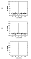
- FIG. 9 is an explanatory diagram for explaining the nature of a conventional complementary code.
- FIG (a) is an explanatory diagram showing an autocorrelation calculation result of one of the complementary code sequence a n.
- FIG (b) is an explanatory diagram showing the result of the autocorrelation calculation of the other complementary code sequence b n.
- FIG. 6C is an explanatory diagram showing the added value of the autocorrelation calculation results of two complementary code sequences (a n , b n ).
- Two complementary code sequences (a n, b n) one of the complementary code sequences a n autocorrelation calculation result of the is derived according to equation (1).
- Autocorrelation calculation result of the other complementary code sequence b n is derived according to equation (2).
- the parameter R indicates the autocorrelation calculation result.
- n> L or n ⁇ 1 the two complementary code sequences (a n , b n ) are both zero.
- the asterisk * indicates a complex conjugate operator.
- Equation (1) one of the complementary code sequences a n autocorrelation calculation result derived according to R aa (tau) is as shown in FIG. 9 (a), standing the peak when the delay time tau is zero, the delay If the time (shift time) ⁇ is not zero, there is a range side lobe.
- the autocorrelation calculation result R bb ( ⁇ ) of the other complementary code sequence b n derived according to Equation (2) has a peak when the delay time ⁇ is zero, as shown in FIG. 9B. When the delay time ⁇ is not zero, a range side lobe exists.
- the transmitting apparatus has a pulse having a width T that has undergone intra-pulse phase modulation in one of the complementary sequences and a width T that has undergone intra-pulse phase modulation in the other of the complementary sequences with a time interval w that is equal to or greater than the transmission pulse width T.
- Send a pulse Further, after receiving the reflected pulse of these two transmission pulses, the transmission device transmits two transmission pulses for each PRI (pulse repetition interval).
- the correlator of the receiving apparatus obtains a correlation between the signal at the first time interval T of the received signal at the time interval (2T + w) and the reference signal modulated by the complementary sequence used for the modulation of the first transmission pulse.
- the correlator of the receiving apparatus obtains a correlation between the signal of the last time interval T and the reference signal modulated by the other sequence of the complementary sequence.
- the received signal determiner determines a correlation value from the two correlation results obtained by the correlator.
- the reflected wave signal having a late arrival time from a target at a long distance is more attenuated than the reflected wave having a short arrival time from a target at a short distance from the measurement point.
- an AGC Auto-Gain-Control
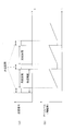
- FIG. 10 is an explanatory diagram for explaining an operation of amplifying a reflected wave signal in a conventional radar apparatus.
- FIG. 4A is an explanatory diagram showing a transmission interval of a transmission signal and a measurement interval of a reception signal.
- FIG. 5B is an explanatory diagram showing a change in gain amplified by the AGC unit within the measurement period of the received signal.
- FIG. 10A when a pulse signal is intermittently transmitted in a transmission cycle composed of a transmission interval and a non-transmission interval, a reflected wave measurement interval for the pulse signal is provided in the interval corresponding to the non-transmission interval.
- An example is shown.
- the gain of the AGC unit is increased as the elapsed time from the non-transmission section increases. Thereby, a large reception dynamic range can be realized in the radar apparatus.
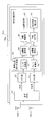
- FIG. 11 is a block diagram showing an internal configuration of a radar receiver 50a of a conventional radar apparatus.
- I signal the in-phase signal of the signal quadrature detected by the radar receiver of the radar apparatus
- Q signal the quadrature signal of the quadrature detected signal
- the AGC unit 52 amplifies the I signal output after the quadrature detection by the reception RF unit 51 with a predetermined gain.
- the AGC unit 53 amplifies the Q signal output after quadrature detection by the reception RF unit 51 with a predetermined gain.
- the I signal amplified by the AGC unit 52 is input to the A / D conversion unit 55, and the Q signal amplified by the AGC unit 53 is input to the A / D conversion unit 56.
- the I and Q signals input to the A / D conversion units 55 and 56 are signal processed by the signal processing unit 54, respectively, and the distance to the target and the arrival angle are calculated.
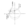
- FIG. 12 is an explanatory diagram for explaining the effect of gain variation in the AGC unit in a conventional radar apparatus.
- FIG. 12 there is a difference between the angle when the AGC units 52 and 53 operate ideally and the angle when the gains of the AGC units 52 and 53 operate with variation.
- the amplitudes of the I signal and the Q signal are different, and a phase shift amount is generated between the phase component of the I signal and the phase component of the Q signal.
- This phase shift amount becomes an error that cannot be ignored when the arrival angle estimation unit 63 of the signal processing unit 54 estimates the arrival angle of the target. Therefore, when this phase shift amount occurs, it is difficult to estimate the arrival angle of the target with high accuracy.
- the present invention has been made in view of the above-described conventional circumstances, and corrects a phase shift amount generated between the I signal and the Q signal after quadrature detection of the reflected wave signal reflected by the target in real time and appropriately.
- An object of the present invention is to provide a radar apparatus that suppresses deterioration in estimation accuracy of a target arrival angle.
- the present invention is the above-described radar apparatus, which transmits a high-frequency transmission signal from a transmission antenna at a predetermined transmission cycle, and receives a reflected wave signal reflected by a target with a reception antenna.
- a first transmission signal is generated by modulating a code obtained by concatenating the third sub code sequence and the fourth sub code sequence in the first transmission cycle, and in the second transmission cycle, the first transmission signal is generated.
- a transmission signal generation unit that generates a second transmission signal obtained by modulating a code obtained by concatenating a 5-sub code sequence and a sixth sub-code sequence, and the first and second transmission signals generated by the transmission signal generation unit Convert to transmission signal and transmit antenna And a transmission RF unit for transmitting.
- the phase shift amount generated between the I signal and the Q signal after quadrature detection of the reflected wave signal reflected by the target is corrected appropriately in real time, and the arrival angle of the target is estimated. Degradation of accuracy can be suppressed.
- segmented predetermined pulse code length 1 is a timing chart relating to the operation of the radar apparatus of the first embodiment, (a) an explanatory diagram of a transmission cycle composed of a transmission interval and a non-transmission interval, (b) an explanatory diagram of a measurement interval, and (c) a complementary code for each transmission cycle.
- Explanatory drawing explaining the relationship between the state of sequentially switching and transmitting a sequence and discrete time Timing chart regarding the operation of the AGC unit of the radar receiver, (a) an explanatory diagram for explaining how the complementary code sequence is sequentially switched for each transmission cycle, (b) an explanatory diagram of the measurement section, (c) non Explanatory drawing which showed a mode that the gain of an AGC part changes according to the elapsed time from the start timing of a transmission area.
- Explanatory drawing which shows the structure of a complex correlation value calculating part and IQ correction
- a flowchart for explaining the operations of the complex correlation value calculation unit and the IQ correction unit The block diagram which shows the other internal structure of a transmission signal generation part, (a) The block diagram which shows the internal structure of the modification of a transmission signal generation part, (b) The block which shows the internal structure of the other modification of a transmission signal generation part Figure The block diagram which shows the internal structure of the radar receiver in the modification of 1st Embodiment Explanatory drawing explaining the nature of the conventional complementary code, (a) explanatory drawing showing the autocorrelation calculation result of one complementary code sequence, (b) explanatory drawing showing the autocorrelation calculation result of the other complementary code sequence, (c) ) Explanatory drawing showing the added value of autocorrelation calculation results of two complementary code sequences
- An explanatory view for explaining an operation of amplifying a reflected wave signal in a conventional radar apparatus (a) an explanatory view showing a transmission interval of a transmission signal and a measurement interval of a reception signal, and (b) an AGC in the measurement interval
- the radar apparatus according to the following embodiment will be described using a signal including a sub code sequence pulse-modulated using a complementary code sequence as an example of a transmission signal.
- the received signal received by the radar device includes a reflected wave signal obtained by reflecting the high-frequency transmission signal from the radar device to the target and a noise signal around the radar device.
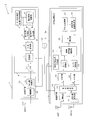
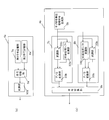
- FIG. 1 is a block diagram showing an internal configuration of the radar apparatus 1 according to the first embodiment.
- FIG. 2 is an explanatory diagram showing a procedure for generating a complementary code sequence including a sub code sequence having a sub code length obtained by dividing a predetermined pulse code length L.
- FIG. 3 is a timing chart regarding the operation of the radar apparatus 1.
- FIG. 4A is an explanatory diagram of a transmission cycle composed of a transmission interval and a non-transmission interval.
- FIG. 4B is an explanatory diagram of the measurement section.
- FIG. 6C is an explanatory diagram for explaining the relationship between the state in which complementary code sequences are sequentially switched and transmitted for each transmission period and the discrete time.
- FIG. 4 is a timing chart regarding the operation of the AGC units 19 and 20 of the radar receiver 3.
- FIG. 6A is an explanatory diagram for explaining a state in which a complementary code sequence is sequentially switched for each transmission cycle.
- FIG. 4B is an explanatory diagram of the measurement section.
- FIG. 6C is an explanatory diagram showing how the gains of the AGC units 19 and 20 change according to the elapsed time from the start timing of the non-transmission section.
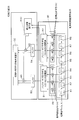
- FIG. 5 is an explanatory diagram illustrating the configuration and operation of the complex correlation value calculation unit 25 and the IQ correction unit 26.
- the radar apparatus 1 includes a local oscillator Lo, a radar transmitter 2 to which a transmission antenna ANT0 is connected, a radar receiver 3 to which a reception antenna ANT1 is connected, and a reception antenna ANT2. And a radar receiver 3a.
- the radar apparatus 1 according to the first embodiment transmits a predetermined intermittent high-frequency transmission signal generated by the radar transmitter 2 from the transmission antenna ANT0, and transmits a reflected wave signal reflected by the target to the radar receiver 3 and The signal is received by the radar receiver 3a.
- the radar apparatus 1 detects a target from the reception signals received by the radar receivers 3 and 3a.
- the target is an object to be detected by the radar apparatus 1 and is, for example, an automobile or a person, and the same applies to the following embodiments.
- the radar transmitter 2 includes a transmission signal generator 4 and a transmission RF unit 12.
- the transmission signal generation unit 4 includes a sub-code unit complementary code generation unit 5, a complex coefficient multiplication unit 6, a first code generation unit 7, a second code generation unit 8, a code switching unit 9, a modulation unit 10, , LPF (Low Pass Filter) 11.
- LPF Low Pass Filter
- the transmission signal generation unit 4 is configured to include the LPF 11, but the LPF 11 may be configured independently of the transmission signal generation unit 4.
- the transmission RF unit 12 includes a frequency conversion unit 13 and an amplifier 14.
- the transmission signal generation unit 4 Based on the reference signal generated by the local oscillator Lo, the transmission signal generation unit 4 generates a timing clock obtained by multiplying the reference signal by a predetermined multiple. Each unit of the transmission signal generation unit 4 operates based on the generated timing clock.
- the transmission signal generation unit 4 divides a complementary code sequence having a pulse code length L having L [number] elements (1) and elements ( ⁇ 1) into two, and each divided sub code sequence is divided into two.
- the baseband transmission signal r (n) is periodically generated by modulation.
- the parameter n represents a discrete time.
- the transmission signal generated by the transmission signal generation unit 4 is not a continuous signal.
- Nr [number] samples are transmitted as the baseband transmission signal r (n). Exists.
- Nu [number] samples are present as the transmission signal r (n) in the baseband.
- Tr is the transmission cycle [seconds] of the high-frequency transmission signal transmitted from the transmission antenna ANT0.
- the sub code unit complementary code generation unit 5 generates each sub code sequence (c, d) constituting the complementary code sequence (a, b) having the pulse code length L, and further, each sub code sequence (c, d) A complementary code sequence (a, b) is generated based on d).
- the code length of each sub code sequence (c, d) is represented by L / N obtained by dividing the pulse code length L of the complementary code sequence (a, b) by N.
- one complementary code sequence (a) is a concatenation of a sub code sequence (c) and a sub code sequence (d).
- the other complementary code sequence (b) is a concatenation of the sub code sequence (c) and the sub code sequence (-d).
- (a, b) each represents a complementary code sequence
- (c, d) each represents a sub-code sequence constituting the complementary code sequence.
- the parameter (p) determines the code length L of the complementary code sequence (a, b) generated by the sub code unit complementary code generation unit 5.
- the sub code unit complementary code generation unit 5 outputs the generated sub code sequence (c, d) to the complex coefficient multiplication unit 5, the first code generation unit 7, and the second code generation unit 8, respectively. .
- the complex coefficient multiplication unit 6 receives the sub code sequence (c, d) output from the sub code unit complementary code generation unit 5, and calculates the complex coefficient j for the input sub code sequence (c, d). Complex sub-code sequences (jc, jd) each multiplied are generated. The complex coefficient multiplication unit 6 outputs the generated complex sub-code sequence (jc, jd) to the first code generation unit 7 and the second code generation unit 8, respectively.
- the first code generation unit 7 outputs the sub code sequence (c, d) output from the sub code unit complementary code generation unit 5 and the complex sub code sequence (jc, jd) output from the complex coefficient multiplication unit 6. input.
- the first code generation unit 7 concatenates the sub code sequence (c) and the complex sub code sequence (jd) among the input sub code sequences and complex sub code sequences (c, d, jc, jd). As a result, a code sequence [c, jd] is generated.
- the first code generation unit 7 outputs the generated code sequence [c, jd] to the code switching unit 9.
- the code sequence generated by the first code generator 7 is referred to as “Code # 1”.
- the second code generation unit 8 uses the sub code sequence (c, d) output from the sub code unit complementary code generation unit 5 and the complex sub code sequence (jc, jd) output from the complex coefficient multiplication unit 6. input.
- the second code generation unit 8 concatenates the sub code sequence (d) and the complex sub code sequence (jc) among the input sub code sequences and complex sub code sequences (c, d, jc, jd). As a result, a code sequence [jc, d] is generated.
- the second code generation unit 8 outputs the generated code sequence [jc, d] to the code switching unit 9.
- the code sequence generated by the second code generation unit 8 is referred to as “Code # 2”.
- the code switching unit 9 receives the code sequence Code # 1 generated by the first code generation unit 7 and the code sequence Code # 2 generated by the second code generation unit 8. The code switching unit 9 sequentially switches the input code sequence Code # 1 and code sequence Code # 2 for each transmission cycle Tr and outputs the code sequence Code # 2 to the modulation unit 10 as shown in FIG. Specifically, the code switching unit 9 outputs the code sequence Code # 1 to the modulation unit 10 in the transmission period of the first transmission cycle Tr in FIG. In the transmission section of the next transmission cycle Tr, the code switching unit 9 outputs the code sequence Code # 2 to the modulation unit 10. Similarly, in the transmission section of the subsequent transmission cycle, the code switching unit 9 similarly switches the code sequence Code # 1 and the code sequence Code # 2 sequentially and outputs the same to the modulation unit 10.
- the modulation unit 10 receives the code sequence Code # 1 or the code sequence Code # 2 output from the code switching unit 9.
- the modulation unit 10 generates a transmission signal by performing pulse modulation using Nr / L samples for each code sequence on the input code sequence Code # 1 or code sequence Code # 2. Further, the modulation unit 10 generates a transmission signal by performing phase modulation as described later with reference to FIG. 6B on the input code sequence Code # 1 or code sequence Code # 2. May be. Details will be described later.
- the modulation unit 10 outputs, to the transmission RF unit 12, only the transmission signal r (n) that is equal to or less than a preset limited band among the generated transmission signals via the LPF 11.
- the transmission RF unit 12 Based on the reference signal generated by the local oscillator Lo, the transmission RF unit 12 generates a timing clock obtained by multiplying the reference signal by a predetermined multiple. The transmission RF unit 12 operates based on the generated reference signal. Specifically, the frequency conversion unit 13 receives the transmission signal r (n) generated by the transmission signal generation unit 4, performs frequency conversion on the input baseband transmission signal r (n), and performs carrier conversion. A high-frequency transmission signal in a frequency band is generated. The frequency conversion unit 13 outputs the generated high-frequency transmission signal to the amplifier 14.
- the amplifier 14 receives the output high-frequency transmission signal, amplifies the level of the input high-frequency transmission signal to a predetermined level, and outputs it to the transmission antenna ANT0.
- the amplified high-frequency transmission signal is transmitted so as to be radiated into space via the transmission antenna ANT0.
- the transmission antenna ANT0 transmits the high-frequency transmission signal output by the transmission RF unit 12 so as to be radiated into space. As shown in FIG. 3A, the high-frequency transmission signal is transmitted during the transmission interval Tw in the transmission cycle Tr, and is not transmitted during the non-transmission interval (Tr-Tw).
- the radar receiver 3 includes a reception antenna ANT1, a reception RF unit 15, an AGC unit 19, an AGC unit 20, and a signal processing unit 21.
- the radar receiving unit 3a has the same configuration as the radar receiving unit 3 except that it includes another receiving antenna ANT2 different from the receiving antenna ANT1 instead of the receiving antenna ANT1. Therefore, in the following description of the radar receivers 3 and 3a, only the radar receiver 3 will be described. However, the radar receiver 3 a performs the same operation as the radar receiver 3.
- the reception RF unit 15 includes an amplifier 16, a frequency conversion unit 17, and a quadrature detection unit 18.
- the signal processing unit 21 includes an A / D conversion unit 22, an A / D conversion unit 23, a reference transmission signal generation unit 24, a complex correlation value calculation value 25, an IQ correction unit 26, and an averaging processing unit 27.
- the arrival angle distance estimation unit 28 is provided.
- the reception antenna ANT1 receives a reflected wave signal obtained by reflecting the high-frequency transmission signal transmitted from the radar transmission unit 2 on the target and a noise signal around the radar apparatus 1 as a reception signal.
- the reflected wave signal is a high frequency band signal.
- the reception signal received by the reception antenna ANT1 is input to the reception RF unit 15.
- the radar apparatus 1 of the first embodiment is described as having two radar receivers, but the number of radar receivers is not particularly limited to two. In the radar device 1, the radar receiver holds one receiving antenna.
- the reception antenna ANT1 receives the reception signal described above in a section corresponding to the non-transmission section (Tr-Tw) in the transmission cycle Tr of the high-frequency transmission signal. Therefore, a section in which the received signal is received is a measurement section in the radar apparatus 1.
- the reception RF unit 15 generates a timing clock obtained by multiplying the reference signal by a predetermined multiple based on the reference signal generated by the local oscillator Lo.
- the reception RF unit 15 operates based on the generated timing clock.
- the amplifier 16 receives a reception signal in a high frequency band received by the reception antenna ANT1, amplifies the level of the input reception signal in the high frequency band to a predetermined level, and outputs the amplified signal to the frequency conversion unit 17. To do.
- the frequency converter 17 receives the received signal in the high frequency band output from the amplifier 16, converts the frequency of the input received signal in the high frequency band into a baseband band, and receives the frequency-converted baseband band The signal is output to the quadrature detection unit 18.
- the quadrature detection unit 18 shifts the phase components of some of the received signals of the baseband band output from the frequency conversion unit 17 by 90 degrees, thereby forming a baseband composed of the I signal and the Q signal. Generate a received signal in the band.
- the quadrature detection unit 18 outputs the generated I signal to the AGC unit 19 and outputs the generated Q signal to the AGC unit 20.
- the AGC unit 19 sets the I signal output from the quadrature detection unit 18 to the elapsed time from the start timing of the measurement section (non-transmission section) shown in FIG. Amplify with the corresponding gain.
- the gain of the AGC unit 19 is not fixed but variable as shown in FIG.
- the AGC unit 19 outputs the amplified I signal to the A / D conversion unit 22.
- the AGC unit 20 sets the Q signal output from the quadrature detection unit 18 to the elapsed time from the start timing of the measurement section (non-transmission section) shown in FIG. Amplify with the corresponding gain.
- the gain of the AGC unit 20 is not fixed but variable as shown in FIG.
- the AGC unit 20 outputs the amplified Q signal to the A / D conversion unit 23.
- the A / D conversion unit 22 converts the I signal into digital data by performing sampling at the discrete time k on the baseband I signal output from the AGC unit 19.
- the A / D conversion unit 23 converts the Q signal into digital data by performing sampling at the discrete time k on the Q signal in the baseband band output from the AGC unit 20.
- the parameter k represents a discrete time corresponding to the number of samples of the baseband transmission signal r (n) included in the high-frequency transmission signal.
- the reception signal at the discrete time k of the reception antenna ANT1 is expressed by Equation (4) using the in-phase signal I (s, k) of the reception signal and the quadrature signal Q (s, k) of the reception signal.
- the gain of the AGC unit 19 or the AGC unit 20 at the discrete time k is expressed as g (k, I) or g (k, Q).
- the discrete time k 2 (Nr + Nu) indicates the end timing of the transmission cycle Tr of the code sequence Code # 2. That is, the radar receiver 3 has a transmission cycle (2Tr) that is twice the transmission cycle Tr of the high-frequency transmission signal of the code sequence Code # 1 and the transmission cycle Tr of the high-frequency transmission signal of the code sequence Code # 2.
- the signal processing section 21 periodically calculates the signal processing section.
- K Nr at the end timing.
- the range from the transmission start timing of the high-frequency transmission signal of the code sequence Code # 1 to the transmission end timing of the high-frequency transmission signal of the code sequence Code # 2 is set repeatedly for the discrete time k.
- the reference transmission signal generator 24 multiplies the reference signal by a predetermined multiple based on the reference signal generated by the local oscillator Lo in the same manner as the transmission signal generator 4 in synchronization with the operation of the transmission signal generator 4. Generated timing clock.
- the reference transmission signal generation unit 24 periodically generates a reference transmission signal r (n) having the same baseband as the transmission signal generated by the transmission signal generation unit 4 based on the generated reference signal.
- the reference transmission signal generation unit 24 outputs the generated reference transmission signal r (n) to the complex correlation value calculation unit 25.
- the transmission signal generated by the transmission signal generation unit 4 of the radar transmission unit 2 and the reference transmission signal generated by the reference transmission signal generation unit 24 are based on an I signal Ir (k) and a Q signal Qr (k).
- the band-band signal r (n) can be expressed as Equation (5).
- the parameter g r (k) represents the gain of the AGC units 19 and 20 at the discrete time k.
- the complex correlation value calculation unit 25 includes a plurality of shift registers R1 to R8, a first sub-code unit correlation value calculation unit FR, a second sub-code unit correlation value calculation unit SR, Buffers B1 and B2.
- the IQ correction unit 26 includes buffers B3 and B4, a correction coefficient calculation unit ACC, corrected correlation value calculation units M1 and M2, and a complementary code sequence correlation value calculation unit CC.
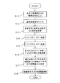
- each of the shift registers R1 to R8 inputs the complex signal x (s, k) converted by the A / D converters 22 and 23 (S11).
- Each shift register R1 to R8 inputs the complex signal x (s, k) in response to shifting the parameter m in equations (6) and (7) described later.
- the parameter m represents the shift time in the calculation of the correlation value.
- the first sub-code unit correlation value calculation unit FR and the second sub-code unit correlation value calculation unit SR each receive the reference transmission signal r (n) output by the reference transmission signal generation unit 24 (S12).
- the first sub-code unit correlation value calculation unit FR calculates the complex conjugate value of the complex signal x (s, k) input in step S11 and the reference transmission signal r (n) input in step S12. Is calculated as shown in Equation (6) (S13).
- the second sub-code unit correlation value calculation unit SR also correlates the complex value of the complex signal x (s, k) input in step S11 and the complex conjugate value of the reference transmission signal r (n) input in step S12. Is calculated as shown in Equation (7) (S13).
- the first sub-code unit correlation value calculation unit FR and the second sub-code unit correlation value calculation unit SR each perform the reference output from the reference transmission signal generation unit 24 in step S12 according to the range of the discrete time k.
- the transmission signal r (n) is switched and input.
- the reference transmission signal is input (S12).
- the reference transmission signal is input (S12).
- An asterisk (*) represents a complex conjugate operator.
- a sub code sequence correlation value between the complex signal x (s, k) and the sub code sequence of the reference transmission signal r (n) input in step S12 is calculated (S13).
- the second sub-code unit correlation value calculating unit SR receives the complex signal x (s, k) input in step S11 and the step S12 for the complex sub-code sequence having the sub code length L / N.
- a complex sub-code sequence correlation value with the complex sub-code sequence of the reference transmission signal r (n) is calculated (S13).
- a sub code sequence correlation value with the sub code sequence (c) of the transmission signal r (n) is calculated according to the equation (8) (S13).
- a complex sub-code sequence correlation value with the complex sub-code sequence (jd) of the signal r (n) is calculated according to Equation (9) (S13).
- the first sub-code unit correlation value calculation unit FR temporarily stores each sub-code sequence correlation value calculated in step S13 in the buffer B1 in the complex correlation value calculation unit 25 (S14), and the IQ correction unit 26 is output to the buffer B3 (S15). Further, the second sub-code unit correlation value calculator SR temporarily stores each complex sub-code sequence correlation value calculated in step S13 in the buffer B2 in the complex correlation value calculator 25 (S14). The data is output to the buffer B4 of the IQ correction unit 26 (S15).
- a complex sub-code sequence correlation value with the complex sub-code sequence (jc) of the transmission signal r (n) is calculated according to Equation (10) (S13).
- a sub code sequence correlation value with the sub code sequence (d) of the reference transmission signal r (n) is calculated according to the equation (11) (S13).
- the first sub-code unit correlation value calculation unit FR temporarily stores each complex sub-code sequence correlation value calculated in step S13 in the buffer B1 in the complex correlation value calculation unit 25 (S14), and performs IQ correction.
- the data is output to the buffer B3 of the unit 26 (S15).
- the second sub-code unit correlation value calculation unit SR temporarily stores each sub-code sequence correlation value calculated in step S13 in the buffer B2 in the complex correlation value calculation unit 25 (S14), and IQ
- the data is output to the buffer B4 of the correction unit 26 (S15).
- the first correction coefficient H 1 (s, k) is a complex sub code sequence correlation value AC 1 _sub 2 (s, k + (Nr / N)) when a complex sub code sequence is used for the transmission signal.
- the sub-code sequence correlation value AC 1 _sub 1 (s, k) in the case where the sub-code sequence is used for the transmission signal are calculated as coefficients when equalizing each amplitude level (amplitude scale).
- the calculated first correction coefficient H 1 (s, k) is multiplied by AC 1 _sub 2 (s, k + (Nr / N)) or AC 1 _sub 1 (s, k).
- the calculated first correction coefficient H 1 (s, k) is multiplied, and addition processing is performed as shown in Equation (13).
- the mathematical expression (12) represents the sub code sequence correlation value when the sub code sequence (c) is used for the transmission signal and the complex sub code sequence (jd) for the transmission signal. ) Indicates that the gains of the AGC units 19 and 20 are equal when the amplitude levels are the same as the complex sub-code sequence correlation value. That is, when Equation (12) is established, the gains of the AGC units 19 and 20 do not vary.
- a correction coefficient H 1 (s, k) for appropriately correcting the phase shift amount with respect to the Q signal can be calculated.
- the complex sub-code sequence correlation value AC 1 _sub 2 (s, k + (Nr / N)) is multiplied by the correction coefficient H 1 (s, k).
- the complementary code sequence correlation value calculation unit CC adds the corrected correlation value calculation result multiplied in step S17 and the sub code sequence correlation value calculated according to Equation (8) according to Equation (13) ( S18).
- the correlation value calculated according to Equation (13) represents the correlation value of the complementary code sequence of code sequence Code # 1.
- the range of the discrete time k may be further limited on the premise that the existence range of the target to be measured by the radar apparatus 1 is at a short distance from the radar apparatus 1.
- the radar apparatus 1 can reduce the calculation amount by the complex correlation value calculation unit 25 and the IQ correction unit 26. That is, the radar apparatus 1 can reduce the amount of power consumed by the signal processing unit 21.
- the second correction coefficient H 2 (s, k) is transmitted with the sub code sequence correlation value AC 2 _sub 2 (s, k + (Nr / N)) when the sub code sequence is used for the transmission signal. This is calculated as a coefficient for equalizing each amplitude level (amplitude scale) with the complex sub code sequence correlation value AC 2 _sub 1 (s, k) when a complex sub code sequence is used for the signal.
- the calculated second correction coefficient H 2 (s, k) is multiplied by AC 2 _sub 2 (s, k + (Nr / N)) or AC 2 _sub 1 (s, k).
- the mathematical formula (14) represents the complex sub code sequence correlation value when the complex sub code sequence (jc) is used for the transmission signal and the sub signal for the transmission signal.
- the amplitude levels are the same as the sub code sequence correlation value when the code sequence (d) is used, it indicates that the gains of the AGC units 19 and 20 are equal. That is, when the formula (14) is established, the gains of the AGC units 19 and 20 do not vary.
- a correction coefficient H 2 (s, k) for correct correction can be calculated.
- the sub-code sequence correlation value AC 2 —sub 2 (s, k + (Nr / N)) is multiplied by the correction coefficient H 2 (s, k).
- the complementary code sequence correlation value calculation unit CC adds the corrected correlation value calculation result multiplied in step S17 and the complex sub code sequence correlation value calculated according to equation (10) according to equation (15). (S18).
- the correlation value calculated according to Equation (15) represents the correlation value of the complementary code sequence of code sequence Code # 2.
- the range of the discrete time k may be further limited on the premise that the existence range of the target to be measured by the radar apparatus 1 is at a short distance from the radar apparatus 1.
- the radar apparatus 1 can reduce the calculation amount by the complex correlation value calculation unit 25 and the IQ correction unit 26. That is, the radar apparatus 1 can reduce the amount of power consumed by the signal processing unit 21.
- the averaging processing unit 27 calculates the correlation value of the complementary code sequence of the code sequence Code # 1 calculated according to the equation (13) and the correlation value of the complementary code sequence of the code sequence Code # 2 calculated according to the equation (15). Is added.
- the discrete time k in the calculation of the correlation value of the complementary code sequence of the code sequence Code # 2 is one period of the transmission cycle Tr compared to the discrete time k in the calculation of the correlation value of the complementary code sequence of the code sequence Code # 1. It's a minute late.
- the averaging processing unit 27 transmits the discrete time k in the calculation of the correlation value of the complementary code sequence of the code sequence Code # 2 in consideration of the difference in the discrete time k in the calculation of the correlation value of the complementary code sequence of each code sequence.
- An operation such as Expression (16) shifted in time by the period Tr is performed.
- the correlation value represented by Equation (16) is the correlation between the complementary code sequence (code sequence Code # 1, code sequence Code # 2) generated by the transmission signal generation unit 4 and the received signal received by the receiving antenna ANTs. Value.
- the radar apparatus 1 can obtain a signal in which the range side lobe is suppressed to a low level as shown in the above-described Expression (1) and FIG. 8 according to the calculation of Expression (16) by the averaging processing unit 27. .
- the arrival angle distance estimation unit 28 calculates the correlation value AC 1 (s, k) + AC 2 (s, k + Nr + Nu) of the complementary code sequences (code sequence Code # 1, code sequence Code # 2) calculated by the averaging processing unit 27.
- the target angle of arrival and the distance to the target are estimated.
- the arrival angle estimation calculation by the arrival angle distance estimation unit 25 is a known technique and can be realized by referring to, for example, the following Reference Non-Patent Document 1. Further, the estimation calculation of the distance to the target by the arrival angle distance estimation unit 28 can be realized by referring to the following non-patent document 2.
- the arrival angle distance estimation unit 28 calculates the level of the received signal at the receiving antenna based on the added correlation value of the complementary code sequence at the receiving antenna ANT1 with respect to the target arrival angle.
- the level of the received signal includes a phase component of the target arrival angle.
- the arrival angle distance estimation unit 28 estimates the angle of the phase component when the level of the reception signal takes the maximum value as the arrival angle of the target.
- the arrival angle distance estimation unit 28 based on the correlation value obtained by adding the complementary code sequence in the reception antenna ANT1 with respect to the distance to the target, the discrete time and the high frequency transmission when the correlation value takes the maximum value. Based on the time difference with the signal transmission time, the target distance is estimated.
- the amount of phase shift generated between the I signal and the Q signal after quadrature detection of the reflected wave signal reflected by the target is appropriately corrected, and the target It is possible to suppress the deterioration of the estimation accuracy of the arrival angle of.
- the radar apparatus 1 performs pulse compression on the high-frequency transmission signal with a code length L / N, a correlation value with an improved SNR (Signal Noise Ratio) in the reflected wave signal reflected by the target is obtained. Obtainable. For this reason, the radar apparatus 1 can calculate the correction coefficient for appropriately correcting the phase shift amount between the I signal and the Q signal with high accuracy, and can suppress the estimated deterioration of the arrival angle of the target. .
- low range side lobe characteristics can be maintained by using complementary code sequences (code sequence Code # 1, code sequence Code # 2). Thereby, the estimated deterioration of the arrival angle and distance of the target by the radar apparatus 1 can be suppressed.
- the radar apparatus 1 it is possible to calculate a correction coefficient corresponding to a variation in gains of the AGC units 19 and 20 that are affected by an external environment such as temperature in real time for a predetermined measurement period. it can.
- the representation of the complementary code sequence (a, b) is not limited to this representation.
- each coefficient (A, B, C, D) (1, j, j, 1) is established in the first embodiment.
- the following coefficients are used as the coefficients, the same effects as those of the first embodiment can be obtained.
- each coefficient (A, B, C, D) (j, -1, -1, j).
- each coefficient (A, B, C, D) ( ⁇ 1, ⁇ j, ⁇ j, ⁇ 1).
- ⁇ j is an inverted complex sequence.
- each coefficient (A, B, C, D) (j, 1, 1, j).
- each coefficient (A, B, C, D) ( ⁇ j, ⁇ 1, ⁇ 1, ⁇ j).
- each coefficient (A, B, C, D) ( ⁇ 1, j, j, ⁇ 1).
- the configuration of the radar apparatus 1 has a problem that a phase shift amount is generated between the I signal and the Q signal due to a variation between the gains of the AGC units 19 and 20 of the radar receiver 3.
- the problem was solved.
- the radar receiver 3 has the AGC units 19 and 20, but also when the radar receiver 3 is a direct conversion type radar apparatus that does not have the AGC units 19 and 20, after quadrature detection.
- a phase shift amount occurs between the I signal and the Q signal. That is, even in the case of the direct conversion type radar apparatus, a phase shift amount occurs between the I signal and the Q signal after the quadrature detection due to a hardware error factor of the quadrature detection unit of the reception RF unit.
- the second modification of the first embodiment includes a configuration of a direct conversion type radar apparatus that does not include the AGC units 19 and 20 in the radar receiver 3 of the first embodiment. That is, the radar apparatus according to the second modification of the first embodiment includes a radar transmission unit similar to the radar transmission unit 2 of the radar apparatus 1, omits the AGC units 19 and 20 from the radar reception unit 3 of the radar apparatus 1, Other configurations have the same configuration.
- the hardware of the quadrature detection unit of the reception RF unit A phase shift amount generated between the I signal and the Q signal generated according to the error factor can be corrected appropriately.
- the radar transmission unit of the radar apparatus generates the transmission signal shown in FIG. 7A instead of the transmission signal generation unit 4 of the radar apparatus 1 of the first embodiment.
- the configuration of the unit 4a or the transmission signal generation unit 4b shown in FIG. Note that the radar receiver in the radar device of Modification 3 of the first embodiment is the same as the radar device 1 of the first embodiment. For this reason, the description of the radar receiver in the radar apparatus according to Modification 3 of the first embodiment is omitted.
- FIG. 7 is a block diagram showing another internal configuration of the transmission signal generation unit.
- FIG. 4A is a block diagram showing an internal configuration of a transmission signal generation unit 4a that is a modification of the transmission signal generation unit 4.
- FIG. 6B is a block diagram showing an internal configuration of a transmission signal generation unit 4b which is another modification of the transmission signal generation unit 4.
- the transmission signal generation unit 4a includes a first code storage unit 7a, a second code storage unit 8a, a code switching unit 9a, and a modulation unit 10a.
- the first code storage unit 7a stores in advance the sub code sequence generated by the first code generation unit 7 in the radar apparatus 1 of the first embodiment.
- the second code storage unit 8a stores in advance the sub code sequence generated by the second code generation unit 8 in the radar apparatus 1 of the first embodiment.
- the code switching unit 9a Based on the reference signal generated by the local oscillator Lo, the code switching unit 9a generates a timing clock obtained by multiplying the reference signal by a predetermined multiple.
- the code switching unit 9a reads the stored sub code sequence from the first code storage unit 7a or the second code storage unit 8a based on the generated timing clock.
- the operation after the code switching unit 9a reads and the operation of the modulation unit 10a are the same as the operation of the code switching unit 9 and the operation of the modulation unit 10 in the transmission signal generation unit 4 of the first embodiment. Description of the contents of is omitted.
- the transmission signal generation unit 4b includes a sub-code unit complementary code generation unit 5b, a first code generation unit 7b, a second code generation unit 8b, and a code switching unit 9b.
- the first code generation unit 7b includes a modulation unit 31b, a 90-degree phase shift modulation unit 32b, and a P / S modulation unit 33b.
- the second code generation unit 8b includes a 90-degree phase shift modulation unit 34b, a modulation unit 35b, and a P / S conversion unit 36b.
- the sub code unit complementary code generation unit 5b generates a sub code sequence (c) in the same manner as the sub code unit complementary code generation unit 5 of the first embodiment, and the generated sub code sequence (c). For example, it outputs to the modulation part 31b which modulates with an I axis (in-phase axis). Further, the sub code unit complementary code generation unit 5b generates a sub code sequence (d) in the same manner as the sub code unit complementary code generation unit 5 of the first embodiment, and generates the generated sub code sequence (d). On the other hand, for example, it outputs to the 90 degree phase shift modulation part 32b which modulates with Q axis (orthogonal axis).
- the sub code unit complementary code generation unit 5b generates a sub code sequence (c) in the same manner as the sub code unit complementary code generation unit 5 of the first embodiment, and the generated sub code sequence (c). For example, the signal is output to the 90-degree phase shift modulator 34b that performs modulation on the Q axis (in-phase axis). Further, the sub code unit complementary code generation unit 5b generates a sub code sequence (d) in the same manner as the sub code unit complementary code generation unit 5 of the first embodiment, and generates the generated sub code sequence (d). On the other hand, it outputs to the modulation
- the modulation unit 31b receives the sub code sequence (c) generated by the sub code unit complementary code generation unit 5b, modulates the sub code sequence (c) with the I axis (in-phase axis), and generates the modulated signal. Is output to the P / S converter 33b.
- the 90-degree phase shift modulation unit 32b receives the sub code sequence (d) generated by the sub code unit complementary code generation unit 5b, modulates the sub code sequence (d) with the Q axis (orthogonal axis), and The modulated signal is output to the P / S converter 33b. Note that the 90-degree phase shift modulation unit 32b modulates the sub code sequence (d) on the Q axis by multiplying the complex coefficient j by the complex coefficient multiplication unit 6 of the transmission signal generation unit 4 of the first embodiment. It corresponds to being done.
- the P / S converter 33b receives the signal output from the modulator 31b and the signal output from the 90-degree phase shift modulator 32b.
- the P / S modulation unit 33b outputs the signal output from the modulation unit 31b to the code switching unit 9b, and then outputs the signal output from the 90-degree phase shift modulation unit 32b to the code switching unit 9b.
- This operation is the same as the operation of outputting the code sequence [c, jd] to the code switching unit 9 in the first code generation unit 7 of the first embodiment.
- the 90-degree phase shift modulation unit 34b receives the sub code sequence (c) generated by the sub code unit complementary code generation unit 5b, modulates the sub code sequence (c) with the Q axis (orthogonal axis), and The modulated signal is output to the P / S converter 36b. Note that the 90-degree phase shift modulation unit 34b modulates the sub code sequence (c) with the Q axis by multiplying the complex coefficient j by the complex coefficient multiplication unit 6 of the transmission signal generation unit 4 of the first embodiment. It corresponds to being done.
- the modulation unit 35b receives the sub code sequence (d) generated by the sub code unit complementary code generation unit 5b, modulates the sub code sequence (d) with the I axis (in-phase axis), and generates the modulated signal. Is output to the P / S converter 36b.
- the P / S converter 36b receives the signal output from the 90-degree phase shift modulator 34b and the signal output from the modulator 35b.
- the P / S modulation unit 36b outputs the signal output from the 90-degree phase shift modulation unit 34b to the code switching unit 9b, and then outputs the signal output from the modulation unit 35b to the code switching unit 9b.
- This operation is the same as the operation of outputting the code sequence [jc, d] to the code switching unit 9 in the first code generation unit 7 of the first embodiment.
- the code switching unit 9b includes a signal output from the first code generation unit 7b, that is, a modulated code sequence Code # 1, and a signal output from the second code generation unit 8b, that is, a modulated code sequence Code. As shown in FIG. 3C, # 2 is sequentially switched every transmission cycle Tr and output to the modulation unit 10.
- the radar apparatus of the third modification of the first embodiment it is possible to have an alternative configuration of the transmission signal generation unit 4 of the first embodiment.
- the configuration of the transmission signal generation unit 4b can be simplified.
- the IQ correction unit 26 of the signal processing unit 21 appropriately corrects the amount of phase shift between the I signal and the Q signal caused by the gain variation between the AGC units 19 and 20. It has been explained that the degradation of the estimation accuracy of the target arrival angle is suppressed.
- the amount of phase rotation accompanying the movement of the target is measured based on the correlation value shown in the mathematical expression (16) added by the averaging processing unit 27 of the first embodiment. Then, the Doppler frequency is estimated.
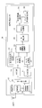
- FIG. 8 is a block diagram showing an internal configuration of the radar receiver 3b according to Modification 4 of the first embodiment.
- the radar receiver 3b includes a reception antenna ANT1, a reception RF unit 15, an AGC unit 19, an AGC unit 20, and a signal processing unit 21b.
- the signal processing unit 21b includes an A / D conversion unit 22, an A / D conversion unit 23, a reference transmission signal generation unit 24, a complex correlation value calculation unit 25, an IQ correction unit 26, and an averaging processing unit 27.
- the phase rotation amount measuring unit 29 and the Doppler frequency estimating unit 30 are provided.
- the phase rotation amount measurement unit 29 uses the correlation value of the complementary code sequence calculated by the averaging processing unit 27 as a reference correlation value, and is based on the correlation value of the complementary code sequence in each transmission period over a plurality of transmission periods NTx. Then, the phase rotation amount ⁇ (k) is measured. The phase rotation amount measurement unit 29 outputs the measured phase rotation amount ⁇ (k) to the Doppler frequency estimation unit 30.
- the Doppler frequency estimation unit 30 calculates the phase rotation amount accompanying the movement of the target, that is, the Doppler frequency f d (k), using Equation (17).
- the parameter NTx is the observation time [seconds] of the correlation value of the complementary code sequence added by the averaging processing unit 27.
- the radar apparatus of the modification 4 of 1st Embodiment based on the correlation value of the complementary code sequence calculated by the averaging process part 27, the amount of phase rotation and Doppler frequency accompanying a movement of a target are obtained. Estimation can be performed with high accuracy.
- the averaging processing unit 27 obtains a low-range sidelobe characteristic with the addition result of the correlation values in the transmission period twice the transmission period Tr of the high-frequency transmission signal as one unit. I explained that I can do it. However, the averaging processing unit 27 further calculates the addition result of the correlation values in the double transmission cycle over a plurality of transmission cycles, and calculates the addition result of the correlation values in the calculated double transmission cycle. It may be averaged. Thereby, the radar apparatus can obtain a reception signal in which the noise signal is further suppressed. That is, the calculation for estimating the arrival angle of the target and estimating the distance can be performed with high accuracy.
- the A / D converters 22 and 23 perform oversampling according to the discrete time k on the baseband I signal and Q signal amplified by the AGC units 19 and 20. Convert to digital data.
- the radar receivers 3 and 3a do not need to perform A / D conversion at the same sampling rate as the baseband transmission signal in the radar transmitter 2.
- a baseband transmission signal is generated using the number of samples of Nr with respect to the code length L. This corresponds to oversampling of Nr / L samples per code.
- the radar receivers 3 and 3a can process the received signal as long as the number of samples is one or more times per code.
- the radar apparatus appropriately corrects the phase shift amount generated between the I signal and the Q signal after quadrature detection of the signal reflected by the target, and suppresses the deterioration of the estimation accuracy of the target arrival angle. It is useful as a radar device.
Landscapes
- Engineering & Computer Science (AREA)
- Radar, Positioning & Navigation (AREA)
- Remote Sensing (AREA)
- Computer Networks & Wireless Communication (AREA)
- Physics & Mathematics (AREA)
- General Physics & Mathematics (AREA)
- Radar Systems Or Details Thereof (AREA)
Priority Applications (3)
| Application Number | Priority Date | Filing Date | Title |
|---|---|---|---|
| CN201180034765.1A CN103003714B (zh) | 2010-07-29 | 2011-07-14 | 雷达装置 |
| US13/811,641 US9134405B2 (en) | 2010-07-29 | 2011-07-14 | Radar apparatus |
| EP11812004.7A EP2600170A4 (en) | 2010-07-29 | 2011-07-14 | RADAR DEVICE |
Applications Claiming Priority (2)
| Application Number | Priority Date | Filing Date | Title |
|---|---|---|---|
| JP2010-170821 | 2010-07-29 | ||
| JP2010170821A JP5810287B2 (ja) | 2010-07-29 | 2010-07-29 | レーダ装置 |
Publications (1)
| Publication Number | Publication Date |
|---|---|
| WO2012014402A1 true WO2012014402A1 (ja) | 2012-02-02 |
Family
ID=45529636
Family Applications (1)
| Application Number | Title | Priority Date | Filing Date |
|---|---|---|---|
| PCT/JP2011/004028 Ceased WO2012014402A1 (ja) | 2010-07-29 | 2011-07-14 | レーダ装置 |
Country Status (5)
| Country | Link |
|---|---|
| US (1) | US9134405B2 (enExample) |
| EP (1) | EP2600170A4 (enExample) |
| JP (1) | JP5810287B2 (enExample) |
| CN (1) | CN103003714B (enExample) |
| WO (1) | WO2012014402A1 (enExample) |
Cited By (1)
| Publication number | Priority date | Publication date | Assignee | Title |
|---|---|---|---|---|
| US11187781B2 (en) * | 2016-12-22 | 2021-11-30 | Furukawa Electric Co., Ltd. | Pulse generating device and output adjustment method thereof |
Families Citing this family (18)
| Publication number | Priority date | Publication date | Assignee | Title |
|---|---|---|---|---|
| JP5861059B2 (ja) * | 2010-09-01 | 2016-02-16 | パナソニックIpマネジメント株式会社 | レーダ装置 |
| JP5842143B2 (ja) * | 2010-09-02 | 2016-01-13 | パナソニックIpマネジメント株式会社 | レーダ装置 |
| JP6116126B2 (ja) * | 2012-03-29 | 2017-04-19 | パナソニック株式会社 | レーダ装置 |
| KR101397548B1 (ko) | 2012-03-29 | 2014-05-27 | 연세대학교 산학협력단 | 위치측정 장치 및 방법 |
| JP5986835B2 (ja) * | 2012-07-19 | 2016-09-06 | パナソニック株式会社 | センシング方法及びセンシング装置 |
| AU2013328486B2 (en) * | 2012-10-08 | 2017-11-09 | Mbda Uk Limited | Improvements in and relating to radar receivers |
| US9405003B2 (en) | 2013-02-26 | 2016-08-02 | Panasonic Corporation | Radar apparatus |
| CN103364784A (zh) * | 2013-07-22 | 2013-10-23 | 武汉大学 | 一种环视合成孔径成像雷达 |
| JP6375250B2 (ja) * | 2015-03-03 | 2018-08-15 | パナソニック株式会社 | レーダ装置 |
| KR101644066B1 (ko) * | 2015-12-15 | 2016-07-29 | 주식회사 바이다 | 다중빔 생성 레이더 장치 |
| JP6678485B2 (ja) * | 2016-03-16 | 2020-04-08 | パナソニック株式会社 | レーダ装置及びレーダ方法 |
| JP2018054494A (ja) * | 2016-09-29 | 2018-04-05 | パナソニックIpマネジメント株式会社 | 検知装置、検知方法および検知プログラム |
| US10912493B2 (en) * | 2017-01-06 | 2021-02-09 | Panasonic Intellectual Property Management Co., Ltd. | Sensor and method |
| JP6917735B2 (ja) * | 2017-03-07 | 2021-08-11 | パナソニック株式会社 | レーダ装置及びレーダ方法 |
| CN107247268B (zh) * | 2017-05-16 | 2020-01-21 | 深圳市速腾聚创科技有限公司 | 多线激光雷达系统及其水平安装角度的校正方法 |
| CN110703234B (zh) * | 2019-10-29 | 2021-07-02 | 杭州瑞利海洋装备有限公司 | 一种三维摄像声纳阵列信号接收机幅相校正装置及方法 |
| JPWO2023026548A1 (enExample) * | 2021-08-23 | 2023-03-02 | ||
| EP4555341A1 (en) * | 2022-07-15 | 2025-05-21 | Focal Point Positioning Limited | Method and apparatus that uses a transmission from a single transmitter for receiver positioning |
Citations (5)
| Publication number | Priority date | Publication date | Assignee | Title |
|---|---|---|---|---|
| JPS6196482A (ja) * | 1984-10-17 | 1986-05-15 | Toshiba Corp | レ−ダシステム |
| JPH02196982A (ja) * | 1989-01-26 | 1990-08-03 | Mitsubishi Electric Corp | 位相変調パルス相関器 |
| US5786788A (en) * | 1996-10-08 | 1998-07-28 | Raytheon Company | Radar system and method for reducing range sidelobes |
| JPH10268040A (ja) | 1997-03-26 | 1998-10-09 | Mitsubishi Electric Corp | パルス圧縮送受信装置及びパルス圧縮送受信方法 |
| JP2010170821A (ja) | 2009-01-22 | 2010-08-05 | Hirose Electric Co Ltd | 平型導体用電気コネクタ |
Family Cites Families (13)
| Publication number | Priority date | Publication date | Assignee | Title |
|---|---|---|---|---|
| US4153900A (en) * | 1967-12-20 | 1979-05-08 | Rockwell International Corporation | Phase-coded pulse compression type pulsed energy system |
| JPH01303135A (ja) | 1988-05-31 | 1989-12-07 | Yokogawa Medical Syst Ltd | 分散圧縮方式パルスエコーシステム送受信装置 |
| US6373859B1 (en) * | 1996-09-10 | 2002-04-16 | Hewlett-Packard Company | Methods and apparatus for encoding and decoding data |
| ES2164613B1 (es) | 2000-08-16 | 2003-05-16 | Fuente Vicente Diaz | Metodo, transmisor y receptor para comunicacion digital de espectro ensanchado mediante modulacion de secuencias complementarias golay. |
| JP3404022B2 (ja) | 2001-01-18 | 2003-05-06 | 三菱電機株式会社 | レーダのパルス圧縮装置 |
| US6930631B2 (en) * | 2001-11-28 | 2005-08-16 | M/A-Com, Inc. | Sensor front-end with phase coding capability |
| US7099367B2 (en) * | 2002-06-14 | 2006-08-29 | Time Domain Corporation | Method and apparatus for converting RF signals to baseband |
| JP2006173756A (ja) | 2004-12-13 | 2006-06-29 | Naoki Suehiro | 通信方法及び受信機 |
| CN1767420A (zh) | 2005-09-06 | 2006-05-03 | 浙江大学 | 一种广义成对互补码的产生方法 |
| DE102007041669B4 (de) * | 2007-09-01 | 2013-04-18 | Eads Deutschland Gmbh | Verfahren zur Verbesserung der Signalqualität von Radaranlagen |
| JP2009069022A (ja) * | 2007-09-13 | 2009-04-02 | Panasonic Corp | レーダ装置、その制御方法及び車両 |
| US20090092392A1 (en) | 2007-10-08 | 2009-04-09 | Nec Laboratories America, Inc. | Virtual i/q multiplexing in optical code division for secure local area ofdm |
| US8570150B1 (en) * | 2009-01-07 | 2013-10-29 | Doug Bowen | Sensing system and method with integral sensor locating capability |
-
2010
- 2010-07-29 JP JP2010170821A patent/JP5810287B2/ja not_active Expired - Fee Related
-
2011
- 2011-07-14 US US13/811,641 patent/US9134405B2/en not_active Expired - Fee Related
- 2011-07-14 EP EP11812004.7A patent/EP2600170A4/en not_active Withdrawn
- 2011-07-14 CN CN201180034765.1A patent/CN103003714B/zh not_active Expired - Fee Related
- 2011-07-14 WO PCT/JP2011/004028 patent/WO2012014402A1/ja not_active Ceased
Patent Citations (5)
| Publication number | Priority date | Publication date | Assignee | Title |
|---|---|---|---|---|
| JPS6196482A (ja) * | 1984-10-17 | 1986-05-15 | Toshiba Corp | レ−ダシステム |
| JPH02196982A (ja) * | 1989-01-26 | 1990-08-03 | Mitsubishi Electric Corp | 位相変調パルス相関器 |
| US5786788A (en) * | 1996-10-08 | 1998-07-28 | Raytheon Company | Radar system and method for reducing range sidelobes |
| JPH10268040A (ja) | 1997-03-26 | 1998-10-09 | Mitsubishi Electric Corp | パルス圧縮送受信装置及びパルス圧縮送受信方法 |
| JP2010170821A (ja) | 2009-01-22 | 2010-08-05 | Hirose Electric Co Ltd | 平型導体用電気コネクタ |
Non-Patent Citations (3)
| Title |
|---|
| J. J. BUSSGANG ET AL.: "A Unified Analysis of Range Performance of CW, Pulse, and Pulse Dopper Radar", PROCEEDINGS OF THE IRE, vol. 47, no. 10, 1959, pages 1753 - 1762, XP011156457 |
| JAMES A. CADZOW: "Direction of Arrival Estimation Using Signal Subspace Modeling", IEEE, vol. 28, 1992, pages 64 - 79 |
| See also references of EP2600170A4 |
Cited By (1)
| Publication number | Priority date | Publication date | Assignee | Title |
|---|---|---|---|---|
| US11187781B2 (en) * | 2016-12-22 | 2021-11-30 | Furukawa Electric Co., Ltd. | Pulse generating device and output adjustment method thereof |
Also Published As
| Publication number | Publication date |
|---|---|
| CN103003714B (zh) | 2016-06-01 |
| US20130120185A1 (en) | 2013-05-16 |
| US9134405B2 (en) | 2015-09-15 |
| JP2012032229A (ja) | 2012-02-16 |
| CN103003714A (zh) | 2013-03-27 |
| EP2600170A4 (en) | 2015-07-15 |
| JP5810287B2 (ja) | 2015-11-11 |
| EP2600170A1 (en) | 2013-06-05 |
Similar Documents
| Publication | Publication Date | Title |
|---|---|---|
| JP5810287B2 (ja) | レーダ装置 | |
| JP6105473B2 (ja) | レーダ装置 | |
| JP5938737B2 (ja) | レーダ装置 | |
| US9097791B2 (en) | Radar device | |
| JP6818541B2 (ja) | レーダ装置および測位方法 | |
| JP6148622B2 (ja) | レーダ装置 | |
| JP5535024B2 (ja) | レーダ装置 | |
| JP5842143B2 (ja) | レーダ装置 | |
| US9234956B2 (en) | Radar device | |
| JP6092785B2 (ja) | レーダ装置 | |
| JP2018151313A (ja) | レーダ装置及びレーダ方法 | |
| JP2014081311A (ja) | レーダ装置 | |
| CN105938192B (zh) | 雷达装置 |
Legal Events
| Date | Code | Title | Description |
|---|---|---|---|
| 121 | Ep: the epo has been informed by wipo that ep was designated in this application |
Ref document number: 11812004 Country of ref document: EP Kind code of ref document: A1 |
|
| WWE | Wipo information: entry into national phase |
Ref document number: 13811641 Country of ref document: US |
|
| WWE | Wipo information: entry into national phase |
Ref document number: 2011812004 Country of ref document: EP |
|
| NENP | Non-entry into the national phase |
Ref country code: DE |