WO2012011353A1 - 電子血圧計 - Google Patents
電子血圧計 Download PDFInfo
- Publication number
- WO2012011353A1 WO2012011353A1 PCT/JP2011/064286 JP2011064286W WO2012011353A1 WO 2012011353 A1 WO2012011353 A1 WO 2012011353A1 JP 2011064286 W JP2011064286 W JP 2011064286W WO 2012011353 A1 WO2012011353 A1 WO 2012011353A1
- Authority
- WO
- WIPO (PCT)
- Prior art keywords
- internal pressure
- fluid bag
- air bag
- blood pressure
- control
- Prior art date
- Legal status (The legal status is an assumption and is not a legal conclusion. Google has not performed a legal analysis and makes no representation as to the accuracy of the status listed.)
- Ceased
Links
Images





Classifications
-
- A—HUMAN NECESSITIES
- A61—MEDICAL OR VETERINARY SCIENCE; HYGIENE
- A61B—DIAGNOSIS; SURGERY; IDENTIFICATION
- A61B5/00—Measuring for diagnostic purposes; Identification of persons
- A61B5/02—Detecting, measuring or recording for evaluating the cardiovascular system, e.g. pulse, heart rate, blood pressure or blood flow
- A61B5/021—Measuring pressure in heart or blood vessels
- A61B5/022—Measuring pressure in heart or blood vessels by applying pressure to close blood vessels, e.g. against the skin; Ophthalmodynamometers
- A61B5/0225—Measuring pressure in heart or blood vessels by applying pressure to close blood vessels, e.g. against the skin; Ophthalmodynamometers the pressure being controlled by electric signals, e.g. derived from Korotkoff sounds
-
- A—HUMAN NECESSITIES
- A61—MEDICAL OR VETERINARY SCIENCE; HYGIENE
- A61B—DIAGNOSIS; SURGERY; IDENTIFICATION
- A61B5/00—Measuring for diagnostic purposes; Identification of persons
- A61B5/02—Detecting, measuring or recording for evaluating the cardiovascular system, e.g. pulse, heart rate, blood pressure or blood flow
- A61B5/021—Measuring pressure in heart or blood vessels
- A61B5/022—Measuring pressure in heart or blood vessels by applying pressure to close blood vessels, e.g. against the skin; Ophthalmodynamometers
- A61B5/02233—Occluders specially adapted therefor
-
- A—HUMAN NECESSITIES
- A61—MEDICAL OR VETERINARY SCIENCE; HYGIENE
- A61B—DIAGNOSIS; SURGERY; IDENTIFICATION
- A61B5/00—Measuring for diagnostic purposes; Identification of persons
- A61B5/02—Detecting, measuring or recording for evaluating the cardiovascular system, e.g. pulse, heart rate, blood pressure or blood flow
- A61B5/021—Measuring pressure in heart or blood vessels
- A61B5/022—Measuring pressure in heart or blood vessels by applying pressure to close blood vessels, e.g. against the skin; Ophthalmodynamometers
- A61B5/0235—Valves specially adapted therefor
-
- A—HUMAN NECESSITIES
- A61—MEDICAL OR VETERINARY SCIENCE; HYGIENE
- A61B—DIAGNOSIS; SURGERY; IDENTIFICATION
- A61B5/00—Measuring for diagnostic purposes; Identification of persons
- A61B5/68—Arrangements of detecting, measuring or recording means, e.g. sensors, in relation to patient
- A61B5/6801—Arrangements of detecting, measuring or recording means, e.g. sensors, in relation to patient specially adapted to be attached to or worn on the body surface
- A61B5/6813—Specially adapted to be attached to a specific body part
- A61B5/6824—Arm or wrist
Definitions
- the present invention relates to an electronic sphygmomanometer, and more particularly to an electronic sphygmomanometer that automatically wraps a measurement band (cuff) containing an air bag around a measurement site.
- a measurement band cuff
- Blood pressure is one of the indices for analyzing cardiovascular diseases, and risk analysis based on blood pressure is effective in preventing cardiovascular diseases such as stroke, heart failure and myocardial infarction.
- diagnosis has been performed based on blood pressure (anytime blood pressure) measured at a medical institution such as when visiting a hospital or during a medical examination.
- blood pressure measured at home home blood pressure
- blood pressure monitors used at home have become widespread.
- ⁇ ⁇ Many home-use sphygmomanometers employ blood pressure measurement methods based on the oscillometric method or microphone method.
- a measurement band (cuff) containing an air bag is wrapped around a measurement site such as the upper arm, and the internal pressure (cuff pressure) of the cuff is increased by a predetermined pressure (for example, 30 mmHg) higher than the systolic blood pressure.
- a predetermined pressure for example, 30 mmHg
- the arterial volume change in the process of gradually or gradually reducing the cuff pressure is detected as a pressure change (pressure pulse wave amplitude) superimposed on the cuff pressure, and the systolic phase is determined from the change in the pressure pulse wave amplitude.
- a method for determining blood pressure and diastolic blood pressure In the oscillometric method, it is also possible to measure the blood pressure by detecting the pressure pulse wave amplitude generated during the pressurization of the cuff pressure.
- a cuff is wound around a measurement site such as the upper arm, and the cuff pressure is increased by a predetermined pressure above the systolic blood pressure, as in the oscillometric method.
- Korotkoff sound generated from the artery in the process of gradually reducing the cuff pressure is detected by a microphone provided in the cuff, and the cuff pressure at which the Korotkoff sound is generated is determined as systolic blood pressure, cuff with Korotkoff sound attenuated or disappeared.
- This is a method for determining the pressure as a diastolic blood pressure.
- Patent Document 2 Japanese Patent Application Laid-Open No. 2009-279196
- the cuff structure in the fully automatic arm sphygmomanometer compresses the artery at the measurement site for blood pressure measurement, and air volume changes in the artery that occur during the process of gradually increasing or decreasing the pressure. It has a double structure of a measurement air bag for calculating the blood pressure from the pressure change in the bag and a winding mechanism for winding the measurement air bag around the measurement unit. A flexible member (hereinafter, curler) is provided between these two configurations.
- a fully automatic arm sphygmomanometer air flows into the wrapping air bag, pressurizes it, winds the measurement air bag around the measurement site via the curler, and then pressurizes and depressurizes the measurement air bag to detect the pressure pulse wave amplitude.
- the systolic blood pressure and the diastolic blood pressure are determined from the change in the pressure pulse wave amplitude.
- the present invention has been made in view of such problems, and particularly in an electronic sphygmomanometer that automatically wraps a measurement band (cuff) containing an air bag around a measurement site, the cuff is appropriately wound around the measurement site. It is an object of the present invention to provide an electronic sphygmomanometer that controls the measurement air bag pressure and the pressure of the winding mechanism.
- an electronic sphygmomanometer includes a first fluid bag and a first adjustment for injecting / discharging fluid into the first fluid bag at a variable flow rate.
- a device a sensor for detecting the internal pressure of the first fluid bag, a winding device for winding the first fluid bag around the measurement site of the subject with variable winding strength, and for adjusting the winding strength of the winding device
- a second adjusting device and a control device are examples of the winding device.
- the control device outputs a first control signal to the first adjustment device so that a change rate of the internal pressure and / or the fluid amount of the first fluid bag becomes a predetermined change rate;
- the second control signal is output to the second adjustment device so that the winding strength becomes a predetermined ratio with the change rate of the internal pressure and / or the fluid amount of the first fluid bag under the first control process. 2 and a calculation process for calculating the blood pressure value of the subject based on the change in the internal pressure of the first fluid bag detected under the first control process.
- the first control signal is set in advance so that the rate of change of the internal pressure of the first fluid bag and the rate of change of the amount of fluid in the first fluid bag are proportional to each other.
- the signal is set in advance according to the first control signal so as to have the predetermined ratio, and the control device performs feedforward control on the first control process and the second control process.
- the winding device is a second fluid bag positioned on the side farther from the measurement site than the first fluid bag at the time of mounting, and the second adjustment device has a variable flow rate of fluid in the second fluid bag.
- the second control process includes a process for determining a drive voltage for the pump and / or the valve.
- control device includes the circumference of the measurement site, the blood pressure value of the subject already measured, the blood pressure value of the subject estimated at the time of pressurization, the size of the first fluid bag, and the first fluid bag.
- the predetermined ratio is determined as a preset ratio according to at least one of the maximum values of pressure, or is changed by a preset correction formula.
- control device determines the perimeter of the measurement site and / or the size of the first fluid bag based on the rate of change of the internal pressure when the first fluid bag is pressurized.
- control device determines the blood pressure value of the subject by acquiring the previous measurement result.
- the calculation process calculates a blood pressure value based on a change in the internal pressure of the first fluid bag when the first fluid bag is depressurized under the first control process, and the control device includes the first fluid bag.
- the blood pressure value calculated based on the change in the internal pressure of the first fluid bag at the time of pressurizing the bag is set as the blood pressure value of the subject used to determine the predetermined ratio.
- the electronic sphygmomanometer is at least one of the perimeter of the measurement site, the blood pressure value of the subject already measured, the size of the first fluid bag, and the maximum value of the pressure in the first fluid bag.
- An input device for receiving two inputs is further provided.
- the electronic sphygmomanometer is at least one of the perimeter of the measurement site, the blood pressure value of the subject already measured, the size of the first fluid bag, and the maximum value of the pressure in the first fluid bag. Is further provided with a reading device for reading from the other device.
- the control device includes at least one of a time point when the internal pressure of the first fluid bag reaches a predetermined level, a time point when the winding strength reaches a predetermined level, and a time point when a predetermined time has elapsed from the predetermined time point of the measurement process.
- the predetermined ratio is changed to a preset ratio, or is changed by a preset correction formula.
- control device changes the predetermined ratio to a preset ratio according to the magnitude of the pulse wave amplitude detected from the internal pressure of the first fluid bag, or changes by a preset correction formula. .
- a control method includes: a first fluid bag; a first adjusting device for injecting / extracting fluid into the first fluid bag at a variable flow rate; and a first fluid bag.
- a control method for an electronic sphygmomanometer comprising: a sensor for detecting the internal pressure of the first blood bag; and a winding device for winding the first fluid bag around the measurement site of the subject with a variable winding strength.
- the first fluid under the control of the first adjusting device so that the rate of change of the internal pressure and / or the amount of fluid becomes a predetermined rate of change, and the step of controlling the first adjusting device with the winding strength.
- the first fluid bag detected under the control of the step of controlling the second adjustment device so as to be a predetermined ratio with the rate of change of the internal pressure and / or the fluid amount of the bag, and the step of controlling the first adjustment device The blood pressure value of the subject is calculated based on the internal pressure change And a step of.
- the cuff is appropriately wound around the measurement site at the time of measurement, and the measurement accuracy can be improved.
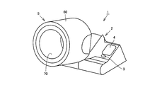
- FIG. 1 is a perspective view showing a specific example of the appearance of a blood pressure measurement device (hereinafter referred to as a sphygmomanometer) 1 according to the first embodiment.
- a sphygmomanometer a blood pressure measurement device
- a sphygmomanometer 1 mainly includes a main body 2 placed on a desk or the like, and a measurement unit 5 for inserting an upper arm as a measurement site.
- An upper part of the main body 2 includes an operation unit 3 on which a power switch, a measurement switch, a stop switch, a user selection switch, and the like are arranged, a display unit 4, and an elbow rest.
- the measuring unit 5 is attached to the main body 2 at a variable angle, and includes a housing 60 that is a substantially cylindrical machine frame, and a living body compression fixing device that is housed in the inner peripheral portion of the housing 60. As shown in FIG. 1, the living body pressing and fixing device housed in the inner peripheral portion of the housing 60 is not exposed and is covered with a cover 70 in a normal use state.
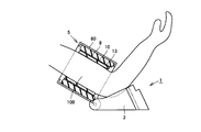
- FIG. 2 is a schematic cross-sectional view of the sphygmomanometer 1 during blood pressure measurement.
- upper arm 100 is inserted into housing 60 and the elbow is placed on the elbow rest to instruct the start of measurement.
- the upper arm 100 is compressed and fixed by the living body compression fixing device, and the blood pressure is measured.
- the living body pressure fixing device corresponds to a cuff and is an air bag 13 which is a measurement fluid bag for measuring blood pressure by compressing a measurement site, and is positioned outside the air bag 13 and substantially expandable and contractable in the radial direction.
- the curler 10 is a cylindrical flexible member, and is located outside the curler 10 and expands to press the outer peripheral surface of the curler 10 inward to reduce the diameter of the curler 10.
- an air bag 8 which is a fluid bag for pressing and fixing the air bag 13 to the measurement site of the living body.
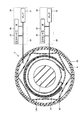
- FIG. 3 is a cross-sectional view for explaining the internal structure of the measurement unit 5.
- air bag 8 is provided inside housing 60, and is inflated / reduced by air system 30 (see FIG. 4) for compression and fixation described later.
- a curler 10 made of a plate-like member wound in a substantially cylindrical shape is disposed inside the air bag 8 (measurement site side), and elastically deforms in the radial direction when an external force is applied.
- the air bag 13 is disposed inside the curler 10 and is inflated / reduced by a measurement air system 20 (see FIG. 4) described later.
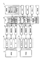
- FIG. 4 is a block diagram illustrating a specific example of a functional configuration of the sphygmomanometer 1.
- sphygmomanometer 1 includes air bag 13 and air bag 8, and is connected to air system 20 for measurement and air system 30 for compression and fixing, respectively.
- the air system 20 includes a pressure sensor 23 for measuring the internal pressure of the air bag 13, a pump 21 for supplying / exhausting air to the air bag 13, and a valve 22.
- the air system 30 includes the air bag 8.
- a pressure sensor 33 for measuring the internal pressure, a pump 31 for supplying / exhausting air to / from the air bag 8, and a valve 32 are included.
- the air bag 13 is connected to a pressure sensor 23 for measuring a change in internal pressure of the air bag 13, a pump 21 for injecting / exhausting air to the air bag 13, and a valve 22.
- the air bag 8 is connected to a pressure sensor 33 for measuring a change in internal pressure of the air bag 8, a pump 31 for injecting / exhausting air to the air bag 8, and a valve 32.
- Pressure sensors 23 and 33, pumps 21 and 31, and valves 22 and 32 are connected to oscillation circuits 28 and 38, drive circuits 26 and 36, and drive circuits 27 and 37, respectively.
- the drive circuits 26 and 36 and the drive circuits 27 and 37 are all connected to a CPU (Central Processing Unit) 40 for controlling the sphygmomanometer 1 as a whole.
- CPU Central Processing Unit
- the CPU 40 further includes a display unit 4, an operation unit 3, a memory 6 that stores a program executed by the CPU 40 and serves as a work area when executing the program, and a memory 7 that stores measurement results and the like. Then, an external interface (I / F) 80 for connecting to an external device and inputting / outputting data is connected.
- I / F external interface
- the CPU 40 outputs a control signal to the drive circuits 26 and 27 to control the pump 21 and the valve 22, and outputs a control signal to the drive circuits 36 and 37 to control the pump 31 and the valve 32.
- the drive circuits 26 and 36 drive the pumps 21 and 31, respectively, according to control signals from the CPU 40. As a result, air is injected into the air bags 13 and 8.
- the drive circuits 27 and 37 drive the valves 22 and 32, respectively, according to the control signal from the CPU 40. As a result, the valves 22 and 32 are opened / closed. Further, the opening width (hereinafter referred to as a gap) is controlled, and the discharge amount and discharge speed of the air in the air bags 13 and 8 are controlled.
- the pressure sensors 23 and 33 are capacitance type pressure sensors, and their capacitance values change due to changes in the internal pressure of the air bags 13 and 8, respectively.
- the pressure sensors 23 and 33 are connected to the oscillation circuits 28 and 38, respectively.
- the oscillation circuits 28 and 38 convert the signals into oscillation signals corresponding to the capacitance values of the pressure sensors 23 and 33, and input the signals to the CPU 40.
- the first control unit 41 and the second control unit 42 of the CPU 40 output control signals to the drive circuits 26 and 27 and the drive circuits 36 and 37 to control the pumps 21 and 31 and the valves 22 and 32. Further, the calculation unit 43 of the CPU 40 calculates a blood pressure value based on the change in the internal pressure of the air bladder 13 obtained from the pressure sensor 23.
- the display control unit 44 of the CPU 40 performs processing for displaying the measurement result on the display unit 4, and outputs data and control signals for display to the display unit 4. Further, the CPU 40 performs a process for storing the blood pressure value in the memory 7.
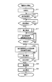
- FIG. 5 is a flowchart showing the blood pressure measurement operation of the sphygmomanometer 1 according to the first embodiment.
- the blood pressure measurement operation shown in the flowchart of FIG. 5 is an operation in the case where the CPU 40 calculates a blood pressure value based on an internal pressure change in the process of reducing the pressure of the air bladder 13. This operation is started when the CPU 40 receives an operation signal when the power switch of the operation unit 3 is pressed, and the CPU 40 reads and executes a program stored in the memory 6 to execute each unit shown in FIG. It is realized by controlling.
- step S11 the user selection switch and the measurement switch are waited for.
- step S17 when the CPU 40 receives an operation signal when the user selection switch is pressed and then an operation signal when the measurement switch is pressed (YES in step S13 and YES in step S15), in step S17.
- CPU40 starts the winding operation
- the CPU 40 preliminarily pressurizes the air bag 13 by supplying a predetermined amount of air, and then pressurizes the air bag 8 until the internal pressure of the air bag 13 and the change in the internal pressure reach a predetermined value.
- the measurement air bag 13 is automatically properly wound around the upper arm, which is the measurement site of the user.
- the CPU 40 executes a pressurizing operation for pressurizing the internal pressure of the measurement air bladder 13 until it reaches a predetermined internal pressure in step S19. Meanwhile, the CPU 40 monitors the internal pressure of the air bladder 13 obtained from the pressure sensor 23, and determines whether or not the predetermined pressure is set in advance.
- the predetermined pressure here may be a pressure that is high enough to close the blood vessel. Or when the measurement result of the selected user is memorize
- the CPU 40 executes a pressure reducing operation for starting the pressure reduction of the air bags 13, 8 in step S23.
- the decompression operation is continued until blood pressure calculation (S25) described later is completed.
- step S25 the CPU 40 calculates a blood pressure value based on the change in the internal pressure of the air bladder 13 during the pressure reducing operation of the air bladder 13 in step S23.
- the CPU 40 ends the pressure reducing operation in step S23, and in step S29, the internal pressure of the air bags 13 and 8 is rapidly reduced. Release the pressure of the living body.
- CPU40 performs the operation
- the first control unit 41 of the CPU 40 includes a drive voltage determining unit 412 for determining a voltage for driving the pump 21 and the valve 22 (hereinafter referred to as drive voltage E1). .
- the drive voltage determination unit 412 acquires the internal pressure of the air bladder 13 and the internal pressure change, and determines the drive voltage E1 as the rate of change of the internal pressure such that these values become predetermined values. Then, a control signal for driving the pump 21 and / or the valve 22 with the determined drive voltage E1 is generated, and the control signal is output to the drive circuit 26 and / or the drive circuit 27.
- Feedforward control Alternatively, the first control unit 41 of the CPU 40 outputs a preset control signal to control the internal pressure and the change in the internal pressure of the air bladder 13 in the pressure reducing operation in step S23. Feed forward control may be performed. The case of performing this feedforward control will be described in detail.
- the first control unit 41 of the CPU 40 includes a circumference information acquisition unit 411 for obtaining circumference information that is information indicating the circumference of the measurement site of the user, And a drive voltage determination unit 412 for determining a drive voltage E1 for driving the drive circuit 22.
- circumference information acquisition unit 411 receives a rotation signal from the operation signal from the operation unit 3. Get length information.
- the circumference information may be acquired by input from the external I / F 80.
- the internal pressure control for acquiring the circumference information may be performed in the CPU 40, and the circumference information acquisition unit 411 may acquire the circumference information according to the result. Specifically, after receiving the user's selection in the measurement operation, the CPU 40 outputs a control signal for driving the pump 21 at a predetermined voltage specified in advance to the drive circuit 26, and at the predetermined voltage. The pump 21 is driven to pressurize the air bladder 13 until the air bladder 13 reaches a predetermined pressure. The CPU 40 measures the time required to reach a predetermined pressure. The circumference information acquisition unit 411 stores in advance the correspondence between the time required to reach a predetermined pressure and the circumference, and obtains the circumference information of the user based on the correspondence. it can.
- the circumference information acquisition unit 411 acquires the circumference based on the time required for pressurization by storing in advance such correspondence relationship that the circumference increases as the time required for pressurization increases. be able to. In addition, it replaces with pressurization time and is obtained similarly from the rotation speed of the pump 21 and the pressure of the air bag 13.
- a cloth (not shown) as a mechanism for winding the air bag 13 around the measurement site includes a slide resistance, and the circumference information acquisition unit 411 winds the air bag 13 around the measurement site.
- the circumference information may be acquired from the resistance value obtained from the above slide resistance.
- the drive voltage determination unit 412 determines the drive voltage E1 based on the acquired circumference information. Hereinafter, determination of the drive voltage E1 in the drive voltage determination unit 412 will be described.
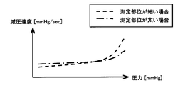
- the degree of change in the decompression speed with respect to the pressure of the air bag when the driving voltage E1 is kept constant varies depending on the circumference of the measurement site.
- the circumference of the measurement site is a parameter for determining the drive voltage E1.
- the drive voltage determination unit 412 determines the drive voltage E1 using the relationship shown in FIG.
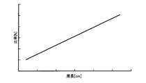
- FIG. 7 is a diagram showing the relationship between the drive voltage E1 and the circumference calculated using the relational expression (1) between the circumference information and the drive voltage E1.
- the drive voltage determination unit 412 uses the above-described equation (1) to determine the drive voltage E1 having a magnitude proportional to the circumference of the measurement site, as shown in FIG.
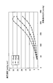
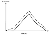
- FIG. 8 is a diagram showing the rate of change of the decompression speed with respect to the pressure of the air bladder 13 when the circumference of the measurement site is the same.
- the rate of change in the pressure reduction rate with respect to the pressure of the air bladder 13 differs depending on the gap of the valve 22, that is, the magnitude of the drive voltage.
- the rate of change in pressure reduction rate increases as the gap of valve 22 increases, and the rate of change in pressure reduction rate decreases as the gap decreases. Therefore, from the relationship shown in FIG. 8, the size of the gap is preferably such that the decompression speed of the air bag 13 from the calculation of the maximum blood pressure to the calculation of the minimum blood pressure is within a predetermined speed range. .
- the size of the gap is preferably such that the pressure reduction rate is such that the number of pressure pulse wave amplitude signals that can be detected between the systolic blood pressure and the systolic blood pressure during decompression is equal to or greater than a predetermined number. More preferably, the “predetermined number” is 5. This is because, as described in Japanese Patent No. 3179873 previously filed and filed by the applicant of the present application, a pressure pulse wave amplitude signal of about 5 is present between the maximum blood pressure and the minimum blood pressure during decompression. This is because it is considered appropriate to set the decompression measurement algorithm in consideration of the performance of the decompression measurement algorithm so that the decompression speed is controlled so that the number is measured.
- the size of the gap from which the number of pressure pulse wave amplitude signals of 5 or more is measured between the systolic blood pressure and the systolic blood pressure during decompression is obtained by, for example, experiments and stored in the drive voltage determination unit 412 in advance. It is assumed that Specifically, the value is preferably about 5 mmHg / sec to 20 mmHg / sec. Therefore, the coefficients ⁇ and ⁇ in the above equation (1) are values that make the blood pressure decompression speed within the range where the pressure of the air bladder 13 is about the blood pressure value within the decompression speed of about 5 mmHg / sec to 20 mmHg / sec. can do.
- Such coefficients ⁇ and ⁇ are obtained in advance through experiments or the like and are stored in the drive voltage determination unit 412.
- the drive voltage determination unit 412 inputs the circumference information acquired in the above equation (1) to determine the drive voltage E1, but the drive voltage determination unit 412 satisfies the equation (1).
- a table defining the relationship between the circumference information and the drive voltage E1 may be stored, and the drive voltage E1 corresponding to the circumference information acquired with reference to the table may be read.
- the CPU 40 determines the drive voltage E1 corresponding to the circumference in the drive voltage determination unit 412 and sends a control signal to drive the valve 22 while holding the determined drive voltage E1. 27 outputs a control signal.
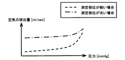
- controlling the drive voltage E1 to be constant means that the discharge amount from the valve 22 and the air It can be said that the drive voltage E1 is controlled so that the pressure reduction speed of the bag 13 is proportional.
- the flow rate of the air coming out of the air bladder 13 and the pressure reduction speed can be brought close to a proportional relationship.
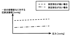
- the detection accuracy of the volume change of the blood vessel can be made almost constant, and the measurement accuracy can be improved. That is, as shown in FIG. 9C, regardless of the pressure change of the air bladder 13, the pressure pulse wave amplitude with respect to a constant volume change can be made constant at a value corresponding to the circumference of the measurement site.
- 10 and 11 are diagrams showing the relationship between changes in the internal pressure of the air bladder 8 and the internal pressure of the air bladder 13, in which the solid line indicates the internal pressure of the air bladder 13 and the dotted line indicates the internal pressure of the air bladder 8. Is shown.
- the air bag 8 is positioned between the air bag 8 and the air bag 13.
- the shape of the curler 10 is not stable and may be deformed. For example, as shown in FIG. 10, when the internal pressure of the air bag 8 becomes smaller than the internal pressure of the air bag 13, the compression strength of the air bag 8 against the curler 10 and the air bag 13 becomes smaller than the internal pressure of the air bag 13. As a result, the curler 10 is pushed outward by the internal pressure of the air bladder 13, and vibration due to the deformation is detected by being superimposed on a change in the internal pressure of the air bladder 13.
- the CPU 40 changes the internal pressure of the air bag 8 while maintaining a state in which the internal pressure of the air bag 8 is larger than the internal pressure of the air bag 13 by a predetermined ratio or more during measurement (here, when the pressure is reduced). By doing in this way, the curler 10 located between them is stabilized.
- step S23 the second control unit 42 of the CPU 40 monitors the internal pressure of the air bag 13 and the internal pressure of the air bag 8, and the internal pressure of the air bag 8 is the internal pressure of the air bag 13. Feedback control may be performed so that the predetermined ratio becomes a predetermined value.
- the second control unit 42 of the CPU 40 includes a drive voltage determining unit 422 for determining a voltage for driving the pump 31 and the valve 32 (hereinafter referred to as drive voltage E2), as shown in FIG. .
- the drive voltage determination unit 422 acquires the internal pressure of the air bladder 13 and the internal pressure of the air bladder 8 at a predetermined timing, and the internal pressure of the air bladder 8 becomes a predetermined ratio specified in advance of the internal pressure of the air bladder 13.
- the drive voltage E2 is determined.
- a control signal for driving the valve 32 with the determined drive voltage E ⁇ b> 2 is generated, and the control signal is output to the drive circuit 37.
- the predetermined ratio is a value determined in advance by an experiment or the like, and is stored in the second control unit 42 in advance.
- the internal pressure of the air bladder 13 may be subjected to the above-described feedback control by the first control unit 41 or may be subjected to feedforward control.
- the air bag 8 can be changed so that the internal pressure becomes a predetermined ratio of the internal pressure of the air bag 13 at the time of decompression.
- deformation of the curler 10 positioned between the air bag 13 and the air bag 8 at the time of measurement (at the time of decompression) can be prevented, and measurement accuracy can be improved.
- Feed-forward control the second control unit 42 of the CPU 40 is preset by the first control unit 41 when the first control unit 41 performs the above-described feed-forward control in step S23. You may perform feedforward control which outputs the control signal according to a control signal and controls the internal pressure of the air bag 8.
- feedforward control which outputs the control signal according to a control signal and controls the internal pressure of the air bag 8.
- the second control unit 42 of the CPU 40 includes a drive voltage determining unit 422 for determining the drive voltage E2 for driving the pump 31 and the valve 32, as shown in FIG.
- the drive voltage determination unit 422 acquires the determined drive voltage E1 by acquiring a control signal output from the first control unit 41. Then, a drive voltage E2 is calculated so that the internal pressure of the air bag 8 becomes a predetermined ratio of the internal pressure of the air bag 13 under the control, and is output to the drive circuits 36 and 37. Note that the predetermined ratio is a value determined in advance by an experiment or the like, and is stored in the second control unit 42 in advance.
- the air bag 8 The internal pressure can be changed to be a predetermined ratio of the internal pressure of the air bag 13. As a result, deformation of the curler 10 positioned between the air bag 13 and the air bag 8 at the time of measurement (at the time of decompression) can be prevented, and measurement accuracy can be improved.
- Ratio of internal pressure between air bag 13 and air bag 8 in feedforward control is a predetermined ratio determined in advance through experiments or the like. It is assumed that it is stored in the second control unit 42 in advance.
- the drive voltage determination unit 422 may calculate the predetermined ratio according to a predetermined input value, or store the correspondence between the input value and the predetermined ratio in advance, and set the predetermined ratio according to the input value. You may specify. Examples of the input value include the circumference of the measurement site, the blood pressure value of the user, the cuff size, and the maximum pressure value of the air bag 13. Each example of the input value will be described below.
- the 2nd control part 42 contains the acquisition part 421 for acquiring the circumference information which is the information which shows the circumference of the measurement site
- the acquisition unit 421 acquires the circumference of the measurement site in the same manner as the circumference information acquisition unit 411 described above. That is, for example, if circumference information such as “thick” or “thin” is input at the time of measurement by a switch or the like constituting the operation unit 3, the circumference information is acquired from the operation signal from the operation unit 3. Alternatively, the circumference information may be acquired by input from the external I / F 80.
- the internal pressure control for acquiring the circumferential length information may be performed in the CPU 40, and the acquisition unit 421 may acquire the circumferential length information according to the result.
- the internal pressure control for acquiring the circumference information is the same as the control for obtaining the circumference information by the circumference information acquisition unit 411.
- the drive voltage determination unit 422 stores a correspondence relationship or a relational expression between the circumference and the ratio of the internal pressure of the air bag 8 to the internal pressure of the air bag 13 in advance.
- FIG. 12 is a diagram illustrating a specific example of the relationship between the arm circumference as a specific example of the circumference and a predetermined ratio representing the ratio of the internal pressure between the air bag 13 and the air bag 8.
- the drive voltage determining unit 422 has a correspondence relationship or a relationship in which the ratio of the internal pressure of the air bag 8 to the internal pressure of the air bag 13 increases as the circumference of the measurement site increases. I remember the formula.
- the drive voltage determination unit 422 refers to the stored correspondence relationship, specifies the ratio corresponding to the circumference of the measurement site of the user acquired by the acquisition unit 421, and sets the internal pressure of the air bag 8 to the air bag 13.
- the driving voltage E2 is determined so as to be the ratio with respect to the internal pressure.
- the drive voltage E2 is calculated by substituting the circumference of the measurement site of the user acquired in the relational expression. Then, a control signal is generated and output.
- the internal pressure of the air bag 8 is controlled to be a ratio corresponding to the circumference of the measurement site of the user with respect to the internal pressure of the air bag 13.
- the 2nd control part 42 contains the acquisition part 421 for acquiring a user's blood-pressure value as FIG. 4 shows.
- the acquisition unit 421 acquires the estimated value of the blood pressure value in the pressurization process of the air bag 13 as the blood pressure value of the user.
- the calculation unit 43 calculates the blood pressure value of the user based on the change in the internal pressure during the pressurization process of the air bag 13 and inputs it to the second control unit 42 as an estimated value.
- the acquisition unit 421 may acquire the blood pressure value of the user by reading it from a predetermined area of the memory 7. In this case, the latest blood pressure value may be read out, or an average value of blood pressure values in a predetermined range may be used.
- the blood pressure value here may be a maximum blood pressure value, a minimum blood pressure value, or an average blood pressure value that is an average value of these values. In the following examples, the maximum blood pressure value is used.
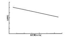
- the drive voltage determination unit 422 stores in advance a correspondence relationship or a relational expression between the blood pressure value and the ratio of the internal pressure of the air bladder 8 to the internal pressure of the air bladder 13. Specifically, the drive voltage determination unit 422 stores a correspondence relationship or relational expression in which the ratio of the internal pressure of the air bag 8 to the internal pressure of the air bag 13 decreases as the user's maximum blood pressure value increases.
- the drive voltage determination unit 422 refers to the stored correspondence relationship, identifies the ratio corresponding to the blood pressure value of the user acquired by the acquisition unit 421, and changes the internal pressure of the air bag 8 to the internal pressure of the air bag 13. On the other hand, the drive voltage E2 is determined so that the ratio is obtained. Alternatively, the drive voltage E2 is calculated by substituting the blood pressure value of the user acquired in the relational expression. Then, a control signal is generated and output.
- the internal pressure of the air bag 8 is controlled so as to become a ratio corresponding to the blood pressure value of the user with respect to the internal pressure of the air bag 13.
- the second control unit 42 obtains size information, which is information indicating the cuff size, as shown in FIG. 4 in order to set the ratio according to the cuff size.
- Size information which is information indicating the cuff size, as shown in FIG. 4 in order to set the ratio according to the cuff size.
- An acquisition unit 421 is included.
- the size of the cuff corresponds to the size of the volume of the air bags 13, 8.
- the size of the cuff is variable is, for example, the living body compression fixing device housed in the inner peripheral portion of the housing 60 or the housing 60 itself can be replaced with the main body 2, and the living body compression corresponding to the size of the cuff.
- the fixing device and the housing 60 including the fixing device are connected to the main body 2 are used.
- the acquisition unit 421 receives a cuff from the operation signal from the operation unit 3. Get the size of the.
- the cuff size may be acquired by input from the external I / F 80.
- the acquisition unit 421 receives from the sensor. The size of the cuff may be determined based on the output signal.
- the drive voltage determination unit 422 stores a correspondence relationship or a relational expression between the cuff size and the ratio of the internal pressure of the air bladder 8 to the internal pressure of the air bladder 13 in advance. Specifically, the drive voltage determination unit 422 stores a correspondence relationship or relational expression in which the ratio of the internal pressure of the air bladder 8 to the internal pressure of the air bladder 13 increases as the cuff size increases.
- the drive voltage determination unit 422 refers to the stored correspondence relationship, specifies the ratio corresponding to the cuff size acquired by the acquisition unit 421, and sets the internal pressure of the air bag 8 to the internal pressure of the air bag 13.
- a drive voltage E2 that determines the ratio is determined.
- the drive voltage E2 is calculated by substituting the acquired cuff size into the relational expression. Then, a control signal is generated and output.
- the internal pressure of the air bladder 8 is controlled to be a ratio corresponding to the cuff size with respect to the internal pressure of the air bladder 13.
- the 2nd control part 42 contains the acquisition part 421 for acquiring the highest pressurization value of the air bag 13, as FIG. 4 shows.
- the maximum pressure value of the air bag 13 indicates the maximum value of the internal pressure of the air bag 13 in the pressurizing process
- the acquisition unit 421 detects the internal pressure of the air bag 13 detected by the pressure sensor 23 in the pressurizing process. Is monitored to obtain the maximum pressure value of the air bladder 13.
- the acquisition unit 421 may calculate the maximum pressurization value from the blood pressure value of the user. In this case, the acquisition unit 421 acquires the blood pressure value of the user as described above.
- the drive voltage determination unit 422 stores in advance a correspondence relationship or a relational expression between the maximum pressurization value of the air bladder 13 and the ratio of the internal pressure of the air bladder 8 to the internal pressure of the air bladder 13. Specifically, the drive voltage determination unit 422 stores a correspondence relationship or relational expression in which the ratio of the internal pressure of the air bag 8 to the internal pressure of the air bag 13 decreases as the maximum pressure value of the air bag 13 increases. Yes.
- the drive voltage determination unit 422 refers to the stored correspondence relationship, specifies the ratio corresponding to the highest pressure value of the air bag 13 acquired by the acquisition unit 421, and sets the internal pressure of the air bag 8 to the air bag 13.
- the driving voltage E2 is determined so as to be the ratio with respect to the internal pressure. Alternatively, the drive voltage E2 is calculated by substituting the acquired maximum pressure value into the relational expression. Then, a control signal is generated and output.
- the internal pressure of the air bladder 8 is controlled to be a ratio corresponding to the maximum pressure value of the air bladder 13 with respect to the internal pressure of the air bladder 13.
- the drive voltage determination unit 422 receives, as an input value, any one of the circumference of the measurement site, the blood pressure value of the user, the cuff size, and the maximum pressurization value of the air bag 13.
- An example is given in which the ratio of the internal pressure of the air bag 8 to the internal pressure of the air bag 13 is specified.
- the predetermined ratio may be specified using a combination of two or more of them.
- the drive voltage determination unit 422 may specify a ratio according to the circumference of the user and the blood pressure value as the input value.
- the acquisition unit 421 acquires the circumference and blood pressure value of the user.
- the drive voltage determination unit 422 stores in advance a correspondence relationship or a relational expression between the circumference of the user and the blood pressure value and the ratio of the internal pressure of the air bag 8 to the internal pressure of the air bag 13.
- FIG. 14 shows a specific example of the relationship between the arm circumference as a specific example of the circumference, the maximum blood pressure value as a specific example of the blood pressure value, and a predetermined ratio representing the ratio of the internal pressure between the air bag 13 and the air bag 8.
- the drive voltage determination unit 422 increases the ratio of the internal pressure of the air bag 8 to the internal pressure of the air bag 13 as the circumference of the measurement site increases, and the maximum blood pressure A correspondence relationship or relational expression is stored such that the higher the value, the lower the ratio of the internal pressure of the air bag 8 to the internal pressure of the air bag 13.
- the drive voltage determination unit 422 refers to the stored correspondence relationship, specifies the ratio corresponding to the circumference and blood pressure value of the user acquired by the acquisition unit 421, and sets the internal pressure of the air bag 8 to the air bag 13.
- the driving voltage E2 is determined so as to be the ratio with respect to the internal pressure.
- the drive voltage E2 is calculated by substituting the circumference and blood pressure value of the user acquired in the relational expression. Then, a control signal is generated and output.
- the internal pressure of the air bladder 8 is controlled to be a ratio corresponding to the circumference of the user and the blood pressure value with respect to the internal pressure of the air bladder 13.
- the 2nd control part 42 determines the ratio of the internal pressure of the air bag 13 and the air bag 8 in feedforward control,
- the air pressure of the air bag 8 is changed according to a user or the condition at the time of a measurement. It is possible to set an optimum ratio with respect to the internal pressure. Thereby, the compression strength of the air bag 13 by the air bag 8 can be maintained at the time of measurement (at the time of pressure reduction) as the optimum, and the measurement accuracy can be improved.
- the second control unit 42 determines the ratio of the internal pressure of air bag 13 and air bag 8 during decompression. For example, it is determined at a predetermined timing such as the start of decompression, and a control signal that maintains the ratio determined at that timing thereafter is output.
- the second control unit 42 may change the determined ratio at a predetermined timing.
- the predetermined timing include the internal pressure of the air bladder 13 to be measured (or the pulse wave amplitude obtained from the internal pressure), the compression strength by the air bladder 8, and the elapsed time from the start of decompression.
- the second control unit 42 determines the internal pressure of the air bladder 13 (or the pulse wave amplitude obtained from the internal pressure), the compression strength by the air bladder 8, or the elapsed time from the start of decompression.
- An acquisition unit 421 for acquisition is included.
- the drive voltage determination unit 422 stores the predetermined ratio in advance for each internal pressure of the air bladder 13 (or pulse wave amplitude obtained from the internal pressure), compression strength by the air bladder 8, or every elapsed time from the start of decompression. . Then, whether or not the acquired internal pressure (or pulse wave amplitude obtained from the internal pressure) of the air bag 13, the compression strength by the air bag 8, or the elapsed time from the start of pressure reduction has reached the stored change timing. Are determined at predetermined intervals. When it is determined that the change timing has been reached, the drive voltage determination unit 422 reads a ratio corresponding to the timing, and the drive voltage is such that the internal pressure of the air bag 8 becomes the ratio relative to the internal pressure of the air bag 13. E2 is determined, and a control signal is generated and output.
- the second control unit 42 determines the predetermined timing when the rate of change of the internal pressure of the air bag 13 in the pressure section between the predetermined pressures P1 and P2 reaches a predetermined rate of change as the predetermined timing.
- the ratio may be changed.
- the pressure section includes a pressure section between the maximum pressurization value of the air bladder 13 and (the maximum pressurization value ⁇ 50 mmHg).
- the predetermined ratio may be changed according to the timing of combining two or more conditions.
- the drive voltage determination unit 422 stores in advance the relationship between the internal pressure of the air bag 13 and the compression strength of the air bag 8 and a predetermined ratio, and the internal pressure of the air bag 13 and the compression strength of the air bag 8 and the predetermined ratio You may change to the ratio specified according to the combination at the timing which reached the conditions.
- the air bag 8 is employed as a member for pressing the air bag 13 against the measurement site via the curler 10.
- FIG. 15 shows an outline of a sphygmomanometer 1 ′ according to the second embodiment.
- a wire 81 for pressing air bag 13 against the measurement site instead of air bag 8 and curler 10 of sphygmomanometer 1, and pump 31 and a valve 32, and a wire winding device 82 which is a mechanism for winding the wire 81 is provided.
- One end of the air bag 13 is fixed to the cuff, and the other end is connected to the wire.
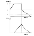
- FIG. 16 shows a change in the voltage (referred to as drive voltage E3) applied to the drive circuit of the wire take-up device 82 to drive the wire take-up device 82, and the air bag 13 in which the wire 81 presses against the measurement site.
- the upper diagram shows the change in the drive voltage E3
- the lower diagram shows the change in the internal pressure of the air bladder 13.
- the change in the drive voltage E ⁇ b> 3 and the change in the internal pressure of the air bladder 13 generally correspond to each other.
- the compression strength of the wire 81 to the air bladder 13 is controlled by controlling the drive voltage E3.
- the CPU 40 includes a first control unit 41, and the internal pressure of the air bladder 13 is feedback-controlled or feed-forward controlled by the first control unit 41 during decompression.
- the CPU 40 includes a second control unit 42, and the internal pressure of the air bag 8 may be feedback-controlled by the second control unit 42 at the time of depressurization, or when the internal pressure of the air bag 13 is feed-forward controlled. Forward control may be performed.
- each control is almost the same as those of the sphygmomanometer 1.
- the second control unit 42 controls the wire winding device 82 instead of controlling the pump 31 and the valve 32. Therefore, the drive voltage determination unit 422 of the second control unit 42 determines the drive voltage E3 in the same manner as the drive voltage E2 described above, and outputs a control signal.
- the second control unit 42 can adjust the compression strength.
- the deformation of the curler 10 positioned between the air bladder 13 and the compression member during measurement is prevented by outputting a control signal. Measurement accuracy can be improved.
- the CPU 40 calculates the blood pressure value based on the change in the internal pressure of the air bag 13 during the pressure reducing process.
- the CPU 40 may calculate the blood pressure value based on a change in internal pressure during the pressurizing process of the air bladder 13.
- the internal pressure control at the time of measurement can be made similar by setting “at the time of pressurization” to “at the time of pressurization” in the explanation of the internal pressure control.
- deformation of the curler 10 positioned between the air bag 13 and the compression member during measurement (pressurization) can be prevented, and measurement accuracy can be improved.
Landscapes
- Health & Medical Sciences (AREA)
- Life Sciences & Earth Sciences (AREA)
- Vascular Medicine (AREA)
- Cardiology (AREA)
- Biomedical Technology (AREA)
- Molecular Biology (AREA)
- Physiology (AREA)
- Biophysics (AREA)
- Pathology (AREA)
- Engineering & Computer Science (AREA)
- Ophthalmology & Optometry (AREA)
- Heart & Thoracic Surgery (AREA)
- Medical Informatics (AREA)
- Physics & Mathematics (AREA)
- Surgery (AREA)
- Animal Behavior & Ethology (AREA)
- General Health & Medical Sciences (AREA)
- Public Health (AREA)
- Veterinary Medicine (AREA)
- Dentistry (AREA)
- Measuring Pulse, Heart Rate, Blood Pressure Or Blood Flow (AREA)
Abstract
Description
<装置構成>
図1は、第1の実施の形態にかかる血圧測定装置(以下、血圧計)1の外観の具体例を示す斜視図である。
図4を参照して、血圧計1は空気袋13と空気袋8とを含み、それぞれ、測定用のエアー系20および圧迫固定用のエアー系30に接続されている。エアー系20には、空気袋13の内圧を測定するための圧力センサ23、空気袋13に対する給気/排気を行なうためのポンプ21、および弁22が、エアー系30には、空気袋8の内圧を測定するための圧力センサ33、空気袋8に対する給気/排気を行なうためのポンプ31、および弁32が含まれる。
図5は、第1の実施の形態にかかる血圧計1の血圧測定動作を示すフローチャートである。図5のフローチャートに示される血圧測定動作は、CPU40が空気袋13の減圧過程における内圧変化に基づいて血圧値を算出する場合の動作である。この動作は、操作部3の電源スイッチが押下されたことによってCPU40が操作信号を受信することによって開始され、CPU40がメモリ6に記憶されるプログラムを読出して実行し、図4に示される各部を制御することで実現される。
<空気袋13の内圧制御>
(1)フィードバック制御
上記ステップS23での減圧動作において、CPU40の第1制御部41は、空気袋13の内圧および内圧変化を監視し、それらの値が所定値となるように内圧の変化率を制御するような、フィードバック制御を行なってもよい。
または、CPU40の第1制御部41は、上記ステップS23での減圧動作において、予め設定された制御信号を出力して空気袋13の内圧および内圧変化を制御するような、フィードフォワード制御を行なってもよい。この、フィードフォワード制御を行なう場合について、詳細に説明する。
駆動電圧E1=α×周長情報+β …式(1)。
上記ステップS23での減圧動作において、CPU40は、空気袋8の内圧を空気袋13の内圧から所定割合となるように制御する。
上記ステップS23での減圧動作において、CPU40の第2制御部42は、空気袋13の内圧および空気袋8の内圧を監視し、空気袋8の内圧が空気袋13の内圧の所定割合が所定値となるようにフィードバック制御を行なってもよい。
または、CPU40の第2制御部42は、上記ステップS23で第1制御部41が上述のフィードフォワード制御を行なっている場合、第1制御部41の出力する予め設定された制御信号に応じた制御信号を出力して空気袋8の内圧を制御するような、フィードフォワード制御を行なってもよい。
上の例では、減圧時における空気袋13と空気袋8との内圧の割合を予め実験等で決定された所定割合であるものとし、予め第2制御部42に記憶されているものとしている。
この場合、第2制御部42は、図4に示されるように、使用者の測定部位の周長を示す情報である周長情報を取得するための取得部421を含む。
は、周長情報取得部411で周長情報を取得するための制御と同様である。
この場合、第2制御部42は、図4に示されるように使用者の血圧値を取得するための取得部421を含む。
カフのサイズが可変である場合、カフのサイズに応じた割合とするため、第2制御部42は、図4に示されるように、カフのサイズを示す情報であるサイズ情報を取得するための取得部421を含む。
この場合、第2制御部42は、図4に示されるように、空気袋13の最高加圧値を取得するための取得部421を含む。ここでの空気袋13の最高加圧値とは、加圧過程における空気袋13の内圧の最高値を指し、取得部421は、加圧過程において圧力センサ23で検出される空気袋13の内圧を監視することによって空気袋13の最高加圧値を取得する。
上の例は、駆動電圧決定部422が、入力値として、測定部位の周長、当該使用者の血圧値、カフのサイズ、および空気袋13の最高加圧値のうちのいずれか1つを用いて空気袋8の内圧を空気袋13の内圧に対する割合を特定する例を挙げている。しかしながら、上の例のうちのいずれか1つに限定されず、そのうちの2以上の組み合わせを用いて上記所定割合を特定してもよい。
上の例では、第2制御部42が、減圧時における空気袋13と空気袋8との内圧の割合を、たとえば減圧開始などの所定のタイミングに決定し、そのタイミングで決定された割合を以降維持するような制御信号を出力するものとしている。
第1の実施の形態にかかる血圧計1においては、空気袋13をカーラ10を介して測定部位に圧迫するための部材として空気袋8が採用されている。
Claims (12)
- 第1の流体袋と、
前記第1の流体袋に流体を可変な流速で注入/排出するための第1の調整装置と、
前記第1の流体袋の内圧を検出するためのセンサと、
前記第1の流体袋を被験者の測定部位に可変な巻き付け強度で巻き付けるための巻き付け装置と、
前記巻き付け装置の巻き付け強度を調整するための第2の調整装置と、
制御装置とを備え、
前記制御装置は、
前記第1の流体袋の内圧および/または流体量の変化率が所定の変化率となるように前記第1の調整装置に対して第1の制御信号を出力する第1の制御処理と、
前記巻き付け強度が前記第1の制御処理下における前記第1の流体袋の内圧および/または流体量の変化率と所定比率となるように第2の制御信号を前記第2の調整装置に対して出力する第2の制御処理と、
前記第1の制御処理下に検出される前記第1の流体袋の内圧変化に基づいて前記被験者の血圧値を算出する算出処理とを実行する、電子血圧計。 - 前記第1の制御信号は、前記第1の流体袋の内圧の変化率と前記第1の流体袋内の流体量の変化率とが比例関係になるように予め設定されており、
前記第2の制御信号は、前記所定比率となるよう前記第1の制御信号に応じて予め設定されており、
前記制御装置は、前記第1の制御処理および前記第2の制御処理を、フィードフォワード制御する、請求項1に記載の電子血圧計。 - 前記巻き付け装置は前記第1の流体袋よりも装着時に測定部位よりも遠い側に位置する第2の流体袋を含み、
前記第2の調整装置は、前記第2の流体袋に流体を可変な流速で注入するためのポンプおよび/または排出するための弁を含み、
前記第2の制御処理は、前記ポンプおよび/または前記弁の駆動電圧を決定する処理を含む、請求項1に記載の電子血圧計。 - 前記制御装置は、測定部位の周囲長、すでに測定された前記被験者の血圧値、加圧時に推定された前記被験者の血圧値、前記第1の流体袋の大きさ、および前記第1の流体袋内の圧力の最大値のうちの少なくとも1つに応じて前記所定比率を予め設定された比率に決定する、または、予め設定された補正式により変化させる、請求項1に記載の電子血圧計。
- 前記制御装置は、前記第1の流体袋の加圧時の内圧の変化率に基づいて前記測定部位の周囲長および/または前記第1の流体袋の大きさを決定する、請求項4に記載の電子血圧計。
- 前記制御装置は、以前の測定結果を取得することによって前記被験者の血圧値を決定する、請求項4に記載の電子血圧計。
- 前記制御装置は前記算出処理において、前記第1の流体袋の前記第1の制御処理下での減圧時の前記第1の流体袋の内圧変化に基づいて前記血圧値を算出し、
前記制御装置は、前記第1の流体袋の加圧時の前記第1の流体袋の内圧変化に基づいて算出される血圧値を前記所定比率を決定するために用いる前記被験者の血圧値とする、請求項4に記載の電子血圧計。 - 前記測定部位の周囲長、前記すでに測定された前記被験者の血圧値、前記第1の流体袋の大きさ、および前記第1の流体袋内の圧力の最大値のうちの前記少なくとも1つの入力を受け付けるための入力装置をさらに備える、請求項4に記載の電子血圧計。
- 前記測定部位の周囲長、前記すでに測定された前記被験者の血圧値、前記第1の流体袋の大きさ、および前記第1の流体袋内の圧力の最大値のうちの前記少なくとも1つを、他の装置から読み出すための読出装置をさらに備える、請求項4に記載の電子血圧計。
- 前記制御装置は、前記第1の流体袋の内圧が所定のレベルとなる時点、前記巻き付け強度が所定のレベルとなる時点、および測定処理の所定時点から所定の時間が経過した時点のうちの少なくとも1つにおいて、前記所定比率を予め設定された比率に変化させる、または、予め設定された補正式により変化させる、請求項1に記載の電子血圧計。
- 前記制御装置は、前記第1の流体袋の内圧から検出される脈波振幅の大きさに応じて前記所定比率を予め設定された比率に変化させる、または、予め設定された補正式により変化させる、請求項1に記載の電子血圧計。
- 電子血圧計の制御方法であって、
前記電子血圧計は、第1の流体袋と、前記第1の流体袋に流体を可変な流速で注入/排出するための第1の調整装置と、前記第1の流体袋の内圧を検出するためのセンサと、前記第1の流体袋を被験者の測定部位に可変な巻き付け強度で巻き付けるための巻き付け装置とを含み、
前記第1の流体袋の内圧および/または流体量の変化率が所定の変化率となるように前記第1の調整装置を制御するステップと、
前記巻き付け強度が前記第1の調整装置を制御するステップの制御下における前記第1の流体袋の内圧および/または流体量の変化率と所定比率となるように前記第2の調整装置を制御するステップと、
前記第1の調整装置を制御するステップの制御下に検出される前記第1の流体袋の内圧変化に基づいて前記被験者の血圧値を算出するステップとを備える、制御方法。
Priority Applications (3)
| Application Number | Priority Date | Filing Date | Title |
|---|---|---|---|
| CN201180035677.3A CN103025231B (zh) | 2010-07-21 | 2011-06-22 | 电子血压计 |
| DE112011102399.5T DE112011102399B4 (de) | 2010-07-21 | 2011-06-22 | Elektronisches Blutdruckmessgerät |
| US13/720,147 US9119538B2 (en) | 2010-07-21 | 2012-12-19 | Electronic sphygmomanometer |
Applications Claiming Priority (2)
| Application Number | Priority Date | Filing Date | Title |
|---|---|---|---|
| JP2010163942A JP5565164B2 (ja) | 2010-07-21 | 2010-07-21 | 電子血圧計 |
| JP2010-163942 | 2010-07-21 |
Related Child Applications (1)
| Application Number | Title | Priority Date | Filing Date |
|---|---|---|---|
| US13/720,147 Continuation US9119538B2 (en) | 2010-07-21 | 2012-12-19 | Electronic sphygmomanometer |
Publications (1)
| Publication Number | Publication Date |
|---|---|
| WO2012011353A1 true WO2012011353A1 (ja) | 2012-01-26 |
Family
ID=45496781
Family Applications (1)
| Application Number | Title | Priority Date | Filing Date |
|---|---|---|---|
| PCT/JP2011/064286 Ceased WO2012011353A1 (ja) | 2010-07-21 | 2011-06-22 | 電子血圧計 |
Country Status (5)
| Country | Link |
|---|---|
| US (1) | US9119538B2 (ja) |
| JP (1) | JP5565164B2 (ja) |
| CN (1) | CN103025231B (ja) |
| DE (1) | DE112011102399B4 (ja) |
| WO (1) | WO2012011353A1 (ja) |
Families Citing this family (12)
| Publication number | Priority date | Publication date | Assignee | Title |
|---|---|---|---|---|
| US9743847B2 (en) | 2013-03-15 | 2017-08-29 | St. Luke Medical, Inc. | Blood pressure cuff with tapered bladder |
| KR102384620B1 (ko) | 2013-10-04 | 2022-04-11 | 시쿼넘, 인코포레이티드 | 유전적 변이의 비침습 평가를 위한 방법 및 프로세스 |
| CN103584849B (zh) * | 2013-11-06 | 2015-11-11 | 康尚医疗技术(丹阳)有限公司 | 一种血压测量装置及脉搏信号检测方法 |
| CN103908238B (zh) * | 2014-04-16 | 2017-02-15 | 江苏物联网研究发展中心 | 血压数据校正方法、装置和电子血压计 |
| EP2997889B1 (en) * | 2014-09-16 | 2021-12-29 | Sean Gloth | Blood pressure cuff with tapered bladder |
| JP6830353B2 (ja) * | 2016-12-28 | 2021-02-17 | オムロン株式会社 | 血圧計および血圧測定方法並びに機器 |
| US20180206789A1 (en) * | 2017-01-24 | 2018-07-26 | Edwards Lifesciences Corporation | Extremity cuff such as a finger cuff, a method and a computer program product |
| JP7019415B2 (ja) * | 2017-12-28 | 2022-02-15 | オムロンヘルスケア株式会社 | 血圧測定装置 |
| KR102506146B1 (ko) * | 2020-06-22 | 2023-03-06 | 주식회사 바디프랜드 | 혈압을 측정하는 마사지 장치 및 이의 제어 방법 |
| JP7002020B1 (ja) * | 2020-09-25 | 2022-01-20 | LaView株式会社 | 生体情報測定装置 |
| CN116327148B (zh) * | 2021-12-23 | 2026-01-13 | 华为技术有限公司 | 一种血压测量设备及电子设备 |
| CN119632525A (zh) * | 2023-09-15 | 2025-03-18 | 华为技术有限公司 | 血压测量方法、系统、电子设备及介质 |
Citations (5)
| Publication number | Priority date | Publication date | Assignee | Title |
|---|---|---|---|---|
| JP2005230175A (ja) * | 2004-02-18 | 2005-09-02 | Omron Healthcare Co Ltd | 生体圧迫固定装置 |
| JP2005304670A (ja) * | 2004-04-20 | 2005-11-04 | Omron Healthcare Co Ltd | 電子血圧計 |
| JP2007167171A (ja) * | 2005-12-20 | 2007-07-05 | Omron Healthcare Co Ltd | 電子血圧計 |
| JP2009119067A (ja) * | 2007-11-15 | 2009-06-04 | Omron Healthcare Co Ltd | 動脈硬化度判定装置 |
| JP2010142418A (ja) * | 2008-12-18 | 2010-07-01 | Omron Healthcare Co Ltd | 電子血圧計 |
Family Cites Families (13)
| Publication number | Priority date | Publication date | Assignee | Title |
|---|---|---|---|---|
| US4905704A (en) * | 1989-01-23 | 1990-03-06 | Spacelabs, Inc. | Method and apparatus for determining the mean arterial pressure in automatic blood pressure measurements |
| JPH0767136B2 (ja) | 1989-09-21 | 1995-07-19 | 大日本スクリーン製造株式会社 | 画像処理装置 |
| JP3149873B2 (ja) | 1999-09-08 | 2001-03-26 | オムロン株式会社 | 電子血圧計 |
| JP3587837B2 (ja) * | 2002-09-27 | 2004-11-10 | コーリンメディカルテクノロジー株式会社 | 動脈硬化度評価装置 |
| JP3815487B2 (ja) * | 2004-04-26 | 2006-08-30 | オムロンヘルスケア株式会社 | 血圧測定用帯の巻付け制御装置 |
| CN101072536A (zh) * | 2004-10-11 | 2007-11-14 | 微生命知识产权股份有限公司 | 血压监测器和操作血压监测器的方法 |
| CN100488446C (zh) * | 2005-07-14 | 2009-05-20 | 优盛医学科技股份有限公司 | 智能型加压控制装置 |
| JP5228619B2 (ja) | 2008-05-22 | 2013-07-03 | オムロンヘルスケア株式会社 | 血圧測定装置 |
| JP2010075562A (ja) * | 2008-09-26 | 2010-04-08 | Terumo Corp | 電子血圧計及びその制御方法 |
| JP5187783B2 (ja) * | 2008-12-11 | 2013-04-24 | 株式会社エー・アンド・デイ | 自動血圧計 |
| WO2010073689A1 (ja) * | 2008-12-26 | 2010-07-01 | オムロンヘルスケア株式会社 | 電子血圧計および血圧測定方法 |
| RU2515860C2 (ru) * | 2009-02-06 | 2014-05-20 | Омрон Хэлткэа Ко., Лтд. | Устройство измерения кровяного давления, содержащее манжету, оборачиваемую вокруг места измерения |
| JP5589501B2 (ja) * | 2010-03-30 | 2014-09-17 | オムロンヘルスケア株式会社 | 血圧測定装置 |
-
2010
- 2010-07-21 JP JP2010163942A patent/JP5565164B2/ja active Active
-
2011
- 2011-06-22 DE DE112011102399.5T patent/DE112011102399B4/de active Active
- 2011-06-22 WO PCT/JP2011/064286 patent/WO2012011353A1/ja not_active Ceased
- 2011-06-22 CN CN201180035677.3A patent/CN103025231B/zh active Active
-
2012
- 2012-12-19 US US13/720,147 patent/US9119538B2/en active Active
Patent Citations (5)
| Publication number | Priority date | Publication date | Assignee | Title |
|---|---|---|---|---|
| JP2005230175A (ja) * | 2004-02-18 | 2005-09-02 | Omron Healthcare Co Ltd | 生体圧迫固定装置 |
| JP2005304670A (ja) * | 2004-04-20 | 2005-11-04 | Omron Healthcare Co Ltd | 電子血圧計 |
| JP2007167171A (ja) * | 2005-12-20 | 2007-07-05 | Omron Healthcare Co Ltd | 電子血圧計 |
| JP2009119067A (ja) * | 2007-11-15 | 2009-06-04 | Omron Healthcare Co Ltd | 動脈硬化度判定装置 |
| JP2010142418A (ja) * | 2008-12-18 | 2010-07-01 | Omron Healthcare Co Ltd | 電子血圧計 |
Also Published As
| Publication number | Publication date |
|---|---|
| DE112011102399T5 (de) | 2013-05-08 |
| CN103025231B (zh) | 2015-02-18 |
| CN103025231A (zh) | 2013-04-03 |
| JP2012024197A (ja) | 2012-02-09 |
| JP5565164B2 (ja) | 2014-08-06 |
| US9119538B2 (en) | 2015-09-01 |
| US20130109981A1 (en) | 2013-05-02 |
| DE112011102399B4 (de) | 2025-06-12 |
Similar Documents
| Publication | Publication Date | Title |
|---|---|---|
| JP5565164B2 (ja) | 電子血圧計 | |
| JP4325639B2 (ja) | 血圧測定装置 | |
| JP5811766B2 (ja) | 電子血圧計 | |
| JP5640527B2 (ja) | 血圧測定装置 | |
| JP3815487B2 (ja) | 血圧測定用帯の巻付け制御装置 | |
| US20110009757A1 (en) | Blood pressure information measurement device | |
| CN100393275C (zh) | 电子血压计 | |
| WO2007072647A1 (ja) | 血圧値を算出する電子血圧計 | |
| WO2010106994A1 (ja) | 血圧情報測定装置 | |
| CN102256539A (zh) | 电子血压计 | |
| JP5928341B2 (ja) | 電子血圧計および当該電子血圧計における血圧測定方法 | |
| CN103841883A (zh) | 电子血压计 | |
| JP5732692B2 (ja) | 血圧検出装置及び血圧検出方法 | |
| JP5741087B2 (ja) | 血圧情報測定装置 | |
| JP6136111B2 (ja) | 血圧測定装置 | |
| JP5111053B2 (ja) | 血圧測定装置 | |
| JP5228620B2 (ja) | 血圧測定装置 | |
| WO2013061778A1 (ja) | 電子血圧計 | |
| JP2012115413A (ja) | 電子血圧計 | |
| JP2009297223A (ja) | 血圧情報測定装置におけるカフ構造、および血圧情報測定装置 | |
| JP7823532B2 (ja) | 血圧計、および血圧測定方法 | |
| JP5405860B2 (ja) | 血圧計 | |
| JP2012196322A (ja) | 血圧測定装置 | |
| JP2024043197A (ja) | 血圧計、および血圧測定方法 |
Legal Events
| Date | Code | Title | Description |
|---|---|---|---|
| WWE | Wipo information: entry into national phase |
Ref document number: 201180035677.3 Country of ref document: CN |
|
| 121 | Ep: the epo has been informed by wipo that ep was designated in this application |
Ref document number: 11809527 Country of ref document: EP Kind code of ref document: A1 |
|
| WWE | Wipo information: entry into national phase |
Ref document number: 112011102399 Country of ref document: DE Ref document number: 1120111023995 Country of ref document: DE |
|
| 122 | Ep: pct application non-entry in european phase |
Ref document number: 11809527 Country of ref document: EP Kind code of ref document: A1 |
|
| WWG | Wipo information: grant in national office |
Ref document number: 112011102399 Country of ref document: DE |