WO2012005156A1 - 制動装置及び車両 - Google Patents
制動装置及び車両 Download PDFInfo
- Publication number
- WO2012005156A1 WO2012005156A1 PCT/JP2011/064953 JP2011064953W WO2012005156A1 WO 2012005156 A1 WO2012005156 A1 WO 2012005156A1 JP 2011064953 W JP2011064953 W JP 2011064953W WO 2012005156 A1 WO2012005156 A1 WO 2012005156A1
- Authority
- WO
- WIPO (PCT)
- Prior art keywords
- chamber
- hydraulic
- hydraulic pressure
- braking
- piston
- Prior art date
- Legal status (The legal status is an assumption and is not a legal conclusion. Google has not performed a legal analysis and makes no representation as to the accuracy of the status listed.)
- Ceased
Links
Images






Classifications
-
- B—PERFORMING OPERATIONS; TRANSPORTING
- B60—VEHICLES IN GENERAL
- B60T—VEHICLE BRAKE CONTROL SYSTEMS OR PARTS THEREOF; BRAKE CONTROL SYSTEMS OR PARTS THEREOF, IN GENERAL; ARRANGEMENT OF BRAKING ELEMENTS ON VEHICLES IN GENERAL; PORTABLE DEVICES FOR PREVENTING UNWANTED MOVEMENT OF VEHICLES; VEHICLE MODIFICATIONS TO FACILITATE COOLING OF BRAKES
- B60T11/00—Transmitting braking action from initiating means to ultimate brake actuator without power assistance or drive or where such assistance or drive is irrelevant
- B60T11/10—Transmitting braking action from initiating means to ultimate brake actuator without power assistance or drive or where such assistance or drive is irrelevant transmitting by fluid means, e.g. hydraulic
- B60T11/16—Master control, e.g. master cylinders
- B60T11/20—Tandem, side-by-side, or other multiple master cylinder units
-
- B—PERFORMING OPERATIONS; TRANSPORTING
- B62—LAND VEHICLES FOR TRAVELLING OTHERWISE THAN ON RAILS
- B62D—MOTOR VEHICLES; TRAILERS
- B62D63/00—Motor vehicles or trailers not otherwise provided for
- B62D63/02—Motor vehicles
- B62D63/04—Component parts or accessories
Definitions
- the present invention relates to a braking device and a vehicle that apply a braking force during deceleration.
- a vehicle such as an automobile is provided with a braking device such as a brake in order to decelerate and stop while traveling.
- the brake device decelerates and stops the vehicle by applying a load to the rotating tire, the axle, and the drive mechanism in a direction that suppresses rotation.
- roll stiffness variable means for changing the roll stiffness of the vehicle
- braking / driving force applying means for applying braking / driving force to the wheels
- a control means for calculating a yaw moment necessary to counter the extra yaw moment acting on the vehicle and controlling a braking / driving force difference between the left and right wheels so as to apply the necessary yaw moment to the vehicle.
- a vehicle running control device is described.
- the device described in Patent Literature 1 can improve straight traveling performance by adjusting the braking force of the left and right wheels as necessary.
- a device for adjusting the braking force there are ABS (Anti-lock Brake System) control and VCS (Vehicle Control System) control.
- the vehicle may be deflected during braking.
- the brake when the brake is applied, there may be a behavior that the vehicle stops while turning in one direction. Even in such a case, the deflection of the vehicle can be suppressed by controlling the braking force by the apparatus described in Patent Document 1, ABS control, or VCS control.
- the present invention has been made in view of the above, and an object of the present invention is to provide a braking device and a vehicle that can effectively suppress the deflection of the vehicle body during braking.
- the present invention is a drive device that applies a braking force to a first tire and a second tire that are rotatably arranged on a vehicle body, and supplies hydraulic pressure.
- a master cylinder having a first hydraulic pressure chamber and a second hydraulic pressure chamber, a piston for applying an external force to the first hydraulic pressure chamber and the second hydraulic pressure chamber, and a first hydraulic pressure chamber are supplied from the first hydraulic pressure chamber.
- a first hydraulic brake that applies a braking force to the first tire based on the hydraulic pressure
- a second hydraulic brake that applies a braking force to the second tire based on the hydraulic pressure supplied from the second hydraulic chamber.
- the stroke amount of the piston is increased, the difference in the ratio between the pressure of the first hydraulic pressure chamber and the pressure of the second hydraulic pressure chamber is determined by the stroke amount of the piston. It is characterized in that it is larger than the difference in pressure ratio when.
- the pressure of the first hydraulic pressure chamber and the pressure of the second hydraulic pressure chamber be the same pressure when the stroke amount of the piston is smaller than a set value.
- the pressure in the first hydraulic pressure chamber and the pressure in the second hydraulic pressure chamber are different from each other in the master cylinder.
- the master cylinder has a return spring or a multistage spring having a non-linear spring characteristic in at least one of the first hydraulic pressure chamber and the second hydraulic pressure chamber.
- the master cylinder has a sliding resistance generated in the first hydraulic chamber with respect to the movement of the piston and a sliding resistance generated in the second hydraulic chamber with respect to the movement of the piston. It is preferable to change according to the stroke amount of the piston.
- the master cylinder is arranged such that the first hydraulic chamber is closer to the end of the external force input side than the second hydraulic chamber than the second hydraulic chamber, and the second hydraulic chamber is connected to the piston. It is preferable to provide a resistance element that makes it difficult for the volume of the hydraulic chamber to decrease as the stroke amount increases.
- the present invention has a vehicle body and a braking device that applies a braking force to the vehicle body, and the braking device is in a state where a driver gets on the vehicle.
- the braking force closer to the center of gravity is set to be larger than the braking force farther from the center of gravity in the direction perpendicular to the traveling direction of the vehicle body, and the braking device is closer to the center of gravity when the braking force increases.
- the difference in the ratio between the braking force on the side and the braking force on the side far from the center of gravity is larger than the difference in the ratio between the braking force on the side near the center of gravity and the braking force on the side far from the center of gravity when the braking force is small. It is characterized by that.
- the vehicle further includes a first tire that is rotatably disposed on a side near the center of gravity of the vehicle body, and a second tire that is rotatably disposed on a side far from the center of gravity of the vehicle body
- the braking device includes: A master cylinder having a first hydraulic pressure chamber and a second hydraulic pressure chamber for supplying hydraulic pressure, and a first for applying a braking force to the first tire based on the hydraulic pressure supplied from the first hydraulic pressure chamber.
- a hydraulic braking unit and a second hydraulic braking unit that applies a braking force to the second tire based on the hydraulic pressure supplied from the second hydraulic chamber, and when the braking force increases, the first The pressure in the hydraulic chamber is configured to be higher than the pressure in the second hydraulic chamber.
- the master cylinder includes a first piston and a first cylinder constituting the first hydraulic pressure chamber, a first spring supporting the first piston, a second piston constituting the second hydraulic pressure chamber, and And a second spring that supports the second piston, and at least one of the first spring and the second spring has a non-linear spring characteristic, and when the braking force increases,
- the two springs preferably have a larger spring constant than the first spring.
- first tire and the second tire are forward in the traveling direction of the vehicle body.
- the braking device and the vehicle according to the present invention have an effect of effectively suppressing the deflection of the vehicle body during braking.
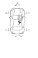
- FIG. 1 is a schematic diagram showing a schematic configuration of a vehicle having a braking device.
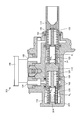
- FIG. 2 is a schematic diagram showing a schematic configuration of a master cylinder of the braking device.
- FIG. 3 is an explanatory diagram for explaining the force acting on the vehicle body during braking.
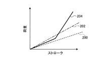
- FIG. 4 is a graph showing an example of the relationship between the load and stroke of the second spring.
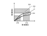
- FIG. 5 is a graph showing an example of the relationship between the first chamber hydraulic pressure and the second chamber hydraulic pressure.
- FIG. 6 is a graph showing another example of the relationship between the first chamber hydraulic pressure and the second chamber hydraulic pressure.
- FIG. 7 is a graph showing an example of the relationship between the use frequency of the braking device and the braking force.
- FIG. 1 is a schematic diagram showing a schematic configuration of a vehicle having a braking device.
- FIG. 2 is a schematic diagram showing a schematic configuration of a master cylinder of the braking device.
- FIG. 3 is an explanatory diagram for explaining the force
- FIG. 8 is a schematic diagram showing another example of the schematic configuration of the master cylinder of the braking device.
- FIG. 9 is a schematic diagram showing another example of the schematic configuration of the master cylinder of the braking device.
- FIG. 10 is a schematic diagram illustrating another example of the schematic configuration of the master cylinder of the braking device.
- FIG. 1 is a schematic diagram showing a schematic configuration of a vehicle having a braking device.
- the vehicle 10 includes a vehicle body 11, a left front tire 12, a right front tire 14, a left rear tire 16, a right rear tire 18, and a braking device 20.
- the vehicle 10 includes various configurations necessary for the vehicle, such as a drive source, a power transmission unit, an operation unit, and a seat.
- the vehicle body 11 is a housing of the vehicle 10, a so-called body. Inside the vehicle body 11, a drive source, a power transmission unit, an operation unit, a seat, and the like are provided.
- the left front tire 12, the right front tire 14, the left rear tire 16, and the right rear tire 18 are arranged on four sides of the vehicle body 11 and are in contact with the road surface.
- the left front tire 12, the right front tire 14, the left rear tire 16, and the right rear tire 18 are rotated by a driving source and a power transmission unit, thereby transmitting driving force to the road surface and moving the vehicle body 11 with respect to the road surface.
- the braking device 20 is doubled by a brake pedal 21 operated by the driver, a braking booster (brake booster) 22 that doubles the pedal depression force input to the brake pedal 21, and the braking booster 22.
- a master cylinder 23 that converts pedal depression force into hydraulic pressure (hydraulic pressure) of brake fluid
- a first hydraulic pipe 24 and a second hydraulic pipe 26 that distribute the hydraulic pressure supplied from the master cylinder 23
- the hydraulic brake units 28 lf , 28 rf , 28 lr , and 28 rr are arranged and generate a braking force by the hydraulic pressure supplied from the first hydraulic pipe 24 and the second hydraulic pipe 26.
- the first hydraulic pipe 24 is connected to the hydraulic braking unit 28 rf and the hydraulic braking unit 28 lr .
- the second hydraulic pipe 26 is connected to a hydraulic braking unit 28 lf and a hydraulic braking unit 28 rr .
- the hydraulic braking unit 28 lf applies a braking force to the left front tire 12
- the hydraulic braking unit 28 rf applies a braking force to the right front tire 14
- the hydraulic braking unit 28 lr applies to the left rear tire 16.
- a braking force is applied
- the hydraulic braking unit 28 rr applies a braking force to the right rear tire 18.
- the hydraulic brake 28 lf is prevented from rotating with a wheel cylinder 30 lf supplied with hydraulic pressure from the master cylinder 23 via the second hydraulic pipe 26, and a brake rotor 32 lf rotating with the wheel (left front tire 12).
- Hydraulic brake 28 lf is the above configuration, when the higher hydraulic from the master cylinder 23 (hydraulic pressure of braking) is supplied, the wheel cylinders 30 lf presses the brake pad 34 lf the brake rotor 32 lf Move in the direction. As a result, the brake pad 34lf and the brake rotor 32lf are brought into contact with each other, and a force in a direction in which the rotation is stopped is applied to the brake rotor 32lf . In this way, the hydraulic brake 28 lf applies the braking force to the tires arranged to face each other by the hydraulic pressure supplied from the master cylinder 23.
- the hydraulic brake unit 28 rf, 28 lr, 28 rr, the arrangement positions (tire arranged corresponding) is only different, is basically the hydraulic braking unit 28 lf the same configuration.
- the position of the wheel cylinder 30 rf is fluctuated by the hydraulic pressure supplied from the first hydraulic pipe 24, and the hydraulic brake unit 28 rf is supplied with high hydraulic pressure from the first hydraulic pipe 24 to the wheel cylinder 30 rf during braking.
- a braking force is applied to the right front tire 14 by bringing the brake pad 34 rf and the brake rotor 32 rf into contact with each other.
- the position of the wheel cylinder 30 lr is fluctuated by the hydraulic pressure supplied from the first hydraulic pipe 24, and the hydraulic brake unit 28 lr is supplied with high hydraulic pressure from the first hydraulic pipe 24 to the wheel cylinder 30 lr during braking, A braking force is applied to the left rear tire 16 by bringing the brake pad 34 lr into contact with the brake rotor 32 lr .
- the hydraulic brake unit 28 rr changes the position of the wheel cylinder 30 rr by the hydraulic pressure supplied from the second hydraulic pipe 26, and a high hydraulic pressure is supplied from the second hydraulic pipe 26 to the wheel cylinder 30 rr during braking, A braking force is applied to the right rear tire 18 by bringing the brake pad 34 rr into contact with the brake rotor 32 rr .
- FIG. 2 is a schematic diagram showing a schematic configuration of the master cylinder of the braking device.
- the master cylinder 23 includes a cylinder 112, an input piston 113, a pressurizing piston 115, a first spring 138, a second spring 139, and a reservoir tank 146.
- the cylinder 112 has a cylindrical shape with an open base end and a closed end, and an input piston 113 and a pressurizing piston 115 are coaxially arranged inside and are supported so as to be movable in the axial direction. .
- the input piston 113 is movably supported on the inner peripheral surface of which the outer peripheral surface forms the cylindrical shape of the cylinder 112.
- the input piston 113 has a braking booster 22 (see FIG. 1) connected to a base end (base end side of the cylinder 112).
- the input piston 113 has a cylindrical portion whose outer peripheral surface is in contact with the cylinder 112 and a first piston 120 disposed inside the cylindrical portion on the distal end side.
- the first piston 120 is provided with a disc having a diameter larger than that of the other part at the tip. That is, the first piston 120 has a shape in which one end of a rod-shaped member is connected to the base end of the input piston 113 and a disk is provided at the other end.
- the pressurizing piston 115 is disposed on the tip end side of the input piston 113 in the cylinder 112, and an outer peripheral surface thereof is movably supported on the inner peripheral surface of the cylinder 112.
- the pressurizing piston 115 is provided with a first cylinder 122 on the input piston 113 side.
- the first cylinder 122 is a cylindrical member, and the tip of the first piston 120, that is, a disk is inserted.
- the first cylinder 122 has a cylindrical inner diameter that is substantially the same as that of the disk of the first piston 120, and an end portion on the input piston 113 side is smaller in diameter than other portions. That is, the first cylinder 122 has a shape in which the distal end portion of the first piston 120 does not come off.
- the proximal region of the first cylinder 122 and the space formed by the first piston 120 is the first chamber (first pressure chamber) R 1.
- the first chamber R 1 is connected to the first hydraulic pipe 24 via a pipe not shown.
- the shape of the pressure piston 115 on the front end side is substantially the same as that on the front end portion side of the input piston 113, and a cylindrical portion whose outer peripheral surface is in contact with the cylinder 112 and a second piston disposed inside the cylindrical portion. 124 is arranged.
- the second piston 124 is also provided with a disk having a larger diameter than the other part at the tip.
- a second cylinder 126 is provided at a base end portion of the cylinder 112 inside the cylinder 112, that is, at a portion facing the pressurizing piston 115.
- the second cylinder 126 is a cylindrical member, and the tip of the second piston 124, that is, a disk is inserted.
- the second cylinder 126 is fixed to the cylinder 112.
- the second cylinder 126 also has an inner diameter of the cylinder substantially the same as that of the disk of the second piston 124, and an end portion on the pressure piston 115 side is smaller in diameter than other portions. That is, the second cylinder 126 has such a shape that the tip of the second piston 124 does not come off.
- area and space formed by the second piston 124 on the base end side of the second cylinder 126 is a second chamber (second pressure chamber) R 2.
- the opening area A 2 is a opening area A 1 and the same area.
- the second chamber R 2 is connected to the second hydraulic pipe 26 via a pipe not shown.
- the first spring 138 is disposed between the input piston 113 and the pressurizing piston 115. Specifically, it is disposed on the inner periphery of the cylindrical portion of the input piston 113 and the outer periphery of the first cylinder 122 of the pressurizing piston 115.
- the first spring 138 is a return spring, and applies an urging force in a direction in which the input piston 113 and the pressure piston 115 are separated in the axial direction.
- the first spring 138 is a spring having non-linear spring characteristics. The spring characteristics of the first spring 138 will be described later.
- the second spring 139 is disposed between the pressure piston 115 and the base end portion of the cylinder 112. Specifically, it is disposed on the inner periphery of the cylindrical portion of the pressurizing piston 115 and the outer periphery of the second cylinder 126 of the cylinder 112.
- the second spring 139 is also a return spring, and applies an urging force in a direction in which the pressurizing piston 115 and the base end portion of the cylinder 112 are separated in the axial direction.
- the reservoir tank 146 is a tank that stores hydraulic oil.
- a relief pipe 155 and a relief pipe 159 are formed in the cylinder 112.
- the relief pipe 155 connects the reservoir tank 146 with a space between the input piston 113 and the pressurizing piston 115 (a space where the first spring 138 is disposed).
- the relief pipe 159 connects the reservoir tank 146 with a space between the pressurizing piston 115 and the cylinder 112 (a space where the second spring 139 is disposed).
- hydraulic oil is supplied to the two spaces inside the cylinder 112.
- two seal members 163 are arranged in the contact portion between the input piston 113 and the cylinder 112 so that the portion in which the relief pipe 155 supplies the hydraulic oil to the space described above is sandwiched in the axial direction.
- the seal member 163 suppresses the hydraulic oil from leaking between the input piston 113 and the cylinder 112.
- Two seal members 162 are arranged at the contact portion between the pressurizing piston 115 and the cylinder 112 so as to sandwich a portion where the relief pipe 159 supplies the hydraulic oil to the space described above in the axial direction.
- the seal member 162 suppresses leakage of hydraulic oil from between the pressure piston 115 and the cylinder 112.
- the master cylinder 23 is configured as described above.
- the operating force (stepping force) is transmitted to the brake booster 22, and the operating force is boosted and transmitted to the master cylinder 23. Is done.
- the input piston 113 when advanced against the urging force of the first spring 138, the first chamber R 1 is pressurized. Then, the hydraulic pressure in the first chamber R 1 is discharged to the first hydraulic pipe 24.
- the input piston 113 moves forward, the input piston 113 presses the pressure piston 115 via the first spring 138 and the first chamber R 1, the pressure piston 115 against the biasing force of the second spring 139 And move forward. Then, the second chamber R 2 is pressurized, and the hydraulic pressure in the second chamber R 2 is discharged to the second hydraulic pipe 26.
- the vehicle 10 is configured as described above, and when the occupant steps on the brake pedal 21, hydraulic pressure is discharged from the master cylinder 23 to the first hydraulic pipe 24 and the second hydraulic pipe 26.
- the first chamber oil pressure discharged from R 1 in the master cylinder 23 via the first hydraulic pipe 24, is supplied to the hydraulic brake unit 28 rf and the hydraulic brake unit 28 lr.
- Second chamber oil pressure discharged from R 2 of the master cylinder 23 via the second hydraulic pipe 26, is supplied to the hydraulic brake unit 28 lf and the hydraulic brake unit 28 rr.
- the hydraulic pressure is discharged from the master cylinder 23 to each hydraulic braking unit, so that the brake pad comes into contact with the brake rotor of each hydraulic braking unit and applies a braking force to the tire.
- the vehicle 10 is decelerated and stopped.
- the braking force is applied to each tire by the braking device 20 in the vehicle 10. That is, as shown in FIG. 3, the left front tire 12 is given a braking force Fxlf by the hydraulic braking portion 28 lf , and the right front tire 14 is given a braking force Fxrf by the hydraulic braking portion 28 rf. the is the braking force Fxlr is imparted by the hydraulic brake unit 28 lr, braking force Fxrr is applied by the hydraulic brake unit 28 rr and the right rear tire 18.
- FIG. 3 is an explanatory diagram for explaining the force acting on the vehicle body during braking. During braking, a larger braking force is applied to the front wheels.
- the braking force Fxlf and the braking force Fxrrf are larger than the braking force Fxlr and the braking force Fxrr.
- the vehicle 10 has a center of gravity g shifted from the center (center) to the right side (right tire side) in the direction orthogonal to the traveling direction in a state where the driver (driver) is in the vehicle. Position. Therefore, the distance between the left tire (left front tire 12 and left rear tire 16) and the center of gravity g in the direction orthogonal to the traveling direction is Lwl, and the right tire (right front tire 14 and right rear tire 18) and center of gravity g The distance from is Lwr.
- the relationship between the distance Lwl and the distance Lwr is Lwr ⁇ Lwl.
- the vehicle 10 of the present embodiment changes the rotation moment by setting the hydraulic pressure generated in the first chamber R 1 and the hydraulic pressure generated in the second chamber R 2 to be different during braking.
- the generation of Mz is suppressed, and the vehicle 10 is prevented from being deflected during braking.
- the braking device 20 of the vehicle 10 will be described with reference to FIGS. 4 to 7.
- FIG. 4 is a graph showing an example of the relationship between the load and stroke of the second spring.
- the horizontal axis is the stroke and the vertical axis is the load.
- the stroke is a contraction amount of the second spring 139. 4
- the line segment 200 showing the same spring characteristics as the first spring 138 and the first spring 138 are less likely to be deformed ( A line segment 202 indicating the spring characteristic is also shown.
- the second spring 139 is a spring having a non-linear spring characteristic as indicated by a line segment 204 shown in FIG. As shown by the line 204 in FIG. 4, the second spring 139 has a smaller stroke amount with respect to the load when the stroke exceeds a certain value. That is, when the second spring 139 is contracted by a certain distance or more, it is difficult to contract further.
- the amount of contraction of the second spring 139 is the amount of movement of the second piston 124 relative to the second cylinder 126, that is, the amount of relative movement between the second cylinder 126 and the second piston 124. .
- the master cylinder 23 an external force is applied from the input piston 113, a first piston 120, a pressure piston 115, and the second piston 124 is relatively moved, the first chamber R 1 and the second chamber R 2 volume is reduced, when the volume of the second chamber R 2 becomes equal to or less than a predetermined volume, is less likely to shrink the second spring 139.
- the less likely shrinkage second spring 139 the amount of decrease in the second chamber volume R 2 is reduced to forces input thereto.
- the amount of decrease in the volume of the second chamber R 2 is relatively smaller than the amount of decrease in the volume of the first chamber R 1 , so that the hydraulic pressure discharged from the second chamber R 2 is reduced to the first chamber R 1. It becomes lower than the hydraulic pressure discharged from.
- FIG. 5 is a graph showing an example of the relationship between the first chamber hydraulic pressure and the second chamber hydraulic pressure.
- the horizontal axis is the hydraulic pressure (hydraulic pressure) [MPa] of the first chamber
- the vertical axis is the hydraulic pressure (hydraulic pressure) [MPa] of the second chamber.
- a region 210 shown in FIG. 5 is a region where the amount of depression of the brake pedal is small, that is, a region where the external force from the input piston 113 of the master cylinder 23 is small
- a region 212 is a region where the amount of depression of the brake pedal is large.
- both the first chamber hydraulic pressure and the second chamber hydraulic pressure are low, and in the region 212, both the first chamber hydraulic pressure and the second chamber hydraulic pressure are higher than those in the region 210.
- a thick line 214 shown in FIG. 5 shows an example of a pressure change when the brake pedal 21 is actually depressed and then released.
- a dotted line 216 shown in FIG. 5 is a line showing a relationship in which the first chamber hydraulic pressure and the second chamber hydraulic pressure change on a one-to-one basis, and a straight line 218 indicates the rate of change of the first chamber hydraulic pressure. It is a line which shows the relationship higher than the rate of change of the two-chamber hydraulic pressure by a certain percentage.
- the master cylinder 23 indicates that the first chamber hydraulic pressure and the second chamber hydraulic pressure are a pair indicated by a dotted line 216 as indicated by a thick line 214 in the region 210 of FIG. The value is close to 1. Thereafter, when the depression amount of the brake pedal 21 becomes large and the stroke amount (contraction amount) of the second spring 139 exceeds a certain value, the second spring 139 turns the first spring 139 into the first spring. Compared to 138, the amount of contraction with respect to the received force is reduced. Therefore, in the master cylinder 23, when the depression of the brake pedal 21 exceeds a certain level, the first chamber hydraulic pressure becomes larger than the second chamber hydraulic pressure as indicated by a thick line 214 in the region 212 of FIG.
- the change rate of the first chamber hydraulic pressure is larger than the change rate of the second chamber hydraulic pressure.
- the difference in the ratio between the first chamber hydraulic pressure and the second chamber hydraulic pressure in the region 212 is larger than the difference in the ratio between the first chamber hydraulic pressure and the second chamber hydraulic pressure in the region 210,
- the relationship is closer to the straight line 218 than to the dotted line 216.
- the pressure in the first chamber is higher than the pressure in the second chamber.
- the second chamber R 2 is towards the first chamber R 1 has set a supplying higher fluid pressure. More specifically, when the depression amount becomes a certain level or more, the difference in the ratio between the first chamber fluid pressure and the second chamber fluid pressure is such that the first chamber fluid pressure and the second chamber fluid when the depression amount is less than a certain amount. It becomes larger than the difference in the ratio to the pressure.
- FIG. 6 is a graph showing another example of the relationship between the first chamber hydraulic pressure and the second chamber hydraulic pressure.
- the horizontal axis is the hydraulic pressure (hydraulic pressure) [MPa] of the first chamber
- the vertical axis is the hydraulic pressure (hydraulic pressure) [MPa] of the second chamber.
- the graph shown in FIG. 6 is an example when a spring satisfying the relationship of the line segment 202 shown in FIG. 4 is used as the second spring. That is, the graph shown in FIG.
- the hydraulic pressure generated in the first chamber R 1 and the second chamber R 2 is a graph showing the relationship between the hydraulic pressure discharged to the second hydraulic pipe 26.
- a thick line 220 also shows an example of a pressure change when the brake pedal 21 is actually depressed and then released.
- FIG. 6 is a line showing a relationship in which the first chamber hydraulic pressure and the second chamber hydraulic pressure change on a one-to-one basis, and a straight line 218 indicates the rate of change in the first chamber hydraulic pressure. It is a line which shows the relationship higher than the rate of change of the two-chamber hydraulic pressure by a certain percentage. Note the thick line 220, about the relations of the straight line 218, i.e. the relationship between the first chamber of the R 1 fluid pressure and a second chamber of the R 2 hydraulic based on the ratio of the linear 218 is changed. As shown in FIG. 6, when the spring characteristic of the first spring is linear as shown by the line segment 202 shown in FIG. 4, the first chamber R 1 has a higher hydraulic pressure than the second chamber R 2. Can be supplied.
- the braking device 20 and the vehicle 10 having the braking device 20 generate the hydraulic pressure by the master cylinder 23, thereby generating the braking force Fxrf and the braking force Fxlr from the braking force Fxlf and the braking force Fxrr.
- the component of (Fxrf + Fxrr) ⁇ Lwr can be further increased and the component of (Fxlf + Fxrr) ⁇ Lwl can be further decreased, so that the generated rotation moment Mz can be reduced.
- the rotational moment Mz can be made smaller and ideally zero.
- the braking device 20 and the vehicle 10 with it by putting a difference in hydraulic pressure generated in the first chamber R 1 and the second chamber R 2, is possible to reduce the rotational moment Mz generated during braking This can suppress the deflection of the vehicle 10 during braking.
- the vehicle 10 and the braking device 20 generate a difference in the braking force generated by a mechanical structure (that is, as a reference setting and an initial setting). For this reason, when adjusting the braking force using a sensor or the like, the time zone during which control is not possible, that is, the initial stage of braking (between the start of calculation at the start of braking and the start of braking force control) The rotational moment Mz can be reduced.
- deflection at the time of braking is likely to occur. it can.
- the second spring 139 has the characteristic shown by the line 204 in FIG. 4, and the thick line 214 in FIG. 5 with respect to the depression amount of the brake pedal.
- the first chamber hydraulic pressure and the second chamber hydraulic pressure are generated according to the relationship shown in FIG. Thereby, when the depression amount of the brake pedal is small, that is, when the braking force is small, the difference (ratio of the ratio) between the first chamber hydraulic pressure and the second chamber hydraulic pressure is reduced, and when the braking force is large.
- the difference (ratio difference) between the first chamber hydraulic pressure and the second chamber hydraulic pressure can be increased.
- FIG. 7 is a graph showing an example of the relationship between the use frequency of the braking device and the braking force.
- the horizontal axis is the braking force (braking G), and the vertical axis is the frequency.
- the braking device 20 frequently performs a braking operation with a small braking force, that is, a braking operation that generates a hydraulic pressure in the region 210 shown in FIG. 5.
- the braking device 20 performs the braking operation with a large braking force, that is, the braking operation for generating the hydraulic pressure in the region 212 shown in FIG. 5 only a certain number of times.
- the braking operation with a small braking force is often a smooth stopping operation or a stopping / decelerating operation performed in an expected state during stable traveling.
- a braking operation with a large braking force is often an emergency operation such as a sudden braking.
- a braking operation with a large braking force becomes a braking stability influence region 230 that has a large influence on the braking stability.
- the braking operation with a small braking force has a large influence on the wear of the braking device, mainly tires, brake pads, etc., because it is used many times. For this reason, a braking operation with a small braking force is a wear-affected area that has a large influence on wear. The braking operation with a large braking force has a small influence on the wear because it is used less frequently.
- the braking device 20 of the present embodiment and the vehicle 10 having the same make the spring characteristics of the second spring 139 non-linear, and in the wear-affected area 232, that is, the area 210 of FIG.
- the ratio to the chamber hydraulic pressure By setting the ratio to the chamber hydraulic pressure to a state close to 1: 1, it is possible to suppress uneven wear of the left and right corresponding parts of the braking device. That is, it is possible to suppress the occurrence of uneven wear, in which only one of the left and right corresponding parts is greatly worn.
- the difference (ratio in the ratio) between the first chamber hydraulic pressure and the second chamber hydraulic pressure is large in the braking stability influence region, that is, in the region 212.
- the braking device 20 according to the present embodiment and the vehicle 10 having the braking device can increase the braking stability and generate uneven wear when the braking force is large and high braking stability is required. Can be suppressed. That is, braking stability and suppression of occurrence of uneven wear (improvement of device durability) can be realized in an appropriate balance according to the state of use.
- the second spring as a non-linear spring, the difference in the ratio between the first chamber hydraulic pressure and the second chamber hydraulic pressure in the wear affected zone 232 and the braking stability affected zone 230 is increased.
- the present invention is not limited to this.
- the difference in the ratio between the first chamber hydraulic pressure and the second chamber hydraulic pressure varies between the wear affected area 232 and the braking stability affected area 230, that is, between one brake section and the other brake section.
- Various configurations in which the difference in the ratio of the braking force to be generated can be used.
- FIGS. 8 to 10 are schematic views showing other examples of the schematic configuration of the master cylinder of the braking device. Further, the master cylinder shown in FIGS. 8 to 10 is the same as the master cylinder shown in FIG. 2 except that a configuration replacing the second spring as a non-linear spring is added. Therefore, in the following, a configuration unique to the master cylinder in each figure will be described.
- the second springs 139 of the master cylinder shown in FIGS. 8 to 10 are all linear springs.
- the eighth has a third spring 310 inside the second cylinder 126.
- the third spring 310 is a hollow spring, and is disposed along the second cylinder 126 inside the second cylinder 126.
- the third spring 310 is a member that is shorter than the length of the second cylinder 126 in the axial direction, and one end is disposed on the second piston 124 side, and the other end is the input piston 113 of the cylinder 112. It is arrange
- the master cylinder 302 when an external force is applied from the input piston 113, that is, when the brake pedal 21 is depressed, the first piston 120 and the first cylinder 122 move relatively.
- the volume of the second chamber R 2 is moved from the maximum state to decrease direction.
- the third spring 310 even if the volume of the second chamber R 2 is reduced to a volume of the second chamber R 2 becomes constant volume, in a state where the moving direction does not exert a force of the second piston 124, a second cylinder 126 is disposed between the second piston 124 and the cylinder 112 in 126.
- the master cylinder 302 while decreasing the second chamber volume of R 2, the first chamber volume of R 1 also reduces. As a result, the predetermined hydraulic pressure is discharged as described above.
- the master spring 302 comes into contact with the second piston 124 and the cylinder 112 at both ends, respectively. Thereafter, when an external force is further applied from the input piston 113, that is, when the brake pedal 21 is depressed, the third spring 310 gradually contracts. At this time, the third spring 310 serves as a resistance against relative movement between the second piston 124 and the second cylinder 126.
- the master cylinder 302 the volume of the second chamber R 2 becomes less than a certain volume, relative to the amount of decrease in the second chamber volume R 2, possible to increase the amount of decrease in the first chamber volume R 1 Can do.
- the third pedal 310 is provided as in the master cylinder 302, that is, the spring is provided in multiple stages, the amount of depression of the brake pedal 21 is equal to or larger than a certain level as described above. That is, when the braking force becomes a certain level or more, the difference in the hydraulic pressure ratio can be further increased. That is, the difference in braking force can be increased.
- the second cylinder 326 determines the surface roughness (surface roughness) of the area 324 on the cylinder 112 side (the opposite side to the second piston 124 side) of the inner surface of the input piston 113 (first piston).
- the surface roughness of the area on the 1 piston 120) side is rougher.
- the master cylinder 320 when an external force is applied from the input piston 113, that is, when the brake pedal 21 is depressed, the second piston 124 and the second cylinder 326 move relatively.
- the first chamber volume R 1 is moved from the maximum state to decrease direction.
- the master cylinder 320 moves relative to the second chamber R while the second piston 124 and the second cylinder 326 slide.
- the volume of 2 decreases.
- the master cylinder 320 while decreasing the second chamber volume of R 2, the first chamber volume of R 1 also reduces. Thereby, the predetermined hydraulic pressure is discharged as described above.
- the master cylinder 320 the volume of the second chamber R 2 becomes less than a certain volume, the tip of the second piston 124 is in contact with the region 324 of the second cylinder 326. Thereafter, when an external force is further applied from the input piston 113, that is, when the brake pedal 21 is depressed, the tip of the second piston 124 moves while contacting the region 324 of the second cylinder 326. At this time, since the area 324 has a rougher surface than the other areas, it is a resistance against the relative movement of the second piston 124 and the second cylinder 326. Thus, the master cylinder 320, the volume of the second chamber R 2 becomes less than a certain volume, relative to the amount of decrease in the second chamber volume R 2, possible to increase the amount of decrease in the first chamber volume R 1 Can do.
- the amount of depression of the brake pedal is not less than a certain value, as described above.
- the difference in the hydraulic pressure ratio can be further increased. That is, the difference in braking force can be increased.
- the master cylinder 340 shown in FIG. 10 has a configuration in which the second cylinder 342 is provided with a protrusion 344 having a shorter diameter on the cylinder 112 side than the input piston 113 (second piston 124) side.
- the protrusion 344 has a deformable shape and serves as resistance for passage of the second piston 124, but does not make the second piston 124 immovable. That is, the second piston 124 can move toward the cylinder 112 with respect to the second cylinder 342 while contacting the protrusion 344.
- the master cylinder 340 when an external force is applied from the input piston 113, that is, when the brake pedal 21 is depressed, the second piston 124 and the second cylinder 342 move relatively.
- the volume of the second chamber R 2 is moved from the maximum state to decrease direction.
- the master cylinder 340 moves relative to the second chamber while the second piston 124 and the second cylinder 342 slide.
- volume of R 2 is reduced.
- the master cylinder 340 while decreasing the second chamber volume of R 2, the first chamber volume of R 1 also reduces. As a result, the predetermined hydraulic pressure is discharged as described above.
- the master cylinder 340 the volume of the second chamber R 2 becomes less than a certain volume, the tip of the second piston 124 is in contact with the protrusions 344 of the second cylinder 342. Thereafter, when an external force is further applied from the input piston 113, that is, when the brake pedal is depressed, the tip of the second piston 124 moves while contacting the protrusion 344 of the second cylinder 342. At this time, the protrusion 344 has a resistance to relative movement between the second piston 124 and the second cylinder 342 because the diameter of the second cylinder 342 is smaller than that of the other region.
- the master cylinder 340 the volume of the second chamber R 2 becomes less than a certain volume, relative to the amount of decrease in the second chamber volume R 2, possible to increase the amount of decrease in the first chamber volume R 1 Can do.
- the difference in hydraulic pressure ratio can be further increased. That is, the difference in braking force can be increased.
- the shape of the protrusion is not particularly limited. Also, the shape is not particularly limited.
- the rotational moment Mz is calculated from the braking force of the four wheels constituting the vehicle, and the hydraulic pressure difference that suppresses the rotational moment Mz that occurs when the driver is on the vehicle is calculated.
- the hydraulic pressure difference that suppresses the rotational moment Mz may be calculated only with the front wheel that becomes larger.
- the braking device does not generate a hydraulic pressure difference between the first chamber and the second chamber in the wear-affected area (the area where the braking force and the hydraulic pressure are low), that is, between the first chamber hydraulic pressure and the second chamber hydraulic pressure. It is preferable to set the relationship to be one-to-one. Thus, in the wear-affected area, the occurrence of uneven wear can be more reliably suppressed by setting the relationship between the first chamber hydraulic pressure and the second chamber hydraulic pressure to 1: 1.
- the hydraulic chamber on the input piston side is a hydraulic chamber that generates a higher hydraulic pressure, as in the above embodiment. That is, it is preferable to arrange the hydraulic chamber that needs to generate higher hydraulic pressure on the side closer to the input piston. As a result, the hydraulic chamber on the side where the hydraulic pressure is likely to increase due to the structure can be made into a hydraulic chamber that generates a higher hydraulic pressure. Pressure can be generated.
- the hydraulic chamber that generates a higher hydraulic pressure is basically a hydraulic chamber that supplies a hydraulic pressure that causes a braking force to act on a tire closer to the center of gravity of the front wheels of the vehicle.
- the relationship between the hydraulic pressure chamber that supplies the hydraulic pressure and the tire is preferably as in this embodiment, but the reverse is also possible. Good.
- the braking device may be provided with a configuration (nonlinear spring, multistage spring, resistance) in which the volume of the hydraulic chamber is less likely to decrease in the hydraulic chamber where the hydraulic pressure is relatively lower. preferable.
- the hydraulic pressure can be changed with a simple configuration.
- this embodiment is not limited to this,
- the volume of a hydraulic pressure chamber becomes easy to reduce to the hydraulic pressure chamber where a hydraulic pressure becomes comparatively high. That is, it is good also as a structure where resistance of movement of a piston becomes small. For example, it is good also as a structure that sliding resistance becomes small if a piston moves.
- the braking device is set so that a hydraulic pressure difference between the first chamber and the second chamber, that is, a braking force difference is always generated, and when the braking force exceeds a certain level, the hydraulic pressure difference between the first chamber and the second chamber is increased.
- the difference in the ratio between the first chamber fluid pressure and the second chamber fluid pressure may be larger.
- the opening area A 1 of the first cylinder 122 has an opening area A 2 of the second cylinder 126 to the same area, by two opening area, it is possible to adjust the hydraulic pressure difference .
- a hydraulic pressure is generated in the first chamber R 1 in the master cylinder 23, a method to different hydraulic fluid pressure is generated in the second chamber R 2 may use various methods to this.
- the braking force difference since it is easy to control and the influence on the vehicle balance can be reduced, it is preferable to provide the braking force difference by the difference between the hydraulic pressure and hydraulic pressure supplied from the master cylinder, but the braking force difference is always generated.
- the setting to be made is not limited to this.
- the braking force difference can be generated by setting various conditions that affect the braking force to be different on the left and right (in the direction orthogonal to the traveling direction, closer to the center of gravity and farther from the center of gravity). Specifically, the braking force difference can be generated by setting the pressure receiving area of the brake pad, the rotor diameter, the friction coefficient, and the tire diameter to different values on the left and right. Note that if the tire diameter is a different tire diameter, the traveling performance is lowered, and therefore it is preferable to adjust the target other than the tire diameter.
- the first chamber and the second chamber The hydraulic pressure difference to be generated, that is, the difference between the braking force generated by the tire on the right side of the vehicle and the braking force generated by the tire on the left side of the vehicle (also referred to as “braking force difference”) was determined. Is preferably calculated assuming various barycentric positions. Thus, by setting the braking force difference on the assumption of various positions of the center of gravity, that is, various usage states, the generated rotational moment Mz can be reduced in any usage state.
- the rotational moment Mz generated during braking can be set within a certain range (substantially the same). Thereby, it can drive
- the vehicle 10 is set to have a braking force difference in which the rotational moment Mz is substantially the same (or the same) in the case of a single passenger and the case of two passengers.
- a braking force difference in which the rotational moment Mz is substantially the same (or the same) in the case of a single passenger and the case of two passengers.
- the braking device and the vehicle according to the present invention are useful for decelerating the traveling vehicle.
Landscapes
- Engineering & Computer Science (AREA)
- Transportation (AREA)
- Mechanical Engineering (AREA)
- Chemical & Material Sciences (AREA)
- Combustion & Propulsion (AREA)
- Regulating Braking Force (AREA)
- Transmission Of Braking Force In Braking Systems (AREA)
Abstract
Description
図1は、制動装置を有する車両の概略構成を示す模式図である。図1に示すように車両10は、車体11と、左フロントタイヤ12と、右フロントタイヤ14と、左リヤタイヤ16と、右リヤタイヤ18と、制動装置20と、を有する。なお、図示は省略したが、車両10は、上記構成以外にも、駆動源、動力伝達部、操作部、座席等、車両として必要な各種構成を備えている。
11 車体
20 制動装置
23 マスタシリンダ
24 第1油圧配管
26 第2油圧配管
28lf、28rf、28lr、28rr 油圧制動部
Claims (10)
- 車体に回転自在に配置された第1タイヤと第2タイヤに制動力を付与する駆動装置であって、
液圧を供給する第1液圧室と第2液圧室とを備えたマスタシリンダと、
前記第1液圧室と前記第2液圧室とに外力を付与するピストンと、
前記第1液圧室から供給された液圧に基づいて第1タイヤに制動力を作用させる第1油圧制動部と、
前記第2液圧室から供給された液圧に基づいて第2タイヤに制動力を作用させる第2油圧制動部と、を有し、
前記マスタシリンダは、前記ピストンのストローク量が大きくなると、前記第1液圧室の圧力と前記第2液圧室の圧力との比の差が、前記ピストンのストローク量が小さい場合の圧力の比の差よりも大きくなることを特徴とする制動装置。 - 前記マスタシリンダは、前記ピストンのストローク量が設定された値よりも小さい状態では、前記第1液圧室の圧力と前記第2液圧室の圧力が同じ圧力となることを特徴とする請求項1に記載の制動装置。
- 前記マスタシリンダは、前記ピストンから外力が付与されると、前記第1液圧室の圧力と前記第2液圧室との圧力が異なる圧力となることを特徴とする請求項1に記載の制動装置。
- 前記マスタシリンダは、前記第1液圧室及び前記第2液圧室の少なくとも一方に、非線形のバネ特性を備えるリターンスプリング、または、多段バネを有することを特徴とする請求項1から3のいずれか1項に記載の制動装置。
- 前記マスタシリンダは、前記ピストンの移動に対して前記第1液圧室内で発生する摺動抵抗と、前記ピストンの移動に対して前記第2液圧室内で発生する摺動抵抗とが、前記ピストンのストローク量によって変化することを特徴とする請求項2から4のいずれか1項に記載の制動装置。
- 前記マスタシリンダは、前記第1液圧室が前記第2液圧室よりも前記ピストンから外力の入力側の端部により近い側に配置され、
前記第2液圧室は、前記ピストンのストローク量が大きくなると、液圧室の体積が減少しにくくなる抵抗要素が設けられていることを特徴とする請求項1から5のいずれか1項に記載の制動装置。 - 車体と、
前記車体に制動力を作用させる制動装置と、を有し、
前記制動装置は、運転手が乗車した状態で、前記車体の進行方向に直交する方向において、重心に近い側の制動力が、重心に遠い側の制動力よりも大きくなる設定であり、
前記制動装置は、前記制動力が大きくなると、重心に近い側の制動力と重心に遠い側の制動力との比の差が、前記制動力が小さい場合の重心に近い側の制動力と重心に遠い側の制動力との比の差よりも大きくなることを特徴とする車両。 - 前記車体の重心に近い側に回転自在に配置された第1タイヤと、前記車体の重心に遠い側に回転自在に配置された第2タイヤとをさらに有し、
前記制動装置は、液圧を供給する第1液圧室と第2液圧室とを備えたマスタシリンダと、
前記第1液圧室から供給された液圧に基づいて第1タイヤに制動力を作用させる第1油圧制動部と、
前記第2液圧室から供給された液圧に基づいて第2タイヤに制動力を作用させる第2油圧制動部と、を有し、
前記制動力が大きくなると、前記第1液圧室の圧力が前記第2液圧室の圧力よりも高くなるように構成されていることを特徴とする請求項7に記載の車両。 - 前記マスタシリンダは、前記第1液圧室を構成する第1ピストン及び第1シリンダと、前記第1ピストンを支持する第1スプリングと、前記第2液圧室を構成する第2ピストン及び第2シリンダと、前記第2ピストンを支持する第2スプリングとを有し、
前記第1スプリング及び前記第2スプリングの少なくとも一方が非線形のバネ特性を有し、前記制動力が大きくなると、前記第2スプリングが前記第1スプリングよりもバネ定数が大きくなることを特徴とする請求項8に記載の車両。 - 前記第1タイヤ及び前記第2タイヤは、前記車体の進行方向において、前方にあることを特徴とする請求項8または9に記載の車両。
Priority Applications (4)
| Application Number | Priority Date | Filing Date | Title |
|---|---|---|---|
| BR112012033351-8A BR112012033351B1 (pt) | 2010-07-05 | 2011-06-29 | dispositivo de frenagem ,e veículo |
| CN201180032022.0A CN102958769B (zh) | 2010-07-05 | 2011-06-29 | 制动装置以及车辆 |
| US13/808,365 US9028013B2 (en) | 2010-07-05 | 2011-06-29 | Braking device and vehicle |
| DE112011102282.4T DE112011102282B4 (de) | 2010-07-05 | 2011-06-29 | Bremsgerät und Fahrzeug |
Applications Claiming Priority (2)
| Application Number | Priority Date | Filing Date | Title |
|---|---|---|---|
| JP2010-153144 | 2010-07-05 | ||
| JP2010153144A JP5464081B2 (ja) | 2010-07-05 | 2010-07-05 | 制動装置及び車両 |
Publications (1)
| Publication Number | Publication Date |
|---|---|
| WO2012005156A1 true WO2012005156A1 (ja) | 2012-01-12 |
Family
ID=45441138
Family Applications (1)
| Application Number | Title | Priority Date | Filing Date |
|---|---|---|---|
| PCT/JP2011/064953 Ceased WO2012005156A1 (ja) | 2010-07-05 | 2011-06-29 | 制動装置及び車両 |
Country Status (6)
| Country | Link |
|---|---|
| US (1) | US9028013B2 (ja) |
| JP (1) | JP5464081B2 (ja) |
| CN (1) | CN102958769B (ja) |
| BR (1) | BR112012033351B1 (ja) |
| DE (1) | DE112011102282B4 (ja) |
| WO (1) | WO2012005156A1 (ja) |
Cited By (1)
| Publication number | Priority date | Publication date | Assignee | Title |
|---|---|---|---|---|
| US12161380B2 (en) | 2016-06-15 | 2024-12-10 | Arrinex, Inc. | Devices and methods for treating a lateral surface of a nasal cavity |
Families Citing this family (4)
| Publication number | Priority date | Publication date | Assignee | Title |
|---|---|---|---|---|
| FR3008054B1 (fr) * | 2013-07-02 | 2019-05-10 | Robert Bosch Gmbh | Piston primaire de maitre-cylindre |
| JP6371268B2 (ja) * | 2015-11-24 | 2018-08-08 | 株式会社アドヴィックス | 車両用制動装置 |
| JP2017144949A (ja) * | 2016-02-19 | 2017-08-24 | 本田技研工業株式会社 | 電気自動車の制動装置 |
| JP7167723B2 (ja) * | 2019-01-11 | 2022-11-09 | 株式会社アドヴィックス | マスタシリンダ |
Citations (3)
| Publication number | Priority date | Publication date | Assignee | Title |
|---|---|---|---|---|
| JPS5330092U (ja) * | 1977-08-18 | 1978-03-15 | ||
| JPS6364862A (ja) * | 1986-09-04 | 1988-03-23 | Toyota Motor Corp | 液圧ブ−スタ付液圧ブレ−キ装置 |
| JP2008037259A (ja) * | 2006-08-07 | 2008-02-21 | Toyota Motor Corp | 車両の直進制動時の運転制御装置及び運転制御方法 |
Family Cites Families (28)
| Publication number | Priority date | Publication date | Assignee | Title |
|---|---|---|---|---|
| US3589131A (en) * | 1969-03-24 | 1971-06-29 | Bendix Corp | Vehicle braking system |
| US3559406A (en) * | 1969-05-02 | 1971-02-02 | Bendix Corp | Vehicle braking system |
| US3910643A (en) * | 1972-03-02 | 1975-10-07 | Aisin Seiki | Anti-skid brake control system for a wheeled vehicle |
| FR2253653A1 (en) | 1973-12-07 | 1975-07-04 | Peugeot & Renault | Tandem master cylinder for dual circuit vehicle brake - piston controls ball valve in direct line to rear brakes |
| JPS5330092A (en) | 1976-08-31 | 1978-03-20 | Mitsubishi Electric Corp | Apparatus for forming outward shape of sheet roll |
| CA1107793A (en) | 1977-05-06 | 1981-08-25 | Kelsey-Hayes Company | Brake proportioning apparatus |
| JPS5442882U (ja) | 1977-08-31 | 1979-03-23 | ||
| AU5207079A (en) * | 1978-11-02 | 1980-05-08 | Lucas Industries Limited | Failsafe proportioning valve indual hydraulic system |
| JPS5650845A (en) * | 1979-10-03 | 1981-05-08 | Toyota Motor Corp | Brake master cylinder device |
| JPH0613287B2 (ja) | 1984-05-21 | 1994-02-23 | 日産自動車株式会社 | 車両用制動力制御装置 |
| US4924755A (en) | 1985-04-29 | 1990-05-15 | General Motors Corporation | Hydraulic power booster |
| FR2632023A1 (fr) | 1988-05-31 | 1989-12-01 | Bendix France | Dispositif emetteur de pression hydraulique en tandem |
| US5236257A (en) * | 1990-03-20 | 1993-08-17 | Toyota Jidosha Kabushiki Kaisha | Brake pressure generator having means for controlling pressure independent of operation of brake operating member |
| GB2291945B (en) | 1994-08-02 | 1999-01-20 | Monroe Auto Equipment Co | Control system for load levelling applications |
| JPH10167037A (ja) | 1996-12-10 | 1998-06-23 | Unisia Jecs Corp | 車両運動制御装置 |
| DE19903014B4 (de) | 1999-01-26 | 2005-10-13 | Lucas Industries P.L.C., Solihull | Hauptzylinder für eine hydraulische Fahrzeugbremsanlage mit verbesserter Rückstellfederfesselung |
| US6467267B2 (en) * | 1999-07-14 | 2002-10-22 | Bosch Braking Systems Co., Ltd. | Fluid pressure boosting device and brake system employing the same |
| JP4544381B2 (ja) * | 2000-06-30 | 2010-09-15 | 株式会社アドヴィックス | 車両の液圧ブレーキ装置 |
| US6829524B2 (en) | 2001-08-20 | 2004-12-07 | Wisys Technology Foundation, Inc. | Method and apparatus for estimating yaw rate in a wheeled vehicle and stability system |
| JP2004155236A (ja) * | 2002-11-05 | 2004-06-03 | Advics:Kk | 車両用液圧ブレーキ装置 |
| US7159696B2 (en) * | 2003-11-21 | 2007-01-09 | Advics Co., Ltd. | Hydraulic braking pressure generating apparatus for vehicles |
| JP3955015B2 (ja) * | 2003-12-05 | 2007-08-08 | 日信工業株式会社 | 車両用ブレーキ装置 |
| JP2006335171A (ja) | 2005-06-01 | 2006-12-14 | Toyota Motor Corp | 車輌の制駆動力制御装置 |
| JP2007168694A (ja) | 2005-12-26 | 2007-07-05 | Toyota Motor Corp | 車輌の走行制御装置 |
| FR2923198B1 (fr) * | 2007-11-06 | 2010-03-12 | Bosch Gmbh Robert | Maitre-cylindre d'un vehicule relie a un dispositif de freinage annexe. |
| US8297416B2 (en) | 2008-11-07 | 2012-10-30 | Kitchell Edward W | Rotor device and method of making same |
| US8924120B2 (en) | 2009-06-06 | 2014-12-30 | Ford Global Technologies, Llc | Regenerative brake control system and method |
| JP5375685B2 (ja) | 2010-03-12 | 2013-12-25 | トヨタ自動車株式会社 | 車両 |
-
2010
- 2010-07-05 JP JP2010153144A patent/JP5464081B2/ja not_active Expired - Fee Related
-
2011
- 2011-06-29 WO PCT/JP2011/064953 patent/WO2012005156A1/ja not_active Ceased
- 2011-06-29 BR BR112012033351-8A patent/BR112012033351B1/pt not_active IP Right Cessation
- 2011-06-29 CN CN201180032022.0A patent/CN102958769B/zh not_active Expired - Fee Related
- 2011-06-29 US US13/808,365 patent/US9028013B2/en not_active Expired - Fee Related
- 2011-06-29 DE DE112011102282.4T patent/DE112011102282B4/de not_active Expired - Fee Related
Patent Citations (3)
| Publication number | Priority date | Publication date | Assignee | Title |
|---|---|---|---|---|
| JPS5330092U (ja) * | 1977-08-18 | 1978-03-15 | ||
| JPS6364862A (ja) * | 1986-09-04 | 1988-03-23 | Toyota Motor Corp | 液圧ブ−スタ付液圧ブレ−キ装置 |
| JP2008037259A (ja) * | 2006-08-07 | 2008-02-21 | Toyota Motor Corp | 車両の直進制動時の運転制御装置及び運転制御方法 |
Cited By (1)
| Publication number | Priority date | Publication date | Assignee | Title |
|---|---|---|---|---|
| US12161380B2 (en) | 2016-06-15 | 2024-12-10 | Arrinex, Inc. | Devices and methods for treating a lateral surface of a nasal cavity |
Also Published As
| Publication number | Publication date |
|---|---|
| US9028013B2 (en) | 2015-05-12 |
| CN102958769A (zh) | 2013-03-06 |
| BR112012033351B1 (pt) | 2021-01-05 |
| DE112011102282B4 (de) | 2019-06-19 |
| DE112011102282T5 (de) | 2013-06-27 |
| JP5464081B2 (ja) | 2014-04-09 |
| US20130168935A1 (en) | 2013-07-04 |
| JP2012011980A (ja) | 2012-01-19 |
| CN102958769B (zh) | 2015-04-15 |
| BR112012033351A2 (pt) | 2016-11-29 |
Similar Documents
| Publication | Publication Date | Title |
|---|---|---|
| JP4816085B2 (ja) | 車両用制動装置 | |
| JP5464081B2 (ja) | 制動装置及び車両 | |
| US8777331B2 (en) | Brake booster | |
| KR102183953B1 (ko) | 전동부스터를 이용한 제동장치 및 그 제어방법 | |
| JP6144888B2 (ja) | ブレーキブースタ、及び、液圧ブレーキシステム | |
| EP3805590B1 (en) | Brake caliper | |
| WO2013133176A1 (ja) | 車両用制動制御装置 | |
| JP2015009705A (ja) | 車両用制動装置 | |
| JP2013180670A (ja) | 制動力制御装置 | |
| JP2011093435A (ja) | ブレーキ制御装置 | |
| JP5375685B2 (ja) | 車両 | |
| JP2005522646A (ja) | 少なくとも一つの傾斜可能なブレーキパッドを持つディスクブレーキ | |
| JP5262827B2 (ja) | 車両用制動制御装置 | |
| KR102189713B1 (ko) | 전동부스터를 이용한 제동장치 | |
| JP5775290B2 (ja) | ブレーキ制御装置 | |
| JP5262826B2 (ja) | ブレーキ倍力装置 | |
| JP5245770B2 (ja) | ブレーキ倍力装置、ブレーキ倍力装置付き車両、およびブレーキ倍力方法 | |
| JP2012045976A (ja) | 制動装置及び車両 | |
| JP7784064B2 (ja) | 車両用のブレーキ装置 | |
| US12391122B2 (en) | Braking control device | |
| US11077837B2 (en) | Cruise control cancel, with brake precharge | |
| JP2009166788A (ja) | 車両用制動装置 | |
| JP2020101222A (ja) | 車両の制動装置 | |
| JPH0789421A (ja) | キャリパ内組込み型アンチロック制御装置 |
Legal Events
| Date | Code | Title | Description |
|---|---|---|---|
| WWE | Wipo information: entry into national phase |
Ref document number: 201180032022.0 Country of ref document: CN |
|
| 121 | Ep: the epo has been informed by wipo that ep was designated in this application |
Ref document number: 11803490 Country of ref document: EP Kind code of ref document: A1 |
|
| DPE1 | Request for preliminary examination filed after expiration of 19th month from priority date (pct application filed from 20040101) | ||
| WWE | Wipo information: entry into national phase |
Ref document number: 1120111022824 Country of ref document: DE Ref document number: 112011102282 Country of ref document: DE |
|
| WWE | Wipo information: entry into national phase |
Ref document number: 13808365 Country of ref document: US |
|
| 122 | Ep: pct application non-entry in european phase |
Ref document number: 11803490 Country of ref document: EP Kind code of ref document: A1 |
|
| REG | Reference to national code |
Ref country code: BR Ref legal event code: B01A Ref document number: 112012033351 Country of ref document: BR |
|
| ENP | Entry into the national phase |
Ref document number: 112012033351 Country of ref document: BR Kind code of ref document: A2 Effective date: 20121227 |