WO2012004993A1 - ロータリ圧縮機及び冷凍サイクル装置 - Google Patents
ロータリ圧縮機及び冷凍サイクル装置 Download PDFInfo
- Publication number
- WO2012004993A1 WO2012004993A1 PCT/JP2011/003870 JP2011003870W WO2012004993A1 WO 2012004993 A1 WO2012004993 A1 WO 2012004993A1 JP 2011003870 W JP2011003870 W JP 2011003870W WO 2012004993 A1 WO2012004993 A1 WO 2012004993A1
- Authority
- WO
- WIPO (PCT)
- Prior art keywords
- vane
- piston
- compression chamber
- rotary compressor
- cylinder
- Prior art date
Links
Images


Classifications
-
- F—MECHANICAL ENGINEERING; LIGHTING; HEATING; WEAPONS; BLASTING
- F04—POSITIVE - DISPLACEMENT MACHINES FOR LIQUIDS; PUMPS FOR LIQUIDS OR ELASTIC FLUIDS
- F04C—ROTARY-PISTON, OR OSCILLATING-PISTON, POSITIVE-DISPLACEMENT MACHINES FOR LIQUIDS; ROTARY-PISTON, OR OSCILLATING-PISTON, POSITIVE-DISPLACEMENT PUMPS
- F04C18/00—Rotary-piston pumps specially adapted for elastic fluids
- F04C18/30—Rotary-piston pumps specially adapted for elastic fluids having the characteristics covered by two or more of groups F04C18/02, F04C18/08, F04C18/22, F04C18/24, F04C18/48, or having the characteristics covered by one of these groups together with some other type of movement between co-operating members
- F04C18/34—Rotary-piston pumps specially adapted for elastic fluids having the characteristics covered by two or more of groups F04C18/02, F04C18/08, F04C18/22, F04C18/24, F04C18/48, or having the characteristics covered by one of these groups together with some other type of movement between co-operating members having the movement defined in group F04C18/08 or F04C18/22 and relative reciprocation between the co-operating members
- F04C18/356—Rotary-piston pumps specially adapted for elastic fluids having the characteristics covered by two or more of groups F04C18/02, F04C18/08, F04C18/22, F04C18/24, F04C18/48, or having the characteristics covered by one of these groups together with some other type of movement between co-operating members having the movement defined in group F04C18/08 or F04C18/22 and relative reciprocation between the co-operating members with vanes reciprocating with respect to the outer member
- F04C18/3562—Rotary-piston pumps specially adapted for elastic fluids having the characteristics covered by two or more of groups F04C18/02, F04C18/08, F04C18/22, F04C18/24, F04C18/48, or having the characteristics covered by one of these groups together with some other type of movement between co-operating members having the movement defined in group F04C18/08 or F04C18/22 and relative reciprocation between the co-operating members with vanes reciprocating with respect to the outer member the inner and outer member being in contact along one line or continuous surfaces substantially parallel to the axis of rotation
- F04C18/3564—Rotary-piston pumps specially adapted for elastic fluids having the characteristics covered by two or more of groups F04C18/02, F04C18/08, F04C18/22, F04C18/24, F04C18/48, or having the characteristics covered by one of these groups together with some other type of movement between co-operating members having the movement defined in group F04C18/08 or F04C18/22 and relative reciprocation between the co-operating members with vanes reciprocating with respect to the outer member the inner and outer member being in contact along one line or continuous surfaces substantially parallel to the axis of rotation the surfaces of the inner and outer member, forming the working space, being surfaces of revolution
-
- F—MECHANICAL ENGINEERING; LIGHTING; HEATING; WEAPONS; BLASTING
- F01—MACHINES OR ENGINES IN GENERAL; ENGINE PLANTS IN GENERAL; STEAM ENGINES
- F01C—ROTARY-PISTON OR OSCILLATING-PISTON MACHINES OR ENGINES
- F01C21/00—Component parts, details or accessories not provided for in groups F01C1/00 - F01C20/00
- F01C21/08—Rotary pistons
- F01C21/0809—Construction of vanes or vane holders
-
- F—MECHANICAL ENGINEERING; LIGHTING; HEATING; WEAPONS; BLASTING
- F04—POSITIVE - DISPLACEMENT MACHINES FOR LIQUIDS; PUMPS FOR LIQUIDS OR ELASTIC FLUIDS
- F04C—ROTARY-PISTON, OR OSCILLATING-PISTON, POSITIVE-DISPLACEMENT MACHINES FOR LIQUIDS; ROTARY-PISTON, OR OSCILLATING-PISTON, POSITIVE-DISPLACEMENT PUMPS
- F04C18/00—Rotary-piston pumps specially adapted for elastic fluids
- F04C18/30—Rotary-piston pumps specially adapted for elastic fluids having the characteristics covered by two or more of groups F04C18/02, F04C18/08, F04C18/22, F04C18/24, F04C18/48, or having the characteristics covered by one of these groups together with some other type of movement between co-operating members
- F04C18/32—Rotary-piston pumps specially adapted for elastic fluids having the characteristics covered by two or more of groups F04C18/02, F04C18/08, F04C18/22, F04C18/24, F04C18/48, or having the characteristics covered by one of these groups together with some other type of movement between co-operating members having both the movement defined in group F04C18/02 and relative reciprocation between the co-operating members
- F04C18/324—Rotary-piston pumps specially adapted for elastic fluids having the characteristics covered by two or more of groups F04C18/02, F04C18/08, F04C18/22, F04C18/24, F04C18/48, or having the characteristics covered by one of these groups together with some other type of movement between co-operating members having both the movement defined in group F04C18/02 and relative reciprocation between the co-operating members with vanes hinged to the inner member and reciprocating with respect to the outer member
- F04C18/328—Rotary-piston pumps specially adapted for elastic fluids having the characteristics covered by two or more of groups F04C18/02, F04C18/08, F04C18/22, F04C18/24, F04C18/48, or having the characteristics covered by one of these groups together with some other type of movement between co-operating members having both the movement defined in group F04C18/02 and relative reciprocation between the co-operating members with vanes hinged to the inner member and reciprocating with respect to the outer member and hinged to the outer member
-
- F—MECHANICAL ENGINEERING; LIGHTING; HEATING; WEAPONS; BLASTING
- F04—POSITIVE - DISPLACEMENT MACHINES FOR LIQUIDS; PUMPS FOR LIQUIDS OR ELASTIC FLUIDS
- F04C—ROTARY-PISTON, OR OSCILLATING-PISTON, POSITIVE-DISPLACEMENT MACHINES FOR LIQUIDS; ROTARY-PISTON, OR OSCILLATING-PISTON, POSITIVE-DISPLACEMENT PUMPS
- F04C18/00—Rotary-piston pumps specially adapted for elastic fluids
- F04C18/30—Rotary-piston pumps specially adapted for elastic fluids having the characteristics covered by two or more of groups F04C18/02, F04C18/08, F04C18/22, F04C18/24, F04C18/48, or having the characteristics covered by one of these groups together with some other type of movement between co-operating members
- F04C18/32—Rotary-piston pumps specially adapted for elastic fluids having the characteristics covered by two or more of groups F04C18/02, F04C18/08, F04C18/22, F04C18/24, F04C18/48, or having the characteristics covered by one of these groups together with some other type of movement between co-operating members having both the movement defined in group F04C18/02 and relative reciprocation between the co-operating members
- F04C18/332—Rotary-piston pumps specially adapted for elastic fluids having the characteristics covered by two or more of groups F04C18/02, F04C18/08, F04C18/22, F04C18/24, F04C18/48, or having the characteristics covered by one of these groups together with some other type of movement between co-operating members having both the movement defined in group F04C18/02 and relative reciprocation between the co-operating members with vanes hinged to the outer member and reciprocating with respect to the inner member
- F04C18/336—Rotary-piston pumps specially adapted for elastic fluids having the characteristics covered by two or more of groups F04C18/02, F04C18/08, F04C18/22, F04C18/24, F04C18/48, or having the characteristics covered by one of these groups together with some other type of movement between co-operating members having both the movement defined in group F04C18/02 and relative reciprocation between the co-operating members with vanes hinged to the outer member and reciprocating with respect to the inner member and hinged to the inner member
-
- F—MECHANICAL ENGINEERING; LIGHTING; HEATING; WEAPONS; BLASTING
- F04—POSITIVE - DISPLACEMENT MACHINES FOR LIQUIDS; PUMPS FOR LIQUIDS OR ELASTIC FLUIDS
- F04C—ROTARY-PISTON, OR OSCILLATING-PISTON, POSITIVE-DISPLACEMENT MACHINES FOR LIQUIDS; ROTARY-PISTON, OR OSCILLATING-PISTON, POSITIVE-DISPLACEMENT PUMPS
- F04C23/00—Combinations of two or more pumps, each being of rotary-piston or oscillating-piston type, specially adapted for elastic fluids; Pumping installations specially adapted for elastic fluids; Multi-stage pumps specially adapted for elastic fluids
- F04C23/001—Combinations of two or more pumps, each being of rotary-piston or oscillating-piston type, specially adapted for elastic fluids; Pumping installations specially adapted for elastic fluids; Multi-stage pumps specially adapted for elastic fluids of similar working principle
-
- F—MECHANICAL ENGINEERING; LIGHTING; HEATING; WEAPONS; BLASTING
- F04—POSITIVE - DISPLACEMENT MACHINES FOR LIQUIDS; PUMPS FOR LIQUIDS OR ELASTIC FLUIDS
- F04C—ROTARY-PISTON, OR OSCILLATING-PISTON, POSITIVE-DISPLACEMENT MACHINES FOR LIQUIDS; ROTARY-PISTON, OR OSCILLATING-PISTON, POSITIVE-DISPLACEMENT PUMPS
- F04C23/00—Combinations of two or more pumps, each being of rotary-piston or oscillating-piston type, specially adapted for elastic fluids; Pumping installations specially adapted for elastic fluids; Multi-stage pumps specially adapted for elastic fluids
- F04C23/008—Hermetic pumps
-
- F—MECHANICAL ENGINEERING; LIGHTING; HEATING; WEAPONS; BLASTING
- F25—REFRIGERATION OR COOLING; COMBINED HEATING AND REFRIGERATION SYSTEMS; HEAT PUMP SYSTEMS; MANUFACTURE OR STORAGE OF ICE; LIQUEFACTION SOLIDIFICATION OF GASES
- F25B—REFRIGERATION MACHINES, PLANTS OR SYSTEMS; COMBINED HEATING AND REFRIGERATION SYSTEMS; HEAT PUMP SYSTEMS
- F25B1/00—Compression machines, plants or systems with non-reversible cycle
- F25B1/04—Compression machines, plants or systems with non-reversible cycle with compressor of rotary type
-
- F—MECHANICAL ENGINEERING; LIGHTING; HEATING; WEAPONS; BLASTING
- F04—POSITIVE - DISPLACEMENT MACHINES FOR LIQUIDS; PUMPS FOR LIQUIDS OR ELASTIC FLUIDS
- F04C—ROTARY-PISTON, OR OSCILLATING-PISTON, POSITIVE-DISPLACEMENT MACHINES FOR LIQUIDS; ROTARY-PISTON, OR OSCILLATING-PISTON, POSITIVE-DISPLACEMENT PUMPS
- F04C2240/00—Components
- F04C2240/20—Rotors
-
- F—MECHANICAL ENGINEERING; LIGHTING; HEATING; WEAPONS; BLASTING
- F25—REFRIGERATION OR COOLING; COMBINED HEATING AND REFRIGERATION SYSTEMS; HEAT PUMP SYSTEMS; MANUFACTURE OR STORAGE OF ICE; LIQUEFACTION SOLIDIFICATION OF GASES
- F25B—REFRIGERATION MACHINES, PLANTS OR SYSTEMS; COMBINED HEATING AND REFRIGERATION SYSTEMS; HEAT PUMP SYSTEMS
- F25B1/00—Compression machines, plants or systems with non-reversible cycle
- F25B1/10—Compression machines, plants or systems with non-reversible cycle with multi-stage compression
-
- F—MECHANICAL ENGINEERING; LIGHTING; HEATING; WEAPONS; BLASTING
- F25—REFRIGERATION OR COOLING; COMBINED HEATING AND REFRIGERATION SYSTEMS; HEAT PUMP SYSTEMS; MANUFACTURE OR STORAGE OF ICE; LIQUEFACTION SOLIDIFICATION OF GASES
- F25B—REFRIGERATION MACHINES, PLANTS OR SYSTEMS; COMBINED HEATING AND REFRIGERATION SYSTEMS; HEAT PUMP SYSTEMS
- F25B2400/00—General features or devices for refrigeration machines, plants or systems, combined heating and refrigeration systems or heat-pump systems, i.e. not limited to a particular subgroup of F25B
- F25B2400/23—Separators
Definitions
- the present invention relates to a rotary compressor and a refrigeration cycle apparatus.
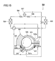
- FIG. 15 is a configuration diagram of the heat pump type heating device described in FIG. 3 of Patent Document 2.
- the heat pump heating apparatus 500 includes a rolling piston compressor 501, a condenser 503, an expansion mechanism 504, a gas-liquid separator 507, and an evaporator 509.
- the gas-phase refrigerant and vapor-liquid separator 507 from the evaporator 509 The separated intermediate-pressure gas-phase refrigerant is compressed by the compressor 501.
- a space between the cylinder 522 and the rotor 523 is divided into a main compression chamber 526 and a sub compression chamber 527 by vanes 525 and 535 attached to the cylinder 522 of the compressor 501.
- the main compression chamber 526 has a suction hole 526a and a discharge hole 526b.
- the sub compression chamber 527 has a suction hole 527a and a discharge hole 527b.
- the suction hole 526a is connected to the evaporator 509, and the suction hole 527a is connected to the gas-liquid separator 507.
- the discharge holes 526 b and the discharge holes 527 b are gathered together and connected to the condenser 503.
- JP 2006-112753 A Japanese Patent Publication No. 3-53532
- the present inventors examined in detail whether the heat pump type heating apparatus 500 described in Patent Document 2 can be put into practical use. As a result, the present inventors have found that the following technical problems exist in the compressor 501.
- the difference between the pressure applied to the front end surface 541 of the vane 540 and the pressure applied to the back surface 542 is mainly used.
- a force for pressing the vane 540 toward the piston 543 is generated.
- a pressure equal to the discharge pressure (high pressure) is applied to the back surface 542 of the vane 540.
- the vane 540 has an arcuate tip surface 541 in plan view, and the tip surface 541 is in contact with the piston 543.
- suction pressure (low pressure) from the suction hole 544 is always applied to the right side portion of the front end surface 541 when viewed from the contact point between the vane 540 and the piston 543.
- a pressure changing between the suction pressure (low pressure) and the discharge pressure (high pressure) is applied to the left side portion of the distal end surface 541.
- the suction pressure (low pressure) is always applied to the right side portion of the tip surface 541, so the pressure difference between the tip surface 541 and the back surface 542 is Sufficiently secured. Therefore, a sufficiently large pressing force always acts on the vane 540 toward the piston 543.
- the rolling piston compressor 501 described in Patent Document 2 two vanes are provided in one cylinder.
- the pressing force acting on the two vanes is verified in the same way as a rolling piston type compressor having only one vane.
- the suction pressure (low pressure) from the suction hole 526a is always applied to the half of the tip surface of the vane 525.
- the pressure in the sub compression chamber 527 is applied to the other half of the tip surface of the vane 525.
- the pressure in the sub-compression chamber 527 changes between the pressure (intermediate pressure) of the gas-phase refrigerant separated by the gas-liquid separator 507 and the discharge pressure (high pressure). Therefore, on the assumption that the rolling piston compressor 501 is a high-pressure shell compressor, a sufficiently large pressing force acts on the vane 525 toward the piston 523.
- the suction pressure from the suction hole 527a that is, the pressure of the gas-phase refrigerant separated by the gas-liquid separator 507 (intermediate pressure) is always applied to the half of the tip surface of the vane 535.
- the pressure in the main compression chamber 526 is applied to the other half of the tip surface of the vane 535.
- the pressure in the main compression chamber 526 varies between the suction pressure (low pressure) and the discharge pressure (high pressure). Therefore, the pressing force (minimum pressing force) acting on the vane 535 is smaller than the pressing force acting on the vane 525 and the pressing force acting on the vane 540 of the conventional rolling piston compressor.
- vane jump means a phenomenon in which the tip of the vane is separated from the piston. When vane jumps occur, the compressor efficiency may be significantly reduced.
- An object of the present invention is to prevent vane jumping of a rotary compressor that can be employed in injection technology.
- the present invention A cylinder, A piston disposed in the cylinder so as to form a space between itself and the cylinder; A shaft to which the piston is attached; A first vane attached to the cylinder at a first angular position along a rotational direction of the shaft and partitioning the space along a circumferential direction of the piston; A first compression chamber and a second compression chamber having a volume smaller than the volume of the first compression chamber are formed in the cylinder at a second angular position along the rotation direction of the shaft.
- a second vane further partitioning the space partitioned by the first vane along a circumferential direction of the piston, Provided is a rotary compressor in which the piston and the second vane are integrated or the piston and the second vane are combined.
- the rotary compressor of the present invention is A first suction hole for guiding the working fluid to be compressed in the first compression chamber to the first compression chamber; A first discharge hole for guiding the working fluid compressed in the first compression chamber from the first compression chamber to the outside of the first compression chamber; A second suction hole for guiding the working fluid to be compressed in the second compression chamber to the second compression chamber; A second discharge hole for guiding the working fluid compressed in the second compression chamber from the second compression chamber to the outside of the second compression chamber; A suction check valve provided in the second suction hole.
- the present invention provides: A rotary compressor according to the preferred embodiment; A radiator for cooling the working fluid compressed by the rotary compressor; An expansion mechanism for expanding the working fluid cooled by the radiator; A gas-liquid separator that separates the working fluid expanded by the expansion mechanism into a gaseous working fluid and a liquid working fluid; An evaporator for evaporating the liquid-phase working fluid separated by the gas-liquid separator; A suction flow path for guiding the working fluid flowing out of the evaporator to the first suction hole of the rotary compressor; An injection flow path for guiding the gas-phase working fluid separated by the gas-liquid separator to the second suction hole of the rotary compressor; A refrigeration cycle apparatus is provided.
- the piston and the second vane are integrated, or the piston and the second vane are combined.
- the refrigeration cycle apparatus using the rotary compressor of the present invention can enjoy a high injection effect.
- FIG. 2 The block diagram of the refrigerating-cycle apparatus which concerns on 1st Embodiment of this invention.
- FIG. 2 is a cross-sectional view taken along the line AA of the rotary compressor shown in FIG.
- Schematic plan view showing the structure to prevent vane jumping Schematic plan view showing another structure for preventing vane jumping
- Schematic plan view showing still another structure for preventing vane jumping Schematic plan view showing still another structure for preventing vane jumping
- Expanded sectional view of the suction check valve Side view and plan view of the valve body Side view and plan view of valve stop Perspective view of compression mechanism
- Schematic showing the operation of the rotary compressor for each rotation angle of the shaft PV diagram of the first compression chamber PV diagram of the second compression chamber PV diagram of the second compression chamber showing the compression work that can be reduced by injection Schematic showing the operation of the rotary compressor without the suction check valve PV diagram of the second compression chamber shown in FIG.
- FIG. 11A Schematic which shows the modification designed so that the angle which the 1st vane and the 2nd vane make may become an obtuse angle
- FIG. 11A Configuration diagram of a conventional heat pump heating system
- Cross-sectional view of a conventional rolling piston compressor having only one vane Schematic showing the problem when the second vane is not connected to the piston
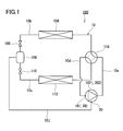
- FIG. 1 is a configuration diagram of a refrigeration cycle apparatus according to the present embodiment.
- the refrigeration cycle apparatus 100 includes a rotary compressor 102, a first heat exchanger 104, a first expansion mechanism 106, a gas-liquid separator 108, a second expansion mechanism 110, and a second heat exchanger 112. These components are annularly connected in the above order by the flow paths 10 a to 10 d so as to form the refrigerant circuit 10.
- the flow paths 10a to 10d are typically constituted by refrigerant pipes.
- the refrigerant circuit 10 is filled with a refrigerant such as hydrofluorocarbon or carbon dioxide as a working fluid.
- the refrigeration cycle apparatus 100 further includes an injection flow path 10j.
- the injection flow path 10j has one end connected to the gas-liquid separator 108 and the other end connected to the rotary compressor 102.
- the gas-phase refrigerant separated by the gas-liquid separator 108 is exchanged with the rotary compressor 102. Lead directly to.
- the injection flow path 10j is typically composed of a refrigerant pipe.
- a pressure reducing valve may be provided in the injection flow path 10j.
- An accumulator may be provided in the injection flow path 10j.
- the refrigerant circuit 10 is provided with a four-way valve 116 as a switching mechanism capable of switching the flow direction of the refrigerant.
- the four-way valve 116 is controlled as indicated by a solid line in FIG. 1, the refrigerant compressed by the rotary compressor 102 is supplied to the first heat exchanger 104.
- the first heat exchanger 104 functions as a radiator (condenser) that cools the refrigerant compressed by the rotary compressor 102.
- the second heat exchanger 112 functions as an evaporator that evaporates the liquid-phase refrigerant separated by the gas-liquid separator 108.
- the four-way valve 116 is controlled as shown by a broken line in FIG.
- the refrigerant compressed by the rotary compressor 102 is supplied to the second heat exchanger 112.
- the first heat exchanger 104 functions as an evaporator
- the second heat exchanger 112 functions as a radiator.
- the air conditioning apparatus employing the refrigeration cycle apparatus 100 can be provided with both functions of cooling and heating.
- the rotary compressor 102 is a device for compressing the refrigerant to a high temperature and a high pressure.
- the rotary compressor 102 has a first suction hole 19 (main suction hole) and a second suction hole 20 (injection suction hole).
- a flow path 10 d is connected to the first suction hole 19 so that the refrigerant flowing out from the first heat exchanger 104 or the second heat exchanger 112 is guided to the rotary compressor 102.
- the injection flow path 10j is connected to the second suction hole 20 so that the gas-phase refrigerant separated by the gas-liquid separator 108 is guided to the rotary compressor 102.
- the first heat exchanger 104 is typically composed of an air-refrigerant heat exchanger or a water-refrigerant heat exchanger.
- the second heat exchanger 112 is also typically composed of an air-refrigerant heat exchanger or a water-refrigerant heat exchanger.
- both the first heat exchanger 104 and the second heat exchanger 112 are configured with an air-refrigerant heat exchanger.
- the first heat exchanger 104 is configured with a water-refrigerant heat exchanger
- the second heat exchanger 112 is configured with an air-refrigerant heat exchanger.
- the first expansion mechanism 106 and the second expansion mechanism 110 are a refrigerant cooled by the first heat exchanger 104 (or the second heat exchanger 112) as a radiator or a liquid phase separated by the gas-liquid separator 108. It is a device for expanding the refrigerant.
- the first expansion mechanism 106 and the second expansion mechanism 110 are typically configured by expansion valves.
- a suitable expansion valve includes a valve whose opening degree can be changed, for example, an electric expansion valve.
- the first expansion mechanism 106 is provided on the flow path 10 b between the first heat exchanger 104 and the gas-liquid separator 108.
- the second expansion mechanism 110 is provided on the flow path 10 c between the gas-liquid separator 108 and the second heat exchanger 112.
- the expansion mechanisms 106 and 110 may each be composed of a positive displacement expander that can recover power from the refrigerant.
- the gas-liquid separator 108 separates the refrigerant expanded by the first expansion mechanism 106 or the second expansion mechanism 110 into a gas phase refrigerant and a liquid phase refrigerant.
- the gas-liquid separator 108 is provided with an inlet for the refrigerant expanded by the first expansion mechanism 106 or the second expansion mechanism 110, an outlet for the liquid phase refrigerant, and an outlet for the gas phase refrigerant.
- One end of the injection flow path 10j is connected to the outlet of the gas phase refrigerant.
- the refrigerant circuit 10 may be provided with other devices such as an accumulator and an internal heat exchanger.
- FIG. 2 is a longitudinal sectional view of the rotary compressor 102 used in the refrigeration cycle apparatus 100 shown in FIG.
- FIG. 3 is a cross-sectional view taken along line AA of the rotary compressor 102 shown in FIG.
- the rotary compressor 102 includes a sealed container 1, a motor 2, a compression mechanism 3, and a shaft 4.
- the compression mechanism 3 is disposed in the lower part in the sealed container 1.
- the motor 2 is disposed on the compression mechanism 3 in the sealed container 1.
- the compression mechanism 3 and the motor 2 are connected by the shaft 4.
- a terminal 21 for supplying electric power to the motor 2 is provided on the top of the sealed container 1.
- An oil sump 22 for holding lubricating oil is formed at the bottom of the sealed container 1.
- the motor 2 includes a stator 17 and a rotor 18.
- the stator 17 is fixed to the inner wall of the sealed container 1.
- the rotor 18 is fixed to the shaft 4 and rotates together with the shaft 4.
- a discharge pipe 11 is provided on the top of the sealed container 1.
- the discharge pipe 11 penetrates the upper part of the sealed container 1 and opens toward the internal space 13 of the sealed container 1.
- the discharge pipe 11 serves as a discharge flow path that guides the refrigerant compressed by the compression mechanism 3 to the outside of the sealed container 1. That is, the discharge pipe 11 constitutes a part of the flow path 10a shown in FIG.
- the internal space 13 of the sealed container 1 is filled with the compressed refrigerant.
- the rotary compressor 102 is a high-pressure shell type compressor. According to the high-pressure shell-type rotary compressor 102, the motor 2 can be cooled with the refrigerant, so that improvement in motor efficiency can be expected. When the refrigerant is heated by the motor 2, the heating capacity of the refrigeration cycle apparatus 100 is also improved.
- the compression mechanism 3 is moved by the motor 2 so as to compress the refrigerant. 2 and 3, the compression mechanism 3 includes a cylinder 5, a main bearing 6, a sub bearing 7, a piston 8, a muffler 9, a first vane 32, a second vane 33, a first discharge valve 43, a second It has a discharge valve 44 and a suction check valve 50.
- the suction check valve 50 is provided only in the second suction hole 20 out of the first suction hole 19 and the second suction hole 20.
- the shaft 4 has an eccentric part 4a protruding outward in the radial direction.
- the piston 8 is disposed inside the cylinder 5. Inside the cylinder 5, a piston 8 is attached to the eccentric part 4 a of the shaft 4.
- a first vane groove 34 and a second vane groove 35 are formed in the cylinder 5.
- the first vane groove 34 is formed at a first angular position along the rotation direction of the shaft 4.
- the second vane groove 35 is formed at a second angular position along the rotation direction of the shaft 4.
- first vane 32 (blade) having a tip in contact with the outer peripheral surface of the piston 8 is attached so as to be slidable.
- the first vane 32 partitions the space between the cylinder 5 and the piston 8 along the circumferential direction of the piston 8.
- a second vane 33 (blade) is attached to the second vane groove 35 so as to be slidable.
- the second vane 33 further partitions the space between the cylinder 5 and the piston 8 along the circumferential direction of the piston 8.
- a first spring 36 that pushes the first vane 32 toward the center of the shaft 4 is disposed behind the first vane 32.
- the rear portion of the first vane groove 34 communicates with the internal space 13 of the sealed container 1. Accordingly, the pressure in the internal space 13 of the sealed container 1 is applied to the back surface of the first vane 32.
- the second vane 33 is coupled to the piston 8. For this reason, no spring is disposed behind the second vane 33. However, a spring may be disposed behind the second vane 33.
- the second vane groove 35 also communicates with the internal space 13 of the sealed container 1. Lubricating oil stored in the oil reservoir 22 is supplied to the first vane groove 34 and the second vane groove 35.
- the position of the first vane 32 and the first vane groove 34 is defined as a position of “0 degree (first angle)” along the rotation direction of the shaft 4.
- the rotation angle of the shaft 4 at the moment when the first vane 32 is pushed into the first vane groove 34 to the maximum by the piston 8 is defined as “0 degree”.
- the rotation angle of the shaft 4 at the moment when the second vane 33 is pushed into the second vane groove 35 to the maximum by the piston 8 corresponds to the “second angle”.
- the angle ⁇ (degree) from the first angular position where the first vane 32 is disposed to the second angular position where the second vane 33 is disposed is, for example, 270 with respect to the rotation direction of the shaft 4.
- the angle (360- ⁇ ) formed by the first vane 32 and the second vane 33 is in the range of 10 to 90 degrees. If the angle ⁇ is 270 degrees or more, the amount of refrigerant flowing back from the first compression chamber 25 to the first suction pipe 14 through the first suction hole 19 in the suction stroke of the first compression chamber 25 is sufficiently small. Therefore, it is not necessary to provide a check valve in the first suction hole 19.
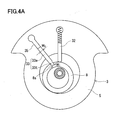
- the piston 8 is provided with a concave portion 8s
- the second vane 33 is provided with a convex portion 33t.
- the convex portion 33t of the second vane 33 is fitted into the concave portion 8s of the piston 8 so that the piston 8 and the second vane 33 are coupled. Since the piston 8 and the second vane 33 are coupled, the second vane 33 always moves following the piston 8. Therefore, there is essentially no vane skip problem related to the second vane 33.
- the second vane 33 is composed of a slide portion 33a that is housed in the second vane groove 35 and a convex portion 33t that is located at the tip of the slide portion 33a.
- the convex portion 33t has a circular shape in plan view.
- the concave portion 8s of the piston 8 for fitting the convex portion 33t also has a circular shape in plan view.
- the convex portion 33t and the concave portion 8s can relatively rotate while maintaining the coupling between the second vane 33 and the piston 8.
- the piston 8 rotates, the second vane 33 slides in the second vane groove 35.
- the convex portion 33 t of the second vane 33 rotates in the concave portion 8 s of the piston 8.
- the width W 1 of the convex portion 33t of the second vane 33 is narrower than the width W 2 of the sliding portion 33a. According to such a configuration, the finish polishing of the slide portion 33a is easy, so the manufacturing cost of the second vane 33 can be reduced.
- the “width of the vane” means a dimension in a direction orthogonal to the axial direction of the shaft 4 and the longitudinal direction of the vane.
- the structure that can prevent vane jumping is not limited to the structure shown in FIG. 4A. Hereinafter, some specific examples will be described.
- the piston 8 is provided with a convex portion 8t
- the second vane 33 is provided with a concave portion 33s.
- the convex portion 8t of the piston 8 is fitted into the concave portion 33s of the second vane 33 so that the piston 8 and the second vane 33 are coupled. That is, the structure for connecting the vane to the piston is not particularly limited.
- the piston 8 and the first vane 32 are constituted by an integrally formed swing piston 56. That is, the first vane 32 is integrated with the piston 8.
- a bush 57 (first bush) is disposed in the first vane groove 34 (bush groove).
- the bush 57 is composed of two members having a substantially semi-cylindrical shape.
- the outer peripheral surface of the semi-cylindrical member includes a flat surface and an arc surface.
- the plane of the semi-cylindrical member faces the side surface of the first vane 32, and the arc surface of the semi-cylindrical member faces the arc surface of the first vane groove 34.
- the first vane 32 is slidably sandwiched between the bushes 57, and the bush 57 itself can slide relative to the cylinder 5.
- the first vane 32 moves back and forth in the first vane groove 34 while changing its posture little by little.
- the first vane 32 is swingably disposed in the first vane groove 34 of the cylinder 5 via the bush 57.
- the bush 57 can also rotate (swing) in the first vane groove 34.
- the second vane 33 is coupled to the piston 8. Specifically, as described with reference to FIG. 4A, the convex portion 33 t of the second vane 33 is fitted in the concave portion 8 s of the piston 8.
- a bush 58 (second bush) for holding the second vane 33 is provided at the second angular position so that the second vane 33 can swing as the piston 8 rotates.
- the operation of the bush 58 disposed in the second vane groove 35 is the same as the operation of the bush 57 disposed in the first vane groove 34.
- the convex portion 33 t of the second vane 33 and the concave portion 8 s of the piston 8 can be relatively rotated while maintaining the coupling between the second vane 33 and the piston 8.
- the second vane 33 operates in the same manner as the first vane 32 except for whether it is coupled to the piston 8 or integrated.
- the piston 8 is further provided with another concave portion 8c, and the first vane 32 is provided with a convex portion 32t.
- the convex portion 32 t of the first vane 32 is fitted in the other concave portion 8 c of the piston 8.
- a bush 57 (first bush) that holds the first vane 32 is provided at the first angular position so that the first vane 32 can swing as the piston 8 rotates.
- a bush 57 is disposed in the first vane groove 34.
- the positional relationship between the convex part and the concave part is not limited. That is, as described with reference to FIG. 4B, the piston 8 may be provided with a convex portion, and the second vane 33 may be provided with a concave portion. Furthermore, the piston 8 may be provided with another convex portion, and the first vane 32 may be provided with a concave portion. In this case, the other convex portion of the piston 8 can be fitted into the concave portion of the first vane 32.
- the second vane 33 may be configured to swing, or both the first vane 32 and the second vane 33 may be configured to swing.
- the first bush 57 that holds the first vane 32 at the first angular position is provided so that at least one selected from the first vane 32 and the second vane 33 can swing as the piston 8 rotates.
- a second bush 58 (see FIG. 4C) for holding the second vane 33 at the second angular position may be provided.
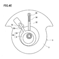
- the piston 8 and the second vane 33 are constituted by an integrally formed swing piston 59.
- the structure of the first vane 32 is not particularly limited.
- the first vane 32 has the same structure as that used in a general rolling piston compressor. That is, the first vane 32 is not coupled to the piston 8 and is not integrated with the piston 8.
- the piston 8 and the second vane 33 are constituted by the swing piston 59.
- the swing piston 59 is provided with a concave portion 8 c and the first vane 32 is provided with a convex portion 32 t.
- the convex portion 32t of the first vane 32 is fitted into the concave portion 8c of the swing piston 59 so that the swing piston 59 and the first vane 32 are coupled.
- a bush 57 that holds the first vane 32 is provided at the first angular position so that the first vane 32 can swing as the piston 8 rotates.
- the swing piston 59 may be provided with a convex portion, and the first vane 32 may be provided with a concave portion.
- the convex portion of the swing piston 59 can be fitted into the concave portion of the first vane 32.
- the temperature of a specific portion of the piston 8 is slightly lower than the temperature of the remaining portion. If the temperature of the specific part is lower than the temperature of the remaining part, the refrigerant sucked into the second compression chamber 26 is difficult to receive heat from the piston 8. Since the refrigerant sucked into the second compression chamber 26 is difficult to receive heat from the piston 8, it is possible to suppress a decrease in volume efficiency of the second compression chamber 26 due to expansion of the sucked refrigerant.
- the main bearing 6 and the sub bearing 7 are respectively arranged on the upper side and the lower side of the cylinder 5 so as to close the cylinder 5.
- the muffler 9 is provided above the main bearing 6 and covers the first discharge valve 43 and the second discharge valve 44.
- the muffler 9 is formed with a discharge hole 9 a for guiding the compressed refrigerant to the internal space 13 of the sealed container 1.
- the shaft 4 passes through the center portion of the muffler 9 and is rotatably supported by the main bearing 6 and the sub bearing 7.
- the first suction hole 19 and the second suction hole 20 are formed in the cylinder 5.
- the first suction hole 19 guides the refrigerant to be compressed in the first compression chamber 25 to the first compression chamber 25.
- the second suction hole 20 guides the refrigerant to be compressed in the second compression chamber 26 to the second compression chamber 26.
- the first suction hole 19 and the second suction hole 20 may be formed in the main bearing 6 or the sub bearing 7, respectively.
- the second suction hole 20 has an opening area smaller than the opening area of the first suction hole 19.
- the opening areas S 1 and S 2 are, for example, 1.1 ⁇ (S 1 / S 2 ) ⁇ 30.
- “Dead volume” means a volume that does not function as a working chamber. In general, large dead volumes are not preferred for positive displacement fluid machines.
- a first suction pipe 14 main suction pipe
- a second suction pipe 16 injection suction pipe
- the first suction pipe 14 is fitted into the cylinder 5 through the trunk of the sealed container 1 so that the refrigerant can be supplied to the first suction hole 19.
- the first suction pipe 14 constitutes a part of the flow path 10d shown in FIG.
- the second suction pipe 16 is fitted into the cylinder 5 through the trunk portion of the sealed container 1 so that the refrigerant can be supplied to the second suction hole 20.
- the second suction pipe 16 constitutes a part of the injection flow path 10j shown in FIG.
- the compression mechanism 3 is further provided with a first discharge hole 40 (main discharge hole) and a second discharge hole 41 (injection discharge hole).
- the first discharge hole 40 and the second discharge hole 41 are respectively formed in the main bearing 6 so as to penetrate the main bearing 6 in the axial direction of the shaft 4.
- the first discharge hole 40 guides the refrigerant compressed in the first compression chamber 25 from the first compression chamber 25 to the outside of the first compression chamber 25 (in the present embodiment, the internal space of the muffler 9).
- the second discharge hole 41 guides the refrigerant compressed in the second compression chamber 26 from the second compression chamber 26 to the outside of the second compression chamber 26 (in this embodiment, the internal space of the muffler 9).
- a first discharge valve 43 and a second discharge valve 44 are provided in the first discharge hole 40 and the second discharge hole 41, respectively.
- the first discharge valve 43 opens.
- the second discharge valve 44 is opened.
- the muffler 9 serves as a discharge flow path that connects each of the first discharge hole 40 and the second discharge hole 41 and the internal space 13 of the sealed container 1.
- the refrigerant guided to the outside of the first compression chamber 25 through the first discharge hole 40 and the refrigerant guided to the outside of the second compression chamber 26 through the second discharge hole 41 merge inside the muffler 9.
- the merged refrigerant flows into the discharge pipe 11 via the internal space 13 of the sealed container 1.
- a motor 2 is arranged in the sealed container 1 so as to be positioned on the refrigerant flow path from the muffler 9 to the discharge pipe 11. According to such a configuration, the cooling of the motor 2 by the refrigerant and the heating of the refrigerant by the heat of the motor 2 can be performed efficiently.
- the second discharge hole 41 has an opening area smaller than the opening area of the first discharge hole 40.
- the opening areas S 3 and S 4 are, for example, 1.1 ⁇ (S 3 / S 4 ) ⁇ 15. Meet.
- each suction hole and each discharge hole should be appropriately determined in consideration of the flow rate of the refrigerant passing through them. More specifically, it should be determined in consideration of the balance between dead volume and pressure loss.
- the rotary compressor 102 of this embodiment includes not only the discharge valves 43 and 44 but also a suction check valve 50 provided in the second suction hole 20 for the reason described below.
- a suction check valve 50 provided in the second suction hole 20 for the reason described below.
- the suction check valve 50 includes a valve body 51 and a valve stop 52.
- a shallow groove 5g having a strip shape in plan view is formed on the upper surface 5p of the cylinder 5, and a valve body 51 and a valve stopper 52 are mounted in the groove 5g.
- the groove 5g extends outward in the radial direction of the cylinder 5 and communicates with the second compression chamber 26.
- the second suction hole 20 opens at the bottom of the groove 5g.
- the second suction hole 20 is formed of a bottomed hole formed in the cylinder 5, and the bottomed hole opens at the bottom of the groove 5g.
- a suction pipe 16 is connected to the suction flow path 5f.
- the valve body 51 has a back surface 51q that closes the second suction hole 20, and a surface 51p that is exposed to the atmosphere in the second compression chamber 26 when the second suction hole 20 is closed.
- a movable range of the valve main body 51 of the suction check valve 50 is set in the second compression chamber 26.
- the valve body 51 has a thin plate shape as a whole, and is typically composed of a thin metal plate (reed valve).
- the valve stop 52 has a support surface 52q that restricts the amount of displacement of the valve body 51 in the thickness direction when the second suction hole 20 is opened.
- the support surface 52q forms a gentle curved surface so that the thickness of the valve stop 52 decreases as it approaches the second compression chamber 26. That is, the valve stop 52 has a shoe-like shape as a whole.
- the distal end surface 52 t of the valve stop 52 has an arc shape having the same radius of curvature as the inner diameter of the cylinder 5.
- the valve body 51 is arranged in the groove 5g so that the second suction hole 20 can be opened and closed.
- the valve stopper 52 is disposed in the groove 5g so that the support surface 52q is exposed to the atmosphere in the second compression chamber 26 when the valve body 51 closes the second suction hole 20.
- the valve main body 51 and the valve stopper 52 are fixed to the cylinder 5 by a fastener 54 such as a bolt.
- the rear end portion of the valve main body 51 is sandwiched between the valve stopper 52 and the groove 5g and cannot move, but the front end portion of the valve main body 51 is not fixed and swings.
- the total thickness of the valve body 51 and the valve stop 52 is approximately equal to the depth of the groove 5g.
- the position of the upper surface 52p of the valve stop 52 coincides with the position of the upper surface of the cylinder 5 in the thickness direction of the cylinder 5.
- the valve body 51 has a wide portion 55 for opening and closing the second suction hole 20.
- the maximum width W 1 of the wide portion 55 is wider than the width W 2 of the tip of the valve stop 52, in other words, the width of the groove 5 g at the position facing the cylinder 5.
- the wide portion 55 can suppress an increase in dead volume while securing a seal width for closing the second suction hole 20.
- the depth of the groove 5g is smaller than half of the thickness of the cylinder 5, for example. Most of the groove 5g is filled with a valve stop 52. A very small part of the groove 5g is left as a movable range of the valve body 51.
- the suction check valve 50 operates as follows with the rotation of the shaft 5.
- the valve body 51 When the pressure in the second compression chamber 26 falls below the pressure in the suction flow path 5f and the second suction pipe 16, the valve body 51 is displaced into a shape along the support surface 52q of the valve stop 52. In other words, the valve body 51 is pushed up. Thereby, the second suction hole 20 and the second compression chamber 26 communicate with each other, and the refrigerant is supplied to the second compression chamber 26 through the second suction hole 20.
- the valve body 51 returns to the original flat shape. As a result, the second suction hole 20 is closed. Therefore, it is possible to prevent the refrigerant sucked into the second compression chamber 26 from flowing back to the suction flow path 5f and the second suction pipe 16 through the second suction hole 20.
- the suction check valve 50 of the present embodiment an increase in dead volume due to the provision of the check valve in the suction hole can be suppressed by the above-described some characteristic structures. That is, the suction check valve 50 contributes to achievement of high compressor efficiency. Therefore, the refrigeration cycle apparatus 100 using the rotary compressor 102 of the present embodiment has a high COP.
- the second suction hole 20 may be formed in the main bearing 6 or the sub-bearing 7.
- the suction check valve 50 having the structure described with reference to FIG. 5 and the like can be provided in the main bearing 6 or the sub bearing 7.
- a member (closing member) for closing the cylinder 5 may be provided between the main bearing 6 (or the auxiliary bearing 7) and the cylinder 5, and the suction check valve 50 may be provided on this member.
- the angle in FIG. 8 represents the rotation angle of the shaft 4. Note that the angles shown in FIG. 8 are merely examples, and each stroke does not necessarily start or end at the angles shown in FIG.
- the process of sucking the refrigerant into the first compression chamber 25 is performed from when the shaft 4 occupies a rotation angle of 0 degrees to when it occupies a rotation angle of approximately 360 degrees.
- the refrigerant sucked into the first compression chamber 25 is compressed as the shaft 4 rotates.
- the compression stroke continues until the pressure in the first compression chamber 25 exceeds the pressure in the internal space 13 of the sealed container 1.
- the compression stroke is performed from when the shaft 4 occupies a rotation angle of 360 degrees to when it has a rotation angle of 540 degrees.
- the process of discharging the compressed refrigerant out of the first compression chamber 25 is performed until the contact point between the cylinder 5 and the piston 8 passes through the first discharge hole 40.
- the discharge stroke is performed from when the shaft 4 occupies a rotation angle of 540 degrees to when it occupies a rotation angle of (630 + ⁇ ) degrees.
- “ ⁇ ” represents an angle from an angular position of 270 degrees to a second angular position where the second vane 33 is disposed.
- the process of sucking the refrigerant into the second compression chamber 26 is performed from when the shaft 4 occupies a rotation angle of (270 + ⁇ ) degrees to when it occupies a rotation angle of (495 + ⁇ / 2) degrees.
- (495 + ⁇ / 2) degrees is the rotation angle of the shaft 4 when the second compression chamber 26 has the maximum volume.
- the refrigerant sucked into the second compression chamber 26 is compressed as the shaft 4 rotates.
- the compression stroke continues until the pressure in the second compression chamber 26 exceeds the pressure in the internal space 13 of the sealed container 1.
- the compression stroke is performed from when the shaft 4 occupies a rotation angle of (495 + ⁇ / 2) degrees to when it occupies a rotation angle of 630 degrees.
- the process of discharging the compressed refrigerant out of the second compression chamber 26 is performed until the contact point between the cylinder 5 and the piston 8 passes through the second discharge hole 41.
- the discharge stroke is performed from when the shaft 4 occupies a rotation angle of 630 degrees to when it occupies a rotation angle of 720 degrees.
- FIG. 9A and 9B show PV diagrams of the first compression chamber 25 and the second compression chamber 26, respectively.
- the suction stroke in the first compression chamber 25 is represented by a change from point A to point B.
- the volume of the first compression chamber 25 reaches the maximum value at the point B, but since the check valve is not provided in the first compression chamber 25, a small amount of refrigerant is first added between the point B and the point C. It flows backward from the compression chamber 25 to the first suction hole 19. Therefore, the actual suction volume (confined volume) of the first compression chamber 25 is specified by the volume at point C.
- the compression stroke is represented by a change from point C to point D.
- the discharge stroke is represented by a change from point D to point E.
- the suction stroke in the second compression chamber 26 is represented by a change from point F to point G. Due to the function of the suction check valve 50, the reverse flow rate of the refrigerant from the second compression chamber 26 to the second suction hole 20 is substantially zero. Therefore, the maximum volume of the second compression chamber 26 matches the actual suction volume.
- the compression stroke is represented by a change from point G to point H.
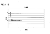
- the discharge stroke is represented by a change from point H to point I. Since the second compression chamber 26 sucks and compresses the gas refrigerant having the intermediate pressure, the compression work corresponding to the area of the hatched area can be reduced as shown in FIG. Thereby, the efficiency of the refrigeration cycle apparatus 100 is improved.
- 9B and 10 are PV diagrams when the dead volume due to the suction check valve 50 is assumed to be zero.
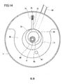
- FIG. 11A is a schematic diagram showing the operation of a rotary compressor that does not have a suction check valve.
- the angle between the two vanes is 90 degrees.
- the compression chamber 536 and the suction hole 537 correspond to the second compression chamber 26 and the second suction hole 20 of this embodiment, respectively.
- the compression chamber 536 has a maximum volume.
- the refrigerant flows backward from the compression chamber 536 to the suction hole 537 (a reverse fashion).
- FIGS. 9A, 9B, 10 and 11B are drawn on the same scale.
- FIG. 11A and FIG. 11B are diagrams for explaining problems when there is no suction check valve, and do not constitute the prior art of the present invention.
- the positional relationship between the first vane 32 and the second vane 33 will be described.
- the positional relationship between the two is also deeply related to the opening / closing timing of the suction check valve 50.
- the opening / closing timing of the suction check valve 50 also depends on the type of refrigerant, the use of the refrigeration cycle apparatus 100, and the like.
- the angle ⁇ from the first angular position (0 degree) at which the first vane 32 is disposed to the second angular position at which the second vane 33 is disposed is 270 with respect to the rotation direction of the shaft 4. It is set to more than degrees.
- the angle ⁇ should be appropriately set according to the flow rate of the refrigerant to be compressed in the first compression chamber 25 and the flow rate of the refrigerant to be compressed in the second compression chamber 26.
- angle ⁇ becomes smaller, the amount of refrigerant that flows back from the first compression chamber 25 to the first suction hole 19 increases.
- An appropriate range of the angle ⁇ is, for example, 270 ⁇ ⁇ ⁇ 350.
- the optimum angle ⁇ varies depending on the use of the refrigeration cycle apparatus 100. As shown in FIG. 12, a configuration in which the angle ⁇ is less than 270 degrees is also conceivable. As the angle ⁇ decreases, the amount of refrigerant that flows back from the first compression chamber 25 to the first suction hole 19 increases. In order to prevent the reverse flow of the refrigerant from the first compression chamber 25 to the first suction hole 19, a suction check valve can also be provided in the first suction hole 19.
- the suction check valve 50 is configured such that the refrigerant sucked into the second compression chamber 26 passes through the second suction hole 20 during the period specified by (i), (ii), or (iii). Backflow out of the compression chamber 26 is prevented.
- the suction check valve 50 prevents backflow from the time when the second compression chamber 26 reaches the maximum volume to the time when the second compression chamber 26 reaches the minimum volume ( ⁇ 0).
- the suction check valve 50 flows backward from the time when the second compression chamber 26 reaches the maximum volume until the time when the compressed refrigerant starts to be discharged out of the second compression chamber 26 through the second discharge hole 41. To prevent.
- the suction check valve 50 extends from the time when the second compression chamber 26 reaches the maximum volume to the time when the contact point between the cylinder 5 and the piston 8 passes through the second suction hole 20 as the shaft 4 rotates. To prevent backflow.
- the suction check valve 50 moves (i).
- the suction check valve 50 moves (ii) or (iii).
- the suction check valve 50 greatly contributes to the improvement of the compressor efficiency. However, from the viewpoint of preventing vane jumping, the suction check valve 50 has an adverse effect.
- FIG. 15 consider a case where an intake check valve is not provided.
- the suction check valve is not provided, at the moment when the piston 523 pushes the vane 535 into the vane groove to the state shown in FIG. 15, the discharge pressure (high pressure) of the compression chamber 526 is placed on the half of the front end surface of the vane 535. Is added.
- the suction pressure (intermediate pressure) of the suction hole 527a is applied to the other half of the tip surface of the vane 535. Therefore, assuming that the rolling piston compressor 501 is a high-pressure shell compressor, the vane 535 is always pressed to a certain degree based on the difference between the pressure applied to the tip surface and the pressure applied to the back surface. Power works.
- FIG. 17 a case is considered in which a suction check valve is provided in the second suction hole, but the second vane is not coupled to the piston.
- the discharge pressure (high pressure) of the first compression chamber 554 is applied to half of the tip surface of the second vane 552.
- the pressure of the second compression chamber 556 is applied to the other half of the tip surface of the second vane 552.
- the pressure in the second compression chamber 556 is equal to or close to the discharge pressure (high pressure) in the state shown in FIG. That is, in the state shown in FIG.
- the pressing force acting on the second vane 552 is almost zero based on the difference between the pressure applied to the tip surface and the pressure applied to the back surface, and only the pressing force by the spring 553 is applied.
- Second vane 552 In this state, when the piston 558 passes the top dead center of the second vane 552, an outward inertial force is acting on the second vane 552, so the second vane 552 cannot follow the piston 558, and as a result, Vane jump may occur.
- FIG. 17 is a figure for demonstrating a problem when the 2nd vane is not couple
- FIG. 13 is a longitudinal sectional view of a rotary compressor according to a modification.
- the rotary compressor 202 has a structure in which components such as a cylinder are added to the rotary compressor 102 shown in FIG.
- the compression mechanism 3, the cylinder 5, the piston 8, and the eccentric portion 4a shown in FIG. 2 are defined as the first compression mechanism 3, the first cylinder 5, the first piston 8, and the first eccentric portion 4a, respectively.
- the detailed structure of the first compression mechanism 3 is as described with reference to FIGS.
- the rotary compressor 202 includes a second compression mechanism 30 in addition to the first compression mechanism 3.
- the second compression mechanism 30 includes a second cylinder 65, an intermediate plate 66, a second piston 68, a sub bearing 67, a muffler 70, a third vane 72, a third suction hole 69, and a third discharge hole 73.
- the second cylinder 65 is disposed concentrically with respect to the first cylinder 5 and is separated from the first cylinder 5 by an intermediate plate 66.
- the shaft 4 has a second eccentric portion 4b protruding outward in the radial direction.
- the second piston 68 is disposed inside the second cylinder 65. Inside the second cylinder 65, the second piston 68 is attached to the second eccentric portion 4 b of the shaft 4.
- the intermediate plate 66 is disposed between the first cylinder 5 and the second cylinder 65.
- a vane groove 74 is formed in the second cylinder 65.
- a third vane 72 (blade) having a tip in contact with the outer peripheral surface of the second piston 68 is attached to the vane groove 74 so as to be slidable.
- the third vane 72 partitions the space between the second cylinder 65 and the second piston 68 along the circumferential direction of the second piston 68.
- the third compression chamber 71 is formed inside the second cylinder 65.
- the second piston 68 and the third vane 72 may be configured as a single part, a so-called swing piston. Further, the third vane 72 may be coupled to the second piston 68.
- a third spring 76 that pushes the third vane 72 toward the center of the shaft 4 is disposed behind the third vane 72.
- the third suction hole 69 guides the refrigerant to be compressed in the third compression chamber 71 to the third compression chamber 71.
- a third suction pipe 64 is connected to the third suction hole 69.
- the third discharge hole 73 passes through the auxiliary bearing 67 and opens toward the inner space of the muffler 70.
- the refrigerant compressed in the third compression chamber 71 passes through the third discharge hole 73 and is guided from the third compression chamber 71 to the outside of the third compression chamber 71, specifically, to the internal space of the muffler 70.
- the inside of the sealed container 1 is passed from the inner space of the muffler 70 through the flow path 63 that passes through the main bearing 6, the first cylinder 5, the middle plate 66, the second cylinder 65, and the auxiliary bearing 67 in the axial direction of the shaft 4.
- the refrigerant is guided to the space 13.
- the channel 63 may open toward the internal space 13 of the sealed container 1 or may open toward the internal space of the muffler 9.
- the second compression mechanism 30 has the same structure as the compression mechanism of a normal rolling piston compressor having only one vane.
- the second piston 68 and the third vane 72 may be integrated. Alternatively, the second piston 68 and the third vane 72 may be coupled. That is, the structure described with reference to FIGS. 4A to 4F can be applied to the second piston 68 and the third vane 72. Although the problem of vane jumping is unlikely to occur with respect to the third vane 72, it is possible to expect a cost reduction effect by sharing parts between the first compression mechanism 3 and the second compression mechanism 30.
- the height, inner diameter, and outer diameter of the second cylinder 65 are equal to the height, inner diameter, and outer diameter of the first cylinder 5, respectively.
- the outer diameter of the first piston 8 is equal to the outer diameter of the second piston 68. Since only the third compression chamber 71 is formed inside the second cylinder 65, the first compression chamber 25 has a volume smaller than the volume of the third compression chamber 71. That is, by sharing parts between the first compression mechanism 3 and the second compression mechanism 30, it is possible to reduce costs and improve assembly ease.
- the first compression mechanism 3 is disposed on the upper side and the second compression mechanism 30 is disposed on the lower side with respect to the axial direction of the shaft 4.
- the refrigerant compressed by the first compression mechanism 3 is guided to the internal space of the muffler 9 through the discharge holes 40 and 41 provided in the main bearing 6.
- the first compression mechanism 3 has two discharge holes 40 and 41. Therefore, it is desirable to shorten the distance from the discharge holes 40 and 41 to the internal space 13 of the sealed container 1 as much as possible, thereby reducing the pressure loss of the refrigerant in the discharge holes 40 and 41 as much as possible. From this viewpoint, it is preferable that the first compression mechanism 3 is disposed on the upper side in the axial direction.
- the first compression mechanism 3 may be disposed on the lower side in the axial direction.
- the reason is as follows. The closer to the motor 2, the higher the temperature inside the sealed container 1. That is, during the operation of the rotary compressor 202, the main bearing 6 has a temperature higher than the temperatures of the auxiliary bearing 67 and the muffler 70. Therefore, when the first compression mechanism 3 is disposed on the upper side and the second compression mechanism 30 is disposed on the lower side, the refrigerant to be guided to the second compression chamber 26 is easily heated. Then, since the mass flow rate of the refrigerant to be compressed in the second compression chamber 26 is reduced, the effect by the injection is also reduced. In order to obtain a higher injection effect, the first compression mechanism 3 having the second compression chamber 26 may be disposed on the lower side, and the second compression mechanism 30 may be disposed on the upper side.
- the angular difference between the protruding direction of the first eccentric portion 4a and the protruding direction of the second eccentric portion 4b is 180 degrees.
- the phase difference between the first piston 8 and the second piston 68 is 180 degrees with respect to the rotation direction of the shaft 4.
- the timing of the top dead center of the first piston 8 is shifted by 180 degrees from the timing of the top dead center of the second piston 68. According to such a configuration, vibration generated based on the rotation of the first piston 8 can be canceled out by the rotation of the second piston 68.
- the compression stroke of the first compression chamber 25 and the compression stroke of the third compression chamber 71 are substantially alternately performed, and the discharge stroke of the first compression chamber 25 and the discharge stroke of the third compression chamber 71 are substantially alternately alternated. Done. Therefore, the torque fluctuation of the shaft 4 can be reduced, which is advantageous in reducing motor loss and mechanical loss. In addition, vibration and noise of the rotary compressor 202 can be reduced.
- the “timing of the top dead center of the piston” means the timing at which the vane is pushed into the vane groove to the maximum by the piston.
- the refrigeration cycle apparatus 100 includes a suction flow path 10d that guides the refrigerant flowing out from the first heat exchanger 104 or the second heat exchanger 112 as an evaporator to the first suction hole 19 of the rotary compressor 202. As shown in FIG. 13, the refrigerant flowing out from the first heat exchanger 104 or the second heat exchanger 112 is sucked so as to be guided to both the first suction hole 19 and the third suction hole 69 of the rotary compressor 202.
- the flow path 10 d includes a branch portion 14 that extends toward the first suction hole 19 and a branch portion 64 that extends toward the third suction hole 69.
- the first suction pipe 14 constitutes the branch portion 14
- the third suction pipe 64 constitutes the branch portion 64. According to such a configuration, the refrigerant can be smoothly guided to the first compression chamber 25 and the third compression chamber 71.
- the suction channel 10 d may be branched inside the sealed container 1.
- the refrigeration cycle apparatus of the present invention can be used for a water heater, a hot water heater, an air conditioner, and the like.
Landscapes
- Engineering & Computer Science (AREA)
- Mechanical Engineering (AREA)
- General Engineering & Computer Science (AREA)
- Physics & Mathematics (AREA)
- Thermal Sciences (AREA)
- Applications Or Details Of Rotary Compressors (AREA)
Priority Applications (4)
| Application Number | Priority Date | Filing Date | Title |
|---|---|---|---|
| JP2012523767A JP5631399B2 (ja) | 2010-07-08 | 2011-07-06 | ロータリ圧縮機及び冷凍サイクル装置 |
| US13/497,462 US8985985B2 (en) | 2010-07-08 | 2011-07-06 | Rotary compressor and refrigeration cycle apparatus |
| EP11803330.7A EP2592277B1 (en) | 2010-07-08 | 2011-07-06 | Rotary compressor and refrigeration cycle apparatus |
| CN201180003944.9A CN102575674B (zh) | 2010-07-08 | 2011-07-06 | 回转式压缩机及制冷循环装置 |
Applications Claiming Priority (2)
| Application Number | Priority Date | Filing Date | Title |
|---|---|---|---|
| JP2010-156037 | 2010-07-08 | ||
| JP2010156037 | 2010-07-08 |
Publications (1)
| Publication Number | Publication Date |
|---|---|
| WO2012004993A1 true WO2012004993A1 (ja) | 2012-01-12 |
Family
ID=45440982
Family Applications (1)
| Application Number | Title | Priority Date | Filing Date |
|---|---|---|---|
| PCT/JP2011/003870 WO2012004993A1 (ja) | 2010-07-08 | 2011-07-06 | ロータリ圧縮機及び冷凍サイクル装置 |
Country Status (5)
| Country | Link |
|---|---|
| US (1) | US8985985B2 (zh) |
| EP (1) | EP2592277B1 (zh) |
| JP (1) | JP5631399B2 (zh) |
| CN (1) | CN102575674B (zh) |
| WO (1) | WO2012004993A1 (zh) |
Cited By (1)
| Publication number | Priority date | Publication date | Assignee | Title |
|---|---|---|---|---|
| KR20150099685A (ko) * | 2013-09-30 | 2015-09-01 | 광동 메이지 컴프레셔 컴퍼니 리미티드 | 냉매 충전형 회전 압축기 |
Families Citing this family (14)
| Publication number | Priority date | Publication date | Assignee | Title |
|---|---|---|---|---|
| US9383123B2 (en) * | 2011-05-10 | 2016-07-05 | Panasonic Intellectual Property Management Co., Ltd. | Refrigeration cycle device capable of efficiently varying capacity providing a first and a second compressing mechanism disposed in a hermetic container |
| EP3078859B1 (en) * | 2013-12-05 | 2023-09-13 | Guangdong Meizhi Compressor Co., Ltd. | Rotary compressor and compression unit thereof, and air conditioner |
| CN103912492A (zh) * | 2014-03-22 | 2014-07-09 | 东莞坎普索空调配件有限公司 | 一种平动活塞旋转式压缩机 |
| CN104343531A (zh) * | 2014-09-02 | 2015-02-11 | 占舒婷 | 一种滚动转子发动机 |
| WO2016156280A1 (en) * | 2015-03-31 | 2016-10-06 | Nestec S.A. | Rotary compressor arrangement |
| CN105422451B (zh) * | 2015-12-08 | 2017-11-17 | 广东美芝制冷设备有限公司 | 旋转式压缩机的压缩机构及具有其的旋转式压缩机 |
| CN106939886A (zh) * | 2016-01-04 | 2017-07-11 | 熵零技术逻辑工程院集团股份有限公司 | 流体机构及应用其的系统 |
| CN105698425B (zh) * | 2016-02-22 | 2018-06-15 | 广东美芝制冷设备有限公司 | 制冷装置 |
| AU2017200660B2 (en) * | 2016-04-12 | 2022-07-21 | Fujitsu General Limited | Rotary compressor |
| CN105841387B (zh) * | 2016-05-30 | 2019-09-13 | 广东美芝制冷设备有限公司 | 制冷装置及压缩机 |
| CN106246541B (zh) * | 2016-07-28 | 2018-07-17 | 广东美芝制冷设备有限公司 | 双缸压缩机及制冷装置 |
| TWI743157B (zh) * | 2016-09-15 | 2021-10-21 | 瑞士商雀巢製品股份有限公司 | 具有整合式馬達之壓縮機配置 |
| CN107061280B (zh) * | 2017-06-14 | 2019-07-05 | 珠海格力电器股份有限公司 | 滑片防脱离结构、装配方法及具有该结构的压缩机 |
| CN107228070A (zh) * | 2017-07-31 | 2017-10-03 | 广东美芝制冷设备有限公司 | 压缩机以及具有它的制冷系统 |
Citations (6)
| Publication number | Priority date | Publication date | Assignee | Title |
|---|---|---|---|---|
| JPS5966663A (ja) * | 1982-10-08 | 1984-04-16 | ダイキン工業株式会社 | ヒ−トポンプ式暖房装置 |
| JPS6256781U (zh) * | 1985-09-27 | 1987-04-08 | ||
| JPH10299680A (ja) * | 1997-04-21 | 1998-11-10 | Seiko Seiki Co Ltd | 気体圧縮機 |
| JP3053532B2 (ja) | 1993-08-18 | 2000-06-19 | 三星電子株式会社 | 色信号の周波数帯域変換のための搬送波発生装置 |
| JP2006112753A (ja) | 2004-10-18 | 2006-04-27 | Mitsubishi Electric Corp | 冷凍空調装置 |
| JP2006152950A (ja) * | 2004-11-30 | 2006-06-15 | Sanyo Electric Co Ltd | 多段圧縮式ロータリコンプレッサ |
Family Cites Families (18)
| Publication number | Priority date | Publication date | Assignee | Title |
|---|---|---|---|---|
| US3568712A (en) | 1969-04-01 | 1971-03-09 | Gen Electric | Suction valve for rotary compressor |
| US3797975A (en) | 1972-02-18 | 1974-03-19 | Keller Corp | Rotor vane motor device |
| JPS57176384A (en) | 1981-04-24 | 1982-10-29 | Matsushita Electric Ind Co Ltd | Compressor |
| FR2576404B1 (fr) | 1985-01-21 | 1989-06-09 | Gaz De France | Echangeur de chaleur et application a un appareil de rechauffage d'un fluide, notamment accumulateur d'eau chaude sanitaire |
| BR8802894A (pt) | 1988-06-09 | 1990-01-23 | Brasil Compressores Sa | Compressor rotativo de pistao rolante |
| JPH0353532A (ja) | 1989-07-21 | 1991-03-07 | Sony Corp | 多層配線形成方法 |
| MY119733A (en) * | 1997-08-28 | 2005-07-29 | Matsushita Electric Ind Co Ltd | Rotary compressor |
| JP2000120572A (ja) | 1998-10-12 | 2000-04-25 | Sanyo Electric Co Ltd | 回転式圧縮機 |
| KR100875749B1 (ko) * | 2002-07-02 | 2008-12-24 | 엘지전자 주식회사 | 밀폐형 압축기 |
| KR100519341B1 (ko) * | 2003-05-13 | 2005-10-07 | 엘지전자 주식회사 | 로터리 압축기 |
| KR100519312B1 (ko) * | 2003-06-11 | 2005-10-07 | 엘지전자 주식회사 | 로터리 압축기 |
| US7048525B2 (en) * | 2003-07-23 | 2006-05-23 | J. E. Grote Company | Flow divider |
| KR100565338B1 (ko) * | 2004-08-12 | 2006-03-30 | 엘지전자 주식회사 | 용량가변형 복식 로터리 압축기 및 그 운전 방법 및 이를 구비한 에어콘 및 그 운전 방법 |
| CN1904369A (zh) | 2005-07-25 | 2007-01-31 | 乐金电子(天津)电器有限公司 | 多段旋转式压缩机及适用该压缩机的空调器 |
| EP1953338B1 (en) * | 2005-10-31 | 2016-09-07 | Panasonic Intellectual Property Management Co., Ltd. | Expander and heat pump using the expander |
| CN101163883B (zh) | 2006-10-10 | 2014-01-08 | 约马-综合技术有限公司 | 叶片式机械,特别是叶片泵 |
| JP2010523896A (ja) * | 2007-04-10 | 2010-07-15 | ボーグワーナー・インコーポレーテッド | 可変容量型デュアルベーンポンプ |
| CN101560977B (zh) | 2009-05-09 | 2011-12-07 | 广东美芝制冷设备有限公司 | 容量控制式旋转压缩机 |
-
2011
- 2011-07-06 WO PCT/JP2011/003870 patent/WO2012004993A1/ja active Application Filing
- 2011-07-06 CN CN201180003944.9A patent/CN102575674B/zh not_active Expired - Fee Related
- 2011-07-06 EP EP11803330.7A patent/EP2592277B1/en not_active Not-in-force
- 2011-07-06 JP JP2012523767A patent/JP5631399B2/ja not_active Expired - Fee Related
- 2011-07-06 US US13/497,462 patent/US8985985B2/en not_active Expired - Fee Related
Patent Citations (6)
| Publication number | Priority date | Publication date | Assignee | Title |
|---|---|---|---|---|
| JPS5966663A (ja) * | 1982-10-08 | 1984-04-16 | ダイキン工業株式会社 | ヒ−トポンプ式暖房装置 |
| JPS6256781U (zh) * | 1985-09-27 | 1987-04-08 | ||
| JP3053532B2 (ja) | 1993-08-18 | 2000-06-19 | 三星電子株式会社 | 色信号の周波数帯域変換のための搬送波発生装置 |
| JPH10299680A (ja) * | 1997-04-21 | 1998-11-10 | Seiko Seiki Co Ltd | 気体圧縮機 |
| JP2006112753A (ja) | 2004-10-18 | 2006-04-27 | Mitsubishi Electric Corp | 冷凍空調装置 |
| JP2006152950A (ja) * | 2004-11-30 | 2006-06-15 | Sanyo Electric Co Ltd | 多段圧縮式ロータリコンプレッサ |
Non-Patent Citations (1)
| Title |
|---|
| See also references of EP2592277A4 * |
Cited By (3)
| Publication number | Priority date | Publication date | Assignee | Title |
|---|---|---|---|---|
| KR20150099685A (ko) * | 2013-09-30 | 2015-09-01 | 광동 메이지 컴프레셔 컴퍼니 리미티드 | 냉매 충전형 회전 압축기 |
| KR101696211B1 (ko) * | 2013-09-30 | 2017-01-13 | 광동 메이지 컴프레셔 컴퍼니 리미티드 | 냉매 충전형 회전 압축기 |
| US9909587B2 (en) | 2013-09-30 | 2018-03-06 | Guangdong Meizhi Compressor Co., Ltd. | Refrigerant filling rotary compressor |
Also Published As
| Publication number | Publication date |
|---|---|
| JP5631399B2 (ja) | 2014-11-26 |
| JPWO2012004993A1 (ja) | 2013-09-02 |
| CN102575674A (zh) | 2012-07-11 |
| US8985985B2 (en) | 2015-03-24 |
| EP2592277A1 (en) | 2013-05-15 |
| EP2592277B1 (en) | 2016-05-11 |
| US20120174619A1 (en) | 2012-07-12 |
| EP2592277A4 (en) | 2015-08-26 |
| CN102575674B (zh) | 2015-09-02 |
Similar Documents
| Publication | Publication Date | Title |
|---|---|---|
| JP5631399B2 (ja) | ロータリ圧縮機及び冷凍サイクル装置 | |
| JP5631398B2 (ja) | ロータリ圧縮機及び冷凍サイクル装置 | |
| JP4875484B2 (ja) | 多段圧縮機 | |
| US7802447B2 (en) | Positive displacement expander | |
| WO2009136488A1 (ja) | 流体機械 | |
| US8353693B2 (en) | Fluid machine | |
| JPWO2008139667A1 (ja) | 冷凍サイクル装置及びそれに用いる流体機械 | |
| JPWO2009066416A1 (ja) | 膨張機一体型圧縮機 | |
| JP3757977B2 (ja) | 回転式流体機械 | |
| WO2013061606A1 (ja) | ロータリ圧縮機及び冷凍サイクル装置 | |
| JP5760836B2 (ja) | ロータリ圧縮機 | |
| JP5824664B2 (ja) | ロータリ圧縮機及び冷凍サイクル装置 | |
| JP4989269B2 (ja) | 流体機械および冷凍サイクル装置 | |
| JP4617964B2 (ja) | 流体機械 | |
| JP5951039B2 (ja) | ロータリ圧縮機 | |
| JP2010090789A (ja) | 回転式圧縮機 | |
| JP4492284B2 (ja) | 流体機械 | |
| JP5343501B2 (ja) | 回転式圧縮機 | |
| JP4655051B2 (ja) | 回転式圧縮機 | |
| JP5151410B2 (ja) | 密閉型圧縮機 | |
| JP2014025433A (ja) | 回転式圧縮機 |
Legal Events
| Date | Code | Title | Description |
|---|---|---|---|
| WWE | Wipo information: entry into national phase |
Ref document number: 201180003944.9 Country of ref document: CN |
|
| 121 | Ep: the epo has been informed by wipo that ep was designated in this application |
Ref document number: 11803330 Country of ref document: EP Kind code of ref document: A1 |
|
| WWE | Wipo information: entry into national phase |
Ref document number: 2012523767 Country of ref document: JP |
|
| WWE | Wipo information: entry into national phase |
Ref document number: 2011803330 Country of ref document: EP |
|
| WWE | Wipo information: entry into national phase |
Ref document number: 13497462 Country of ref document: US |
|
| NENP | Non-entry into the national phase |
Ref country code: DE |