WO2012004850A1 - 内燃機関の制御装置 - Google Patents
内燃機関の制御装置 Download PDFInfo
- Publication number
- WO2012004850A1 WO2012004850A1 PCT/JP2010/061410 JP2010061410W WO2012004850A1 WO 2012004850 A1 WO2012004850 A1 WO 2012004850A1 JP 2010061410 W JP2010061410 W JP 2010061410W WO 2012004850 A1 WO2012004850 A1 WO 2012004850A1
- Authority
- WO
- WIPO (PCT)
- Prior art keywords
- state quantity
- phase
- cam
- internal combustion
- combustion engine
- Prior art date
- Legal status (The legal status is an assumption and is not a legal conclusion. Google has not performed a legal analysis and makes no representation as to the accuracy of the status listed.)
- Ceased
Links
Images







Classifications
-
- F—MECHANICAL ENGINEERING; LIGHTING; HEATING; WEAPONS; BLASTING
- F02—COMBUSTION ENGINES; HOT-GAS OR COMBUSTION-PRODUCT ENGINE PLANTS
- F02D—CONTROLLING COMBUSTION ENGINES
- F02D13/00—Controlling the engine output power by varying inlet or exhaust valve operating characteristics, e.g. timing
- F02D13/02—Controlling the engine output power by varying inlet or exhaust valve operating characteristics, e.g. timing during engine operation
- F02D13/0203—Variable control of intake and exhaust valves
- F02D13/0215—Variable control of intake and exhaust valves changing the valve timing only
- F02D13/0219—Variable control of intake and exhaust valves changing the valve timing only by shifting the phase, i.e. the opening periods of the valves are constant
-
- F—MECHANICAL ENGINEERING; LIGHTING; HEATING; WEAPONS; BLASTING
- F02—COMBUSTION ENGINES; HOT-GAS OR COMBUSTION-PRODUCT ENGINE PLANTS
- F02D—CONTROLLING COMBUSTION ENGINES
- F02D13/00—Controlling the engine output power by varying inlet or exhaust valve operating characteristics, e.g. timing
- F02D13/02—Controlling the engine output power by varying inlet or exhaust valve operating characteristics, e.g. timing during engine operation
- F02D13/0223—Variable control of the intake valves only
- F02D13/0234—Variable control of the intake valves only changing the valve timing only
- F02D13/0238—Variable control of the intake valves only changing the valve timing only by shifting the phase, i.e. the opening periods of the valves are constant
-
- F—MECHANICAL ENGINEERING; LIGHTING; HEATING; WEAPONS; BLASTING
- F02—COMBUSTION ENGINES; HOT-GAS OR COMBUSTION-PRODUCT ENGINE PLANTS
- F02D—CONTROLLING COMBUSTION ENGINES
- F02D35/00—Controlling engines, dependent on conditions exterior or interior to engines, not otherwise provided for
- F02D35/02—Controlling engines, dependent on conditions exterior or interior to engines, not otherwise provided for on interior conditions
- F02D35/025—Controlling engines, dependent on conditions exterior or interior to engines, not otherwise provided for on interior conditions by determining temperatures inside the cylinder, e.g. combustion temperatures
- F02D35/026—Controlling engines, dependent on conditions exterior or interior to engines, not otherwise provided for on interior conditions by determining temperatures inside the cylinder, e.g. combustion temperatures using an estimation
-
- F—MECHANICAL ENGINEERING; LIGHTING; HEATING; WEAPONS; BLASTING
- F02—COMBUSTION ENGINES; HOT-GAS OR COMBUSTION-PRODUCT ENGINE PLANTS
- F02D—CONTROLLING COMBUSTION ENGINES
- F02D41/00—Electrical control of supply of combustible mixture or its constituents
- F02D41/0002—Controlling intake air
-
- F—MECHANICAL ENGINEERING; LIGHTING; HEATING; WEAPONS; BLASTING
- F02—COMBUSTION ENGINES; HOT-GAS OR COMBUSTION-PRODUCT ENGINE PLANTS
- F02D—CONTROLLING COMBUSTION ENGINES
- F02D41/00—Electrical control of supply of combustible mixture or its constituents
- F02D41/02—Circuit arrangements for generating control signals
- F02D41/04—Introducing corrections for particular operating conditions
- F02D41/10—Introducing corrections for particular operating conditions for acceleration
-
- F—MECHANICAL ENGINEERING; LIGHTING; HEATING; WEAPONS; BLASTING
- F01—MACHINES OR ENGINES IN GENERAL; ENGINE PLANTS IN GENERAL; STEAM ENGINES
- F01L—CYCLICALLY OPERATING VALVES FOR MACHINES OR ENGINES
- F01L1/00—Valve-gear or valve arrangements, e.g. lift-valve gear
- F01L1/34—Valve-gear or valve arrangements, e.g. lift-valve gear characterised by the provision of means for changing the timing of the valves without changing the duration of opening and without affecting the magnitude of the valve lift
- F01L1/344—Valve-gear or valve arrangements, e.g. lift-valve gear characterised by the provision of means for changing the timing of the valves without changing the duration of opening and without affecting the magnitude of the valve lift changing the angular relationship between crankshaft and camshaft, e.g. using helicoidal gear
-
- F—MECHANICAL ENGINEERING; LIGHTING; HEATING; WEAPONS; BLASTING
- F01—MACHINES OR ENGINES IN GENERAL; ENGINE PLANTS IN GENERAL; STEAM ENGINES
- F01L—CYCLICALLY OPERATING VALVES FOR MACHINES OR ENGINES
- F01L13/00—Modifications of valve-gear to facilitate reversing, braking, starting, changing compression ratio, or other specific operations
- F01L13/0015—Modifications of valve-gear to facilitate reversing, braking, starting, changing compression ratio, or other specific operations for optimising engine performances by modifying valve lift according to various working parameters, e.g. rotational speed, load, torque
-
- F—MECHANICAL ENGINEERING; LIGHTING; HEATING; WEAPONS; BLASTING
- F01—MACHINES OR ENGINES IN GENERAL; ENGINE PLANTS IN GENERAL; STEAM ENGINES
- F01L—CYCLICALLY OPERATING VALVES FOR MACHINES OR ENGINES
- F01L13/00—Modifications of valve-gear to facilitate reversing, braking, starting, changing compression ratio, or other specific operations
- F01L13/0015—Modifications of valve-gear to facilitate reversing, braking, starting, changing compression ratio, or other specific operations for optimising engine performances by modifying valve lift according to various working parameters, e.g. rotational speed, load, torque
- F01L13/0063—Modifications of valve-gear to facilitate reversing, braking, starting, changing compression ratio, or other specific operations for optimising engine performances by modifying valve lift according to various working parameters, e.g. rotational speed, load, torque by modification of cam contact point by displacing an intermediate lever or wedge-shaped intermediate element, e.g. Tourtelot
-
- F—MECHANICAL ENGINEERING; LIGHTING; HEATING; WEAPONS; BLASTING
- F01—MACHINES OR ENGINES IN GENERAL; ENGINE PLANTS IN GENERAL; STEAM ENGINES
- F01L—CYCLICALLY OPERATING VALVES FOR MACHINES OR ENGINES
- F01L13/00—Modifications of valve-gear to facilitate reversing, braking, starting, changing compression ratio, or other specific operations
- F01L2013/10—Auxiliary actuators for variable valve timing
- F01L2013/103—Electric motors
-
- F—MECHANICAL ENGINEERING; LIGHTING; HEATING; WEAPONS; BLASTING
- F01—MACHINES OR ENGINES IN GENERAL; ENGINE PLANTS IN GENERAL; STEAM ENGINES
- F01L—CYCLICALLY OPERATING VALVES FOR MACHINES OR ENGINES
- F01L13/00—Modifications of valve-gear to facilitate reversing, braking, starting, changing compression ratio, or other specific operations
- F01L2013/11—Sensors for variable valve timing
- F01L2013/111—Camshafts position or phase
-
- F—MECHANICAL ENGINEERING; LIGHTING; HEATING; WEAPONS; BLASTING
- F01—MACHINES OR ENGINES IN GENERAL; ENGINE PLANTS IN GENERAL; STEAM ENGINES
- F01L—CYCLICALLY OPERATING VALVES FOR MACHINES OR ENGINES
- F01L2800/00—Methods of operation using a variable valve timing mechanism
-
- F—MECHANICAL ENGINEERING; LIGHTING; HEATING; WEAPONS; BLASTING
- F01—MACHINES OR ENGINES IN GENERAL; ENGINE PLANTS IN GENERAL; STEAM ENGINES
- F01L—CYCLICALLY OPERATING VALVES FOR MACHINES OR ENGINES
- F01L2820/00—Details on specific features characterising valve gear arrangements
- F01L2820/04—Sensors
- F01L2820/041—Camshafts position or phase sensors
-
- F—MECHANICAL ENGINEERING; LIGHTING; HEATING; WEAPONS; BLASTING
- F01—MACHINES OR ENGINES IN GENERAL; ENGINE PLANTS IN GENERAL; STEAM ENGINES
- F01L—CYCLICALLY OPERATING VALVES FOR MACHINES OR ENGINES
- F01L2820/00—Details on specific features characterising valve gear arrangements
- F01L2820/04—Sensors
- F01L2820/042—Crankshafts position
-
- F—MECHANICAL ENGINEERING; LIGHTING; HEATING; WEAPONS; BLASTING
- F02—COMBUSTION ENGINES; HOT-GAS OR COMBUSTION-PRODUCT ENGINE PLANTS
- F02D—CONTROLLING COMBUSTION ENGINES
- F02D41/00—Electrical control of supply of combustible mixture or its constituents
- F02D41/0002—Controlling intake air
- F02D2041/001—Controlling intake air for engines with variable valve actuation
-
- Y—GENERAL TAGGING OF NEW TECHNOLOGICAL DEVELOPMENTS; GENERAL TAGGING OF CROSS-SECTIONAL TECHNOLOGIES SPANNING OVER SEVERAL SECTIONS OF THE IPC; TECHNICAL SUBJECTS COVERED BY FORMER USPC CROSS-REFERENCE ART COLLECTIONS [XRACs] AND DIGESTS
- Y02—TECHNOLOGIES OR APPLICATIONS FOR MITIGATION OR ADAPTATION AGAINST CLIMATE CHANGE
- Y02T—CLIMATE CHANGE MITIGATION TECHNOLOGIES RELATED TO TRANSPORTATION
- Y02T10/00—Road transport of goods or passengers
- Y02T10/10—Internal combustion engine [ICE] based vehicles
- Y02T10/12—Improving ICE efficiencies
-
- Y—GENERAL TAGGING OF NEW TECHNOLOGICAL DEVELOPMENTS; GENERAL TAGGING OF CROSS-SECTIONAL TECHNOLOGIES SPANNING OVER SEVERAL SECTIONS OF THE IPC; TECHNICAL SUBJECTS COVERED BY FORMER USPC CROSS-REFERENCE ART COLLECTIONS [XRACs] AND DIGESTS
- Y02—TECHNOLOGIES OR APPLICATIONS FOR MITIGATION OR ADAPTATION AGAINST CLIMATE CHANGE
- Y02T—CLIMATE CHANGE MITIGATION TECHNOLOGIES RELATED TO TRANSPORTATION
- Y02T10/00—Road transport of goods or passengers
- Y02T10/10—Internal combustion engine [ICE] based vehicles
- Y02T10/40—Engine management systems
Definitions
- the present invention relates to a control device for an internal combustion engine.
- Patent Document 1 discloses a valve operating system for an internal combustion engine that includes a hydraulically driven phase variable mechanism (lift timing changing mechanism) and an electric operating angle variable mechanism (lift amount changing mechanism) having a response speed higher than that.
- An apparatus control apparatus is disclosed.
- the required characteristics (output torque, fuel consumption, and exhaust emission) for the internal combustion engine are optimal while taking into account the responsiveness of the two variable valve mechanisms during a transition in which the operating state of the internal combustion engine changes. Therefore, the operation target value (e.g. lift amount) of each variable valve mechanism is determined so as to obtain a proper characteristic.
- the operation target value is changed to a value within the realizable operation range.
- the applicant has recognized the following documents including the above-mentioned documents as related to the present invention.
- Japanese Unexamined Patent Publication No. 2004-92500 Japanese Unexamined Patent Publication No. 2006-57573 Japanese Unexamined Patent Publication No. 2001-280167 Japanese Unexamined Patent Publication No. 2009-209849
- variable valve mechanism In order to prevent deterioration or shortage of internal combustion engine performance (exhaust emission performance, fuel efficiency performance, output performance, etc.) during the transition, the operating values of the variable valve mechanism (cam rotation phase and intake valve or exhaust) In the process in which the valve operating angle shifts to the respective target values, it is preferable that the operating state quantity important for satisfying the above-mentioned performance of the internal combustion engine is always as close as possible to the target state quantity.
- the conventional control device does not present a control method for two actuators (variable valve mechanisms) having different response speeds for such purposes.
- An object of the present invention is to provide a control device for an internal combustion engine in which the operating state quantity is always as close as possible to the target state quantity during the transition.
- a first invention is a control device for an internal combustion engine, A first actuator for adjusting one of a rotational phase of a cam with respect to a rotational phase of a crankshaft and an operating angle of an intake valve or an exhaust valve driven by the cam; Adjusting the other of the rotational phase of the cam and the operating angle of the intake or exhaust valve, a second actuator having a higher response speed than the first actuator; The rotational phase of the cam and the operating angle of the valve are set to the target phase and the target angle, respectively, so that the predetermined operating state quantity representing the operating state of the internal combustion engine becomes the target state quantity at the time when the operating state of the internal combustion engine changes.
- Control means for controlling the working angle; State quantity determination means for determining at a predetermined time whether the rate of change of the operation state quantity is high by adjusting the rotational phase of the cam or adjusting the operating angle of the intake valve or exhaust valve during the transition; With The control means gives priority to the adjustment of the cam rotation phase and the adjustment of the operating angle of the intake valve or the exhaust valve, which is determined to have a high change rate of the operating state quantity, over the other adjustment.
- the state quantity tracking priority control performed in this way is executed.
- the second invention is the first invention, wherein
- the operating state quantity is any one of a compression end temperature, an intake air quantity, and a pump loss.
- the third invention is the first or second invention, wherein
- the first actuator is a phase variable mechanism that adjusts the rotational phase of the cam
- the second actuator is a working angle variable mechanism for adjusting a working angle of the intake valve or the exhaust valve
- the control means prioritizes the adjustment of the rotational phase of the cam by the phase variable mechanism
- the operating angle adjustment stopping means for stopping the adjustment of the operating angle of the intake valve or the exhaust valve by the operating angle variable mechanism. It is characterized by including.
- the control means includes When controlling the rotational phase of the cam and the operating angle of the intake valve or the exhaust valve toward the target phase and the target operating angle, respectively, the adjustment of the rotational phase of the cam or the operating angle of the intake valve or the exhaust valve Overshoot prediction means for determining whether or not an overshoot of the operating state quantity with respect to the target state quantity is predicted by adjusting When the overshoot is predicted for any one of the adjustment of the rotational phase of the cam and the adjustment of the operating angle of the intake valve or exhaust valve, the adjustment of the rotational phase of the cam and the intake valve or exhaust Overshoot control means for giving priority to the other of the adjustments of the valve operating angle in which the overshoot is not predicted; It is characterized by including.
- control means during the transition, the time required for the rotational phase of the cam to reach the target phase and the operating angle of the intake valve or exhaust valve to reach the target operating angle exceeds a predetermined time.
- control unit includes control switching means for switching from the state quantity tracking control to high-speed tracking priority control that prioritizes quick tracking to the target phase and the target operating angle.
- the state quantity determining means is a map that defines the rate of change of the operating state quantity with respect to a change in the rotational phase of the cam and the rate of change of the operating state quantity with respect to a change in the operating angle of the intake valve or exhaust valve.
- the state quantity determining means includes the map for each predetermined engine speed and predetermined engine load.
- the first actuator is a hydraulically driven phase variable mechanism that adjusts a rotational phase of the cam using hydraulic pressure
- the state quantity determination means estimates a change rate of the operation state quantity by adjusting the rotation phase of the cam based on a change speed of the rotation phase of the cam,
- the change speed of the rotational phase of the cam is defined as a function having the operating angle, oil temperature, and oil pressure of the intake valve or exhaust valve as variables.
- the eighth invention is the seventh invention, wherein The change speed of the rotational phase of the cam is corrected by a deterioration correction coefficient indicating a degree of deterioration over time of the hydraulically driven phase variable mechanism.
- the system further comprises state quantity switching means for switching the operation state quantity to be controlled according to the operating region of the internal combustion engine.
- the tenth invention is the ninth invention, wherein
- the state quantity switching means selects a compression end temperature as the operation state quantity in a low rotation and low load region.
- the eleventh aspect of the invention is the ninth or tenth aspect of the invention.
- the state quantity switching means selects an intake air quantity as the operation state quantity in a low rotation and high load region.
- the state quantity switching means selects a compression end temperature as the operation state quantity in a mode region where reduction of exhaust emission is a top priority.
- a thirteenth aspect of the invention is any one of the ninth to twelfth aspects of the invention.
- the state quantity switching means selects a pump loss as the operation state quantity in a high rotation and high load region.
- the cam rotation is performed so that the operating state quantity is always as close as possible to the target state quantity at each moment of the transition process of the operating state quantity to the target state quantity (that is, at the time of transition).
- the phase and the working angle of the intake or exhaust valve are controlled. As a result, it is possible to sufficiently suppress deterioration or deficiency in the performance (exhaust emission performance, fuel efficiency performance, output performance, etc.) of the internal combustion engine in the transition process to the target state quantity.
- the performance of the internal combustion engine (exhaust emission performance, fuel consumption performance, or output performance) during the transition. Etc.) can be sufficiently suppressed.
- the adjustment of the operating angle of the intake valve or the exhaust valve is stopped, thereby preventing the phase change speed from being lowered due to the expansion of the operating angle. can do. For this reason, in the transition process to the target state quantity, it is possible to control the operating state quantity so as to be brought closer to the target state quantity quickly by adjusting the rotational phase of the cam.
- the adjustment for which the overshoot is predicted is the adjustment with the higher change rate of the operating state quantity
- the adjustment is executed. Will be limited. As a result, it is possible to prevent the above-described performance of the internal combustion engine from being deteriorated or deficient due to the overshoot of the operating state quantity.
- the deterioration of the performance of the internal combustion engine at the time of transition is suppressed as much as possible by executing the state quantity tracking priority control, and the cam is rotated to the target phase and the target operating angle as necessary.
- the deterioration of the performance of the internal combustion engine at the time of transition can be more accurately suppressed by providing the map for the operating state quantity for each predetermined engine speed and predetermined engine load. can do.
- the seventh aspect of the present invention when a hydraulically driven phase variable mechanism is provided as the first actuator, it is possible to accurately calculate the changing speed of the rotational phase of the cam used for estimating the change rate of the operating state quantity. .
- the eighth aspect of the invention it is possible to accurately calculate the change speed of the rotational phase of the cam in consideration of the degree of deterioration with time of the hydraulically driven phase variable mechanism. As a result, the state quantity tracking priority control can be maintained with high accuracy over a long period of time.
- the optimum operating state quantity for each operating region can always be as close as possible to the target state quantity during the transition.
- the operation state quantity can always be as close as possible to the target state quantity even immediately after the operation area is switched. Allows the operating angle and phase to be controlled.
- the tenth invention it is possible to sufficiently suppress the deterioration of the exhaust emission (particularly the THC emission amount) at the time of transition in the low rotation and low load range.
- the eleventh aspect in the low rotation and high load range, it is possible to suppress the deterioration of the smoke discharge amount at the time of transition and sufficiently suppress the shortage of the output performance.
- the mode region it is possible to sufficiently suppress the deterioration of exhaust emission (particularly NOx emission amount) during transition.
- the thirteenth aspect in the high rotation and high load range, it is possible to sufficiently suppress the deterioration of fuel consumption during a transition.
- Embodiment 1 of this invention It is a figure for demonstrating the system configuration
- FIG. 15 is a diagram for explaining an operation during a transition (acceleration) in which the operation region of the internal combustion engine changes from the A region to the B region in FIG. 14.
- FIG. 1 is a diagram for explaining a system configuration according to the first embodiment of the present invention.
- the system shown in FIG. 1 includes a compression ignition type internal combustion engine 10.
- the internal combustion engine 10 is a diesel engine with a turbocharger.
- a piston 12 In the cylinder of the internal combustion engine 10, a piston 12 is provided.
- a combustion chamber 14 is formed in the cylinder of the internal combustion engine 10 on the top side of the piston 12.
- An intake passage 16 and an exhaust passage 18 communicate with the combustion chamber 14.
- an air flow meter 20 that outputs a signal corresponding to the flow rate of air sucked into the intake passage 16 is provided.
- a turbocharger compressor 22 is disposed downstream of the air flow meter 20.
- a turbocharger turbine 24 is disposed in the middle of the exhaust passage 18.
- a fuel injection valve 26 that directly injects fuel into the cylinder is installed in each cylinder of the internal combustion engine 10.
- the intake port and the exhaust port are respectively provided with an intake valve 28 and an exhaust valve 30 for bringing the combustion chamber 14 and the intake passage 16 or the combustion chamber 14 and the exhaust passage 18 into a conduction state or a cutoff state.
- the system shown in FIG. 1 includes an intake variable valve operating device 32 as a valve operating device for driving the intake valve 28 of each cylinder.
- the intake variable valve operating apparatus 32 includes a variable operating angle mechanism 32a that continuously varies the operating angle of the intake valve 28 (hereinafter, sometimes simply referred to as “operating angle”), and the rotational phase of the crankshaft 34.
- This is a device that includes a phase variable mechanism (variable valve timing mechanism) 32b that continuously varies the rotational phase of the intake cam 36 (hereinafter sometimes simply referred to as “phase”).
- the operating angle variable mechanism 32a is a mechanism that can continuously change the operating angle while making the opening timing of the intake valve 28 substantially constant, and the phase variable mechanism 32b has a fixed operating angle.
- variable valve operating apparatus having the same configuration as that of the working angle variable mechanism 32a is described in detail in, for example, International Publication No. WO2006 / 132059, which is an international application. Therefore, detailed description thereof is omitted here. Shall.
- phase variable mechanism 32b is a hydraulic drive mechanism
- working angle variable mechanism 32a is an electric mechanism.
- a crank angle sensor 38 for detecting the crank angle and the engine speed is disposed in the vicinity of the crankshaft 34.
- an intake cam angle sensor 42 for detecting the rotational position (phase advance amount) of the intake camshaft 40 is disposed in the vicinity of the intake camshaft 40.
- the operating angle variable mechanism 32a incorporates an operating angle sensor 44 for detecting the operating angle of the intake valve 28.
- a boost pressure sensor 46 for detecting the boost pressure and an intake air temperature sensor 48 for detecting the intake air temperature are installed downstream of the compressor 22 in the intake passage 16.
- the system of the present embodiment includes an ECU (Electronic Control Unit) 50.
- the ECU 50 is connected with various sensors such as an oil temperature sensor 52 for detecting the lubricating oil temperature of the internal combustion engine 10 (hereinafter simply referred to as “oil temperature”). Yes.
- the ECU 50 is connected to various actuators such as the fuel injection valve 26 and the intake variable valve operating device 32 described above.
- the ECU 50 controls the operating state of the internal combustion engine 10 by driving each actuator according to a predetermined program based on those sensor signals and information.
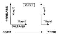
- FIG. 2 is a diagram showing the relationship between the change speed of the operating angle of the intake valve 28 and the change speed of the rotational phase of the intake cam 36. More specifically, the diagram on the left side in FIG. 2 shows the change speed (working angle widening speed) of the working angle of the intake valve 28 during the small working angle control and the advance side of the rotational phase of the intake cam 36. The relationship with the change speed (phase advance speed) is shown, and the diagram on the right side in FIG. 2 shows the relation between the action angle expansion speed and the phase advance speed during the large action angle control.
- the phase variable mechanism 32b is a hydraulic drive type, and the operating angle variable mechanism 32a is an electric type. For this reason, the response speed of the phase variable mechanism 32b is slower than that of the operating angle variable mechanism 32a. Further, when the operating angle increases, the reaction force from the valve spring (not shown) that acts on the intake cam 36 increases. This cam reaction force acts to prevent the rotational phase of the intake cam 36 from being controlled to the advance side. For this reason, as shown in FIG. 2, the working angle expansion speed does not change with respect to the change of the working angle, whereas when the working angle increases, the phase advance speed decreases.
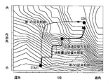
- FIG. 3 and 4 are diagrams for explaining the characteristic control method (state quantity tracking priority control) in the first embodiment of the present invention in comparison with the first and second conventional controls.
- the vertical axis in FIG. 3 is the operating angle (intake valve closing timing IVC) of the intake valve 28 adjusted by the operating angle variable mechanism 32a
- the horizontal axis in FIG. 3 is the intake cam 36 adjusted by the phase variable mechanism 32b.
- IVC intake valve opening timing
- the striped pattern shown in FIG. 3 is a contour line of the compression end temperature, and the compression end temperature becomes higher as it moves to the upper right side in FIG. 4A shows a waveform representing a change in the fuel injection amount Q, FIG.
- FIG. 4B shows a waveform representing a change in the operating angle of the intake valve 28, and FIG. 4C shows a phase of the intake cam 36.
- FIG. 4D shows a waveform representing a change in total hydrocarbon (THC)
- FIG. 4E shows a waveform representing a change in compression end temperature.
- the increase in the operating angle and the advance angle of the phase are required at the same time, for example, as shown in FIG. 4A, the acceleration in which the fuel injection amount Q is increased based on the accelerator request.
- Time that is, when the operating state shifts to the high load high rotation side.
- the control points indicated by “START” in FIG. 3 are those at the start of acceleration, and the control points indicated by “GOAL” in FIG. 3 are those at the end of acceleration (that is, this time This is the target for acceleration).
- the performance of the internal combustion engine 10 is divided into individual operation regions finely divided in the operation region of the internal combustion engine 10 defined by the engine load (fuel injection amount Q) and the engine speed.
- Fuel consumption performance, output performance, etc. are set that are important driving state quantities.
- the target value of the operating state amount (that is, the target) is determined according to the operating region after the transition (that is, according to the required fuel injection amount Q).
- (State quantity) is set, and target values (target action angle and target phase) of the operation values (action angle and phase) of the variable mechanisms 32a and 32b for realizing the target state quantity are set.
- the performance (exhaust emission performance, fuel consumption performance, or output performance) of the internal combustion engine 10 in the process of transition of the operating angle and phase to each target value Etc.) it is preferable to always keep the operating state quantity important for satisfying the target state quantity as close as possible.
- the compression end temperature is controlled as such an operation state quantity. If the compression end temperature can always be controlled to an appropriate value as much as possible during the transition, the combustion state during the transition can be improved and the deterioration of the THC emission amount can be suppressed. Therefore, in the present embodiment, the state quantity tracking priority control is performed when the expansion of the working angle and the phase advance angle are required during acceleration or the like.
- the first conventional control is performed without any consideration when an increase in operating angle and a phase advance are required during acceleration when the fuel injection amount Q is increased.
- the control of the working angle and the phase toward each target value is started simultaneously.
- the working angle with a relatively high response speed first converges to the target value, and thereafter The phase having a relatively low response speed converges to the target value.
- the convergence of the compression end temperature to the target state quantity (value in “GOAL” in FIG. 3) is delayed.
- the phase advance is performed under a situation where the phase advance speed is lowered due to an increase in the cam reaction force accompanying the increase in the operating angle.
- consideration is not given to always bringing the compression end temperature as close as possible to the target state quantity in the process of controlling the operating angle and phase toward each target value. As a result, as shown in FIG. 4D, it is not possible to suppress the deterioration of the THC emission amount during acceleration.
- the operating angle and the phase advance angle are required during acceleration,
- the phase is first controlled to the target value in a state where the operating angle is not enlarged, and then the operating angle is controlled to the target value.
- the operating angle can be converged to the target value after the phase is quickly converged to the target value while the phase advance speed is kept high.
- consideration is not given to always bringing the compression end temperature as close as possible to the target state quantity in the process of shifting to the target operating angle and the target phase. Therefore, although the working angle and phase can be quickly converged to the respective target values, as shown in FIG.
- the compression end temperature is always set to the target in the transition process to the target working angle and target phase.
- the working angle and phase do not change in a path that is as close as possible to the state quantity.
- FIG. 4D the deterioration of the THC emission amount during acceleration cannot be sufficiently suppressed.
- a thin solid line in FIG. 3 is a path along which the operating angle and phase follow the state quantity tracking priority control of the present embodiment.
- subjected on this continuous line represents the variation
- the phase change speed (more specifically, the phase advance speed) decreases as the operating angle increases. For this reason, in FIG. 3, the phase arrow becomes shorter as the operating angle increases.
- the state quantity tracking priority control when an increase in the operating angle and an advance angle of the phase are required during acceleration, as shown by a thin solid line in FIG.
- For each predetermined time the above minimum time that can be calculated by the ECU 50 is desirable
- whether the compression end temperature that is the operation state quantity approaches the target state quantity sooner is calculated when the operation is performed with priority.
- Which of the operating angle and the phase is to be preferentially moved is determined.
- the adjustment that is determined to have a high change rate of the compression end temperature is performed with priority over the other adjustment.
- the change in the operating angle and the phase is different from that during the execution of the first and second conventional controls, as shown in FIGS. 4 (B) and 4 (C).
- the working angle and the phase are set so that the compression end temperature can always be as close as possible to the target state quantity. Will be controlled.
- FIG. 4D it is possible to most suppress the deterioration of the exhaust emission (in this case, the THC emission amount) in the process of shifting to the target state quantity (that is, during transition).
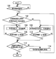
- FIG. 5 is a flowchart showing a control routine executed by the ECU 50 in order to realize the state quantity tracking priority control in the first embodiment of the present invention.
- the routine shown in FIG. 5 it is first determined whether or not the fuel injection amount Q has increased (step 100).
- the case where the operating angle is expanded is larger than the case where the phase is advanced.
- the rate of change in the compression end temperature (here, the rate of increase in the compression end temperature) increases (step 102).
- the ECU 50 is a map (compression end temperature map) that defines the relationship as shown in FIG. 3, that is, the compression end temperature increase rate with respect to the change in the working angle (IVC) and the compression end temperature increase rate with respect to the change in the phase (IVO). ) Is remembered.
- the magnitude of the calculated value of the compression end temperature increase rate is compared between when the working angle is expanded and when the phase is advanced.
- FIG. 6 is a diagram for explaining the determination method in step 102 in more detail.
- the phase advance angle is larger than the action angle enlargement. It can be seen that the compression end temperature rise rate is higher.
- the working angle is larger than the phase advance angle. It can be seen that the rate of increase in the compression end temperature is higher with enlargement.
- step 104 If it is determined that the determination in step 102 is satisfied, it can be determined that the adjustment of the operating angle should be prioritized, and therefore control with priority given to the adjustment of the operating angle is executed (step 104). .
- the working angle is expanded and the phase is advanced.
- the reason why the phase is advanced in addition to the expansion of the operating angle is that the change in the phase does not affect the adjustment of the operating angle using the electric motor as a driving force. This is because the phase can be converged earlier to the target phase by simultaneously performing the phase advance angle.
- the adjustment of the operating angle uses the electric operating angle variable mechanism 32a having a higher response speed than the hydraulic phase variable mechanism 32b used for adjusting the phase. Even if the phase advance is performed simultaneously, it can be said that the control is given priority to the expansion of the working angle.
- a predetermined time that is, the minimum time that can be calculated by the ECU 50
- T the time when the operating angle was expanded in step 104
- step 108 determines whether or not the phase advance angle is continued while the predetermined time T has not yet elapsed.
- step 106 or 110 it is then determined whether or not the operating angle and phase have reached the target operating angle and target phase, respectively (step 112). As a result, when it is determined that the determination in step 112 is established, the state amount tracking priority control of the present embodiment is terminated. On the other hand, when it is determined that the determination in step 112 is not established, the phase change speed W n is calculated (step 114). As described above, since the phase change speed W n changes depending on the operating angle, in this step 114, the latest phase change speed W n corresponding to the current operating angle is calculated. The phase change speed W n calculated here is used when calculating the rate of change of the compression end temperature due to the phase change in the determination in step 102. After execution of this step 114, the processing after step 102 is repeatedly executed.
- the operating angle and phase are controlled so that the compression end temperature is always as close as possible to the target state quantity at each predetermined time T in the transition process to the target state quantity. become.
- the combustion state in the transition process to the target state quantity (that is, at the time of transition) can always be made optimal, so that deterioration of exhaust emission (in this case, THC emissions) can be sufficiently suppressed. It becomes possible.
- the effect of the phase adjustment using the phase variable mechanism 32b having a slower response speed than the operating angle variable mechanism 32a is obtained on the hardware of the phase variable mechanism 32b. It becomes possible to draw out the limit of response performance.
- the operation state quantity to be controlled in the present invention is not limited to the compression end temperature, and may be, for example, an intake air quantity or a pump loss as described below.
- the phase variable mechanism 32b corresponds to the “first actuator” in the first invention
- the operating angle variable mechanism 32a corresponds to the “second actuator” in the first invention. is doing.
- the “control means” in the first invention executes the processing of the above step 102
- the “state quantity determining means in the first invention of the first invention "Is realized.
- the ECU 50 executes the processing of step 108, thereby realizing the “working angle adjustment stopping means” in the third aspect of the invention.
- Embodiment 2 a second embodiment of the present invention will be described with reference to FIG. 7 and FIG.
- the system of the present embodiment can be realized by causing the ECU 50 to execute a routine shown in FIG. 8 described later instead of the routine shown in FIG. 5 using the hardware configuration shown in FIG.
- FIG. 7 is a diagram for explaining an adverse effect due to distortion that may occur in the compression end temperature increase rate map.
- the compression end temperature operating state quantity
- the remaining working angle and phase are 1 It is necessary to move each time.
- the map shown in FIG. 7 if the phase is advanced to the current state quantity ( ⁇ ) before the operating angle, the compression end temperature becomes larger than the target state quantity.
- map distortion The map setting in which such a phenomenon occurs is referred to as map distortion here.
- map distortion the case where the map distortion is generated on the phase side is taken as an example, but the same map distortion can be generated on the working angle side, and the phase side and the working angle side are also affected. It can occur in both.
- the adjustment that is determined to have a high rate of change in the compression end temperature among the adjustment of the operating angle and the adjustment of the phase is performed with priority. become.
- the map distortion as shown in FIG. 7 occurs, if such control is applied as it is, the compression end temperature will overshoot beyond the target state quantity, resulting in excessive rise. There is a case.
- an overshoot of the compression end temperature (operation state quantity) with respect to the target state quantity is predicted by adjusting the working angle or the phase.
- the other adjustment in which the overshoot is not predicted is preferentially performed. That is, even if the adjustment for which overshoot is predicted is the adjustment with the higher change rate of the compression end temperature, the execution of the adjustment is limited.
- the overshoot is predicted by either the adjustment of the working angle or the adjustment of the phase, the adjustment of the working angle is stopped so that the final target value can be reached sooner. First, the working angle is expanded after the phase is advanced.
- FIG. 8 is a flowchart showing a control routine executed by the ECU 50 in the second embodiment in order to realize the above function.
- the same steps as those shown in FIG. 5 in the first embodiment are denoted by the same reference numerals, and the description thereof is omitted or simplified.
- step 102 when it is determined that the determination in step 102 is established, that is, when it can be determined that the adjustment of the operating angle should be prioritized, the current operating angle is then determined. It is determined whether or not the target state quantity is smaller than the target state quantity (step 200).
- step 200 If it is determined in step 200 that the current state quantity of the operating angle is smaller than the target state quantity, it can be determined that the overshoot caused by the map distortion is not predicted. . Therefore, in this case, the working angle is expanded as usual (step 104). On the other hand, if it is determined in step 200 that the current state quantity of the working angle is greater than or equal to the target state quantity, an overshoot caused by the map distortion is predicted due to the expansion of the working angle. It can be judged that there is. For this reason, in this case, adjustment in which overshoot is predicted (that is, operation angle expansion) is limited, and the phase advance is performed while the current operation angle is maintained (step 108).
- overshoot that is, operation angle expansion
- step 102 If it is determined that the determination in step 102 is not established, that is, if it can be determined that the phase adjustment should be prioritized, then the current state quantity of the target for the phase Is smaller than the target state quantity (step 202).
- step 202 If it is determined in step 202 that the current state quantity of the phase is smaller than the target state quantity, it is possible to determine that the overshoot caused by the map distortion is not predicted. Therefore, in this case, the phase advance angle is executed as usual with the current operating angle maintained (step 108). On the other hand, when it is determined in step 202 that the current state quantity of the phase is greater than or equal to the target state quantity, an overshoot caused by the map distortion is predicted by the phase advance angle. It can be judged. In this case, the determination in step 200 is then executed.
- step 104 when the overshoot due to the map distortion is not predicted due to the expansion of the operating angle (when the determination of step 200 is established), the process proceeds to step 104.
- an overshoot due to the map distortion is predicted even when the operating angle is expanded (when the determination of step 200 is not established), in order to reach the final target value earlier.
- the phase advance angle is executed in a state where the current operating angle is maintained (step 108).
- the adjustment of the predicted overshoot is compressed. Even with the adjustment with the higher end temperature change rate, the execution of the adjustment is limited. Thereby, the adverse effect (traverse) due to the map distortion can be suppressed. More specifically, when the compression end temperature is used as the operation state quantity as in the present embodiment, an increase in the NOx emission amount due to the excessive compression end temperature can be suppressed.
- the “overshoot predicting means” in the fourth aspect of the invention is not satisfied in the determination of step 200.
- the process of step 108 is executed by executing the process of step 104 or when the determination of step 202 is not established and the determination of step 200 is established. "Overshoot control means" is realized respectively.
- Embodiment 3 FIG. Next, Embodiment 3 of the present invention will be described with reference to FIG. 9 and FIG.
- the system of the present embodiment can be realized by causing the ECU 50 to execute a routine shown in FIG. 9 described later instead of the routine shown in FIG. 5 using the hardware configuration shown in FIG.
- the operating state quantity may not be able to converge to the target state quantity indefinitely. is there. In some cases, due to demands such as drivability of the internal combustion engine 10, it is required that the operating angle and phase follow each target value relatively early.
- the time required for the phase to reach the target phase at each time point during the transition and the working angle to reach the target working angle is a predetermined time (the time limit (U) described later).
- the above-described state quantity tracking priority control is performed.
- the state quantity follow-up priority control in which the followability of the driving state quantity has the highest priority is followed by the prompt follow-up of the phase and the working angle to the target phase and the target working angle. Changed to high-speed tracking priority control that gives top priority to safety.
- FIG. 9 is a flowchart showing a control routine executed by the ECU 50 in the third embodiment in order to realize the above function.
- the same steps as those shown in FIG. 5 in the first embodiment are denoted by the same reference numerals, and the description thereof is omitted or simplified.
- step 100 if it is determined in step 100 that the fuel injection amount Q has increased, then the target value arrival limit time U for the operating angle and phase during the current acceleration is determined (step). 300).
- This target value arrival limit time U is a time determined as the upper limit of the required time when the operating angle and phase are controlled to the respective target values using only the state quantity tracking priority control during the current acceleration.
- step 106 or 110 if it is determined in step 106 or 110 that the predetermined time T has elapsed, then the phase change speed W n , the difference A between the target operating angle and the current operating angle, Then, a difference B between the target phase and the current phase is calculated (step 302).
- the sum (A / V) of the time required to control the operating angle by the difference A (A / V) and the time required to control the phase by the difference B (B / W n ) V + B / W n ) is greater than or equal to the value (UT ⁇ n) obtained by subtracting the control time (T ⁇ n) of the working angle and phase from the target value arrival limit time U to the current time during the current acceleration. It is determined whether or not there is (step 304).
- V is the working angle change speed.
- the above sum (A / V + B / W n ) corresponds to the time required for the operating angle and phase to reach the respective target values from the current control time point.
- the difference (UT ⁇ n) described above is the time remaining at the present point in time when controlling the operating angle and the phase to the respective target values using only the state quantity tracking priority control at the time of the current acceleration ( Time limit).
- step 304 when it is determined that the determination in step 304 is not established, that is, the operating angle and the phase can be shifted to the target values within the time limit (UT ⁇ n) only by the state quantity tracking priority control. If it can be determined, the normal processing after step 114 is executed, that is, the state quantity tracking priority control is continued.
- step 304 determines whether the determination in step 304 is satisfied, that is, if the operating angle and phase cannot be shifted to the target values within the time limit (UT ⁇ n) only by the state quantity tracking priority control, respectively. If it can be determined, the state amount tracking priority control is switched to the high speed tracking priority control (steps 306 to 312).
- the phase advance angle is executed with the current operating angle maintained (step 306). It is then determined whether the current phase has reached the target phase (step 308). As a result, when the current phase reaches the target phase, the operating angle is expanded (step 310). Next, it is determined whether or not the current operating angle has reached the target operating angle (step 312). As a result, when the current operating angle reaches the target phase, the fast tracking priority control is terminated.
- FIG. 10 is a diagram for explaining a path followed by an operating angle and a phase when the state quantity tracking priority control is switched to the high speed tracking priority control during the transition to the target state quantity.
- the target angle is first reached in a state in which it is considered that the phase change speed W n is not lowered by fixing the operating angle.
- the phase is advanced as follows. Next, the operating angle is expanded so as to reach the target operating angle. As a result, the operating angle and the phase can be quickly followed to the respective target values. For this reason, according to the control of the present embodiment, the deterioration of exhaust emission at the time of transition is suppressed as much as possible by executing the state quantity tracking priority control, and the phase to the target phase and the target working angle and the working angle as necessary. It becomes possible to reach the target phase and the target operating angle within the time limit by making the follow-up of the above-mentioned fast by the execution of the high-speed follow-up priority control.
- control switching means is realized by the ECU 50 executing the series of processes in steps 306 to 312 when the determination in step 304 is satisfied. Has been.
- Embodiment 4 FIG. Next, a fourth embodiment of the present invention will be described with reference to FIG.
- the system according to the present embodiment is configured in the same manner as the system according to the first embodiment described above, except that the system described with reference to FIG.
- FIG. 11 is a diagram for explaining a characteristic configuration in the fourth embodiment of the present invention.
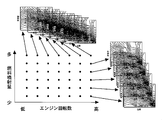
- the sensitivity of the operation state quantity here, the compression end temperature
- the contour line (striped pattern) of the compression end temperature in the relationship between the working angle and the phase shown in FIG. 3 and the like changes.
- the compression end temperature map for each predetermined engine speed and predetermined engine load (fuel injection amount), it is possible to more accurately improve the deterioration of exhaust emissions during the transition. It can be suppressed well. Further, even when the temperature is other than the compression end temperature, for example, if the operation state quantity to be controlled is set to the intake air quantity, the deterioration of the smoke emission amount and the deterioration of the drivability of the internal combustion engine 10 can be more accurately suppressed. In addition, if the operating state quantity to be controlled is the pump loss, the deterioration of fuel consumption can be suppressed more accurately.
- Embodiment 5 FIG. Next, a fifth embodiment of the present invention will be described.
- System of this embodiment except that is characterized in the method of calculating the phase change rate W n, assumed to be configured similar to the system 1 such as the above-described embodiment.
- phase change speed W n changes according to not only the operating angle described above but also the oil temperature and hydraulic pressure.
- the oil pressure changes according to the engine speed. Therefore, in this embodiment, as described below, working angle and phase change speed W n, and to define the oil temperature, and oil pressure (engine speed) as a function of the variables.
- Phase change speed W n f (working angle ⁇ working angle variable mechanism deterioration correction coefficient, oil temperature, hydraulic pressure,...) ⁇ phase variable mechanism deterioration correction coefficient
- the response speed of the phase variable mechanism 32b (the same applies to the operating angle variable mechanism 32a) is lowered due to deterioration over time. Therefore, in the present embodiment, as described above, the phase change speed W n is corrected using the phase variable mechanism deterioration correction coefficient in consideration of the degree of deterioration with time of the phase variable mechanism 32b. In the present embodiment, similarly, an action which is a variable of the above function of the phase change speed W n in consideration of the degree of deterioration with time of the action angle variable mechanism 32a using the action angle variable mechanism deterioration correction coefficient. Fixed corners.
- deterioration correction coefficients can be calculated based on changes over time in the response time when operating the phase or the working angle by a predetermined amount, and these deterioration correction coefficients are calculated based on the total operation time of the internal combustion engine 10. Alternatively, it can be determined based on the travel distance of the vehicle on which the internal combustion engine 10 is mounted.
- the phase change speed W n is determined as a function having the operating angle, the oil temperature, and the hydraulic pressure (engine speed) as variables, so that the exhaust emission, fuel consumption, or Deterioration in drivability and the like can be suppressed with higher accuracy.
- the phase change speed W n is corrected using the above-described deterioration correction coefficient, it is possible to maintain the state quantity tracking priority control with high accuracy over a long period of time.
- Embodiment 6 FIG. Next, a sixth embodiment of the present invention will be described with reference to FIGS.
- the system of this embodiment can be realized by causing the ECU 50 to execute a routine shown in FIG. 13 described later instead of the routine shown in FIG. 5 using the hardware configuration shown in FIG.
- FIG. 12 is a diagram for explaining setting of the operation region of the internal combustion engine 10 used in the sixth embodiment of the present invention.
- the output to be prioritized in the internal combustion engine 10 (exhaust emission, fuel consumption, smoke emission, drivability, etc.) varies depending on the operating region of the internal combustion engine 10. More specifically, reduction of exhaust emission (especially THC) is given the highest priority in the low-rotation and low-load region indicated by the symbol “A” in FIG.
- the low rotation and high load region indicated by the symbol “B” in FIG. 12 is a region required at the time of full-open acceleration, and in this region, the smoke discharge amount is ensured to ensure acceleration performance (output performance).
- Reduction (and prevention of deterioration of drivability) is a top priority area.
- the intake air amount tends to be insufficient.
- the fuel is not used sufficiently for torque generation and is discharged as smoke, resulting in a deterioration in acceleration performance. For this reason, in order to ensure acceleration performance, reduction of smoke emission amount is required.
- a mode region (low, medium rotation, and low and medium load region) indicated by reference numeral “C” in FIG. 12 is a normal region that is frequently used during operation of the internal combustion engine 10, and in this region, the internal combustion engine Of the 10 outputs, fuel consumption, and exhaust emission, reduction of exhaust emission (especially NOx) is given the highest priority. Further, in the high rotation and high load region indicated by the reference sign “D” in FIG.
- the A mode in which the compression end temperature (the rate of increase) is the operation state amount is the state amount control mode M. n was selected.
- the B mode in which the intake air amount is the operation state amount is selected as the state amount control mode M n .
- the C region that is, the mode region
- the C mode in which the compression end temperature (decrease rate) is the operation state quantity is selected as the state quantity control mode M n .
- the D mode in which the pump loss is the operation state quantity is selected as the state quantity control mode M n .
- FIG. 13 is a flowchart showing a control routine executed by the ECU 50 in the sixth embodiment in order to realize the above function.
- the same steps as those shown in FIG. 5 in the first embodiment are denoted by the same reference numerals, and the description thereof is omitted or simplified.
- the current operating region of the internal combustion engine 10 on the map (relationship as shown in FIG. 12) of the engine speed NE and the fuel injection amount Q (engine load) is ascertained.
- the current state quantity control mode M n corresponding to the driving region is recognized (step 400). Specifically, in this step 400, the state quantity control mode M n corresponding to the current operation region is acquired from the above four modes A to D.
- step 402 when it is determined in step 100 that the fuel injection amount Q has increased, the operating state in the current state quantity control mode M n is greater when the operating angle is expanded than when the phase is advanced. It is determined whether or not the improvement rate (change rate) of the amount is high (step 402).
- the ECU 50 stores a map in which the operating state quantity is determined by the relationship between the operating angle and the phase for each state quantity control mode M n .
- running state quantity according to the present state quantity control mode Mn is referred, and said determination is performed.
- the operation angle expansion step 104) accompanied by the phase advance angle or the phase advance angle (step 108) in a state where the operation angle change is stopped is executed.
- step 112 when it is determined in step 112 that both the operating angle and the phase have not reached the respective target values, the phase change speed W n is calculated (step 114), and the next state quantity control is performed. It is determined whether or not the mode M n + 1 is equal to the current state quantity control mode M n (step 404). That is, in this step 404, the next state quantity control mode M n + 1 is recognized in accordance with the latest engine speed NE and fuel injection quantity Q at the present time, and whether or not the state quantity control mode M n is switched is determined. To be judged.
- next state quantity control mode M n + 1 is equal to the current state quantity control mode M n
- the processing after step 402 is immediately repeated.
- next state quantity control mode M n + 1 and the current state quantity control mode M n are not equal, that is, when it can be determined that the state quantity control mode M n should be switched.
- the map of the operation state quantity to be referred to is changed to the map of the operation state quantity corresponding to the next state quantity control mode M n + 1 (step 406).
- the processing after step 402 is repeatedly executed.
- FIG. 14 is a diagram for explaining an example of switching of the map of the operation state quantity in the present step 406. More specifically, in the example shown in FIG. 14, the increase in intake air amount for reducing smoke discharge amount is given the highest priority from the A mode in which the increase in compression end temperature for reducing THC discharge amount is given the highest priority. This is a case where the state quantity control mode Mn is switched to the B mode. In this case, as shown in FIG. 14, when the operating region of the internal combustion engine 10 changes from the A region to the B region and reaches the map switching boundary, the suction from the compression end temperature (increase rate) map is performed. The operation state quantity map is switched to the air quantity map.
- FIG. 15 is a diagram for explaining the operation at the time of transition (acceleration) in which the operation region of the internal combustion engine 10 changes from the A region to the B region in FIG. More specifically, FIG. 15A shows a waveform representing the change in the fuel injection amount Q, and FIG. 15B shows the opening timing (IVO) of the intake valve 28 as a result of the change in the phase of the intake cam 36.
- a waveform representing a change in the advance amount and a waveform representing a change in the closing timing (IVC) of the intake valve 28 as a result of a change in the phase of the intake cam 36 and a change in the operating angle of the intake valve 28 are shown in FIG. )
- FIG. 15D represents a waveform representing a change in total hydrocarbons (THC)
- FIG. 15E represents a waveform representing a smoke emission amount change. Show.
- the broken line in each figure in FIG. 15 is the target value of each parameter.
- the compression end temperature is controlled so as to become the target state quantity at the time of transition with reference to the compression end temperature map. More specifically, as shown in FIGS. 15 (B) and 15 (C), when the phase advance angle is prioritized, the phase is advanced while the working angle is fixed. The opening timing (IVO) of the valve 28 is advanced. Thereby, since the amount of intake air increases, the compression end pressure increases, and as a result, the compression end temperature increases. Further, when priority is given to the expansion of the working angle, the working angle is expanded with a phase advance angle. As described above, since the response speed of the operating angle is higher than the response speed of the phase, the closing timing (IVC) of the intake valve 28 is retarded.
- the operating state amount map is switched to the intake air amount map. It is done.
- the intake air amount is controlled with reference to the map of the intake air amount so that the intake air amount becomes the target state amount during the transition. More specifically, as shown in FIGS. 15 (B) and 15 (C), when the phase advance angle is prioritized, the phase is advanced while the working angle is fixed. The opening timing (IVO) of the valve 28 is advanced. Thereby, the amount of intake air increases.
- the operating angle is increased with the phase advance angle, so that the closing timing (IVC) of the intake valve 28 is delayed beyond the intake bottom dead center. become.
- the amount of intake air increases.
- the intake air amount is always brought as close as possible to the target state amount at the time of transition. Therefore, as shown in FIG. 15 (E), the intake air amount tends to be insufficient.
- the smoke discharge amount can be suppressed as the target value.
- the amount of intake air rather than the compression end temperature is set as the operation state amount to be controlled, so that the THC discharge amount slightly deviates from the target value as shown in FIG. There is also.
- the region B low rotation and high load region
- the THC emission amount is suppressed as intended.
- the smoke discharge amount can be suppressed as intended.
- the smoke emission amount is a main factor that limits the increase in the fuel injection amount. According to the above control, the fuel injection amount can be further increased by reducing the smoke discharge amount during the transition in such an operation region. For this reason, it is possible to increase the low-speed torque.
- the control target is given priority in accordance with each operation region (A to D) of the internal combustion engine 10.
- the map of the driving state quantity is switched.
- the target values of the operating angle and phase are simply set according to the target outputs (exhaust emission, fuel consumption, smoke emission, drivability, etc.) that differ depending on the operating region of the internal combustion engine.
- the conventional method of changing is known. However, with this conventional method, even if output can be optimized after convergence of the target value, instantaneous deterioration of fuel consumption or exhaust emission is suppressed immediately after output switching during transition. Can not do it.
- the state quantity tracking priority control is executed. For this reason, even immediately after switching, the operating angle and phase can be controlled so that the operating state quantity can be as close as possible to the target state quantity as much as possible. As a result, it is possible to minimize exhaust emissions, fuel consumption, drivability, and the like during transition including when switching output according to the operation region.
- the “state quantity switching means” according to the ninth aspect of the present invention is realized by the ECU 50 executing the processing of steps 404 and 406 described above.
- the state quantity tracking priority control described above is performed using the relationship of the map of the operation state quantity to be controlled at the time of transition.
- the state quantity tracking priority control in the present invention is not limited to that performed with reference to the map as described above.
- the following method may be used.
- the compression end temperature can be calculated from the in-cylinder pressure according to a known relational expression, and the in-cylinder pressure can be calculated according to the known relational expression, the intake air amount, the operating angle of the intake valve 28, the phase of the intake cam 36, the fuel It can be calculated based on the injection amount, the intake air temperature, and the like. Therefore, by using these relational expressions, it is possible to calculate how much the change rate of the compression end temperature will be when the working angle changes within a predetermined time with a possible change in the response speed of the actuator. it can. Similarly, the change rate of the compression end temperature can be calculated for the phase change.
- the magnitude is determined at predetermined time intervals, whereby the map It is possible to determine at any given time in the transition time which of the operating angle and the phase should be controlled without using. Further, when the operating state quantity is, for example, the intake air quantity or the pump loss, it can be performed using a known relational expression as in the case of the compression end temperature.
- the configuration using the hydraulically driven phase variable mechanism 32b and the electric operating angle variable mechanism 32a that is, the operating angle is larger than that of the first actuator that adjusts the phase.
- the second actuator to be adjusted has been described by taking as an example a configuration with a higher response speed.
- the subject of the present invention is not limited to such a configuration, and the second actuator that adjusts the phase may have a higher response speed than the first actuator that adjusts the operating angle. .
- control for the intake valve 28 has been described.
- the control of the present invention is not limited to the target for the intake valve, and may be for the exhaust valve.
- a working angle variable mechanism that continuously varies the working angle of the exhaust valve 30 and the rotation of the exhaust cam with respect to the rotation phase of the crankshaft.
- the control of the first embodiment described above may be applied to the control of the exhaust valve 30 after the exhaust variable valve operating apparatus having the phase variable mechanism that continuously varies the phase is provided.
Landscapes
- Engineering & Computer Science (AREA)
- Chemical & Material Sciences (AREA)
- Combustion & Propulsion (AREA)
- Mechanical Engineering (AREA)
- General Engineering & Computer Science (AREA)
- Output Control And Ontrol Of Special Type Engine (AREA)
Abstract
カムの回転位相および吸気弁または排気弁の作用角を制御するための、応答速度の異なる2つのアクチュエータを備える内燃機関において、過渡時に運転状態量が目標状態量に常にできるだけ近づけられるようにした内燃機関の制御装置を提供する。 吸気カム(36)の回転位相を調整する油圧駆動式位相可変機構(32b)と、吸気弁(28)の作用角を調整する電動式作用角可変機構(32a)とを備える。内燃機関(10)の運転状態が変化する過渡時に、吸気カム(36)の回転位相の調整と吸気弁(28)の作用角の調整のうちのどちらによる圧縮端温度(運転状態量)の変化率が高いかを所定時間毎に判定する。そして、吸気カム(36)の回転位相の調整と吸気弁(28)の作用角の調整のうちで、圧縮端温度の変化率が高いと判定された方の調整を他方の調整に優先して行う状態量追従優先制御を実行する。
Description
この発明は、内燃機関の制御装置に関する。
従来、例えば特許文献1には、油圧駆動式位相可変機構(リフトタイミング変更機構)と、これよりも応答速度の高い電動式作用角可変機構(リフト量変更機構)とを備える内燃機関の動弁装置の制御装置が開示されている。この従来の制御装置では、内燃機関の運転状態が変化する過渡時に、上記2つの可変動弁機構の応答性を考慮しつつ、内燃機関に対する要求特性(出力トルク、燃費、および排気エミッション)が最適な特性となるように、それぞれの可変動弁機構の動作目標値(リフト量など)を決定している。そのうえで、上記動作目標値が実現可能な動作範囲内にないときは、上記動作目標値を実現可能な動作範囲内の値に変更するようにしている。
尚、出願人は、本発明に関連するものとして、上記の文献を含めて、以下に記載する文献を認識している。
尚、出願人は、本発明に関連するものとして、上記の文献を含めて、以下に記載する文献を認識している。
過渡時における内燃機関の性能(排気エミッション性能、燃費性能、または出力性能など)の悪化もしくは不足を防止するためには、上記可変動弁機構の動作値(カムの回転位相、および吸気弁または排気弁の作用角)がそれぞれの目標値に移行する過程において、内燃機関の上記性能を満足させるうえで重要な運転状態量を、常に目標状態量にできるだけ近づけることが好ましい。しかしながら、上記従来の制御装置は、このような目的のために、応答速度の異なる2つのアクチュエータ(可変動弁機構)の制御手法を提示するものではない。
この発明は、上述のような課題を解決するためになされたもので、カムの回転位相および吸気弁または排気弁の作用角を制御するための、応答速度の異なる2つのアクチュエータを備える内燃機関において、過渡時に運転状態量が目標状態量に常にできるだけ近づけられるようにした内燃機関の制御装置を提供することを目的とする。
第1の発明は、内燃機関の制御装置であって、
クランクシャフトの回転位相に対するカムの回転位相および前記カムにより駆動される吸気弁または排気弁の作用角のうちの一方を調整する第1アクチュエータと、
前記カムの回転位相および前記吸気弁または排気弁の作用角のうちの他方を調整し、前記第1アクチュエータよりも応答速度の高い第2アクチュエータと、
内燃機関の運転状態が変化する過渡時に、前記内燃機関の運転状態を表す所定の運転状態量が目標状態量となるように、前記カムの回転位相および前記弁の作用角をそれぞれ目標位相および目標作用角に向けて制御する制御手段と、
前記過渡時に、前記カムの回転位相の調整と前記吸気弁または排気弁の作用角の調整のうちのどちらによる前記運転状態量の変化率が高いかを所定時間毎に判定する状態量判定手段と、を備え、
前記制御手段は、前記カムの回転位相の調整と前記吸気弁または排気弁の作用角の調整のうちで、前記運転状態量の変化率が高いと判定された方の調整を他方の調整に優先して行う状態量追従優先制御を実行することを特徴とする。
クランクシャフトの回転位相に対するカムの回転位相および前記カムにより駆動される吸気弁または排気弁の作用角のうちの一方を調整する第1アクチュエータと、
前記カムの回転位相および前記吸気弁または排気弁の作用角のうちの他方を調整し、前記第1アクチュエータよりも応答速度の高い第2アクチュエータと、
内燃機関の運転状態が変化する過渡時に、前記内燃機関の運転状態を表す所定の運転状態量が目標状態量となるように、前記カムの回転位相および前記弁の作用角をそれぞれ目標位相および目標作用角に向けて制御する制御手段と、
前記過渡時に、前記カムの回転位相の調整と前記吸気弁または排気弁の作用角の調整のうちのどちらによる前記運転状態量の変化率が高いかを所定時間毎に判定する状態量判定手段と、を備え、
前記制御手段は、前記カムの回転位相の調整と前記吸気弁または排気弁の作用角の調整のうちで、前記運転状態量の変化率が高いと判定された方の調整を他方の調整に優先して行う状態量追従優先制御を実行することを特徴とする。
また、第2の発明は、第1の発明において、
前記運転状態量は、圧縮端温度、吸入空気量、およびポンプ損失のうちの何れか1つであることを特徴とする。
前記運転状態量は、圧縮端温度、吸入空気量、およびポンプ損失のうちの何れか1つであることを特徴とする。
また、第3の発明は、第1または第2の発明において、
前記第1アクチュエータは、前記カムの回転位相を調整する位相可変機構であって、
前記第2アクチュエータは、前記吸気弁または排気弁の作用角を調整する作用角可変機構であって、
前記制御手段は、前記位相可変機構による前記カムの回転位相の調整を優先して行う場合に、前記作用角可変機構による前記吸気弁または排気弁の作用角の調整を中止する作用角調整中止手段を含むことを特徴とする。
前記第1アクチュエータは、前記カムの回転位相を調整する位相可変機構であって、
前記第2アクチュエータは、前記吸気弁または排気弁の作用角を調整する作用角可変機構であって、
前記制御手段は、前記位相可変機構による前記カムの回転位相の調整を優先して行う場合に、前記作用角可変機構による前記吸気弁または排気弁の作用角の調整を中止する作用角調整中止手段を含むことを特徴とする。
また、第4の発明は、第1乃至第3の発明の何れかにおいて、
前記制御手段は、
前記カムの回転位相および前記吸気弁または排気弁の作用角を前記目標位相および前記目標作用角に向けてそれぞれ制御する際に、前記カムの回転位相の調整または前記吸気弁または排気弁の作用角の調整によって前記目標状態量に対する前記運転状態量のオーバーシュートが予測されるか否かを判定するオーバーシュート予測手段と、
前記カムの回転位相の調整および前記吸気弁または排気弁の作用角の調整のうちの何れか一方に前記オーバーシュートが予測される場合には、前記カムの回転位相の調整および前記吸気弁または排気弁の作用角の調整のうちの前記オーバーシュートが予測されない他方を優先して行うオーバーシュート時制御手段と、
を含むことを特徴とする。
前記制御手段は、
前記カムの回転位相および前記吸気弁または排気弁の作用角を前記目標位相および前記目標作用角に向けてそれぞれ制御する際に、前記カムの回転位相の調整または前記吸気弁または排気弁の作用角の調整によって前記目標状態量に対する前記運転状態量のオーバーシュートが予測されるか否かを判定するオーバーシュート予測手段と、
前記カムの回転位相の調整および前記吸気弁または排気弁の作用角の調整のうちの何れか一方に前記オーバーシュートが予測される場合には、前記カムの回転位相の調整および前記吸気弁または排気弁の作用角の調整のうちの前記オーバーシュートが予測されない他方を優先して行うオーバーシュート時制御手段と、
を含むことを特徴とする。
また、第5の発明は、第1乃至第4の発明の何れかにおいて、
前記制御手段は、前記過渡時において、前記カムの回転位相が前記目標位相に到達し、かつ前記吸気弁または排気弁の作用角が前記目標作用角に到達するまでに要する時間が所定時間を超える場合には、前記状態量追従制御から、前記目標位相および前記目標作用角への速やかな追従を優先する高速追従優先制御に切り換える制御切替手段を含むことを特徴とする。
前記制御手段は、前記過渡時において、前記カムの回転位相が前記目標位相に到達し、かつ前記吸気弁または排気弁の作用角が前記目標作用角に到達するまでに要する時間が所定時間を超える場合には、前記状態量追従制御から、前記目標位相および前記目標作用角への速やかな追従を優先する高速追従優先制御に切り換える制御切替手段を含むことを特徴とする。
また、第6の発明は、第1乃至第5の発明の何れかにおいて、
前記状態量判定手段は、前記カムの回転位相の変化に対する前記運転状態量の前記変化率、および前記吸気弁または排気弁の作用角の変化に対する前記運転状態量の前記変化率をそれぞれ定めたマップに従って、前記カムの回転位相の調整と前記吸気弁または排気弁の作用角の調整のうちのどちらによる前記運転状態量の前記変化率が高いかを所定時間毎に判定する手段であって、
前記状態量判定手段は、所定のエンジン回転数および所定のエンジン負荷毎に前記マップを備えていることを特徴とする。
前記状態量判定手段は、前記カムの回転位相の変化に対する前記運転状態量の前記変化率、および前記吸気弁または排気弁の作用角の変化に対する前記運転状態量の前記変化率をそれぞれ定めたマップに従って、前記カムの回転位相の調整と前記吸気弁または排気弁の作用角の調整のうちのどちらによる前記運転状態量の前記変化率が高いかを所定時間毎に判定する手段であって、
前記状態量判定手段は、所定のエンジン回転数および所定のエンジン負荷毎に前記マップを備えていることを特徴とする。
また、第7の発明は、第1乃至第6の発明の何れかにおいて、
前記第1アクチュエータは、油圧を利用して前記カムの回転位相を調整する油圧駆動式位相可変機構であって、
前記状態量判定手段は、前記カムの回転位相の変化速度に基づいて前記カムの回転位相の調整による前記運転状態量の変化率を推定するものであって、
前記カムの回転位相の変化速度は、前記吸気弁または排気弁の作用角、油温、および油圧を変数とする関数として定められていることを特徴とする。
前記第1アクチュエータは、油圧を利用して前記カムの回転位相を調整する油圧駆動式位相可変機構であって、
前記状態量判定手段は、前記カムの回転位相の変化速度に基づいて前記カムの回転位相の調整による前記運転状態量の変化率を推定するものであって、
前記カムの回転位相の変化速度は、前記吸気弁または排気弁の作用角、油温、および油圧を変数とする関数として定められていることを特徴とする。
また、第8の発明は、第7の発明において、
前記カムの回転位相の変化速度は、前記油圧駆動式位相可変機構の経時的な劣化度合いを示す劣化補正係数により修正されることを特徴とする。
前記カムの回転位相の変化速度は、前記油圧駆動式位相可変機構の経時的な劣化度合いを示す劣化補正係数により修正されることを特徴とする。
また、第9の発明は、第1乃至第8の発明の何れかにおいて、
前記内燃機関の運転領域に応じて、制御対象とする前記運転状態量を切り替える状態量切替手段を更に備えることを特徴とする。
前記内燃機関の運転領域に応じて、制御対象とする前記運転状態量を切り替える状態量切替手段を更に備えることを特徴とする。
また、第10の発明は、第9の発明において、
前記状態量切替手段は、低回転低負荷領域では、圧縮端温度を前記運転状態量として選択することを特徴とする。
前記状態量切替手段は、低回転低負荷領域では、圧縮端温度を前記運転状態量として選択することを特徴とする。
また、第11の発明は、第9または第10の発明において、
前記状態量切替手段は、低回転高負荷領域では、吸入空気量を前記運転状態量として選択することを特徴とする。
前記状態量切替手段は、低回転高負荷領域では、吸入空気量を前記運転状態量として選択することを特徴とする。
また、第12の発明は、第9乃至第11の発明の何れかにおいて、
前記状態量切替手段は、排気エミッションの低減を最優先とするモード域では、圧縮端温度を前記運転状態量として選択することを特徴とする。
前記状態量切替手段は、排気エミッションの低減を最優先とするモード域では、圧縮端温度を前記運転状態量として選択することを特徴とする。
また、第13の発明は、第9乃至第12の発明の何れかにおいて、
前記状態量切替手段は、高回転高負荷領域では、ポンプ損失を前記運転状態量として選択することを特徴とする。
前記状態量切替手段は、高回転高負荷領域では、ポンプ損失を前記運転状態量として選択することを特徴とする。
第1および第2の発明によれば、目標状態量への運転状態量の移行過程(すなわち、過渡時)の各瞬間において、運転状態量を常に目標状態量にできるだけ近づけられるようにカムの回転位相と吸気弁または排気弁の作用角とが制御されることになる。その結果、目標状態量への移行過程における内燃機関の性能(排気エミッション性能、燃費性能、または出力性能など)の悪化もしくは不足を十分に抑制することが可能となる。
第2の発明によれば、圧縮端温度、吸入空気量、またはポンプ損失を制御対象の運転状態量としたことにより、過渡時において、内燃機関の性能(排気エミッション性能、燃費性能、または出力性能など)の悪化もしくは不足を十分に抑制することが可能となる。
第3の発明によれば、カムの回転位相の調整を優先して行う場合に、吸気弁または排気弁の作用角の調整を中止することにより、作用角の拡大による位相変化速度の低下を防止することができる。このため、目標状態量への移行過程において、カムの回転位相の調整によって、運転状態量を目標状態量により迅速に近づけられるように制御することができる。
第4の発明によれば、上記オーバーシュートが予測される場合には、当該オーバーシュートの予測される方の調整が運転状態量の変化率の高い方の調整であっても、その調整の実行が制限されるようになる。これにより、運転状態量のオーバーシュートによって内燃機関の上記性能が却って悪化もしくは不足させてしまうのを防止することができる。
第5の発明によれば、過渡時における内燃機関の上記性能の悪化等を上記状態量追従優先制御の実行によってできる限り抑制しつつ、必要に応じて目標位相および目標作用角へのカムの回転位相および吸気弁または排気弁の作用角の追従を高速追従優先制御の実行によって急ぐようにすることにより、制限時間内に目標位相および目標作用角に到達させることが可能となる。
第6の発明によれば、所定のエンジン回転数および所定のエンジン負荷毎に運転状態量についての上記マップを備えておくことにより、過渡時における内燃機関の上記性能の悪化等をより精度良く抑制することができる。
第7の発明によれば、第1アクチュエータとして油圧駆動式位相可変機構を備える場合において、運転状態量の変化率の推定に用いるカムの回転位相の変化速度を精度良く算出することが可能となる。
第8の発明によれば、油圧駆動式位相可変機構の経時的な劣化度合いを考慮して、カムの回転位相の変化速度を精度良く算出することが可能となる。これにより、上記状態量追従優先制御を長期に渡って高精度に保つことが可能となる。
第9の発明によれば、各運転領域に対して最適な運転状態量を、過渡時に目標状態量に常にできるだけ近づけられるようにすることができる。また、運転領域に応じて制御対象とする運転状態量を切り替えながら上記状態量追従優先制御を実行することにより、運転領域の切り替え直後においても、運転状態量を目標状態量に常にできるだけ近づけられるように作用角および位相を制御させられるようになる。
第10の発明によれば、低回転低負荷域において、過渡時に排気エミッション(特にTHC排出量)の悪化を十分に抑制することができる。
第11の発明によれば、低回転高負荷域において、過渡時にスモーク排出量の悪化を抑制して出力性能の不足を十分に抑制することができる。
第12の発明によれば、モード域において、過渡時に排気エミッション(特にNOx排出量)の悪化を十分に抑制することができる。
第13の発明によれば、高回転高負荷域において、過渡時に燃費の悪化を十分に抑制することができる。
実施の形態1.
[システム構成の説明]
図1は、本発明の実施の形態1のシステム構成を説明するための図である。図1に示すシステムは、圧縮着火式の内燃機関10を備えている。ここでは、圧縮着火式内燃機関の一例として、内燃機関10は、ターボ過給機付きのディーゼルエンジンであるものとする。
[システム構成の説明]
図1は、本発明の実施の形態1のシステム構成を説明するための図である。図1に示すシステムは、圧縮着火式の内燃機関10を備えている。ここでは、圧縮着火式内燃機関の一例として、内燃機関10は、ターボ過給機付きのディーゼルエンジンであるものとする。
内燃機関10の筒内には、ピストン12が設けられている。内燃機関10の筒内には、ピストン12の頂部側に燃焼室14が形成されている。燃焼室14には、吸気通路16および排気通路18が連通している。
吸気通路16の入口近傍には、吸気通路16に吸入される空気の流量に応じた信号を出力するエアフローメータ20が設けられている。エアフローメータ20の下流には、ターボ過給機のコンプレッサ22が配置されている。また、排気通路18の途中には、ターボ過給機のタービン24が配置されている。
内燃機関10の各気筒には、燃料を筒内に直接噴射する燃料噴射弁26が設置されている。吸気ポートおよび排気ポートには、それぞれ、燃焼室14と吸気通路16、或いは燃焼室14と排気通路18を導通状態または遮断状態とするための吸気弁28および排気弁30が設けられている。
図1に示すシステムは、各気筒の吸気弁28を駆動するための動弁装置として、吸気可変動弁装置32を備えている。吸気可変動弁装置32は、吸気弁28の作用角(以下、単に「作用角」と略する場合がある)を連続的に可変とする作用角可変機構32aと、クランクシャフト34の回転位相に対する吸気カム36の回転位相(以下、単に「位相」と略する場合がある)を連続的に可変とする位相可変機構(可変バルブタイミング機構)32bとを具備する装置である。より具体的には、作用角可変機構32aは、吸気弁28の開き時期をほぼ一定としつつ作用角を連続的に変更可能な機構であり、また、位相可変機構32bは、作用角を固定としつつ吸気弁28の開閉時期を連続的に変更可能な機構である。従って、これらの可変機構32a、32bを備えることにより、位相可変機構32bを用いた位相の調整によって吸気弁28の開き時期(IVO)を所望の時期に制御しつつ、作用角可変機構32aを用いた作用角の調整によって吸気弁の28の閉じ時期(IVC)を所望の時期に制御することができる。尚、作用角可変機構32aと同様の構成を有する可変動弁装置については、例えば、国際出願の国際公開番号WO2006/132059号公報において詳述されているので、ここではその詳細な説明を省略するものとする。
また、ここでは、上記位相可変機構32bは油圧駆動式の機構であり、上記作用角可変機構32aは電動式の機構であるものとする。また、クランクシャフト34の近傍には、クランク角度およびエンジン回転数を検知するためのクランク角センサ38が配置されている。また、吸気カムシャフト40の近傍には、吸気カムシャフト40の回転位置(位相の進角量)を検知するための吸気カム角センサ42が配置されている。また、作用角可変機構32aは、吸気弁28の作用角を検知するための作用角センサ44を内蔵している。また、吸気通路16におけるコンプレッサ22の下流には、過給圧を検知するための過給圧センサ46および吸気温度を検知するための吸気温センサ48がそれぞれ設置されている。
本実施形態のシステムは、ECU(Electronic Control Unit)50を備えている。ECU50には、上述したエアフローメータ20等に加え、内燃機関10の潤滑油温度(以下、単に「油温」と略する)を検知するための油温センサ52等の各種のセンサが接続されている。また、ECU50には、上述した燃料噴射弁26および吸気可変動弁装置32等の各種のアクチュエータが接続されている。ECU50は、それらのセンサ信号や情報に基づき、所定のプログラムに従って各アクチュエータを駆動させることにより、内燃機関10の運転状態を制御する。
図2は、吸気弁28の作用角の変化速度と吸気カム36の回転位相の変化速度との関係を表した図である。より具体的には、図2における左側の図は、小作用角制御時における吸気弁28の作用角の拡大側の変化速度(作用角拡大速度)と吸気カム36の回転位相の進角側の変化速度(位相進角速度)との関係を示し、図2における右側の図は、大作用角制御時における作用角拡大速度と位相進角速度との関係を示している。
上述したように、位相可変機構32bは油圧駆動式であり、作用角可変機構32aは電動式である。このため、位相可変機構32bの応答速度は、作用角可変機構32aのそれに対して遅くなる。また、作用角が大きくなると、吸気カム36に作用するバルブスプリング(図示省略)からの反力が大きくなる。このカム反力は、吸気カム36の回転位相を進角側に制御するのを妨げるように作用する。このため、図2に示すように、作用角の変化に対して作用角拡大速度は変わらないのに対し、作用角が大きくなると、位相進角速度が低くなる。
[実施の形態1における特徴部分]
図3および図4は、本発明の実施の形態1における特徴的な制御手法(状態量追従優先制御)を第1および第2の従来制御と比較して説明するための図である。
図3における縦軸は、作用角可変機構32aにより調整される吸気弁28の作用角(吸気弁閉じ時期IVC)であり、同図における横軸は、位相可変機構32bにより調整される吸気カム36の位相(吸気弁開き時期IVC)である。また、図3中に示す縞模様は、圧縮端温度の等高線であり、図3における右上側に移動するほど、圧縮端温度が高くなる。また、図4(A)は燃料噴射量Qの変化を表す波形を、図4(B)は吸気弁28の作用角の変化を表す波形を、図4(C)は吸気カム36の位相の変化を表す波形を、図4(D)は総炭化水素(THC)の変化を表す波形を、図4(E)は圧縮端温度の変化を表す波形を、それぞれ示している。
図3および図4は、本発明の実施の形態1における特徴的な制御手法(状態量追従優先制御)を第1および第2の従来制御と比較して説明するための図である。
図3における縦軸は、作用角可変機構32aにより調整される吸気弁28の作用角(吸気弁閉じ時期IVC)であり、同図における横軸は、位相可変機構32bにより調整される吸気カム36の位相(吸気弁開き時期IVC)である。また、図3中に示す縞模様は、圧縮端温度の等高線であり、図3における右上側に移動するほど、圧縮端温度が高くなる。また、図4(A)は燃料噴射量Qの変化を表す波形を、図4(B)は吸気弁28の作用角の変化を表す波形を、図4(C)は吸気カム36の位相の変化を表す波形を、図4(D)は総炭化水素(THC)の変化を表す波形を、図4(E)は圧縮端温度の変化を表す波形を、それぞれ示している。
上記図2に示すように作用角の拡大と位相の進角とが同時に要求されるのは、例えば、図4(A)に示すようにアクセル要求に基づいて燃料噴射量Qが増量される加速時(すなわち、高負荷高回転側への運転状態の移行時)である。図3中に「START」を付して示す制御点は、加速開始時のものであり、同図中に「GOAL」を付して示す制御点は、加速終了時のもの(すなわち、今回の加速時の目標となる点)である。
本実施形態では、エンジン負荷(燃料噴射量Q)とエンジン回転数とで規定される内燃機関10の運転領域において、細かく区分された個々の運転領域毎に、内燃機関10の性能(排気エミッション性能、燃費性能、および出力性能など)を満足させるうえで重要な運転状態量が設定されている。
内燃機関10の運転領域が移行する際(過渡時)には、移行後の運転領域に応じて(すなわち、要求される燃料噴射量Qに応じて)、運転状態量の目標値(すなわち、目標状態量)が設定されるとともに、この目標状態量を実現させるための可変機構32a、32bの動作値(作用角および位相)の目標値(目標作用角および目標位相)がそれぞれ設定される。過渡時に内燃機関10の上記性能の悪化もしくは不足を防止するためには、それぞれの目標値への作用角および位相の移行過程において、内燃機関10の性能(排気エミッション性能、燃費性能、または出力性能など)を満足させるうえで重要な運転状態量を、常に目標状態量にできるだけ近づけることが好ましい。
本実施形態では、過渡時における排気エミッション性能を良好なものとするために、そのような運転状態量として圧縮端温度を制御対象としている。過渡時において圧縮端温度を常にできる限り適切な値に制御することができれば、過渡時における燃焼状態を改善し、THC排出量の悪化を抑制することができる。そこで、本実施形態では、加速時などにおいて作用角の拡大および位相の進角が要求される場合には、状態量追従優先制御を行うようにした。
ここで、本実施形態における過渡時の状態量追従優先制御との対比のために参照する第1および第2の従来制御について先に説明する。
先ず、第1の従来制御は、図4(A)に示すように燃料噴射量Qが増大される加速時において作用角の拡大および位相の進角が要求された場合に、何らの配慮なしに、それぞれの目標値に向けての作用角および位相の制御を同時に開始するものである。このような手法が行われると、図3中の太い実線並びに図4(B)および図4(C)に示すように、応答速度が相対的に高い作用角が先ず目標値に収束し、その後、応答速度が相対的に低い位相が目標値に収束することになる。このような手法では、図4(E)に示すように、目標状態量(図3中の「GOAL」における値)への圧縮端温度の収束が遅れてしまう。その理由は、第1の従来制御では、作用角の拡大に伴うカム反力の増大によって位相進角速度が低くなった状況下で位相の進角が行われるためである。また、第1の従来制御では、それぞれの目標値に向けて作用角および位相を制御していく過程において、圧縮端温度を常に目標状態量にできるだけ近づけるという配慮がなされていない。その結果、図4(D)に示すように、加速時におけるTHC排出量の悪化を抑制することができない。
また、第2の従来の手法は、加速時において作用角の拡大および位相の進角が要求された場合に、図3中の破線並びに図4(B)および図4(C)に示すように、作用角の拡大を行わない状態で先ず位相を目標値に制御させた後に、作用角を目標値に制御させるものである。このような手法によれば、位相進角速度を高く確保した状態で位相を速やかに目標値に収束させたうえで、作用角を目標値に収束させられる。しかしながら、この第2の従来制御においても、目標作用角および目標位相への移行過程において、圧縮端温度を常に目標状態量にできるだけ近づけるという配慮がなされていない。このため、作用角および位相をそれぞれの目標値に迅速に収束させることはできるけれども、図4(E)に示すように、目標作用角および目標位相への移行過程において、圧縮端温度を常に目標状態量にできるだけ近づけられるような経路で作用角および位相が変化しない。その結果、図4(D)に示すように、加速時におけるTHC排出量の悪化を十分に抑制することができない。
これに対し、図3中における細い実線は、本実施形態の状態量追従優先制御に作用角および位相が辿る経路である。そして、この実線上に付された各矢印は、各時点において、ECU50が計算可能な最小時間内に動作し得る作用角および位相の変化量を表している。既述したように、作用角が大きくなるほど、位相変化速度(より具体的には位相進角速度)が低くなる。このため、図3では、作用角の拡大に伴って位相の矢印が短くなっている。
本実施形態の状態量追従優先制御では、加速時において作用角の拡大および位相の進角が要求された場合に、図3中の細い実線で示すように、作用角および位相のうちのどちらを優先して動かした方が、運転状態量である圧縮端温度が目標状態量により早く近づくかを所定時間(ECU50が計算可能な上記最小時間が望ましい)毎に算出し、その算出結果に基づいて、作用角と位相のうちのどちらを優先して動かすかを決定するものである。具体的には、本制御では、上記所定時間毎に、作用角の調整と位相の調整のうちのどちらによる圧縮端温度の変化率が高いかを判定するようにした。そして、作用角の調整と位相の調整のうちで、圧縮端温度の変化率が高いと判定された方の調整を他方の調整に優先して行うようにした。
本実施形態の状態量追従優先制御が行われると、作用角および位相の変化は、第1および第2の従来制御の実行時とは異なり、図4(B)および図4(C)に示すように変化する。このような手法によれば、図4(E)に示すように、目標状態量への移行過程の各瞬間において、圧縮端温度を常に目標状態量にできるだけ近づけられるように作用角と位相とが制御されることになる。その結果、図4(D)に示すように、目標状態量への移行過程(すなわち、過渡時)における排気エミッション(この場合はTHC排出量)の悪化を最も抑制することが可能となる。
図5は、本発明の実施の形態1における状態量追従優先制御を実現するために、ECU50が実行する制御ルーチンを示すフローチャートである。
図5に示すルーチンでは、先ず、燃料噴射量Qが増加したか否かが判定される(ステップ100)。
図5に示すルーチンでは、先ず、燃料噴射量Qが増加したか否かが判定される(ステップ100)。
その結果、燃料噴射量Qが増加したと判定された場合、つまり、加速時(過渡時)であると判断できる場合には、作用角を拡大する場合の方が位相を進角する場合よりも、圧縮端温度の変化率(ここでは、圧縮端温度上昇率)が高くなるか否かが判定される(ステップ102)。ECU50は、上記図3に示すような関係、すなわち、作用角(IVC)の変化に対する圧縮端温度上昇率および位相(IVO)の変化に対する圧縮端温度上昇率をそれぞれ定めたマップ(圧縮端温度マップ)を記憶している。本ステップ102では、そのようなマップを参照して、作用角を拡大する場合と位相を進角する場合とで、圧縮端温度上昇率の算出値の大小が比較される。
図6は、本ステップ102における判定手法をより詳細に説明するための図である。図6中の右上側の矢印の位置においては、作用角の拡大方向よりも位相の進角方向の方が圧縮端温度の等高線が密となっているため、作用角拡大よりも位相進角の方が圧縮端温度上昇率が高くなることが分かる。一方、図6中の左下側の矢印の位置においては、位相の進角方向よりも作用角の拡大方向の方が圧縮端温度の等高線が密となっているため、位相進角よりも作用角拡大の方がより圧縮端温度上昇率が高くなることが分かる。
上記ステップ102における判定が成立すると判定された場合には、作用角の調整を優先すべき状況であると判断することができるので、作用角の調整を優先した制御が実行される(ステップ104)。具体的には、作用角が拡大されるとともに位相が進角される。尚、この場合に、作用角の拡大だけではなく位相の進角を行う理由は、位相の変化は、電動モータを駆動力とする作用角の調整に対して影響を及ぼさないためであり、また、位相の進角を同時に行うことにより、位相を目標位相により早く収束させられるためである。また、上述したように、作用角の調整は、位相の調整に用いられる油圧式の位相可変機構32bよりも応答速度の高い電動式の作用角可変機構32aが用いられるので、作用角の拡大とともに位相の進角を同時に行っても、作用角の拡大を優先させた制御を行っているといえる。
次に、上記ステップ104における作用角拡大時から所定時間(すなわち、ECU50が計算可能な最小時間)Tが経過したか否かが判定される(ステップ106)。その結果、所定時間Tが未だ経過していない間は、作用角拡大(および位相進角)が継続される。
一方、上記ステップ102における判定が不成立であると判定された場合には、位相の調整を優先すべき状況であると判断することができるので、位相の調整を優先した制御が実行される(ステップ108)。具体的には、現状の作用角が維持された状態で(すなわち、作用角の調整が中止された状態で)位相の進角が行われる。次いで、上記ステップ108における位相進角時から上記所定時間Tが経過したか否かが判定される(ステップ110)。その結果、所定時間Tが未だ経過していない間は、位相進角が継続される。
上記ステップ106または110において上記所定時間Tが経過したと判定された場合には、次いで、作用角および位相が目標作用角および目標位相にそれぞれ到達したか否かが判定される(ステップ112)。その結果、本ステップ112の判定が成立したと判定された場合には、本実施形態の状態量追従優先制御が終了される。一方、本ステップ112の判定が不成立であると判定された場合には、位相変化速度Wnが算出される(ステップ114)。既述したように、位相変化速度Wnは作用角に応じて変わるため、本ステップ114では、現在の作用角に応じた最新の位相変化速度Wnが算出される。ここで算出された位相変化速度Wnは、上記ステップ102における判定において、位相の変化による圧縮端温度の変化率を算出する際に使用される。本ステップ114の実行後には、上記ステップ102以降の処理が繰り返し実行される。
以上説明した図5に示すルーチンによれば、目標状態量への移行過程の各所定時間Tにおいて、圧縮端温度を常に目標状態量にできるだけ近づけられるように作用角と位相とが制御されることになる。その結果、目標状態量への移行過程(すなわち、過渡時)における燃焼状態を常に最善なものにすることができるので、排気エミッション(この場合はTHC排出量)の悪化を十分に抑制することが可能となる。また、本実施形態の状態量追従優先制御によれば、作用角可変機構32aに比して応答速度の遅い位相可変機構32bを用いた位相の調整の効果を、位相可変機構32bのハード上の応答性能の限界まで引き出すことができるようになる。
また、上記ルーチンによれば、位相を優先して制御する場合には、作用角が現状の値に維持される。これにより、作用角の拡大による位相変化速度Wnの低下を防止することができるので、目標状態量への移行過程において、位相の調整によって、圧縮端温度を目標状態量により迅速に近づけられるように制御することができる。
ところで、上述した実施の形態1においては、過渡時に制御対象とする運転状態量として、圧縮端温度を用いた制御例について説明した。しかしながら、本発明において制御対象とする運転状態量は、圧縮端温度に限らず、以下に説明するように、例えば、吸入空気量或いはポンプ損失などであってもよい。
尚、上述した実施の形態1においては、位相可変機構32bが前記第1の発明における「第1アクチュエータ」に、作用角可変機構32aが前記第1の発明における「第2アクチュエータ」に、それぞれ相当している。また、ECU50が、上記ステップ104~112の処理を実行することにより前記第1の発明における「制御手段」が、上記ステップ102の処理を実行することにより前記第1の発明における「状態量判定手段」が、それぞれ実現されている。
また、ECU50が上記ステップ102の判定が不成立である場合に上記ステップ108の処理を実行することにより前記第3の発明における「作用角調整中止手段」が実現されている。
また、ECU50が上記ステップ102の判定が不成立である場合に上記ステップ108の処理を実行することにより前記第3の発明における「作用角調整中止手段」が実現されている。
実施の形態2.
次に、図7および図8を参照して、本発明の実施の形態2について説明する。
本実施形態のシステムは、図1に示すハードウェア構成を用いて、ECU50に図5に示すルーチンに代えて後述の図8に示すルーチンを実行させることにより実現することができるものである。
次に、図7および図8を参照して、本発明の実施の形態2について説明する。
本実施形態のシステムは、図1に示すハードウェア構成を用いて、ECU50に図5に示すルーチンに代えて後述の図8に示すルーチンを実行させることにより実現することができるものである。
図7は、圧縮端温度上昇率マップに生じ得る歪みによる弊害を説明するための図である。
図7に示す状態では、作用角および位相の現在値(黒丸)から圧縮端温度(運転状態量)を最終的な目標値(GOAL)に到達させるためには、作用角と位相をそれぞれ残り1回ずつ動かすことが必要である。しかしながら、図7に示すマップの場合には、位相を作用角よりも先に今回の狙いの状態量(△)に進角させると、圧縮端温度が目標状態量よりも過大となってしまう。このような現象が生じてしまうマップの設定のことを、ここではマップ歪みと称する。尚、図7では、位相側に上記マップ歪みが生じているケースを例に挙げたが、同様のマップ歪みは、作用角側にも生じ得るものであり、また、位相側および作用角側の双方にも生じ得るものである。
図7に示す状態では、作用角および位相の現在値(黒丸)から圧縮端温度(運転状態量)を最終的な目標値(GOAL)に到達させるためには、作用角と位相をそれぞれ残り1回ずつ動かすことが必要である。しかしながら、図7に示すマップの場合には、位相を作用角よりも先に今回の狙いの状態量(△)に進角させると、圧縮端温度が目標状態量よりも過大となってしまう。このような現象が生じてしまうマップの設定のことを、ここではマップ歪みと称する。尚、図7では、位相側に上記マップ歪みが生じているケースを例に挙げたが、同様のマップ歪みは、作用角側にも生じ得るものであり、また、位相側および作用角側の双方にも生じ得るものである。
上述した実施の形態1における状態量追従優先制御によれば、作用角の調整と位相の調整のうちで、圧縮端温度の変化率が高いと判定された方の調整が優先して行われることになる。しかしながら、上記図7に示すようなマップ歪みが生じている場合において、このような制御をそのまま適用すると、圧縮端温度が目標状態量を超えてオーバーシュートし、過度に上昇してしまう結果となる場合がある。
そこで、本実施形態では、作用角の調整または位相の調整によって目標状態量に対する圧縮端温度(運転状態量)のオーバーシュートが予測されるか否かを判定するようにした。そのうえで、作用角の調整および位相の調整のうちの何れか一方にオーバーシュートが予測される場合には、当該オーバーシュートが予測されない他方の調整を優先して行うようにした。すなわち、オーバーシュートの予測される方の調整が圧縮端温度の変化率の高い方の調整であっても、その調整の実行を制限するようにした。また、作用角の調整および位相の調整のうちのどちらによっても上記オーバーシュートが予測される場合には、最終的な目標値により早く到達できるようにするために、作用角の調整を停止した状態で先ず位相を進角させた後に作用角を拡大させるようにした。
図8は、上記の機能を実現するために、本実施の形態2においてECU50が実行する制御ルーチンを示すフローチャートである。尚、図8において、実施の形態1における図5に示すステップと同一のステップについては、同一の符号を付してその説明を省略または簡略する。
図8に示すルーチンでは、ステップ102における判定が成立すると判定された場合、すなわち、作用角の調整を優先すべき状況であると判断することができる場合には、次いで、作用角についての今回の狙いの状態量が目標状態量よりも小さいか否かが判定される(ステップ200)。
上記ステップ200において作用角についての今回の狙いの状態量が目標状態量よりも小さいと判定された場合には、上記マップ歪みに起因するオーバーシュートが予測される状況ではないと判断することができる。このため、この場合には、通常通り作用角の拡大が実行される(ステップ104)。一方、上記ステップ200において作用角についての今回の狙いの状態量が目標状態量以上であると判定された場合には、作用角の拡大によって上記マップ歪みに起因するオーバーシュートが予測される状況であると判断することができる。このため、この場合には、オーバーシュートが予測される方の調整(すなわち、作用角拡大)が制限され、現状の作用角が維持された状態で位相の進角が行われる(ステップ108)。
また、上記ステップ102における判定が不成立であると判定された場合、すなわち、位相の調整を優先すべき状況であると判断することができる場合には、次いで、位相についての今回の狙いの状態量が目標状態量よりも小さいか否かが判定される(ステップ202)。
上記ステップ202において位相についての今回の狙いの状態量が目標状態量よりも小さいと判定された場合には、上記マップ歪みに起因するオーバーシュートが予測される状況ではないと判断することができる。このため、この場合には、通常通り、現状の作用角が維持された状態で位相の進角が実行される(ステップ108)。一方、上記ステップ202において位相についての今回の狙いの状態量が目標状態量以上であると判定された場合には、位相の進角によって上記マップ歪みに起因するオーバーシュートが予測される状況であると判断することができる。この場合には、次いで、上記ステップ200の判定が実行されることになる。
その結果、作用角の拡大によって上記マップ歪みに起因するオーバーシュートが予測されない場合(上記ステップ200の判定が成立する場合)には、上記ステップ104に進む。一方、作用角の拡大によっても上記マップ歪みに起因するオーバーシュートが予測される場合(上記ステップ200の判定が不成立である場合)には、最終的な目標値により早く到達できるようにするために、現状の作用角が維持された状態で位相の進角が実行される(ステップ108)。
以上説明した図8に示すルーチンによれば、作用角の調整および位相の調整のうちの何れか一方に上記オーバーシュートが予測される場合には、当該オーバーシュートの予測される方の調整が圧縮端温度の変化率の高い方の調整であっても、その調整の実行が制限されるようになる。これにより、上記マップ歪みによる弊害(背反)を抑制することができる。より具体的には、本実施形態のように運転状態量として圧縮端温度が使用されている場合には、圧縮端温度が過大となることに伴うNOx排出量の増大を抑制することができる。
尚、上述した実施の形態2においては、ECU50が、上記ステップ200または202の処理を実行することにより前記第4の発明における「オーバーシュート予測手段」が、上記ステップ200の判定が不成立である場合に上記ステップ108の処理を実行することにより、或いは上記ステップ202の判定が不成立であり上記ステップ200の判定が成立する場合に上記ステップ104の処理を実行することにより、前記第4の発明における「オーバーシュート時制御手段」が、それぞれ実現されている。
実施の形態3.
次に、図9および図10を参照して、本発明の実施の形態3について説明する。
本実施形態のシステムは、図1に示すハードウェア構成を用いて、ECU50に図5に示すルーチンに代えて後述の図9に示すルーチンを実行させることにより実現することができるものである。
次に、図9および図10を参照して、本発明の実施の形態3について説明する。
本実施形態のシステムは、図1に示すハードウェア構成を用いて、ECU50に図5に示すルーチンに代えて後述の図9に示すルーチンを実行させることにより実現することができるものである。
上述した実施の形態1等における状態量追従優先制御の実行時に、内燃機関10の運転条件が連続的かつ急激に変化し続ける場合には、運転状態量がいつまでも目標状態量に収束できない可能性がある。また、内燃機関10のドライバビリティ等の要求から、作用角および位相を比較的早期にそれぞれの目標値に追従させることが要求される場合もある。
そこで、本実施形態では、過渡時の各時点において位相が目標位相に到達し、かつ作用角が目標作用角に到達するまでに要する時間(到達所要時間)が所定時間(後述する制限時間(U-T・n))を超えない場合には、上述した状態量追従優先制御を行うようにした。そして、到達所要時間が上記所定時間を超える場合には、運転状態量の追従性が最優先される上記状態量追従優先制御から、目標位相および目標作用角への位相および作用角の速やかな追従性が最優先される高速追従優先制御に切り替えるようにした。
図9は、上記の機能を実現するために、本実施の形態3においてECU50が実行する制御ルーチンを示すフローチャートである。尚、図9において、実施の形態1における図5に示すステップと同一のステップについては、同一の符号を付してその説明を省略または簡略する。
図9に示すルーチンでは、ステップ100において燃料噴射量Qが増加したと判定された場合には、次いで、今回の加速時における作用角および位相についての目標値到達制限時間Uが決定される(ステップ300)。この目標値到達制限時間Uは、今回の加速時において状態量追従優先制御のみを用いて作用角および位相をそれぞれの目標値に制御する場合の所要時間の上限として決定された時間である。
また、図9に示すルーチンでは、ステップ106または110において上記所定時間Tが経過したと判定された場合には、次いで、位相変化速度Wn、目標作用角と現在の作用角との差A、および目標位相と現在の位相との差Bがそれぞれ算出される(ステップ302)。
次に、上記差Aの分だけ作用角を制御する際に要する時間(A/V)と上記差Bの分だけ位相を制御する際に要する時間(B/Wn)との和(A/V+B/Wn)が、上記目標値到達制限時間Uから今回の加速時における現時点までの作用角および位相の制御時間(T・n)を減じて得た値(U-T・n)以上であるか否かが判定される(ステップ304)。上記Vは、作用角変化速度である。また、上記の和(A/V+B/Wn)は、現在の制御時点から作用角および位相をそれぞれの目標値に到達させるまでに要する時間に相当する。また、上記の差(U-T・n)は、今回の加速時において状態量追従優先制御のみを用いて作用角および位相をそれぞれの目標値に制御するうえで、現時点において残された時間(制限時間)に相当する。
その結果、上記ステップ304における判定が不成立であると判定された場合、つまり、状態量追従優先制御のみで制限時間(U-T・n)内に作用角および位相をそれぞれ目標値に移行させられると判断できる場合には、ステップ114以降の通常通りの処理が実行される、すなわち、状態量追従優先制御が継続される。
一方、上記ステップ304における判定が成立すると判定された場合、つまり、状態量追従優先制御のみで制限時間(U-T・n)内に作用角および位相をそれぞれ目標値に移行させることができないと判断できる場合には、状態量追従優先制御から高速追従優先制御(ステップ306~312)に切り替えられる。高速追従優先制御では、先ず、現在の作用角が維持された状態で位相の進角が実行される(ステップ306)。次いで、現在の位相が目標位相に到達したか否かが判定される(ステップ308)。その結果、現在の位相が目標位相に到達した場合には、作用角の拡大が実行される(ステップ310)。次いで、現在の作用角が目標作用角に到達したか否かが判定される(ステップ312)。その結果、現在の作用角が目標位相に到達した場合には、高速追従優先制御が終了される。
以上説明した図9に示すルーチンによれば、目標状態量が移行する過程において、それぞれの目標値への作用角および位相の到達所要時間(A/V+B/Wn)が上記所定時間(制限時間(U-T・n))を超える場合には、状態量追従優先制御から高速追従優先制御に切り換えられる。図10は、目標状態量への移行途中において状態量追従優先制御から高速追従優先制御に切り替えられた場合に作用角および位相が辿る経路を説明するための図である。上記ルーチンによれば、図10に示すように、高速追従優先制御の実行時には、作用角が固定されることで位相変化速度Wnが低下しないように配慮された状態で、先ず目標位相に到達するように位相が進角される。次いで、目標作用角に到達するように作用角が拡大される。これにより、作用角および位相をそれぞれの目標値に速やかに追従させられるようになる。このため、本実施形態の制御によれば、過渡時における排気エミッションの悪化を状態量追従優先制御の実行によってできる限り抑制しつつ、必要に応じて目標位相および目標作用角への位相および作用角の追従を高速追従優先制御の実行によって急ぐようにすることにより、制限時間内に目標位相および目標作用角に到達させることが可能となる。
尚、上述した実施の形態3においては、ECU50が上記ステップ304の判定が成立する場合に上記ステップ306~312の一連の処理を実行することにより前記第5の発明における「制御切替手段」が実現されている。
実施の形態4.
次に、図11を参照して、本発明の実施の形態4について説明する。
本実施形態のシステムは、以下の図11を参照して説明する構成を備えている点を除き、上述した実施の形態1等のシステムと同様に構成されているものとする。
次に、図11を参照して、本発明の実施の形態4について説明する。
本実施形態のシステムは、以下の図11を参照して説明する構成を備えている点を除き、上述した実施の形態1等のシステムと同様に構成されているものとする。
図11は、本発明の実施の形態4における特徴的な構成を説明するための図である。
エンジン回転数やエンジン負荷が変わると、作用角および位相の変化に対する運転状態量(ここでは圧縮端温度)の感度が変化する。このため、エンジン回転数やエンジン負荷が変わると、上記図3等に示す作用角と位相との関係における圧縮端温度の等高線(縞模様)が変化することになる。
エンジン回転数やエンジン負荷が変わると、作用角および位相の変化に対する運転状態量(ここでは圧縮端温度)の感度が変化する。このため、エンジン回転数やエンジン負荷が変わると、上記図3等に示す作用角と位相との関係における圧縮端温度の等高線(縞模様)が変化することになる。
そこで、本実施形態では、図11に示すように、所定のエンジン回転数および所定のエンジン負荷(図11においては燃料噴射量)毎に(つまり、エンジン回転数と燃料噴射量との関係において等間隔に配置される格子点毎に)、圧縮端温度マップを備えるようにした。そして、エンジン回転数およびエンジン負荷(燃料噴射量)に応じて、参照するマップを切り替えるようにした。尚、本実施形態では、隣接する格子点の間のエンジン回転数およびエンジン負荷(燃料噴射量)が使用される場合には、隣接する格子点を利用して値を補完して算出するようにしている。
以上説明した本実施形態の構成によれば、所定のエンジン回転数および所定のエンジン負荷(燃料噴射量)毎に圧縮端温度マップを備えておくことにより、過渡時の排気エミッションの悪化をより精度良く抑制することができる。また、圧縮端温度以外であっても、例えば、制御対象の運転状態量を吸入空気量とする場合であれば、スモーク排出量の悪化および内燃機関10のドライバビリティの悪化をより精度良く抑制することができ、また、制御対象の運転状態量をポンプ損失とする場合であれば、燃費の悪化をより精度良く抑制することができる。
実施の形態5.
次に、本発明の実施の形態5について説明する。
本実施形態のシステムは、位相変化速度Wnの算出手法に特徴を有している点を除き、上述した実施の形態1等のシステムと同様に構成されているものとする。
次に、本発明の実施の形態5について説明する。
本実施形態のシステムは、位相変化速度Wnの算出手法に特徴を有している点を除き、上述した実施の形態1等のシステムと同様に構成されているものとする。
位相変化速度Wnは、上述した作用角だけでなく、油温および油圧に応じて変化する。また、油圧は、エンジン回転数に応じて変化する。そこで、本実施形態では、以下に示すように、位相変化速度Wnを作用角、油温、および油圧(エンジン回転数)を変数とする関数として定めるようにした。
位相変化速度Wn = f(作用角×作用角可変機構劣化補正係数、油温、油圧・・・)×位相可変機構劣化補正係数
位相変化速度Wn = f(作用角×作用角可変機構劣化補正係数、油温、油圧・・・)×位相可変機構劣化補正係数
また、位相可変機構32b(作用角可変機構32aも同様)は、経時的な劣化によって応答速度が低くなっていく。そこで、本実施形態では、上記のように、位相可変機構劣化補正係数を用いて、位相可変機構32bの経時的な劣化度合いを考慮して位相変化速度Wnを修正するようにした。また、本実施形態では、同様に、作用角可変機構劣化補正係数を用いて、作用角可変機構32aの経時的な劣化度合いを考慮して、位相変化速度Wnの上記関数の変数である作用角を修正するようにした。これらの劣化補正係数は、位相または作用角を所定量動作させる際の応答時間の経時的な変化に基づいて算出することができ、また、これらの劣化補正係数は、内燃機関10の総運転時間、或いは内燃機関10が搭載された車両の走行距離などに基づいて決定することができる。
位相変化速度Wnを精度良く算出することは、運転状態量の変化率を精度良く推定して上述した状態量追従優先制御を精度良く行ううえで重要である。以上説明したように、位相変化速度Wnを作用角、油温、および油圧(エンジン回転数)を変数とする関数として定めたことにより、過渡時において、排気エミッション、燃費、或いは内燃機関10のドライバビリティ等の悪化をより精度良く抑制することができる。また、上記劣化補正係数を用いた位相変化速度Wnの補正を行うことにより、状態量追従優先制御を長期に渡って高精度に保つことが可能となる。
実施の形態6.
次に、図12乃至図15を参照して、本発明の実施の形態6について説明する。
本実施形態のシステムは、図1に示すハードウェア構成を用いて、ECU50に図5に示すルーチンに代えて後述の図13に示すルーチンを実行させることにより実現することができるものである。
次に、図12乃至図15を参照して、本発明の実施の形態6について説明する。
本実施形態のシステムは、図1に示すハードウェア構成を用いて、ECU50に図5に示すルーチンに代えて後述の図13に示すルーチンを実行させることにより実現することができるものである。
図12は、本発明の実施の形態6において用いられる内燃機関10の運転領域の設定を説明するための図である。
内燃機関10において優先すべきアウトプット(排気エミッション、燃費、スモーク排出量、ドライバビリティなど)は、内燃機関10の運転領域に応じて変化する。より具体的には、図12中に符号「A」を付して示す低回転低負荷域では、排気エミッション(特にTHC)の低減が最優先とされる。
内燃機関10において優先すべきアウトプット(排気エミッション、燃費、スモーク排出量、ドライバビリティなど)は、内燃機関10の運転領域に応じて変化する。より具体的には、図12中に符号「A」を付して示す低回転低負荷域では、排気エミッション(特にTHC)の低減が最優先とされる。
また、図12中に符号「B」を付して示す低回転高負荷域は、全開加速時に要求される領域であり、この領域では、加速性能(出力性能)の確保のためにスモーク排出量の低減(およびドライバビリティの悪化防止)が最優先とされる領域である。加速時には、燃料噴射量Qが増量されるので、吸入空気量が不足しがちとなる。吸入空気量が足りなくなると、燃料がトルク発生のために十分に使用されずに、スモークとなって排出され、加速性能が悪化する。このため、加速性能の確保のために、スモーク排出量の低減が要求される。
また、図12中に符号「C」を付して示すモード域(低中回転低中負荷域)は、内燃機関10の運転中に多く使用される常用域であり、この領域では、内燃機関10の出力、燃費、および排気エミッションのうちで排気エミッション(特にNOx)の低減が最優先とされる。更に、図12中に符号「D」を付して示す高回転高負荷域では、燃費の改善が最優先とされる。
そこで、本実施形態では、内燃機関10の各運転領域(上記A~D)に応じて、制御対象とする1つの運転状態量を選択した状態で状態量追従優先制御を実行する状態量制御モードMnを切り替えるようにした。言い換えれば、内燃機関10の各運転領域(上記A~D)に応じて、優先して制御対象とする運転状態量のマップを切り替えるようにした。
より具体的には、本実施形態では、上記A領域(すなわち、低回転低負荷域)の場合には、圧縮端温度(の上昇率)を運転状態量とするAモードが状態量制御モードMnとして選択されるようにした。また、上記B領域(すなわち、低回転高負荷域)の場合には、吸入空気量を運転状態量とするBモードが状態量制御モードMnとして選択されるようにした。また、上記C領域(すなわち、モード域)の場合には、圧縮端温度(の減少率)を運転状態量とするCモードが状態量制御モードMnとして選択されるようにした。更に、上記D領域(すなわち、高回転高負荷域)の場合には、ポンプ損失を運転状態量とするDモードが状態量制御モードMnとして選択されるようにした。
図13は、上記の機能を実現するために、本実施の形態6においてECU50が実行する制御ルーチンを示すフローチャートである。尚、図13において、実施の形態1における図5に示すステップと同一のステップについては、同一の符号を付してその説明を省略または簡略する。
図13に示すルーチンでは、先ず、エンジン回転数NEと燃料噴射量Q(エンジン負荷)のマップ(図12のような関係)上における内燃機関10の現在の運転領域が把握されたうえで、現在の運転領域に対応する現在の状態量制御モードMnが認知される(ステップ400)。具体的には、本ステップ400では、上記A~Dの4つのモードの中から、現在の運転領域に対応する状態量制御モードMnが取得される。
次に、ステップ100において燃料噴射量Qが増加したと判定された場合には、作用角を拡大する場合の方が位相を進角する場合よりも、現在の状態量制御モードMnにおける運転状態量の改善率(変化率)が高くなるか否かが判定される(ステップ402)。ECU50は、各状態量制御モードMn毎に、作用角と位相との関係で運転状態量を定めたマップを記憶している。本ステップ402では、現在の状態量制御モードMnに応じた運転状態量のマップが参照され、上記の判定が実行される。そして、本ステップ402における判定結果に応じて、位相進角を伴う作用角拡大(ステップ104)または作用角変化を停止した状態での位相進角(ステップ108)が実行される。
その後、ステップ112において作用角および位相の双方がそれぞれの目標値に到達していないと判定された場合には、位相変化速度Wnが算出されたうえで(ステップ114)、次回の状態量制御モードMn+1が今回の状態量制御モードMnと等しいか否かが判定される(ステップ404)。すなわち、本ステップ404では、現時点での最新のエンジン回転数NEおよび燃料噴射量Qに応じて次回の状態量制御モードMn+1が認知されたうえで、状態量制御モードMnの切り替わりの有無が判断される。
その結果、次回の状態量制御モードMn+1と今回の状態量制御モードMnとが等しいと判定された場合には、直ちに上記ステップ402以降の処理が繰り返し実行される。一方、次回の状態量制御モードMn+1と今回の状態量制御モードMnとが等しくないと判定された場合、つまり、状態量制御モードMnの切り替えを行うべき状況であると判断できる場合には、参照する運転状態量のマップが、次回の状態量制御モードMn+1に応じた運転状態量のマップに変更される(ステップ406)。そのうえで上記ステップ402以降の処理が繰り返し実行される。
図14は、本ステップ406における運転状態量のマップの切り替えの一例を説明するための図である。より具体的には、図14に示す例は、THC排出量低減のための圧縮端温度の上昇を最優先とするAモードからスモーク排出量低減のための吸入空気量の増加を最優先とするBモードへの状態量制御モードMnの切り替えが行われる場合のものである。この場合には、図14に示すように、内燃機関10の運転領域がA領域からB領域に変化してマップの切り替え境界に達したことにより、圧縮端温度(の上昇率)のマップから吸入空気量のマップへの運転状態量マップの切り替えが行われることとなる。
図15は、図14におけるA領域からB領域に内燃機関10の運転領域が変化する過渡時(加速時)の動作を説明するための図である。より具体的には、図15(A)は燃料噴射量Qの変化を表す波形を、図15(B)は吸気カム36の位相の変化の結果である吸気弁28の開き時期(IVO)の進角量の変化を表す波形、並びに吸気カム36の位相の変化および吸気弁28の作用角の変化の結果である吸気弁28の閉じ時期(IVC)の変化を表す波形を、図15(C)は吸気弁28の作用角の変化を表す波形を、図15(D)は総炭化水素(THC)の変化を表す波形を、図15(E)はスモーク排出量変化を表す波形を、それぞれ示している。尚、図15中の各図における破線は、各パラメータの狙い値である。
図15に示す制御例では、加速初期においては、圧縮端温度のマップを参照して、過渡時に圧縮端温度が目標状態量となるように制御される。より具体的には、図15(B)および図15(C)に示すように、位相進角が優先される場合には、作用角が固定された状態で位相が進角されるので、吸気弁28の開き時期(IVO)が進角される。これにより、吸入空気量が増加するので、圧縮端圧力が上がり、その結果、圧縮端温度が上昇する。また、作用角拡大が優先される場合には、位相進角を伴いつつ作用角が拡大される。既述したように作用角の応答速度の方が位相の応答速度よりも高いので、吸気弁28の閉じ時期(IVC)が遅角されることになる。これにより、吸気下死点よりも進角側に制御されていた吸気弁28の閉じ時期が吸気下死点に近づくことで実圧縮比が高くなり、圧縮端温度が上昇する。このような位相および作用角の制御によって、図15(D)に示すように、過渡時に圧縮端温度が常に目標状態量に近づけられるようになるので、THC排出量を狙い値通りに抑制することができる。また、この場合には、吸入空気量ではなく圧縮端温度が制御対象の運転状態量とされることで、図15(E)に示すように、スモーク排出量については、狙い値から若干ずれることもある。しかしながら、圧縮端温度マップが使用されるA領域(低回転低負荷域)は、もともとスモーク排出量が少ない領域であるので、このことは問題ないといえる。
また、図15に示す制御例では、内燃機関10の運転領域がA領域からB領域に向けて移行することでマップの切り替え境界に達すると、運転状態量のマップが吸入空気量のマップに切り替えられる。この場合には、吸入空気量のマップを参照して、過渡時に吸入空気量が目標状態量となるように制御される。より具体的には、図15(B)および図15(C)に示すように、位相進角が優先される場合には、作用角が固定された状態で位相が進角されるので、吸気弁28の開き時期(IVO)が進角される。これにより、吸入空気量が増加する。また、作用角拡大が優先される場合には、位相進角を伴いつつ作用角が拡大されることで、吸気下死点を超えて吸気弁28の閉じ時期(IVC)が遅角されることになる。これにより、吸入空気量が増加する。このような位相および作用角の制御によって、過渡時に吸入空気量が常にできるだけ目標状態量に近づけられるようになるので、図15(E)に示すように、吸入空気量が不足しがちな高負荷領域において、スモーク排出量を狙い値通りに抑制することができる。また、この場合には、圧縮端温度ではなく吸入空気量が制御対象の運転状態量とされることで、図15(D)に示すように、THC排出量については、狙い値から若干ずれることもある。しかしながら、吸入空気量マップが使用されるB領域(低回転高負荷域)は、もともとTHC排出量が少ない領域であるので、このことは問題ないといえる。
上記図15を参照して上述したように、本実施形態の制御によれば、過渡時に内燃機関10の運転領域が低回転低負荷域にあるときは、狙い通りにTHC排出量を抑制することができ、かつ、運転領域が低回転高負荷域に移行した後は、狙い通りにスモーク排出量を抑制することが可能となる。また、低回転中高負荷域では、スモーク排出量が、燃料噴射量の増量を制限する主要因となる。上記の制御によれば、そのような運転領域において、過渡時のスモーク排出量を低減することで、燃料噴射量をより増量することができるようになる。このため、低速トルクを高めることも可能となる。
以上のように、本実施形態の制御によれば、上記図15を参照して一例を示したように、内燃機関10の各運転領域(上記A~D)に応じて、優先して制御対象とする運転状態量のマップが切り替えられるようになる。本実施形態の制御手法とは異なり、内燃機関の運転領域によって異なる狙いのアウトプット(排気エミッション、燃費、スモーク排出量、ドライバビリティなど)に応じて、作用角および位相のそれぞれの目標値を単に変更するという従来の手法が知られている。しかしながら、このような従来の手法では、目標値収束後のアウトプットの最適化を図ることができても、過渡時におけるアウトプットの切り替え直後において、燃費或いは排気エミッションなどの瞬間的な悪化を抑制することができない。これに対し、本実施形態の制御によれば、過渡時におけるアウトプットの切り替え時に、制御対象となる運転状態量のマップが切り替えられたうえで、切り替え後の運転状態のマップを参照して、上記状態量追従優先制御が実行される。このため、切り替え直後においても、運転状態量を目標状態量に常にできるだけ近づけられるように作用角および位相を制御させられるようになる。これにより、運転領域に応じたアウトプットの切り替え時を含めた過渡時における排気エミッション、燃費、またはドライバビリティなどを最小限に抑制することが可能となる。
尚、上述した実施の形態6においては、ECU50が上記ステップ404および406の処理を実行することにより前記第9の発明における「状態量切替手段」が実現されている。
ところで、上述した実施の形態1乃至6においては、過渡時に制御対象とする運転状態量のマップの関係を利用して、上述した状態量追従優先制御を行うようにしている。しかしながら、本発明における状態量追従優先制御は、上記のようなマップを参照して行うものに限定されず、例えば、以下のような手法を用いるものであってもよい。
先ず、目標状態量が圧縮端温度である場合について説明する。圧縮端温度は、既知の関係式に従って、筒内圧力から算出することができ、筒内圧力は、既知の関係式に従って、吸入空気量、吸気弁28の作用角、吸気カム36の位相、燃料噴射量、および吸気温度等に基づいて算出することができる。従って、これらの関係式を用いて、作用角がアクチュエータの応答速度において可能な変化量で所定時間内に変化した際に、圧縮端温度の変化率がどれくらいの値となるかを算出することができる。また、位相の変化に対しても、同様に圧縮端温度の変化率を算出することができる。このようにして、作用角の変化に対する圧縮端温度の変化率と、位相の変化に対する圧縮端温度の変化率とを算出したうえで、それらの大小を所定時間毎に判定することで、上記マップを用いずに、作用角と位相のうちのどちらを優先して制御すればよいかを過渡時において所定時間毎に判定することができる。また、運転状態量が例えば吸入空気量或いはポンプ損失である場合についても、圧縮端温度の場合と同様に、既知の関係式を用いて行うことができる。
また、上述した実施の形態1乃至6においては、油圧駆動式の位相可変機構32bと電動式の作用角可変機構32aとを用いた構成、すなわち、位相を調整する第1アクチュエータよりも作用角を調整する第2アクチュエータの方が、応答速度が高い構成を例に挙げて説明を行った。しかしながら、本発明の対象はこのような構成に限定されるものではなく、作用角を調整する第1アクチュエータよりも位相を調整する第2アクチュエータの方が、応答速度が高い構成であってもよい。
また、上述した実施の形態1乃至6においては、吸気弁28を対象とする制御について説明を行った。しかしながら、本発明の制御は、吸気弁を対象とするものに限定されず、排気弁を対象とするものであってもよい。具体的には、各気筒の排気弁30を駆動するための動弁装置として、排気弁30の作用角を連続的に可変とする作用角可変機構と、クランクシャフトの回転位相に対する排気カムの回転位相を連続的に可変とする位相可変機構とを具備する排気可変動弁装置を備えたうえで、排気弁30の制御に関して上述した実施の形態1等の制御を適用してもよい。
10 内燃機関
16 吸気通路
18 排気通路
20 エアフローメータ
26 燃料噴射弁
28 吸気弁
30 排気弁
32 吸気可変動弁装置
32a 作用角可変機構
32b 位相可変機構
36 吸気カム
38 クランク角センサ
40 吸気カムシャフト
42 吸気カム角センサ
44 作用角センサ
50 ECU(Electronic Control Unit)
52 油温センサ
16 吸気通路
18 排気通路
20 エアフローメータ
26 燃料噴射弁
28 吸気弁
30 排気弁
32 吸気可変動弁装置
32a 作用角可変機構
32b 位相可変機構
36 吸気カム
38 クランク角センサ
40 吸気カムシャフト
42 吸気カム角センサ
44 作用角センサ
50 ECU(Electronic Control Unit)
52 油温センサ
Claims (13)
- クランクシャフトの回転位相に対するカムの回転位相および前記カムにより駆動される吸気弁または排気弁の作用角のうちの一方を調整する第1アクチュエータと、
前記カムの回転位相および前記吸気弁または排気弁の作用角のうちの他方を調整し、前記第1アクチュエータよりも応答速度の高い第2アクチュエータと、
内燃機関の運転状態が変化する過渡時に、前記内燃機関の運転状態を表す所定の運転状態量が目標状態量となるように、前記カムの回転位相および前記弁の作用角をそれぞれ目標位相および目標作用角に向けて制御する制御手段と、
前記過渡時に、前記カムの回転位相の調整と前記吸気弁または排気弁の作用角の調整のうちのどちらによる前記運転状態量の変化率が高いかを所定時間毎に判定する状態量判定手段と、を備え、
前記制御手段は、前記カムの回転位相の調整と前記吸気弁または排気弁の作用角の調整のうちで、前記運転状態量の変化率が高いと判定された方の調整を他方の調整に優先して行う状態量追従優先制御を実行することを特徴とする内燃機関の制御装置。 - 前記運転状態量は、圧縮端温度、吸入空気量、およびポンプ損失のうちの何れか1つであることを特徴とする請求項1記載の内燃機関の制御装置。
- 前記第1アクチュエータは、前記カムの回転位相を調整する位相可変機構であって、
前記第2アクチュエータは、前記吸気弁または排気弁の作用角を調整する作用角可変機構であって、
前記制御手段は、前記位相可変機構による前記カムの回転位相の調整を優先して行う場合に、前記作用角可変機構による前記吸気弁または排気弁の作用角の調整を中止する作用角調整中止手段を含むことを特徴とする請求項1または2記載の内燃機関の制御装置。 - 前記制御手段は、
前記カムの回転位相および前記吸気弁または排気弁の作用角を前記目標位相および前記目標作用角に向けてそれぞれ制御する際に、前記カムの回転位相の調整または前記吸気弁または排気弁の作用角の調整によって前記目標状態量に対する前記運転状態量のオーバーシュートが予測されるか否かを判定するオーバーシュート予測手段と、
前記カムの回転位相の調整および前記吸気弁または排気弁の作用角の調整のうちの何れか一方に前記オーバーシュートが予測される場合には、前記カムの回転位相の調整および前記吸気弁または排気弁の作用角の調整のうちの前記オーバーシュートが予測されない他方を優先して行うオーバーシュート時制御手段と、
を含むことを特徴とする請求項1乃至3の何れか1項記載の内燃機関の制御装置。 - 前記制御手段は、前記過渡時において、前記カムの回転位相が前記目標位相に到達し、かつ前記吸気弁または排気弁の作用角が前記目標作用角に到達するまでに要する時間が所定時間を超える場合には、前記状態量追従制御から、前記目標位相および前記目標作用角への速やかな追従を優先する高速追従優先制御に切り換える制御切替手段を含むことを特徴とする請求項1乃至4の何れか1項記載の内燃機関の制御装置。
- 前記状態量判定手段は、前記カムの回転位相の変化に対する前記運転状態量の前記変化率、および前記吸気弁または排気弁の作用角の変化に対する前記運転状態量の前記変化率をそれぞれ定めたマップに従って、前記カムの回転位相の調整と前記吸気弁または排気弁の作用角の調整のうちのどちらによる前記運転状態量の前記変化率が高いかを所定時間毎に判定する手段であって、
前記状態量判定手段は、所定のエンジン回転数および所定のエンジン負荷毎に前記マップを備えていることを特徴とする請求項1乃至5の何れか1項記載の内燃機関の制御装置。 - 前記第1アクチュエータは、油圧を利用して前記カムの回転位相を調整する油圧駆動式位相可変機構であって、
前記状態量判定手段は、前記カムの回転位相の変化速度に基づいて前記カムの回転位相の調整による前記運転状態量の変化率を推定するものであって、
前記カムの回転位相の変化速度は、前記吸気弁または排気弁の作用角、油温、および油圧を変数とする関数として定められていることを特徴とする請求項1乃至6の何れか1項記載の内燃機関の制御装置。 - 前記カムの回転位相の変化速度は、前記油圧駆動式位相可変機構の経時的な劣化度合いを示す劣化補正係数により修正されることを特徴とする請求項7記載の内燃機関の制御装置。
- 前記内燃機関の運転領域に応じて、制御対象とする前記運転状態量を切り替える状態量切替手段を更に備えることを特徴とする請求項1乃至8の何れか1項記載の内燃機関の制御装置。
- 前記状態量切替手段は、低回転低負荷領域では、圧縮端温度を前記運転状態量として選択することを特徴とする請求項9記載の内燃機関の制御装置。
- 前記状態量切替手段は、低回転高負荷領域では、吸入空気量を前記運転状態量として選択することを特徴とする請求項9または10記載の内燃機関の制御装置。
- 前記状態量切替手段は、排気エミッションの低減を最優先とするモード域では、圧縮端温度を前記運転状態量として選択することを特徴とする請求項9乃至11の何れか1項記載の内燃機関の制御装置。
- 前記状態量切替手段は、高回転高負荷領域では、ポンプ損失を前記運転状態量として選択することを特徴とする請求項9乃至12の何れか1項記載の内燃機関の制御装置。
Priority Applications (2)
| Application Number | Priority Date | Filing Date | Title |
|---|---|---|---|
| JP2012523454A JP5273306B2 (ja) | 2010-07-05 | 2010-07-05 | 内燃機関の制御装置 |
| PCT/JP2010/061410 WO2012004850A1 (ja) | 2010-07-05 | 2010-07-05 | 内燃機関の制御装置 |
Applications Claiming Priority (1)
| Application Number | Priority Date | Filing Date | Title |
|---|---|---|---|
| PCT/JP2010/061410 WO2012004850A1 (ja) | 2010-07-05 | 2010-07-05 | 内燃機関の制御装置 |
Publications (1)
| Publication Number | Publication Date |
|---|---|
| WO2012004850A1 true WO2012004850A1 (ja) | 2012-01-12 |
Family
ID=45440852
Family Applications (1)
| Application Number | Title | Priority Date | Filing Date |
|---|---|---|---|
| PCT/JP2010/061410 Ceased WO2012004850A1 (ja) | 2010-07-05 | 2010-07-05 | 内燃機関の制御装置 |
Country Status (2)
| Country | Link |
|---|---|
| JP (1) | JP5273306B2 (ja) |
| WO (1) | WO2012004850A1 (ja) |
Cited By (2)
| Publication number | Priority date | Publication date | Assignee | Title |
|---|---|---|---|---|
| JP2016169741A (ja) * | 2016-06-27 | 2016-09-23 | 日立オートモティブシステムズ株式会社 | 内燃機関のバルブタイミング制御システム |
| JP2019105226A (ja) * | 2017-12-13 | 2019-06-27 | マツダ株式会社 | 予混合圧縮着火式エンジン |
Citations (12)
| Publication number | Priority date | Publication date | Assignee | Title |
|---|---|---|---|---|
| JP2000087769A (ja) * | 1998-09-09 | 2000-03-28 | Toyota Motor Corp | 内燃機関のバルブ特性制御装置 |
| JP2000234533A (ja) * | 1999-02-15 | 2000-08-29 | Unisia Jecs Corp | 内燃機関の可変動弁装置 |
| JP2001280167A (ja) * | 2000-03-31 | 2001-10-10 | Nissan Motor Co Ltd | 内燃機関の吸排気弁駆動制御装置 |
| JP2002089304A (ja) * | 2000-09-14 | 2002-03-27 | Nissan Motor Co Ltd | 内燃機関の可変動弁装置 |
| JP2003138950A (ja) * | 2001-10-29 | 2003-05-14 | Hitachi Unisia Automotive Ltd | 内燃機関の可変バルブ制御装置 |
| JP2004251274A (ja) * | 2003-01-27 | 2004-09-09 | Nissan Motor Co Ltd | 内燃機関の吸気弁駆動制御装置 |
| JP2005220878A (ja) * | 2004-02-09 | 2005-08-18 | Hitachi Ltd | 内燃機関の可変動弁制御装置 |
| JP2006144724A (ja) * | 2004-11-24 | 2006-06-08 | Nissan Motor Co Ltd | 内燃機関の吸気制御装置 |
| JP2006220014A (ja) * | 2005-02-08 | 2006-08-24 | Toyota Motor Corp | 内燃機関の制御方法 |
| JP2007132224A (ja) * | 2005-11-09 | 2007-05-31 | Nissan Motor Co Ltd | 内燃機関の制御装置 |
| JP2007332942A (ja) * | 2006-06-19 | 2007-12-27 | Hitachi Ltd | 内燃機関の可変動弁制御装置 |
| JP2009281343A (ja) * | 2008-05-26 | 2009-12-03 | Hitachi Automotive Systems Ltd | 内燃機関の制御装置 |
-
2010
- 2010-07-05 JP JP2012523454A patent/JP5273306B2/ja not_active Expired - Fee Related
- 2010-07-05 WO PCT/JP2010/061410 patent/WO2012004850A1/ja not_active Ceased
Patent Citations (12)
| Publication number | Priority date | Publication date | Assignee | Title |
|---|---|---|---|---|
| JP2000087769A (ja) * | 1998-09-09 | 2000-03-28 | Toyota Motor Corp | 内燃機関のバルブ特性制御装置 |
| JP2000234533A (ja) * | 1999-02-15 | 2000-08-29 | Unisia Jecs Corp | 内燃機関の可変動弁装置 |
| JP2001280167A (ja) * | 2000-03-31 | 2001-10-10 | Nissan Motor Co Ltd | 内燃機関の吸排気弁駆動制御装置 |
| JP2002089304A (ja) * | 2000-09-14 | 2002-03-27 | Nissan Motor Co Ltd | 内燃機関の可変動弁装置 |
| JP2003138950A (ja) * | 2001-10-29 | 2003-05-14 | Hitachi Unisia Automotive Ltd | 内燃機関の可変バルブ制御装置 |
| JP2004251274A (ja) * | 2003-01-27 | 2004-09-09 | Nissan Motor Co Ltd | 内燃機関の吸気弁駆動制御装置 |
| JP2005220878A (ja) * | 2004-02-09 | 2005-08-18 | Hitachi Ltd | 内燃機関の可変動弁制御装置 |
| JP2006144724A (ja) * | 2004-11-24 | 2006-06-08 | Nissan Motor Co Ltd | 内燃機関の吸気制御装置 |
| JP2006220014A (ja) * | 2005-02-08 | 2006-08-24 | Toyota Motor Corp | 内燃機関の制御方法 |
| JP2007132224A (ja) * | 2005-11-09 | 2007-05-31 | Nissan Motor Co Ltd | 内燃機関の制御装置 |
| JP2007332942A (ja) * | 2006-06-19 | 2007-12-27 | Hitachi Ltd | 内燃機関の可変動弁制御装置 |
| JP2009281343A (ja) * | 2008-05-26 | 2009-12-03 | Hitachi Automotive Systems Ltd | 内燃機関の制御装置 |
Cited By (2)
| Publication number | Priority date | Publication date | Assignee | Title |
|---|---|---|---|---|
| JP2016169741A (ja) * | 2016-06-27 | 2016-09-23 | 日立オートモティブシステムズ株式会社 | 内燃機関のバルブタイミング制御システム |
| JP2019105226A (ja) * | 2017-12-13 | 2019-06-27 | マツダ株式会社 | 予混合圧縮着火式エンジン |
Also Published As
| Publication number | Publication date |
|---|---|
| JPWO2012004850A1 (ja) | 2013-09-02 |
| JP5273306B2 (ja) | 2013-08-28 |
Similar Documents
| Publication | Publication Date | Title |
|---|---|---|
| KR100807614B1 (ko) | 가변 압축비 내연기관 | |
| JP4529713B2 (ja) | 内燃機関の制御方法 | |
| JP2014040775A (ja) | エンジンの制御装置 | |
| KR101951613B1 (ko) | 배기 재순환 제어 방법 및 배기 재순환 제어 장치 | |
| EP1750183B1 (en) | Control system | |
| US10697378B2 (en) | Control system of miller cycle engine and method of controlling miller cycle engine | |
| CN101939519B (zh) | 用于车辆内燃机的进气控制装置 | |
| EP1811348B1 (en) | Plant control device | |
| JP5051008B2 (ja) | ターボチャージャの制御装置および制御方法 | |
| WO2012049744A1 (ja) | 内燃機関の制御装置 | |
| CN111980810A (zh) | 一种进气门升程控制方法和装置 | |
| JP4506414B2 (ja) | 内燃機関のバルブ特性制御装置 | |
| JP5273306B2 (ja) | 内燃機関の制御装置 | |
| US7204215B2 (en) | Valve characteristic controller and control method for internal combustion engine | |
| JP2012041852A (ja) | 内燃機関の制御装置 | |
| US10876483B2 (en) | Control device for internal combustion engine | |
| JP2006132410A (ja) | 過給機付内燃機関 | |
| JP2014105578A (ja) | 内燃機関の制御装置 | |
| JP2011247113A (ja) | 内燃機関の吸入空気量制御方法 | |
| JP2007032515A (ja) | 内燃機関の制御装置 | |
| JP4702121B2 (ja) | 内燃機関の制御装置及び制御方法 | |
| JP2016014354A (ja) | 内燃機関の制御装置 | |
| JP2018021507A (ja) | 内燃機関用可変バルブタイミング制御装置および方法 | |
| JP5218701B2 (ja) | 内燃機関の制御装置 | |
| JP2006194115A (ja) | 内燃機関の制御装置 |
Legal Events
| Date | Code | Title | Description |
|---|---|---|---|
| 121 | Ep: the epo has been informed by wipo that ep was designated in this application |
Ref document number: 10854405 Country of ref document: EP Kind code of ref document: A1 |
|
| WWE | Wipo information: entry into national phase |
Ref document number: 2012523454 Country of ref document: JP |
|
| NENP | Non-entry into the national phase |
Ref country code: DE |
|
| 122 | Ep: pct application non-entry in european phase |
Ref document number: 10854405 Country of ref document: EP Kind code of ref document: A1 |