WO2011161780A1 - 車両用制御装置および車両用制御方法 - Google Patents
車両用制御装置および車両用制御方法 Download PDFInfo
- Publication number
- WO2011161780A1 WO2011161780A1 PCT/JP2010/060647 JP2010060647W WO2011161780A1 WO 2011161780 A1 WO2011161780 A1 WO 2011161780A1 JP 2010060647 W JP2010060647 W JP 2010060647W WO 2011161780 A1 WO2011161780 A1 WO 2011161780A1
- Authority
- WO
- WIPO (PCT)
- Prior art keywords
- charging
- vehicle
- battery
- power storage
- storage devices
- Prior art date
Links
Images


Classifications
-
- B—PERFORMING OPERATIONS; TRANSPORTING
- B60—VEHICLES IN GENERAL
- B60L—PROPULSION OF ELECTRICALLY-PROPELLED VEHICLES; SUPPLYING ELECTRIC POWER FOR AUXILIARY EQUIPMENT OF ELECTRICALLY-PROPELLED VEHICLES; ELECTRODYNAMIC BRAKE SYSTEMS FOR VEHICLES IN GENERAL; MAGNETIC SUSPENSION OR LEVITATION FOR VEHICLES; MONITORING OPERATING VARIABLES OF ELECTRICALLY-PROPELLED VEHICLES; ELECTRIC SAFETY DEVICES FOR ELECTRICALLY-PROPELLED VEHICLES
- B60L53/00—Methods of charging batteries, specially adapted for electric vehicles; Charging stations or on-board charging equipment therefor; Exchange of energy storage elements in electric vehicles
- B60L53/10—Methods of charging batteries, specially adapted for electric vehicles; Charging stations or on-board charging equipment therefor; Exchange of energy storage elements in electric vehicles characterised by the energy transfer between the charging station and the vehicle
- B60L53/14—Conductive energy transfer
-
- B—PERFORMING OPERATIONS; TRANSPORTING
- B60—VEHICLES IN GENERAL
- B60L—PROPULSION OF ELECTRICALLY-PROPELLED VEHICLES; SUPPLYING ELECTRIC POWER FOR AUXILIARY EQUIPMENT OF ELECTRICALLY-PROPELLED VEHICLES; ELECTRODYNAMIC BRAKE SYSTEMS FOR VEHICLES IN GENERAL; MAGNETIC SUSPENSION OR LEVITATION FOR VEHICLES; MONITORING OPERATING VARIABLES OF ELECTRICALLY-PROPELLED VEHICLES; ELECTRIC SAFETY DEVICES FOR ELECTRICALLY-PROPELLED VEHICLES
- B60L50/00—Electric propulsion with power supplied within the vehicle
- B60L50/10—Electric propulsion with power supplied within the vehicle using propulsion power supplied by engine-driven generators, e.g. generators driven by combustion engines
- B60L50/16—Electric propulsion with power supplied within the vehicle using propulsion power supplied by engine-driven generators, e.g. generators driven by combustion engines with provision for separate direct mechanical propulsion
-
- B—PERFORMING OPERATIONS; TRANSPORTING
- B60—VEHICLES IN GENERAL
- B60L—PROPULSION OF ELECTRICALLY-PROPELLED VEHICLES; SUPPLYING ELECTRIC POWER FOR AUXILIARY EQUIPMENT OF ELECTRICALLY-PROPELLED VEHICLES; ELECTRODYNAMIC BRAKE SYSTEMS FOR VEHICLES IN GENERAL; MAGNETIC SUSPENSION OR LEVITATION FOR VEHICLES; MONITORING OPERATING VARIABLES OF ELECTRICALLY-PROPELLED VEHICLES; ELECTRIC SAFETY DEVICES FOR ELECTRICALLY-PROPELLED VEHICLES
- B60L50/00—Electric propulsion with power supplied within the vehicle
- B60L50/50—Electric propulsion with power supplied within the vehicle using propulsion power supplied by batteries or fuel cells
- B60L50/60—Electric propulsion with power supplied within the vehicle using propulsion power supplied by batteries or fuel cells using power supplied by batteries
- B60L50/61—Electric propulsion with power supplied within the vehicle using propulsion power supplied by batteries or fuel cells using power supplied by batteries by batteries charged by engine-driven generators, e.g. series hybrid electric vehicles
-
- B—PERFORMING OPERATIONS; TRANSPORTING
- B60—VEHICLES IN GENERAL
- B60L—PROPULSION OF ELECTRICALLY-PROPELLED VEHICLES; SUPPLYING ELECTRIC POWER FOR AUXILIARY EQUIPMENT OF ELECTRICALLY-PROPELLED VEHICLES; ELECTRODYNAMIC BRAKE SYSTEMS FOR VEHICLES IN GENERAL; MAGNETIC SUSPENSION OR LEVITATION FOR VEHICLES; MONITORING OPERATING VARIABLES OF ELECTRICALLY-PROPELLED VEHICLES; ELECTRIC SAFETY DEVICES FOR ELECTRICALLY-PROPELLED VEHICLES
- B60L58/00—Methods or circuit arrangements for monitoring or controlling batteries or fuel cells, specially adapted for electric vehicles
- B60L58/10—Methods or circuit arrangements for monitoring or controlling batteries or fuel cells, specially adapted for electric vehicles for monitoring or controlling batteries
- B60L58/12—Methods or circuit arrangements for monitoring or controlling batteries or fuel cells, specially adapted for electric vehicles for monitoring or controlling batteries responding to state of charge [SoC]
- B60L58/13—Maintaining the SoC within a determined range
-
- B—PERFORMING OPERATIONS; TRANSPORTING
- B60—VEHICLES IN GENERAL
- B60L—PROPULSION OF ELECTRICALLY-PROPELLED VEHICLES; SUPPLYING ELECTRIC POWER FOR AUXILIARY EQUIPMENT OF ELECTRICALLY-PROPELLED VEHICLES; ELECTRODYNAMIC BRAKE SYSTEMS FOR VEHICLES IN GENERAL; MAGNETIC SUSPENSION OR LEVITATION FOR VEHICLES; MONITORING OPERATING VARIABLES OF ELECTRICALLY-PROPELLED VEHICLES; ELECTRIC SAFETY DEVICES FOR ELECTRICALLY-PROPELLED VEHICLES
- B60L58/00—Methods or circuit arrangements for monitoring or controlling batteries or fuel cells, specially adapted for electric vehicles
- B60L58/40—Methods or circuit arrangements for monitoring or controlling batteries or fuel cells, specially adapted for electric vehicles for controlling a combination of batteries and fuel cells
-
- H—ELECTRICITY
- H01—ELECTRIC ELEMENTS
- H01M—PROCESSES OR MEANS, e.g. BATTERIES, FOR THE DIRECT CONVERSION OF CHEMICAL ENERGY INTO ELECTRICAL ENERGY
- H01M10/00—Secondary cells; Manufacture thereof
- H01M10/42—Methods or arrangements for servicing or maintenance of secondary cells or secondary half-cells
- H01M10/44—Methods for charging or discharging
- H01M10/441—Methods for charging or discharging for several batteries or cells simultaneously or sequentially
-
- H—ELECTRICITY
- H02—GENERATION; CONVERSION OR DISTRIBUTION OF ELECTRIC POWER
- H02J—CIRCUIT ARRANGEMENTS OR SYSTEMS FOR SUPPLYING OR DISTRIBUTING ELECTRIC POWER; SYSTEMS FOR STORING ELECTRIC ENERGY
- H02J7/00—Circuit arrangements for charging or depolarising batteries or for supplying loads from batteries
- H02J7/0013—Circuit arrangements for charging or depolarising batteries or for supplying loads from batteries acting upon several batteries simultaneously or sequentially
-
- H—ELECTRICITY
- H02—GENERATION; CONVERSION OR DISTRIBUTION OF ELECTRIC POWER
- H02J—CIRCUIT ARRANGEMENTS OR SYSTEMS FOR SUPPLYING OR DISTRIBUTING ELECTRIC POWER; SYSTEMS FOR STORING ELECTRIC ENERGY
- H02J7/00—Circuit arrangements for charging or depolarising batteries or for supplying loads from batteries
- H02J7/007—Regulation of charging or discharging current or voltage
- H02J7/0071—Regulation of charging or discharging current or voltage with a programmable schedule
-
- H—ELECTRICITY
- H02—GENERATION; CONVERSION OR DISTRIBUTION OF ELECTRIC POWER
- H02J—CIRCUIT ARRANGEMENTS OR SYSTEMS FOR SUPPLYING OR DISTRIBUTING ELECTRIC POWER; SYSTEMS FOR STORING ELECTRIC ENERGY
- H02J7/00—Circuit arrangements for charging or depolarising batteries or for supplying loads from batteries
- H02J7/007—Regulation of charging or discharging current or voltage
- H02J7/00712—Regulation of charging or discharging current or voltage the cycle being controlled or terminated in response to electric parameters
- H02J7/00714—Regulation of charging or discharging current or voltage the cycle being controlled or terminated in response to electric parameters in response to battery charging or discharging current
- H02J7/00716—Regulation of charging or discharging current or voltage the cycle being controlled or terminated in response to electric parameters in response to battery charging or discharging current in response to integrated charge or discharge current
-
- H—ELECTRICITY
- H02—GENERATION; CONVERSION OR DISTRIBUTION OF ELECTRIC POWER
- H02J—CIRCUIT ARRANGEMENTS OR SYSTEMS FOR SUPPLYING OR DISTRIBUTING ELECTRIC POWER; SYSTEMS FOR STORING ELECTRIC ENERGY
- H02J7/00—Circuit arrangements for charging or depolarising batteries or for supplying loads from batteries
- H02J7/02—Circuit arrangements for charging or depolarising batteries or for supplying loads from batteries for charging batteries from ac mains by converters
- H02J7/04—Regulation of charging current or voltage
-
- B—PERFORMING OPERATIONS; TRANSPORTING
- B60—VEHICLES IN GENERAL
- B60L—PROPULSION OF ELECTRICALLY-PROPELLED VEHICLES; SUPPLYING ELECTRIC POWER FOR AUXILIARY EQUIPMENT OF ELECTRICALLY-PROPELLED VEHICLES; ELECTRODYNAMIC BRAKE SYSTEMS FOR VEHICLES IN GENERAL; MAGNETIC SUSPENSION OR LEVITATION FOR VEHICLES; MONITORING OPERATING VARIABLES OF ELECTRICALLY-PROPELLED VEHICLES; ELECTRIC SAFETY DEVICES FOR ELECTRICALLY-PROPELLED VEHICLES
- B60L2210/00—Converter types
- B60L2210/10—DC to DC converters
- B60L2210/14—Boost converters
-
- B—PERFORMING OPERATIONS; TRANSPORTING
- B60—VEHICLES IN GENERAL
- B60L—PROPULSION OF ELECTRICALLY-PROPELLED VEHICLES; SUPPLYING ELECTRIC POWER FOR AUXILIARY EQUIPMENT OF ELECTRICALLY-PROPELLED VEHICLES; ELECTRODYNAMIC BRAKE SYSTEMS FOR VEHICLES IN GENERAL; MAGNETIC SUSPENSION OR LEVITATION FOR VEHICLES; MONITORING OPERATING VARIABLES OF ELECTRICALLY-PROPELLED VEHICLES; ELECTRIC SAFETY DEVICES FOR ELECTRICALLY-PROPELLED VEHICLES
- B60L2210/00—Converter types
- B60L2210/40—DC to AC converters
-
- B—PERFORMING OPERATIONS; TRANSPORTING
- B60—VEHICLES IN GENERAL
- B60L—PROPULSION OF ELECTRICALLY-PROPELLED VEHICLES; SUPPLYING ELECTRIC POWER FOR AUXILIARY EQUIPMENT OF ELECTRICALLY-PROPELLED VEHICLES; ELECTRODYNAMIC BRAKE SYSTEMS FOR VEHICLES IN GENERAL; MAGNETIC SUSPENSION OR LEVITATION FOR VEHICLES; MONITORING OPERATING VARIABLES OF ELECTRICALLY-PROPELLED VEHICLES; ELECTRIC SAFETY DEVICES FOR ELECTRICALLY-PROPELLED VEHICLES
- B60L2240/00—Control parameters of input or output; Target parameters
- B60L2240/10—Vehicle control parameters
- B60L2240/24—Steering angle
-
- B—PERFORMING OPERATIONS; TRANSPORTING
- B60—VEHICLES IN GENERAL
- B60L—PROPULSION OF ELECTRICALLY-PROPELLED VEHICLES; SUPPLYING ELECTRIC POWER FOR AUXILIARY EQUIPMENT OF ELECTRICALLY-PROPELLED VEHICLES; ELECTRODYNAMIC BRAKE SYSTEMS FOR VEHICLES IN GENERAL; MAGNETIC SUSPENSION OR LEVITATION FOR VEHICLES; MONITORING OPERATING VARIABLES OF ELECTRICALLY-PROPELLED VEHICLES; ELECTRIC SAFETY DEVICES FOR ELECTRICALLY-PROPELLED VEHICLES
- B60L2240/00—Control parameters of input or output; Target parameters
- B60L2240/40—Drive Train control parameters
- B60L2240/42—Drive Train control parameters related to electric machines
- B60L2240/421—Speed
-
- B—PERFORMING OPERATIONS; TRANSPORTING
- B60—VEHICLES IN GENERAL
- B60L—PROPULSION OF ELECTRICALLY-PROPELLED VEHICLES; SUPPLYING ELECTRIC POWER FOR AUXILIARY EQUIPMENT OF ELECTRICALLY-PROPELLED VEHICLES; ELECTRODYNAMIC BRAKE SYSTEMS FOR VEHICLES IN GENERAL; MAGNETIC SUSPENSION OR LEVITATION FOR VEHICLES; MONITORING OPERATING VARIABLES OF ELECTRICALLY-PROPELLED VEHICLES; ELECTRIC SAFETY DEVICES FOR ELECTRICALLY-PROPELLED VEHICLES
- B60L2240/00—Control parameters of input or output; Target parameters
- B60L2240/40—Drive Train control parameters
- B60L2240/42—Drive Train control parameters related to electric machines
- B60L2240/423—Torque
-
- B—PERFORMING OPERATIONS; TRANSPORTING
- B60—VEHICLES IN GENERAL
- B60L—PROPULSION OF ELECTRICALLY-PROPELLED VEHICLES; SUPPLYING ELECTRIC POWER FOR AUXILIARY EQUIPMENT OF ELECTRICALLY-PROPELLED VEHICLES; ELECTRODYNAMIC BRAKE SYSTEMS FOR VEHICLES IN GENERAL; MAGNETIC SUSPENSION OR LEVITATION FOR VEHICLES; MONITORING OPERATING VARIABLES OF ELECTRICALLY-PROPELLED VEHICLES; ELECTRIC SAFETY DEVICES FOR ELECTRICALLY-PROPELLED VEHICLES
- B60L2240/00—Control parameters of input or output; Target parameters
- B60L2240/40—Drive Train control parameters
- B60L2240/54—Drive Train control parameters related to batteries
- B60L2240/545—Temperature
-
- B—PERFORMING OPERATIONS; TRANSPORTING
- B60—VEHICLES IN GENERAL
- B60L—PROPULSION OF ELECTRICALLY-PROPELLED VEHICLES; SUPPLYING ELECTRIC POWER FOR AUXILIARY EQUIPMENT OF ELECTRICALLY-PROPELLED VEHICLES; ELECTRODYNAMIC BRAKE SYSTEMS FOR VEHICLES IN GENERAL; MAGNETIC SUSPENSION OR LEVITATION FOR VEHICLES; MONITORING OPERATING VARIABLES OF ELECTRICALLY-PROPELLED VEHICLES; ELECTRIC SAFETY DEVICES FOR ELECTRICALLY-PROPELLED VEHICLES
- B60L2250/00—Driver interactions
- B60L2250/26—Driver interactions by pedal actuation
-
- H—ELECTRICITY
- H01—ELECTRIC ELEMENTS
- H01M—PROCESSES OR MEANS, e.g. BATTERIES, FOR THE DIRECT CONVERSION OF CHEMICAL ENERGY INTO ELECTRICAL ENERGY
- H01M2220/00—Batteries for particular applications
- H01M2220/20—Batteries in motive systems, e.g. vehicle, ship, plane
-
- Y—GENERAL TAGGING OF NEW TECHNOLOGICAL DEVELOPMENTS; GENERAL TAGGING OF CROSS-SECTIONAL TECHNOLOGIES SPANNING OVER SEVERAL SECTIONS OF THE IPC; TECHNICAL SUBJECTS COVERED BY FORMER USPC CROSS-REFERENCE ART COLLECTIONS [XRACs] AND DIGESTS
- Y02—TECHNOLOGIES OR APPLICATIONS FOR MITIGATION OR ADAPTATION AGAINST CLIMATE CHANGE
- Y02E—REDUCTION OF GREENHOUSE GAS [GHG] EMISSIONS, RELATED TO ENERGY GENERATION, TRANSMISSION OR DISTRIBUTION
- Y02E60/00—Enabling technologies; Technologies with a potential or indirect contribution to GHG emissions mitigation
- Y02E60/10—Energy storage using batteries
-
- Y—GENERAL TAGGING OF NEW TECHNOLOGICAL DEVELOPMENTS; GENERAL TAGGING OF CROSS-SECTIONAL TECHNOLOGIES SPANNING OVER SEVERAL SECTIONS OF THE IPC; TECHNICAL SUBJECTS COVERED BY FORMER USPC CROSS-REFERENCE ART COLLECTIONS [XRACs] AND DIGESTS
- Y02—TECHNOLOGIES OR APPLICATIONS FOR MITIGATION OR ADAPTATION AGAINST CLIMATE CHANGE
- Y02T—CLIMATE CHANGE MITIGATION TECHNOLOGIES RELATED TO TRANSPORTATION
- Y02T10/00—Road transport of goods or passengers
- Y02T10/60—Other road transportation technologies with climate change mitigation effect
- Y02T10/62—Hybrid vehicles
-
- Y—GENERAL TAGGING OF NEW TECHNOLOGICAL DEVELOPMENTS; GENERAL TAGGING OF CROSS-SECTIONAL TECHNOLOGIES SPANNING OVER SEVERAL SECTIONS OF THE IPC; TECHNICAL SUBJECTS COVERED BY FORMER USPC CROSS-REFERENCE ART COLLECTIONS [XRACs] AND DIGESTS
- Y02—TECHNOLOGIES OR APPLICATIONS FOR MITIGATION OR ADAPTATION AGAINST CLIMATE CHANGE
- Y02T—CLIMATE CHANGE MITIGATION TECHNOLOGIES RELATED TO TRANSPORTATION
- Y02T10/00—Road transport of goods or passengers
- Y02T10/60—Other road transportation technologies with climate change mitigation effect
- Y02T10/64—Electric machine technologies in electromobility
-
- Y—GENERAL TAGGING OF NEW TECHNOLOGICAL DEVELOPMENTS; GENERAL TAGGING OF CROSS-SECTIONAL TECHNOLOGIES SPANNING OVER SEVERAL SECTIONS OF THE IPC; TECHNICAL SUBJECTS COVERED BY FORMER USPC CROSS-REFERENCE ART COLLECTIONS [XRACs] AND DIGESTS
- Y02—TECHNOLOGIES OR APPLICATIONS FOR MITIGATION OR ADAPTATION AGAINST CLIMATE CHANGE
- Y02T—CLIMATE CHANGE MITIGATION TECHNOLOGIES RELATED TO TRANSPORTATION
- Y02T10/00—Road transport of goods or passengers
- Y02T10/60—Other road transportation technologies with climate change mitigation effect
- Y02T10/70—Energy storage systems for electromobility, e.g. batteries
-
- Y—GENERAL TAGGING OF NEW TECHNOLOGICAL DEVELOPMENTS; GENERAL TAGGING OF CROSS-SECTIONAL TECHNOLOGIES SPANNING OVER SEVERAL SECTIONS OF THE IPC; TECHNICAL SUBJECTS COVERED BY FORMER USPC CROSS-REFERENCE ART COLLECTIONS [XRACs] AND DIGESTS
- Y02—TECHNOLOGIES OR APPLICATIONS FOR MITIGATION OR ADAPTATION AGAINST CLIMATE CHANGE
- Y02T—CLIMATE CHANGE MITIGATION TECHNOLOGIES RELATED TO TRANSPORTATION
- Y02T10/00—Road transport of goods or passengers
- Y02T10/60—Other road transportation technologies with climate change mitigation effect
- Y02T10/7072—Electromobility specific charging systems or methods for batteries, ultracapacitors, supercapacitors or double-layer capacitors
-
- Y—GENERAL TAGGING OF NEW TECHNOLOGICAL DEVELOPMENTS; GENERAL TAGGING OF CROSS-SECTIONAL TECHNOLOGIES SPANNING OVER SEVERAL SECTIONS OF THE IPC; TECHNICAL SUBJECTS COVERED BY FORMER USPC CROSS-REFERENCE ART COLLECTIONS [XRACs] AND DIGESTS
- Y02—TECHNOLOGIES OR APPLICATIONS FOR MITIGATION OR ADAPTATION AGAINST CLIMATE CHANGE
- Y02T—CLIMATE CHANGE MITIGATION TECHNOLOGIES RELATED TO TRANSPORTATION
- Y02T10/00—Road transport of goods or passengers
- Y02T10/60—Other road transportation technologies with climate change mitigation effect
- Y02T10/72—Electric energy management in electromobility
-
- Y—GENERAL TAGGING OF NEW TECHNOLOGICAL DEVELOPMENTS; GENERAL TAGGING OF CROSS-SECTIONAL TECHNOLOGIES SPANNING OVER SEVERAL SECTIONS OF THE IPC; TECHNICAL SUBJECTS COVERED BY FORMER USPC CROSS-REFERENCE ART COLLECTIONS [XRACs] AND DIGESTS
- Y02—TECHNOLOGIES OR APPLICATIONS FOR MITIGATION OR ADAPTATION AGAINST CLIMATE CHANGE
- Y02T—CLIMATE CHANGE MITIGATION TECHNOLOGIES RELATED TO TRANSPORTATION
- Y02T90/00—Enabling technologies or technologies with a potential or indirect contribution to GHG emissions mitigation
- Y02T90/10—Technologies relating to charging of electric vehicles
- Y02T90/12—Electric charging stations
-
- Y—GENERAL TAGGING OF NEW TECHNOLOGICAL DEVELOPMENTS; GENERAL TAGGING OF CROSS-SECTIONAL TECHNOLOGIES SPANNING OVER SEVERAL SECTIONS OF THE IPC; TECHNICAL SUBJECTS COVERED BY FORMER USPC CROSS-REFERENCE ART COLLECTIONS [XRACs] AND DIGESTS
- Y02—TECHNOLOGIES OR APPLICATIONS FOR MITIGATION OR ADAPTATION AGAINST CLIMATE CHANGE
- Y02T—CLIMATE CHANGE MITIGATION TECHNOLOGIES RELATED TO TRANSPORTATION
- Y02T90/00—Enabling technologies or technologies with a potential or indirect contribution to GHG emissions mitigation
- Y02T90/10—Technologies relating to charging of electric vehicles
- Y02T90/14—Plug-in electric vehicles
-
- Y—GENERAL TAGGING OF NEW TECHNOLOGICAL DEVELOPMENTS; GENERAL TAGGING OF CROSS-SECTIONAL TECHNOLOGIES SPANNING OVER SEVERAL SECTIONS OF THE IPC; TECHNICAL SUBJECTS COVERED BY FORMER USPC CROSS-REFERENCE ART COLLECTIONS [XRACs] AND DIGESTS
- Y02—TECHNOLOGIES OR APPLICATIONS FOR MITIGATION OR ADAPTATION AGAINST CLIMATE CHANGE
- Y02T—CLIMATE CHANGE MITIGATION TECHNOLOGIES RELATED TO TRANSPORTATION
- Y02T90/00—Enabling technologies or technologies with a potential or indirect contribution to GHG emissions mitigation
- Y02T90/40—Application of hydrogen technology to transportation, e.g. using fuel cells
Definitions
- the present invention relates to control of a vehicle equipped with a battery that can be charged using an external power source, and more particularly to charge control using an external power source that is executed for a battery mounted on the vehicle.
- Patent Document 1 describes a battery in a power supply device including a plurality of batteries having different characteristics, by setting the battery state to a better state according to the battery characteristics. Disclosed is a power supply device that suppresses deterioration of the battery.
- This power supply apparatus is a power supply apparatus that receives power supply from the outside and supplies power to an external power consuming device, and is a chargeable / dischargeable first battery having a first characteristic, and a first characteristic.
- the voltage adjusting means capable of adjusting the second voltage, the first state detecting means for detecting the state of the first battery, and the first state detecting means when no external power is supplied.
- Control means for controlling the voltage adjusting means so that power is transferred between the first battery and the second battery in order to bring the first battery into a good state based on the state of the first battery made .
- the battery mounted on the vehicle is charged using an external power supply until the battery is fully charged, there is a problem that the battery is left in a fully charged state after charging. For example, if the user does not drive the vehicle for a long time after charging, or if it takes a long time to be delivered to the user after being shipped at the factory shipment stage after being charged at the factory shipment stage, the battery will remain fully charged. Since the battery is left for a long time, deterioration of the battery may be accelerated.
- the present invention has been made to solve the above-described problems, and an object of the present invention is to provide a vehicle control device and a vehicle control method that suppress the promotion of deterioration of a battery mounted on the vehicle. is there.
- a vehicle control device includes a rotating electrical machine serving as a drive source, a plurality of power storage devices for supplying power to the rotating electrical machine, and a plurality of power storage devices for charging using an external power source.
- the plurality of power storage devices are connected in parallel.
- the vehicle control device includes a plurality of power storage devices such that when an input unit for inputting a command, an external power source, and a charging device are connected, the remaining capacities of the plurality of power storage devices are fully charged.
- the first charging is performed when the command for executing the second charging control is input to the input unit.
- the second charging control is for charging the plurality of power storage devices using an external power source until each of the remaining capacities of the plurality of power storage devices reaches a threshold value lower than the upper limit value of the remaining capacity corresponding to the fully charged state. Charge control.
- the control unit uses the external power source to store a plurality of power storage devices when a command for executing the second charging control is input to the input unit in addition to the case where the external power source and the charging device are connected.
- the remaining capacity of the first power storage device is equal to or greater than the threshold value
- the remaining capacity of the second power storage device different from the first power storage device is equal to or greater than the threshold value Charge until.
- the input unit includes a brake pedal and a detection unit for detecting an operation amount of the brake pedal.
- the control unit determines the number of times that the brake pedal is repeatedly depressed and released in a predetermined period based on the detection result by the detection unit. In such a case, the second charge control is executed.
- the vehicle is provided with a connection terminal for connecting an external power source and the charging device.
- the input unit is provided at the connection terminal, and includes a button for unlocking the connection between the external power source and the charging device, and a detection unit for detecting whether or not the button is operated.
- the control unit performs the second operation when the number of times the button is operated in a predetermined period based on the detection result by the detection unit is a predetermined number. Execute charge control.
- the second charging control is executed when the vehicle is shipped from the factory. More preferably, the threshold value secures a first power consumed in an electric device mounted on the vehicle during a storage period of the vehicle and a second power consumed by self-discharge in a plurality of power storage devices during the storage period. It is the charge amount to do.
- the threshold value is a charge amount for securing third power necessary for moving the vehicle at the time of factory shipment in addition to the first power and the second power.
- the threshold value is a charge amount that is charged when charging is continued until a time necessary for confirming whether or not a plurality of power storage devices can be charged normally.
- a vehicle control method is for charging a plurality of power storage devices using a rotating electrical machine as a drive source, a plurality of power storage devices for supplying power to the rotating electrical machine, and an external power source. It is the vehicle control method of the vehicle containing this charging device.
- the plurality of power storage devices are connected in parallel.
- This vehicle control method is for charging a plurality of power storage devices so that a remaining capacity of the plurality of power storage devices is in a fully charged state when a command is received and an external power source and a charging device are connected. Executing the first charge control and executing the second charge control when receiving an instruction to execute the second charge control in addition to the case where the external power source and the charging device are connected.
- the second charging control is for charging the plurality of power storage devices using an external power source until each of the remaining capacities of the plurality of power storage devices reaches a threshold value lower than the upper limit value of the remaining capacity corresponding to the fully charged state. Charge control.
- the SOCs of the plurality of power storage devices are obtained using the external power source.
- the threshold value is lower than the upper limit value of the SOC corresponding to the fully charged state. Battery deterioration can be suppressed.
- the charging can be completed earlier than the case where the battery mounted on the vehicle is charged so as to be fully charged. Therefore, it is possible to provide a vehicle control device and a vehicle control method that suppress the promotion of deterioration of the battery mounted on the vehicle.
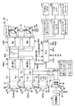
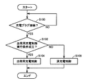
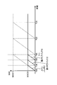
- FIG. 1 is an overall block diagram of a hybrid vehicle equipped with a vehicle control device according to the present embodiment. It is a timing chart which shows the change of SOC in the case of charging until all the batteries are fully charged using an external power supply. It is a functional block diagram of ECU which is a control device for vehicles concerning this embodiment. It is a flowchart which shows the control structure of the program performed by ECU which is the vehicle control apparatus which concerns on this Embodiment. It is a timing chart which shows operation
- vehicle 100 includes a first motor generator (hereinafter referred to as MG) 2, a second MG 4, a first inverter 12, a second inverter 14, a smoothing capacitor 16, and a first booster.
- Converter 22 second boost converter 24, first system main relay (hereinafter referred to as SMR) 32, second SMR 34, third SMR 36, main battery 42, first sub battery 44, and second sub
- SMR system main relay
- the battery 46, the charging device 50, the power split device 52, the driving wheel 54, the engine 56, the braking device 58, and an ECU (Electronic Control Unit) 200 are included.
- the vehicle 100 is described as being a hybrid vehicle.
- the vehicle 100 is not particularly limited to a hybrid vehicle, and may be any vehicle that uses at least a rotating electric machine as a drive source. Therefore, vehicle 100 may be an electric vehicle.
- the first MG2, the second MG4, and the engine 56 are connected to the power split device 52.
- the vehicle 100 travels by driving force from at least one of the engine 56 and the second MG 4.
- the power generated by the engine 56 is divided into two paths by the power split device 52. One is a path transmitted to the drive wheel 54, and the other is a path transmitted to the first MG2.
- the driving wheel 54 is provided with a braking device 58, and the braking device 58 limits the rotation of the driving wheel 54 when a brake pedal 112 described later is depressed.
- Each of the first MG2 and the second MG4 is an AC rotating electric machine, for example, a three-phase AC rotating electric machine including a rotor in which a permanent magnet is embedded.
- First MG 2 generates power using the power of engine 56 divided by power split device 52. For example, when the SOC (State of Charge) indicating the remaining capacity of the main battery 42 becomes lower than a predetermined value, the engine 56 is started and power is generated by the first MG 2, and the generated power is used as the main battery 42. To be supplied. The main battery 42 is charged with the electric power generated by the first MG2.
- SOC State of Charge
- the second MG 4 generates a driving force using the power supplied from the second inverter 14.
- the driving force of the second MG 4 is transmitted to the driving wheel 54.
- the second MG 4 is driven by the drive wheels 54, and the second MG 4 operates as a generator.
- the second MG 4 operates as a regenerative brake that converts braking energy into electric power.
- the electric power generated by the second MG 4 is supplied to the second inverter.
- the power supplied to the second inverter is supplied to the main battery 42 via the first boost converter 22 or to the first sub-battery 44 or the second sub-battery 46 via the second boost converter 24. Or be supplied.
- the main battery 42, the first sub-battery 44 or the second sub-battery 46 is charged by the electric power generated by the second MG 4.
- the power split device 52 is a planetary gear including a sun gear, a pinion gear, a carrier, and a ring gear (all not shown).
- the pinion gear engages with the sun gear and the ring gear.
- the carrier supports the pinion gear so as to be capable of rotating, and is connected to the crankshaft of the engine 56.
- the sun gear is connected to the rotation shaft of the first MG2.
- the ring gear is connected to the rotation shaft of the second MG 4.
- the first inverter 12 and the second inverter 14 are connected in parallel to the main positive bus MPL and the main negative bus MNL.
- First inverter 12 converts DC power supplied from first boost converter 22 or second boost converter 24 into AC power and outputs the AC power to first MG 2.
- Second inverter 14 converts the DC current supplied from first boost converter 22 or second boost converter 24 into AC power and outputs the AC power to second MG 4.
- first inverter 12 converts AC power generated in the first MG 2 into DC power and outputs the DC power to the first boost converter 22 or the second boost converter 24.
- Second inverter 14 converts AC power generated in second MG 4 into DC power and outputs the DC power to first boost converter 22 or second boost converter 24.
- Each of the first inverter 12 and the second inverter 14 is composed of a bridge circuit including switching elements for three phases, for example.
- First inverter 12 drives first MG2 by performing a switching operation in accordance with control signal PWI1 from ECU 200.
- Second inverter 14 drives second MG 4 by performing a switching operation in accordance with control signal PWI 2 from ECU 200.
- the ECU 200 is connected to a brake pedal position sensor 110, an accelerator pedal position sensor 114, a shift position sensor 118, and a steering position sensor 122.
- the brake pedal position sensor 110 detects the amount of operation of the brake pedal 112 (ie, the amount of depression).
- the brake pedal position sensor 110 transmits a signal indicating the detected depression amount of the brake pedal 112 to the ECU 200.
- a switch for detecting whether the brake pedal 112 is depressed (on state) or released (deactivated state) may be used. .
- the accelerator pedal position sensor 114 detects the operation amount (that is, the depression amount) of the accelerator pedal 116.
- the accelerator pedal position sensor 114 transmits a signal indicating the detected depression amount of the accelerator pedal 116 to the ECU 200.
- the shift position sensor 118 detects the position of the shift lever 120. Shift position sensor 118 transmits a signal indicating the detected position of shift lever 120 to ECU 200. ECU 200 identifies the currently selected shift position based on the received position of shift lever 120.
- the steering position sensor 122 detects the operation amount (that is, the rotation amount) of the steering wheel 124.
- the steering position sensor 122 transmits a signal indicating the amount of rotation of the steering wheel 124 to the ECU 200.
- the ECU 200 calculates the vehicle required power Ps based on the depression amount of the brake pedal 112, the depression amount of the accelerator pedal 116, the detection signal of each sensor (not shown), the traveling state, and the like, and based on the calculated vehicle required power Ps. Torque target values and rotation speed target values of 1MG2 and second MG4 are calculated. ECU 200 controls first inverter 12 and second inverter 14 such that the generated torque and rotation speed of first MG2 and second MG4 become target values.
- Each of the main battery 42, the first sub-battery 44, and the second sub-battery 46 is a rechargeable DC power source, for example, a secondary battery such as a nickel metal hydride battery or a lithium ion battery, a large capacity capacitor, or the like. .
- the main battery 42 is connected to the first boost converter 22 via the first SMR 32.
- the first sub-battery 44 is connected to the second boost converter 24 via the second SMR 34.
- Second sub-battery 46 is connected to second boost converter 24 via third SMR 36.
- the first sub battery 44 and the second sub battery 46 are mounted in addition to the main battery 42.
- First SMR 32 is electrically connected to main battery 42 and first boost converter 22, and electrically disconnects main battery 42 and first boost converter 22 based on control signal S ⁇ b> 1 from ECU 200. Switching from one of the shut-off states to the other state.
- second SMR 34 electrically connects first sub-battery 44 and second boost converter 24, and electrically connects first sub-battery 44 and second boost converter 24.
- the state is switched from one of the shut-off states to be shut off to the other.
- third SMR 36 electrically connects second sub-battery 46 and second boost converter 24, and electrically connects second sub-battery 46 and second boost converter 24.
- the state is switched from one of the shut-off states to be shut off to the other.
- ECU 200 transmits control signals S2 and S3 to first SMR 34 and third SMR 36 so that one of second SMR 34 and third SMR 36 is in a conducting state and the other is in a blocking state.
- the first sub-battery 44 and the second boost converter 24 are electrically connected. Therefore, the electric power of the first sub battery 44 is supplied to the second boost converter 24.
- the third SMR 36 becomes conductive and the second SMR 34 becomes cut-off, the second sub-battery 46 and the second boost converter 24 are electrically connected. Therefore, the electric power of the second sub battery 46 is supplied to the second boost converter 24.
- the second SMR 34 and the third SMR 36 are controlled to select a power source that supplies power to the second boost converter 24.
- the first boost converter 22 and the second boost converter 24 are connected in parallel to the main positive bus MPL and the main negative bus MNL.
- First boost converter 22 performs voltage conversion between main battery 42 and main positive bus MPL and main negative bus MNL based on control signal PWC1 from ECU 200.
- Second boost converter 24 performs voltage conversion between one of first sub-battery 44 and second sub-battery 46 and main positive bus MPL and main negative bus MNL based on control signal PWC2 from ECU 200.
- Smoothing capacitor 16 is connected between main positive bus MPL and main negative bus MNL, and reduces power fluctuation components included in main positive bus MPL and main negative bus MNL.
- the ECU 200 is further connected with a first current sensor 84, a first voltage sensor 86, a second current sensor 88, a second voltage sensor 90, a third current sensor 92, and a third voltage sensor 94. .
- the first current sensor 84 detects the current IB1 from the main battery 42 to the first boost converter 22, and transmits a signal indicating the detected current IB1 to the ECU 200.
- First voltage sensor 86 detects voltage VB1 of main battery 42, and transmits a signal indicating detected voltage VB1 to ECU 200.
- ECU 200 calculates the SOC of main battery 42 based on current IB1 detected by first current sensor 84 and voltage VB1 detected by first voltage sensor 86. ECU 200 may calculate the SOC of main battery 42 based on the temperature of main battery 42 in addition to current IB1 and voltage VB1. The temperature of the main battery 42 is detected by a temperature sensor (not shown) provided on the main battery 42. Further, the ECU 200 may calculate the SOC of the main battery 42 based on, for example, OCV (Open Circuit Voltage), or calculate the SOC of the main battery 42 based on the charging current and the discharging current. You may do it.
- OCV Open Circuit Voltage
- the second voltage sensor 90 detects the voltage VB2 of the first sub-battery 44 and transmits a signal indicating the detected voltage VB2 to the ECU 200.
- Second current sensor 92 detects current IB2 from first sub-battery 44 to second boost converter 24, and transmits a signal indicating detected current IB2 to ECU 200.
- ECU 200 calculates the SOC of first sub-battery 44 based on current IB2 detected by second current sensor 88 and voltage VB2 detected by second voltage sensor 90. ECU 200 may calculate the SOC of first sub-battery 44 based on the temperature of first sub-battery 44 in addition to current IB2 and voltage VB2. Since the SOC calculation method is as described above, detailed description thereof will not be repeated.
- the third voltage sensor 94 detects the voltage VB3 of the second sub-battery 46 and transmits a signal indicating the detected voltage VB3 to the ECU 200.
- Third current sensor 92 detects current IB3 from second sub-battery 46 to second boost converter 24, and transmits a signal indicating detected current IB3 to ECU 200.
- ECU 200 calculates the SOC of second sub-battery 46 based on current IB3 detected by third current sensor 92 and voltage VB3 detected by third voltage sensor 94. ECU 200 may calculate the SOC of second sub-battery 46 based on the temperature of second sub-battery 46 in addition to current IB3 and voltage VB3. Since the SCO calculation method is as described above, detailed description thereof will not be repeated.
- the first current sensor 84, the second current sensor 88, and the third current sensor 92 have been described as detecting the positive line current, but the present invention is not particularly limited thereto.
- the current of the negative electrode wire may be detected.
- the ECU 200 generates control signals S2 and S3 for sequentially switching and using the first sub-battery 44 and the second sub-battery 46, and transmits them to the second SMR 34 and the third SMR 36.
- the ECU 200 electrically connects the first sub battery 44 and the second boost converter 24 to each other.
- Control signals S2 and S3 are generated so that the second SMR 34 in the conductive state is in the cut-off state and the third SMR 36 in the cut-off state is in the conductive state when the SOC of the battery is lower than the SOC indicating the predetermined remaining capacity. To do.
- ECU 200 generates control signal PWC1 for controlling first boost converter 22 and control signal PWC2 for controlling second boost converter 24 based on vehicle required power Ps. ECU 200 transmits the generated control signals PWC1 and PWC2 to first boost converter 22 and second boost converter 24, respectively, and controls first boost converter 22 and second boost converter 24.
- the charging device 50 is attached with a charging plug 62 connected to the external power source 60, and uses any one of the main battery 42, the first sub battery 44, and the second sub battery 46 using the power of the external power source 60. To charge.
- the charging plug 62 includes a lock mechanism that locks the connection between the charging device 50 and the charging plug 62 when the connection between the charging device 50 and the charging plug 62 is completed, and an initial position when the operation of the locking mechanism is completed. And a button 68 for moving to a predetermined position. The user confirms that the lock mechanism is operating normally by moving the button 68 from the initial position to a predetermined position, and that the connection between the charging device 50 and the charging plug 62 has been completed. Can be recognized. When the user moves the position of the button 68 from the predetermined position to the initial position, the lock of the connection between the charging device 50 and the charging plug 62 by the lock mechanism is released. At this time, the user can remove the charging plug 62 from the charging device 50.
- the switch 68 is attached to the button 68.
- the switch 64 When the position of the button 68 is moved from the initial position to a predetermined position, the switch 64 outputs a signal PI indicating that the button 68 has been operated. It transmits to ECU200 via the charging device 50.
- the switch 64 stops transmission of the signal PI when the position of the button 68 is moved from a predetermined position to an initial position.
- the switch 64 transmits a signal PI to the ECU 200 when the position of the button 68 is moved from a predetermined position to an initial position, and when the position of the button 68 is moved from the initial position to a predetermined position. The transmission of the signal PI may be stopped.
- the charging device 50 is provided with a connection confirmation sensor 66 for detecting that the charging plug 62 and the charging device 50 are connected.
- the connection confirmation sensor 66 is an electric circuit that conducts when the charging plug 62 and the charging device 50 are connected. Connection confirmation sensor 66 transmits to ECU 200 a signal C1 indicating that charging plug 62 and charging device 50 are connected.
- the external power source 60 is a power source provided outside the vehicle 100, and may be an AC power source such as a commercial power source, for example.
- the charging device 50 is connected in parallel to each of the first sub battery 44 and the second sub battery 46 via a relay 38.
- Relay 38 is electrically connected to charging device 50 and first sub-battery 44 or second sub-battery 46 in accordance with control signal S4 from ECU 200, charging device 50 and first sub-battery 44 or Switching from any one of the shut-off states in which the second sub-battery 46 is electrically shut off to the other.
- vehicle 100 having the above configuration, when main battery 42, first sub-battery 44, and second sub-battery 46 mounted on vehicle 100 are charged using external power source 60 until they are fully charged. There is a possibility that the battery is left in a fully charged state after the charging is completed. For example, when the user does not drive the vehicle 100 for a long time after charging, or when it takes a long time until it reaches the user after being shipped by transportation after being charged at the factory shipment stage of the vehicle 100, the fully charged state Since the battery is left for a long time, deterioration of the battery may be accelerated.
- the factory shipment stage is a stage where the vehicle 100 is manufactured from the factory and then shipped from the factory.
- the main battery Charging is started so that the SOC of 42 becomes SOC (1) which is the upper limit value of the SOC corresponding to the fully charged state.
- the vertical axis in FIG. 2 indicates the SOC, and the horizontal axis in FIG. 2 indicates the time.
- ECU 200 when external power supply 60 and charging device 50 are connected, ECU 200 causes the SOCs of main battery 42, first sub battery 44, and second sub battery 46 to be SOC (1).
- the second charge control is performed instead of the first charge control.
- the second charge control is a charge control executed when the vehicle 100 is shipped from the factory, and the main battery 42, the first sub battery 44, and the second sub battery 46 are used using the external power source 60. Charge control for charging each of the SOCs until a threshold value for shipping SOC (2) lower than SOC (1) is reached.
- the first charge control is described as full charge control
- the second charge control is described as shipping charge control.
- the input unit is the brake pedal 110 and the brake pedal position sensor 112
- the ECU 200 includes the brake pedal position sensor in addition to the case where the external power source 60 and the charging device 50 are connected.
- Threshold SOC (2) is the charge amount of main battery 42, first sub battery 44, and second sub battery 46 corresponding to the time of shipment of vehicle 100.
- the threshold SOC (2) is, for example, power that can be moved and started the engine from when the vehicle 100 is shipped until it reaches the user, and a decrease in the remaining capacity during the storage period (for example, a decrease due to self-discharge) 1 or the amount of consumption when the system of the vehicle 100 is stopped).
- threshold SOC (2) is charged until a time necessary for checking whether main battery 42, first sub-battery 44, and second sub-battery 46 can be normally charged passes. Is the second charge amount charged.
- the threshold SOC (2) is the larger of the above-described first charge amount and second charge amount.
- FIG. 3 shows a functional block diagram of ECU 200 that is the vehicle control apparatus according to the present embodiment.
- ECU 200 includes a connection determination unit 300, an execution condition determination unit 302, a shipping charge control unit 304, and a full charge control unit 306.
- the connection determination unit 300 determines whether or not the charging plug 62 is connected to the charging device 50. Specifically, when the signal C1 indicating that the charging plug 62 is connected to the charging device 50 is received from the connection confirmation sensor 66, it is determined that the charging plug 62 is connected to the charging device 50. Note that the connection determination unit 300 may turn on the connection determination flag when it is determined that the charging plug 62 is connected to the charging device 50, for example.
- the execution condition determination unit 302 determines whether or not the execution condition for the shipping charge control is satisfied.
- the execution condition of the shipping charge control is a condition that a command for executing the shipping charge control is input to the input unit as described above, and specifically, the brake pedal 112 in a predetermined period. This is a condition that the number of times of repeating the stepping and releasing of the stepping is a predetermined number of times.
- the execution condition determination unit 302 determines, for example, whether the execution condition is satisfied when the connection determination flag is on, and turns on the execution condition determination flag when it is determined that the execution condition is satisfied. You may make it do. For example, the execution condition determination unit 302 determines whether or not the execution condition is satisfied until a predetermined time elapses after it is determined that the charging plug 62 is connected to the charging device 50. Alternatively, it is determined whether or not the execution condition is satisfied until an operation for starting charging using the external power source 60 is performed after it is determined that the charging plug 62 is connected to the charging device 50. You may make it determine.
- the shipping charge control unit 304 executes the shipping charge control when the execution condition determining unit 302 determines that the execution condition is satisfied. Specifically, shipping charge control unit 304 performs main processing until each SOC of main battery 42, first sub-battery 44, and second sub-battery 46 reaches the threshold SOC (2) for shipping SOC. The battery 42, the first sub battery 44, and the second sub battery 46 are charged.
- the threshold SOC (2) of the shipping SOC may be a value lower than the SOC (1) corresponding to the fully charged state, for example. Further, in the present embodiment, threshold SOC (2) of the SOC for shipping is described as being the same value in each of main battery 42, first sub-battery 44, and second sub-battery 46. However, the present invention is not particularly limited to this, and the main battery 42, the first sub battery 44, and the second sub battery 46 may have different values. For example, any of the main battery 42, the first sub-battery 44, and the second sub-battery 46 may have a threshold value that is higher than the threshold value of the other battery. In this way, it is possible to prevent an unnecessarily long charge time for a battery having a large charge capacity.
- the shipping charge control unit 304 charges the main battery 42 until the SOC of the main battery 42 reaches the threshold SOC (2) of the shipping SOC.
- the shipping charge control unit 304 maintains both the second SMR 34 and the third SMR 36 in the cut-off state, 1 SMR 32 is switched from the cutoff state to the conductive state.
- the shipping charge control unit 304 operates the first boost converter 22, the second boost converter 24, and the charging device 50, thereby passing the charging device 50, the second boost converter 24, and the first boost converter 22 from the external power source 60. Then, power is supplied to the main battery 42.
- the main battery 42 is charged by supplying power from the external power source 60 to the main battery 42.
- the shipping charge control unit 304 monitors the SOC of the main battery 42 based on the current IB1 and the voltage VB1, and when the SOC of the main battery 42 is equal to or higher than the threshold SOC (2) of the shipping SOC, The charging of the main battery 42 is completed. At this time, the shipping charge control unit 304 stops the operation of the first boost converter 22, the second boost converter 24, and the charging device 50, and switches the first SMR 32 from the conduction state to the cutoff state.
- the shipping charge control unit 304 charges the first sub-battery 44 until the SOC of the first sub-battery 44 reaches the threshold SOC (2) of the shipping SOC after the charging of the main battery 42 is completed.
- the shipping charge control unit 304 switches the second SMR 34 from the cutoff state to the conductive state while maintaining the first SMR 32 and the third SMR 36 both in the cutoff state.
- the shipping charge controller 304 supplies the first sub-battery 44 from the external power source 60 via the charging device 50 by operating the charging device 50. When power is supplied from the external power source 60 to the first sub battery 44, the first sub battery 44 is charged.
- the shipping charge control unit 304 monitors the SOC of the first sub-battery 44 based on the current IB2 and the voltage VB2, and the SOC of the first sub-battery 44 is equal to or higher than the threshold SOC (2) of the shipping SOC. If so, the charging of the first sub-battery 44 is completed. At this time, the shipping charge control unit 304 stops the operation of the charging device 50 and switches the second SMR 34 from the conduction state to the cutoff state.
- the shipping charge control unit 304 charges the second sub-battery 46 until the SOC of the second sub-battery 46 reaches the shipping SOC threshold SOC (2) after the charging of the first sub-battery 44 is completed.
- the shipping charge control unit 304 switches the third SMR 36 from the cut-off state to the conductive state while maintaining both the first SMR 32 and the second SMR 34 in the cut-off state.
- the shipping charge controller 304 supplies the second sub-battery 46 from the external power source 60 via the charging device 50 by operating the charging device 50. When power is supplied from the external power source 60 to the second sub battery 46, the second sub battery 46 is charged.
- the shipping charge control unit 304 monitors the SOC of the second sub-battery 46 based on the current IB3, the voltage VB3, and the like, and when the SOC of the second sub-battery 46 is equal to or higher than the threshold of the shipping SOC, The charging of the second sub battery 46 is completed. At this time, the shipping charge control unit 304 stops the operation of the charging device 50 and switches the third SMR 36 from the conduction state to the cutoff state.
- the shipping charge control unit 304 may execute the shipping charge control when, for example, both the connection determination flag and the execution condition determination flag are on.
- the shipping charge control unit 304 starts charging the first sub-battery 44 after the charging of the main battery 42 is completed, and after the charging of the first sub-battery 44 is completed, Although it has been described that charging of the two sub-batteries 46 is started, the order of charging is not particularly limited to such an order.
- the full charge control unit 306 performs full charge control when the execution condition determination unit 302 determines that the execution condition is not satisfied.
- full charge control differs from shipping charge control only in that the threshold for determining that charging is complete is the threshold SOC (1) corresponding to the full charge state.
- the other charging operation is the same as the charging operation in the shipping charge control. Therefore, detailed description thereof will not be repeated.
- connection determination unit 300 execution condition determination unit 302, shipping charge control unit 304, and full charge control unit 306 all execute a program stored in the memory of CPU of ECU 200.
- execution condition determination unit 302 execution condition determination unit 302
- shipping charge control unit 304 shipping charge control unit 304
- full charge control unit 306 all execute a program stored in the memory of CPU of ECU 200.
- a program is recorded on a storage medium and mounted on the vehicle.
- step (hereinafter, step is referred to as S) 100 ECU 200 determines whether or not charging plug 62 is connected. If it is determined that charging plug 62 is connected (YES in S100), the process proceeds to S102. If not (NO in S100), the process returns to S100.
- ECU 200 determines whether or not an execution condition for shipping charge control is satisfied. If it is determined that the execution condition for the shipping charge control is satisfied (YES in S102), the process proceeds to S104. If not (NO in S102), the process proceeds to S106.
- ECU 200 executes charge control for shipment.
- ECU 200 executes full charge control. Note that shipping charge control and full charge control are as described above, and thus detailed description thereof will not be repeated.
- ECU 200 that is the vehicle control apparatus according to the present embodiment based on the above-described structure and flowchart will be described with reference to FIG.
- the brake pedal 112 is depressed and released, and the predetermined time is determined in advance. If the execution condition is satisfied by performing the number of times (YES in S102), the charge control for shipping is executed at time T (0) (S104).
- a command for executing the second charge control in the input unit when the external power source and the charging device are connected is provided.
- the SOC of the main battery, the first sub-battery and the second sub-battery is set to a threshold SOC (2) lower than the upper limit SOC (1) of the SOC corresponding to the fully charged state using the external power source.
- the second charging control is not particularly limited to being executed when the vehicle 100 is shipped from the factory.
- the SOC of all the batteries is set to be higher than the upper limit SOC (1) of the SOC corresponding to the fully charged state when charging using the external power source. You may make it charge to low threshold value SOC (2).
- SOC (2) low threshold value
- different threshold SOCs (2) may be different between the shipping charge control and the charge control executed when the user leaves the vehicle 100 for a long time, or the execution conditions of both controls May be different.
- the number of operations of the button 68 of the charge plug 62 is set to be a predetermined number or more, and the charge control for allowing the user to leave the vehicle 100 for a long time is performed by operating the brake pedal 112.
- the number of times may be a predetermined number or more as an execution condition. Since the threshold values for the charge control for shipping and the threshold values for the charge control for leaving the vehicle 100 for a long time are as described above, detailed description thereof will not be repeated.
- the input unit has been described as including the brake pedal position sensor 110 and the brake pedal 112, but the input unit is not particularly limited thereto.
- the input unit includes a button 68 of the charging plug 62 and a switch 64, and the ECU 200 is a case where the external power source 60 and the charging device 50 are connected, and the switch 64 is in a predetermined period.
- the second charging control may be executed when the number of times of repeating ON and OFF (the number of times of receiving the PI signal) is a predetermined number.
- the input unit may include an operation member such as a button of the air conditioner, the navigation system, and the audio system, and a switch that detects whether the button is pressed and transmits a signal indicating the detection result to the ECU 200. Good.
- an operation member such as a button of the air conditioner, the navigation system, and the audio system
- the input unit may include an accelerator pedal position sensor 114 and an accelerator pedal 116, a shift position sensor 118, and a shift lever 120, a steering position sensor 122, and a steering wheel. 124 may be included.
- the configuration of the vehicle 100 is not particularly limited to the configuration shown in FIG. 1, and may be, for example, the configuration shown in FIG.
- the vehicle 100 shown in FIG. 6 is different from the configuration of the vehicle 100 shown in FIG. 1 in that the charging device 50 is connected in parallel to the first boost converter, the relay 38, and the second sub-battery. 46, the third SMR 36 is not provided. Since the configuration other than that is similar to the configuration of vehicle 100 shown in FIG. 1, detailed description thereof will not be repeated.
- the first SMR 32 is switched from the cut-off state to the conductive state, the charging device 50 is activated, the cut-off state of the second SMR 32 is maintained, and the first boost converter 22 is maintained. The state where the operation of the second boost converter 24 is stopped is maintained.
- the first SMR 32 is switched from the conductive state to the cut-off state, and the operation of the charging device 50 is stopped.
- the second SMR 34 is switched from the cut-off state to the conductive state, and the first boost converter 22, the second boost converter 24, and the charging device 50 are operated, and the cut-off state of the first SMR 32 is maintained. Is done.
- the second SMR 34 is switched from the conductive state to the cut-off state, and the operations of the first boost converter 22, the second boost converter 24, and the charging device 50 are stopped.
- ECU 200 switches both first SMR 32 and second SMR 34 from the cut-off state to the conductive state, and operates first boost converter 22, second boost converter 24, and charging device 50.
- first boost converter 22 and the first sub battery 44 may be charged simultaneously.
Landscapes
- Engineering & Computer Science (AREA)
- Power Engineering (AREA)
- Transportation (AREA)
- Mechanical Engineering (AREA)
- Life Sciences & Earth Sciences (AREA)
- Sustainable Development (AREA)
- Sustainable Energy (AREA)
- Manufacturing & Machinery (AREA)
- Chemical & Material Sciences (AREA)
- Chemical Kinetics & Catalysis (AREA)
- Electrochemistry (AREA)
- General Chemical & Material Sciences (AREA)
- Electric Propulsion And Braking For Vehicles (AREA)
- Charge And Discharge Circuits For Batteries Or The Like (AREA)
- Secondary Cells (AREA)
- Battery Mounting, Suspending (AREA)
Priority Applications (5)
| Application Number | Priority Date | Filing Date | Title |
|---|---|---|---|
| EP10853640.0A EP2596981B1 (de) | 2010-06-23 | 2010-06-23 | Steuerungsvorrichtung für fahrzeug und steuerungsverfahren für fahrzeug |
| US13/702,937 US9511679B2 (en) | 2010-06-23 | 2010-06-23 | Vehicular control device and method |
| PCT/JP2010/060647 WO2011161780A1 (ja) | 2010-06-23 | 2010-06-23 | 車両用制御装置および車両用制御方法 |
| CN201080068683.4A CN103079869B (zh) | 2010-06-23 | 2010-06-23 | 车辆用控制装置及车辆用控制方法 |
| JP2012521213A JP5621845B2 (ja) | 2010-06-23 | 2010-06-23 | 車両用制御装置および車両用制御方法 |
Applications Claiming Priority (1)
| Application Number | Priority Date | Filing Date | Title |
|---|---|---|---|
| PCT/JP2010/060647 WO2011161780A1 (ja) | 2010-06-23 | 2010-06-23 | 車両用制御装置および車両用制御方法 |
Publications (1)
| Publication Number | Publication Date |
|---|---|
| WO2011161780A1 true WO2011161780A1 (ja) | 2011-12-29 |
Family
ID=45370993
Family Applications (1)
| Application Number | Title | Priority Date | Filing Date |
|---|---|---|---|
| PCT/JP2010/060647 WO2011161780A1 (ja) | 2010-06-23 | 2010-06-23 | 車両用制御装置および車両用制御方法 |
Country Status (5)
| Country | Link |
|---|---|
| US (1) | US9511679B2 (de) |
| EP (1) | EP2596981B1 (de) |
| JP (1) | JP5621845B2 (de) |
| CN (1) | CN103079869B (de) |
| WO (1) | WO2011161780A1 (de) |
Cited By (5)
| Publication number | Priority date | Publication date | Assignee | Title |
|---|---|---|---|---|
| JP2014023222A (ja) * | 2012-07-13 | 2014-02-03 | Toshiba Corp | 蓄電池装置の制御方法、蓄電池装置、および、蓄電池システム |
| JP2014121888A (ja) * | 2012-12-20 | 2014-07-03 | Mitsubishi Motors Corp | ペダルによる決定操作装置 |
| JP2016101800A (ja) * | 2014-11-27 | 2016-06-02 | マツダ株式会社 | 車両用電源制御装置 |
| WO2017094431A1 (ja) * | 2015-12-01 | 2017-06-08 | オムロン株式会社 | バッテリ充電装置、バッテリ充電システムおよびバッテリ充電方法 |
| CN107380157A (zh) * | 2016-05-16 | 2017-11-24 | 福特全球技术公司 | 混合动力电动车辆发动机起动 |
Families Citing this family (14)
| Publication number | Priority date | Publication date | Assignee | Title |
|---|---|---|---|---|
| DE102013008420A1 (de) * | 2013-05-17 | 2014-11-20 | Abb Technology Ag | Antriebseinheit zur Ansteuerung eines Motors |
| US9455582B2 (en) | 2014-03-07 | 2016-09-27 | Apple Inc. | Electronic device and charging device for electronic device |
| JP6193475B2 (ja) * | 2014-03-27 | 2017-09-06 | 本田技研工業株式会社 | 車両給電方法 |
| US9917335B2 (en) | 2014-08-28 | 2018-03-13 | Apple Inc. | Methods for determining and controlling battery expansion |
| US20160064961A1 (en) * | 2014-09-02 | 2016-03-03 | Apple Inc. | User-behavior-driven battery charging |
| FR3028109B1 (fr) * | 2014-11-03 | 2020-01-24 | Renault S.A.S | Procede de gestion de l'etat de charge d'une batterie de traction d'un vehicule hybride. |
| KR101736475B1 (ko) * | 2015-02-04 | 2017-05-16 | 한화테크윈 주식회사 | 전기 차량 |
| JP6525146B2 (ja) * | 2015-04-24 | 2019-06-05 | 三菱自動車工業株式会社 | シフト制御装置 |
| CN107921919B (zh) * | 2015-05-22 | 2019-04-05 | 日产自动车株式会社 | 电源系统控制装置以及电源系统控制方法 |
| US11218006B2 (en) * | 2017-04-13 | 2022-01-04 | Enphase Energy, Inc. | Method and system for an AC battery |
| US20200395774A1 (en) * | 2019-06-17 | 2020-12-17 | Renesas Electronics America Inc. | Single inductor multiple output charger for multiple battery applications |
| JP2021035121A (ja) * | 2019-08-21 | 2021-03-01 | 株式会社デンソー | 電力制御装置 |
| CN111422073B (zh) * | 2020-04-09 | 2021-12-03 | 宁波吉利汽车研究开发有限公司 | 一种用于新能源车辆的电池充放电功率限制方法及系统 |
| US11613184B1 (en) * | 2021-10-31 | 2023-03-28 | Beta Air, Llc | Systems and methods for disabling an electric vehicle during charging |
Citations (9)
| Publication number | Priority date | Publication date | Assignee | Title |
|---|---|---|---|---|
| JP2002247710A (ja) * | 2000-12-14 | 2002-08-30 | Nissan Motor Co Ltd | 車両共同利用システムの車両管理装置および車両管理方法 |
| JP2005335498A (ja) * | 2004-05-26 | 2005-12-08 | Auto Network Gijutsu Kenkyusho:Kk | 車両電源制御装置 |
| JP2006125351A (ja) * | 2004-11-01 | 2006-05-18 | Fujitsu Ten Ltd | エンジン始動制御装置及びエンジン始動制御方法 |
| JP2006304393A (ja) | 2005-04-15 | 2006-11-02 | Toyota Motor Corp | 電源装置およびその制御方法並びに車両 |
| JP2006325317A (ja) * | 2005-05-18 | 2006-11-30 | Nissan Motor Co Ltd | 充電装置 |
| JP2009033785A (ja) * | 2007-07-24 | 2009-02-12 | Toyota Motor Corp | 電源システムおよびそれを備えた電動車両ならびに電源システムの制御方法 |
| JP2009137456A (ja) * | 2007-12-06 | 2009-06-25 | Toyota Motor Corp | 充電制御装置 |
| JP2009247057A (ja) * | 2008-03-28 | 2009-10-22 | Fuji Heavy Ind Ltd | 電気自動車の制御装置 |
| JP2009254221A (ja) * | 2008-04-11 | 2009-10-29 | Kansai Electric Power Co Inc:The | 二次電池の充電方法 |
Family Cites Families (22)
| Publication number | Priority date | Publication date | Assignee | Title |
|---|---|---|---|---|
| KR100471551B1 (ko) * | 1996-05-24 | 2005-04-14 | 히노지도샤코교 가부시기가이샤 | 차재전지의제어장치 |
| DE19952165C2 (de) * | 1999-10-29 | 2003-05-08 | Techem Service Ag | Regelverfahren und Regler für elektrisch betriebene Stelleinrichtungen |
| DE20022539U1 (de) * | 1999-10-29 | 2001-10-25 | Techem Service Ag | Regler für elektrisch betriebene Stelleinrichtungen |
| JP2002280080A (ja) | 2001-03-16 | 2002-09-27 | Sony Corp | 二次電池の充電方法 |
| JP3812459B2 (ja) * | 2002-02-26 | 2006-08-23 | トヨタ自動車株式会社 | 車両の電源制御装置 |
| JP3820184B2 (ja) * | 2002-05-30 | 2006-09-13 | 松下電器産業株式会社 | 二次電池の交換方法 |
| DE10224808A1 (de) * | 2002-06-05 | 2003-12-18 | Aloys Wobben | Verfahren zum Transportieren elektrischer Energie |
| JP4281725B2 (ja) * | 2005-09-01 | 2009-06-17 | トヨタ自動車株式会社 | ハイブリッド自動車 |
| JP4869748B2 (ja) | 2006-03-14 | 2012-02-08 | 日東電工株式会社 | ガラス保護用粘着シートおよび自動車ガラス用保護フィルム |
| JP4747996B2 (ja) | 2006-08-21 | 2011-08-17 | 株式会社デンソー | 車両用無線キー、及び車両ドア遠隔施解錠制御システム |
| JP2008054442A (ja) * | 2006-08-25 | 2008-03-06 | Honda Motor Co Ltd | 小型電動車両 |
| JP4905300B2 (ja) * | 2006-09-28 | 2012-03-28 | トヨタ自動車株式会社 | 電源システムおよびそれを備えた車両、電源システムの制御方法ならびにその制御方法をコンピュータに実行させるためのプログラムを記録したコンピュータ読取可能な記録媒体 |
| US8030880B2 (en) * | 2006-11-15 | 2011-10-04 | Glacier Bay, Inc. | Power generation and battery management systems |
| US7746026B2 (en) * | 2006-12-22 | 2010-06-29 | Chrysler Group Llc | Controlling state of charge of a vehicle battery |
| US8912753B2 (en) * | 2007-10-04 | 2014-12-16 | General Motors Llc. | Remote power usage management for plug-in vehicles |
| JP4715881B2 (ja) * | 2008-07-25 | 2011-07-06 | トヨタ自動車株式会社 | 電源システムおよびそれを備えた車両 |
| JP4655124B2 (ja) * | 2008-08-25 | 2011-03-23 | トヨタ自動車株式会社 | ハイブリッド車両の制御装置 |
| JP4623181B2 (ja) * | 2008-09-24 | 2011-02-02 | トヨタ自動車株式会社 | 電動車両および充電制御システム |
| US20110258112A1 (en) * | 2008-10-31 | 2011-10-20 | Leviton Manufacturing Company Inc. | System and method for charging a vehicle |
| CN102246386B (zh) * | 2008-12-09 | 2014-06-11 | 丰田自动车株式会社 | 车辆的电源系统 |
| US20100274570A1 (en) * | 2009-04-24 | 2010-10-28 | Gm Global Technology Operations, Inc. | Vehicle charging authorization |
| US8820444B2 (en) * | 2010-04-16 | 2014-09-02 | Tuan Nguyen | Electric vehicle having exchangeable battery modules and method of resupply therefor |
-
2010
- 2010-06-23 EP EP10853640.0A patent/EP2596981B1/de active Active
- 2010-06-23 US US13/702,937 patent/US9511679B2/en active Active
- 2010-06-23 JP JP2012521213A patent/JP5621845B2/ja active Active
- 2010-06-23 WO PCT/JP2010/060647 patent/WO2011161780A1/ja active Application Filing
- 2010-06-23 CN CN201080068683.4A patent/CN103079869B/zh active Active
Patent Citations (9)
| Publication number | Priority date | Publication date | Assignee | Title |
|---|---|---|---|---|
| JP2002247710A (ja) * | 2000-12-14 | 2002-08-30 | Nissan Motor Co Ltd | 車両共同利用システムの車両管理装置および車両管理方法 |
| JP2005335498A (ja) * | 2004-05-26 | 2005-12-08 | Auto Network Gijutsu Kenkyusho:Kk | 車両電源制御装置 |
| JP2006125351A (ja) * | 2004-11-01 | 2006-05-18 | Fujitsu Ten Ltd | エンジン始動制御装置及びエンジン始動制御方法 |
| JP2006304393A (ja) | 2005-04-15 | 2006-11-02 | Toyota Motor Corp | 電源装置およびその制御方法並びに車両 |
| JP2006325317A (ja) * | 2005-05-18 | 2006-11-30 | Nissan Motor Co Ltd | 充電装置 |
| JP2009033785A (ja) * | 2007-07-24 | 2009-02-12 | Toyota Motor Corp | 電源システムおよびそれを備えた電動車両ならびに電源システムの制御方法 |
| JP2009137456A (ja) * | 2007-12-06 | 2009-06-25 | Toyota Motor Corp | 充電制御装置 |
| JP2009247057A (ja) * | 2008-03-28 | 2009-10-22 | Fuji Heavy Ind Ltd | 電気自動車の制御装置 |
| JP2009254221A (ja) * | 2008-04-11 | 2009-10-29 | Kansai Electric Power Co Inc:The | 二次電池の充電方法 |
Non-Patent Citations (1)
| Title |
|---|
| See also references of EP2596981A4 |
Cited By (7)
| Publication number | Priority date | Publication date | Assignee | Title |
|---|---|---|---|---|
| JP2014023222A (ja) * | 2012-07-13 | 2014-02-03 | Toshiba Corp | 蓄電池装置の制御方法、蓄電池装置、および、蓄電池システム |
| JP2014121888A (ja) * | 2012-12-20 | 2014-07-03 | Mitsubishi Motors Corp | ペダルによる決定操作装置 |
| JP2016101800A (ja) * | 2014-11-27 | 2016-06-02 | マツダ株式会社 | 車両用電源制御装置 |
| WO2017094431A1 (ja) * | 2015-12-01 | 2017-06-08 | オムロン株式会社 | バッテリ充電装置、バッテリ充電システムおよびバッテリ充電方法 |
| JP2017103897A (ja) * | 2015-12-01 | 2017-06-08 | オムロン株式会社 | バッテリ充電装置、バッテリ充電システムおよびバッテリ充電方法 |
| US10688876B2 (en) | 2015-12-01 | 2020-06-23 | Omron Corporation | Battery charging device, battery charging system, and battery charging method |
| CN107380157A (zh) * | 2016-05-16 | 2017-11-24 | 福特全球技术公司 | 混合动力电动车辆发动机起动 |
Also Published As
| Publication number | Publication date |
|---|---|
| JPWO2011161780A1 (ja) | 2013-08-19 |
| JP5621845B2 (ja) | 2014-11-12 |
| EP2596981A1 (de) | 2013-05-29 |
| US9511679B2 (en) | 2016-12-06 |
| CN103079869A (zh) | 2013-05-01 |
| US20130090797A1 (en) | 2013-04-11 |
| CN103079869B (zh) | 2015-06-10 |
| EP2596981B1 (de) | 2019-05-22 |
| EP2596981A4 (de) | 2017-04-05 |
Similar Documents
| Publication | Publication Date | Title |
|---|---|---|
| JP5621845B2 (ja) | 車両用制御装置および車両用制御方法 | |
| JP4788842B2 (ja) | ハイブリッド車両の制御装置および制御方法 | |
| US9233613B2 (en) | Electrically powered vehicle and method for controlling electrically powered vehicle | |
| EP2353920B1 (de) | Elektrisch angetriebenes fahrzeug und verfahren zur steuerung eines elektrisch angetriebenen fahrzeugs | |
| EP2669131B1 (de) | Hybridfahrzeug | |
| JP6003943B2 (ja) | ハイブリッド車両およびハイブリッド車両の制御方法 | |
| WO2011016135A1 (ja) | 電動車両の電源システム | |
| WO2011024285A1 (ja) | 車両の電源システムおよびそれを備える電動車両 | |
| JP5413507B2 (ja) | 車両用制御装置および車両用制御方法 | |
| KR101761539B1 (ko) | 하이브리드 차량 | |
| EP2403103B1 (de) | Steuervorrichtung und verfahren für ein fahrzeug | |
| WO2012131864A1 (ja) | 電動車両およびその制御方法 | |
| US20110068740A1 (en) | Power supply system for vehicle, electric vehicle having the same, and method of controlling power supply system for vehicle | |
| JP2010104114A (ja) | 車両の制御装置および車両 | |
| JP5556636B2 (ja) | 電気自動車およびその異常判定方法 | |
| JP5675561B2 (ja) | 電気自動車 | |
| JP5625715B2 (ja) | 車両の制御装置および制御方法 | |
| JP5885236B2 (ja) | 車両の電源装置 | |
| JP5293160B2 (ja) | 車両の制御装置 | |
| JP2012046120A (ja) | ハイブリッド車の発電制御装置 | |
| JP2010089719A (ja) | ハイブリッド車両の電源システム | |
| JP2015013517A (ja) | 車両の制御装置 | |
| JP2019087423A (ja) | 電池システム | |
| WO2014038442A1 (ja) | ハイブリッド車両の制御装置 |
Legal Events
| Date | Code | Title | Description |
|---|---|---|---|
| WWE | Wipo information: entry into national phase |
Ref document number: 201080068683.4 Country of ref document: CN |
|
| 121 | Ep: the epo has been informed by wipo that ep was designated in this application |
Ref document number: 10853640 Country of ref document: EP Kind code of ref document: A1 |
|
| DPE2 | Request for preliminary examination filed before expiration of 19th month from priority date (pct application filed from 20040101) | ||
| WWE | Wipo information: entry into national phase |
Ref document number: 13702937 Country of ref document: US |
|
| WWE | Wipo information: entry into national phase |
Ref document number: 2012521213 Country of ref document: JP |
|
| NENP | Non-entry into the national phase |
Ref country code: DE |
|
| WWE | Wipo information: entry into national phase |
Ref document number: 2010853640 Country of ref document: EP |