WO2011151928A1 - 助手席用エアバッグ - Google Patents
助手席用エアバッグ Download PDFInfo
- Publication number
- WO2011151928A1 WO2011151928A1 PCT/JP2010/059565 JP2010059565W WO2011151928A1 WO 2011151928 A1 WO2011151928 A1 WO 2011151928A1 JP 2010059565 W JP2010059565 W JP 2010059565W WO 2011151928 A1 WO2011151928 A1 WO 2011151928A1
- Authority
- WO
- WIPO (PCT)
- Prior art keywords
- width direction
- vehicle width
- vehicle
- panel
- passenger
- Prior art date
- Legal status (The legal status is an assumption and is not a legal conclusion. Google has not performed a legal analysis and makes no representation as to the accuracy of the status listed.)
- Ceased
Links
Images




Classifications
-
- B—PERFORMING OPERATIONS; TRANSPORTING
- B60—VEHICLES IN GENERAL
- B60R—VEHICLES, VEHICLE FITTINGS, OR VEHICLE PARTS, NOT OTHERWISE PROVIDED FOR
- B60R21/00—Arrangements or fittings on vehicles for protecting or preventing injuries to occupants or pedestrians in case of accidents or other traffic risks
- B60R21/02—Occupant safety arrangements or fittings, e.g. crash pads
- B60R21/16—Inflatable occupant restraints or confinements designed to inflate upon impact or impending impact, e.g. air bags
- B60R21/23—Inflatable members
- B60R21/235—Inflatable members characterised by their material
-
- B—PERFORMING OPERATIONS; TRANSPORTING
- B60—VEHICLES IN GENERAL
- B60R—VEHICLES, VEHICLE FITTINGS, OR VEHICLE PARTS, NOT OTHERWISE PROVIDED FOR
- B60R21/00—Arrangements or fittings on vehicles for protecting or preventing injuries to occupants or pedestrians in case of accidents or other traffic risks
- B60R21/02—Occupant safety arrangements or fittings, e.g. crash pads
- B60R21/16—Inflatable occupant restraints or confinements designed to inflate upon impact or impending impact, e.g. air bags
- B60R21/23—Inflatable members
- B60R21/231—Inflatable members characterised by their shape, construction or spatial configuration
-
- B—PERFORMING OPERATIONS; TRANSPORTING
- B60—VEHICLES IN GENERAL
- B60R—VEHICLES, VEHICLE FITTINGS, OR VEHICLE PARTS, NOT OTHERWISE PROVIDED FOR
- B60R21/00—Arrangements or fittings on vehicles for protecting or preventing injuries to occupants or pedestrians in case of accidents or other traffic risks
- B60R21/02—Occupant safety arrangements or fittings, e.g. crash pads
- B60R21/16—Inflatable occupant restraints or confinements designed to inflate upon impact or impending impact, e.g. air bags
- B60R21/23—Inflatable members
- B60R21/231—Inflatable members characterised by their shape, construction or spatial configuration
- B60R21/2334—Expansion control features
- B60R21/2338—Tethers
- B60R2021/23382—Internal tether means
-
- B—PERFORMING OPERATIONS; TRANSPORTING
- B60—VEHICLES IN GENERAL
- B60R—VEHICLES, VEHICLE FITTINGS, OR VEHICLE PARTS, NOT OTHERWISE PROVIDED FOR
- B60R21/00—Arrangements or fittings on vehicles for protecting or preventing injuries to occupants or pedestrians in case of accidents or other traffic risks
- B60R21/02—Occupant safety arrangements or fittings, e.g. crash pads
- B60R21/16—Inflatable occupant restraints or confinements designed to inflate upon impact or impending impact, e.g. air bags
- B60R21/23—Inflatable members
- B60R21/235—Inflatable members characterised by their material
- B60R2021/23571—Inflatable members characterised by their material characterised by connections between panels
- B60R2021/23576—Sewing
Definitions
- the present invention relates to a passenger airbag.
- Patent Document 1 An airbag having a left airbag and a right airbag inflating on the left and right sides in front of the occupant and having a concave shape between the left airbag and the right airbag is disclosed (Patent Document 1 and Patent Document 2).
- the airbag is formed by sewing a large number of panels, the amount of use of the panels is large and the sewing operation is complicated. Moreover, since the required shape of the airbag deployment differs depending on the vehicle, it is necessary to change the panel shape and dimensions for each vehicle to meet the requirements, and in particular to change the depth of the concave shape for each vehicle. Is difficult.
- the present invention has been made in consideration of the above-mentioned facts, and an object of the present invention is to make it possible to manufacture various types of airbags according to a vehicle simply by changing a sewing line while sharing a panel.
- a 1st aspect is comprised using the inner side panel which opposes a vehicle width direction and is mutually sewn, and the outer side panel provided so that this inner panel may be pinched
- a left bag portion and a right bag portion located on the right side in the vehicle width direction are provided, and the shape of the recess on the passenger side between the left bag portion and the right bag portion is set by a sewing line between the inner panels.
- the shape of the dent on the occupant side between the left bag portion and the right bag portion, which is different for each vehicle, due to the sewing line between the inner panels. Can be set. For this reason, it is possible to manufacture various types of airbags according to the vehicle simply by changing the sewing line while sharing the panel.
- the inner panel is a single base fabric, and is folded in half toward the occupant side around a central portion in the vehicle width direction.
- the left base fabric located on the left side in the width direction and the right base fabric located on the right side in the vehicle width direction are sewn along the sewing line in a state facing the vehicle width direction, and the outer panel corresponds to the inner panel.
- the base fabric is a single base fabric having an expansion gas supply port formed at the center, and is sewn along the outer peripheral edge of the folded inner panel.
- each of the inner panel and the outer panel is a single base fabric and is formed by sewing them, so that the number of panels can be suppressed and the structure is simplified. it can. Further, since each sewing can be performed in a planar manner, the sewing work is easy. For this reason, the manufacturing cost can be significantly reduced.
- the inner panel has a lateral hole that is long in the left-right direction at the center in the vehicle width direction in a deployed state before sewing.
- the sewing line is set in a region between the lateral hole and the outer peripheral edge.
- the inner panel is formed with a lateral hole, and the sewing line is set in a region between the lateral hole and the outer peripheral edge portion.
- the inner surface on the left side in the vehicle width direction and the inner surface on the right side in the vehicle width direction of the outer panel regulate the amount of inflation and deployment in the vehicle width direction. They are connected by members.
- the inflated and deployed amount of the vehicle width inflation during inflation is regulated by the regulating member that connects the inner surface on the left side in the vehicle width direction and the inner surface on the right side in the vehicle width direction on the outer panel. Therefore, it is possible to appropriately inflate and deploy to the occupant side while saving the gas supply amount.
- the depth of the concave portion on the occupant side when inflated and deployed is a vehicle lower part than the vehicle upper part. Is set larger.
- the depth of the dent on the passenger side during inflation and deployment differs in the vehicle vertical position, and the vehicle lower part is set larger than the vehicle upper part.
- a passenger with a large physique is restrained at a relatively shallow portion of the recess, and an occupant with a small physique is restrained at a relatively deep portion of the recess. For this reason, a passenger
- various types of airbags can be manufactured according to the vehicle simply by changing the sewing line while sharing the panel. It is possible to obtain an excellent effect of being able to do so.
- the manufacturing cost can be further reduced, the folding size in the normal state can be reduced, and the mountability to the vehicle can be improved. can get.
- the passenger-side airbag According to the passenger-side airbag according to the fourth aspect, it is possible to obtain an excellent effect that the gas can be appropriately inflated and deployed to the occupant side while saving the gas supply amount.
- FIG. 7 is a schematic cross-sectional view taken along arrow 7-7 in FIG. 6, showing a vehicle lower portion of a recess in a passenger seat airbag.
- FIG. 8 is a schematic cross-sectional view taken along arrow 8-8 in FIG. 6 showing a vehicle upper portion of a recess in the passenger seat airbag.
- FIG. 5 is a side view showing a state in which a passenger with a large physique is restrained by a vehicle upper portion of a recess and a passenger with a small physique is restrained by a vehicle lower portion of a recess in the inflated passenger seat airbag.
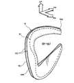
- a passenger seat airbag 10 is configured using an inner panel 12 and an outer panel 14, and a left bag portion 16 located on the left side in the vehicle width direction and a right side in the vehicle width direction.
- a right hand bag portion 18 is provided.
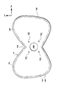
- the inner panel 12 is a single base fabric that faces the vehicle width direction and is sewn together, and is formed in a bilobal left-right symmetric shape in the unfolded state before sewing.
- the vertical dimension A of the portion 12A is smaller than the vertical dimension B of the left and right ends.
- the vertical dimension B of the left and right ends is the maximum vertical dimension of each of the left base fabric 12L located on the left side in the vehicle width direction and the right base fabric 12R located on the right side in the vehicle width direction.
- the vertical dimension B of the left base fabric 12L and the vertical dimension B of the right base fabric 12R are not necessarily the same.
- a laterally long lateral hole 12C is formed at the center in the vehicle width direction of the inner panel 12 in the unfolded state before sewing.
- the shape of the lateral hole 12C is enlarged in the vertical dimension in the left base fabric 12L and the right base fabric 12R so as to be along a sewing line S1 described later. This reduces the amount of base fabric used to form the inner panel 12 compared with the case where the lateral hole 12C is a substantially rectangular shape that is bilaterally symmetric, so that the base fabric used in the passenger seat airbag 10 in the completed state can be reduced. The amount can be reduced.
- the base cloth can be effectively used to reduce the cost. Further, the normal folding size can be further reduced.
- the size of the horizontal hole 12C may be enlarged up and down to bring the edge of the horizontal hole 12C closer to the sewing line S1.
- the lateral hole 12C may be substantially rectangular or other shape. On the contrary, it is good also as a structure which does not provide the horizontal hole 12C.
- the inner panel 12 is folded in two on the occupant side with the center in the vehicle width direction as the center, and the left base fabric 12L located on the left side in the vehicle width direction and the right base located on the right side in the vehicle width direction.
- the cloth 12R is sewn along the sewing line S1 with the cloth 12R facing the vehicle width direction.
- the sewing line S1 is set in a region between the lateral hole 12C and the outer peripheral edge 12D.
- various types of airbags corresponding to the vehicle can be manufactured while the inner panel 12 and the outer panel 14 are shared.
- the lateral hole 12C of the inner panel 12 becomes a notch 12K by folding the inner panel 12 in half.
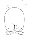
- the outer panel 14 is a single base fabric having an outer shape corresponding to the inner panel 12 and having a gas supply port 14B for expansion formed in the central portion 14A.
- the outer panel 14 is similar to the outer shape of the inner panel 12, and has a left base fabric 14L located on the left side in the vehicle width direction and a right base fabric 14R located on the right side in the vehicle width direction. It is formed into a shape.
- the gas supply port 14B has a circular shape corresponding to a disk-type inflator (not shown), but when a cylinder-type inflator (not shown) is used, for example, a rectangular shape is used. Formed.
- Four holes 14C formed around the gas supply port 14B are for passing bolts when the inflator and the passenger seat airbag 10 are fixed to an airbag case or the like (not shown).
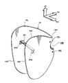
- the inner surface of the left base fabric 14L and the inner surface of the right base fabric 14R in the outer panel 14 may be coupled by a regulating member 20 that regulates the amount of expansion and deployment in the vehicle width direction.
- the restricting member 20 is, for example, a non-extensible tether, and is sewn to the inner surface of the left base fabric 14L and the inner surface of the right base fabric 14R at both ends 20A.
- the regulating member 20 in the present embodiment is provided at a position that crosses the notch 12K (FIG. 3) in the vehicle width direction when the passenger airbag 10 is inflated and deployed. This is to avoid interference between the regulating member 20 and the inner panel 12.
- the outer panel 14 is sewn along the outer peripheral edge 12D of the folded inner panel 12 (sewing part S2). Specifically, the outer panel 14 is folded in two on the occupant side (vehicle rear side) with the center portion 14A as the center, and the left base fabric in the outer panel 14 is formed on the outer peripheral edge portion 12D of the left base fabric 12L in the inner panel 12. 14 ⁇ / b> L of 14 ⁇ / b> L is overlaid, and 14 ⁇ / b> D of the right side base cloth 14 ⁇ / b> R in the outer panel 14 is overlaid on the outer peripheral edge 12 ⁇ / b> D of the right side base cloth 12 ⁇ / b> R in the inner panel 12. And the outer peripheral edge part 12D of the inner side panel 12 and the outer peripheral edge part 14D of the outer side panel 14 are sewn in the sewing part S2.
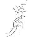
- the position of the sewing line S1 is set inside the sewing portion S2. Accordingly, as shown in FIGS. 1 and 6, when the passenger airbag 10 is inflated and deployed, a recess 22 is formed between the left bag portion 16 and the right bag portion 18 on the passenger side (the vehicle rear side). It is supposed to be formed. The depth of the recess 22 is set to be greater in the vehicle lower portion 22L than in the vehicle upper portion 22U.
- the depth of the recess 22 is a distance from the outer peripheral edge portions 12D and 14D to the sewing line S1 in the vehicle front-rear direction. Therefore, in the present embodiment, the depth DL (FIG. 7) of the concave portion 22 in the vehicle lower portion 22L is set larger than the depth DU (FIG. 8) of the concave portion 22 in the vehicle upper portion 22U.
- the depth DU is set to, for example, 20 to 40 mm
- the depth DL is also set to be larger than the depth DU, for example, 40 to 60 mm.
- the height position of the vehicle upper portion 22U corresponds to the height position of the head 26H of the seated occupant 26, for example, the head of an AM50 (adult male 50th percentile) dummy. Is set.
- the lower portion 22L of the vehicle is set corresponding to the height position of the head 28H of the seated occupant 28, for example, the head of an AF05 (adult female 5th percentile) dummy.
- the passenger seat airbag 10 is housed in an instrument panel 24 of the vehicle together with an inflator (not shown).
- the inflator is electrically connected to an airbag ECU (not shown).
- the inner panel 12 and the outer panel 14 are each assumed to be one base cloth, the present invention is not limited to this, and for example, a pair of left and right base cloths may be used.
- a reinforcing cloth or the like may be appropriately added as a base fabric constituting the passenger seat airbag 10.
- a passenger seat airbag 10 is configured as described above, and the operation thereof will be described below.
- a passenger seat airbag 10 is configured by using an inner panel 12 (FIG. 2) and an outer panel 14 (FIG. 4), each of which is a single base fabric, and these are sewn.
- the number of panels can be reduced and the structure can be simplified.
- the sewing work is easy. For this reason, the manufacturing cost can be significantly reduced.
- the inner panel 12 is formed with a horizontal hole 12C, and the sewing line S1 is set in a region between the horizontal hole 12C and the outer peripheral edge 12D.
- the use amount of the base fabric constituting the panel 12 can be reduced, the manufacturing cost can be further reduced, and the folding size at the normal time can be reduced to improve the mounting property to the vehicle.
- a recess 22 is formed on the passenger side between the left bag portion 16 and the right bag portion 18.
- the shape of the recess 22 can be arbitrarily set by the sewing line S1 between the inner panels 12 when the passenger seat airbag 10 is manufactured. For this reason, it is possible to manufacture various types of airbags according to the vehicle simply by changing the sewing line while sharing the panel.
- the airbag ECU determines that a side collision has occurred based on a signal from the collision sensor, an ignition current is passed from the airbag ECU to the inflator. This activates the inflator to generate a large amount of gas. As shown in FIG. 1, the passenger seat airbag 10 expands from the inside of the instrument panel 24 toward the occupants 26 and 28 (FIG. 9) upon deployment of the gas.
- heads 26H and 28H of occupants 26 and 28 are formed in a recess 22 on the occupant 26 side between the left bag portion 16 and the right bag portion 18 in the inflated passenger seat airbag 10 (see FIG. 1). 9) enters and is restrained. Further, the left shoulders (not shown) of the occupants 26 and 28 are restrained by the left bag part 16, and the right shoulders (not shown) are restrained by the right bag part 18. Thus, the passengers 26 and 28 are stably restrained by the passenger seat airbag 10.
- the depth of the concave portion 22 at the time of inflating and deploying is different in the vehicle vertical direction position, and the vehicle lower portion 22L is set larger than the vehicle upper portion 22U. Accordingly, the occupant 26 having a large physique indicated by a solid line in FIG. 9 is restrained by a relatively shallow portion (the vehicle upper portion 22U) of the recess 22. On the other hand, the occupant 28 having a small physique indicated by a two-dot chain line in FIG. 9 is restrained by a relatively deep portion (the vehicle lower portion 22L) of the recess 22.
- the occupant 26 indicated by a solid line is, for example, an AM50 (adult male 50th percentile) dummy
- the occupant 28 indicated by a two-dot chain line is, for example, an AF05 (adult female 5th percentile) dummy.
- the amount of expansion of the vehicle width expansion at the time of expansion is Since it is regulated by the regulating member 20, it is possible to appropriately inflate and deploy the passenger seat airbag 10 toward the occupant side while saving the gas supply amount.
Landscapes
- Engineering & Computer Science (AREA)
- Mechanical Engineering (AREA)
- Air Bags (AREA)
Abstract
Description
本実施形態は、上記のように構成されており、以下その作用について説明する。図1において、本実施形態に係る助手席用エアバッグ10は、夫々1枚の基布である内側パネル12(図2)と外側パネル14(図4)とを用いて構成され、これらを縫製することで構成されるので、パネルの枚数を抑制でき、構造を単純化できる。また各縫製を平面的に行うことができるので、縫製作業が容易である。このため、製造コストを大幅に低減することが可能である。
10 助手席用エアバッグ
12 内側パネル
12A 中央部
12C 横孔
12D 外周縁部
14 外側パネル
14A 中央部
14B ガス供給口
16 左側バッグ部
18 右側バッグ部
20 規制部材
22 凹部
22L 車両下方部位
22U 車両上方部位
26 乗員
28 乗員
S1 縫製ライン
Claims (5)
- 車幅方向に対向し互いに縫製される内側パネルと、該内側パネルを車幅方向の両側から挟むように設けられる外側パネルとを用いて構成され、
車幅方向左側に位置する左側バッグ部及び車幅方向右側に位置する右側バッグ部が設けられ、
前記左側バッグ部と前記右側バッグ部との間の乗員側の凹部の形状が、前記内側パネル同士の縫製ラインによって設定される助手席用エアバッグ。 - 前記内側パネルは、1枚の基布であり、車幅方向の中央部を中心として前記乗員側に二つ折りされ、車幅方向左側に位置する左側基布と車幅方向右側に位置する右側基布とが、車幅方向に対向した状態で前記縫製ラインに沿って縫製され、
前記外側パネルは、前記内側パネルに対応した外形を有し、中央部に膨張用のガス供給口が形成された1枚の基布であり、二つ折りされた前記内側パネルの外周縁部に沿って縫製されている請求項1に記載の助手席用エアバッグ。 - 前記内側パネルは、縫製前の展開状態において、前記車幅方向の中央部に、左右方向に長い横孔が形成されており、
前記縫製ラインは、該横孔と前記外周縁部との間の領域に設定されている請求項2に記載の助手席用エアバッグ。 - 前記外側パネルにおける車幅方向左側の内面と車幅方向右側の内面とは、車幅方向の膨張展開量を規制する規制部材で連結されている請求項3に記載の助手席用エアバッグ。
- 膨張展開時における前記乗員側の前記凹部の深さは、車両上方部位よりも車両下方部位の方が大きく設定されている請求項1~請求項4の何れか1項に記載の助手席用エアバッグ。
Priority Applications (4)
| Application Number | Priority Date | Filing Date | Title |
|---|---|---|---|
| US13/576,601 US20120299278A1 (en) | 2010-06-04 | 2010-06-04 | Airbag for front passenger's seat |
| PCT/JP2010/059565 WO2011151928A1 (ja) | 2010-06-04 | 2010-06-04 | 助手席用エアバッグ |
| CN201080062851.9A CN102753398B (zh) | 2010-06-04 | 2010-06-04 | 副驾驶席用安全气囊 |
| JP2012518202A JP5327385B2 (ja) | 2010-06-04 | 2010-06-04 | 助手席用エアバッグ |
Applications Claiming Priority (1)
| Application Number | Priority Date | Filing Date | Title |
|---|---|---|---|
| PCT/JP2010/059565 WO2011151928A1 (ja) | 2010-06-04 | 2010-06-04 | 助手席用エアバッグ |
Publications (1)
| Publication Number | Publication Date |
|---|---|
| WO2011151928A1 true WO2011151928A1 (ja) | 2011-12-08 |
Family
ID=45066323
Family Applications (1)
| Application Number | Title | Priority Date | Filing Date |
|---|---|---|---|
| PCT/JP2010/059565 Ceased WO2011151928A1 (ja) | 2010-06-04 | 2010-06-04 | 助手席用エアバッグ |
Country Status (4)
| Country | Link |
|---|---|
| US (1) | US20120299278A1 (ja) |
| JP (1) | JP5327385B2 (ja) |
| CN (1) | CN102753398B (ja) |
| WO (1) | WO2011151928A1 (ja) |
Cited By (2)
| Publication number | Priority date | Publication date | Assignee | Title |
|---|---|---|---|---|
| JP2018500238A (ja) * | 2014-12-24 | 2018-01-11 | ティ.ケイ.ホールディングス、インコーポレイテッド | エアバッグモジュール |
| JP2018024341A (ja) * | 2016-08-10 | 2018-02-15 | トヨタ自動車株式会社 | 助手席エアバッグ装置 |
Families Citing this family (9)
| Publication number | Priority date | Publication date | Assignee | Title |
|---|---|---|---|---|
| JP5930633B2 (ja) * | 2011-09-01 | 2016-06-08 | タカタ株式会社 | エアバッグ、エアバッグ装置及び車両 |
| DE102013012017B4 (de) * | 2013-07-19 | 2019-04-18 | Autoliv Development Ab | Airbag |
| DE102014001506B4 (de) * | 2014-02-06 | 2019-05-29 | Trw Automotive Gmbh | Frontgassack |
| EP3181412B1 (en) * | 2014-02-20 | 2018-08-08 | Dalphi Metal España, S.A. | Airbag |
| US9150186B1 (en) * | 2014-03-13 | 2015-10-06 | Ford Global Technologies, Llc | Passenger airbag with secondary chamber |
| CN107249938B (zh) * | 2015-02-16 | 2020-10-30 | 奥托立夫开发公司 | 气囊装置 |
| CN104760561A (zh) * | 2015-03-24 | 2015-07-08 | 上海东方久乐汽车安全气囊有限公司 | 一种前排乘员气囊 |
| US11724662B2 (en) * | 2019-02-27 | 2023-08-15 | Autoliv Development Ab | Airbag device |
| CN114228659B (zh) * | 2021-12-29 | 2023-02-28 | 宁波均胜汽车安全系统有限公司 | 一种正面气囊 |
Citations (4)
| Publication number | Priority date | Publication date | Assignee | Title |
|---|---|---|---|---|
| JP2001233157A (ja) * | 2000-02-25 | 2001-08-28 | Takata Corp | エアバッグ装置 |
| JP2008001198A (ja) * | 2006-06-21 | 2008-01-10 | Toyoda Gosei Co Ltd | 助手席用エアバッグ |
| JP2008044594A (ja) * | 2006-07-19 | 2008-02-28 | Toyoda Gosei Co Ltd | エアバッグ装置 |
| WO2008035589A1 (fr) * | 2006-09-22 | 2008-03-27 | Autoliv Development Ab | Procédé de fabrication d'un airbag et airbag |
Family Cites Families (14)
| Publication number | Priority date | Publication date | Assignee | Title |
|---|---|---|---|---|
| JP4321228B2 (ja) * | 2003-11-14 | 2009-08-26 | タカタ株式会社 | エアバッグ及びエアバッグ装置 |
| US7152880B1 (en) * | 2005-10-17 | 2006-12-26 | Key Safety Systems, Inc. | Grooved air bag |
| JP4923562B2 (ja) * | 2005-11-10 | 2012-04-25 | タカタ株式会社 | エアバッグ及びエアバッグ装置 |
| JP4923879B2 (ja) * | 2006-09-06 | 2012-04-25 | 豊田合成株式会社 | エアバッグ装置 |
| JP2008284930A (ja) * | 2007-05-15 | 2008-11-27 | Toyoda Gosei Co Ltd | エアバッグ装置 |
| JP2009061867A (ja) * | 2007-09-05 | 2009-03-26 | Toyoda Gosei Co Ltd | 助手席用エアバッグ |
| JP5402218B2 (ja) * | 2008-12-19 | 2014-01-29 | タカタ株式会社 | エアバッグ、エアバッグ装置及び車両 |
| JP5458650B2 (ja) * | 2008-12-19 | 2014-04-02 | タカタ株式会社 | エアバッグ、エアバッグ装置及び車両 |
| JP5440088B2 (ja) * | 2008-12-19 | 2014-03-12 | タカタ株式会社 | エアバッグ装置及び車両 |
| JP2010234882A (ja) * | 2009-03-30 | 2010-10-21 | Fuji Heavy Ind Ltd | エアバッグ |
| US8662527B2 (en) * | 2009-04-24 | 2014-03-04 | Honda Motor Co., Ltd. | Airbag device |
| JP5362501B2 (ja) * | 2009-09-18 | 2013-12-11 | タカタ株式会社 | エアバッグ及びエアバッグ装置 |
| US8657334B2 (en) * | 2011-02-11 | 2014-02-25 | Key Safety Systems, Inc. | Airbag cushion |
| US8944462B2 (en) * | 2011-04-15 | 2015-02-03 | Trw Vehicle Safety Systems Inc. | Air bag with uninflated pocket |
-
2010
- 2010-06-04 JP JP2012518202A patent/JP5327385B2/ja not_active Expired - Fee Related
- 2010-06-04 CN CN201080062851.9A patent/CN102753398B/zh not_active Expired - Fee Related
- 2010-06-04 WO PCT/JP2010/059565 patent/WO2011151928A1/ja not_active Ceased
- 2010-06-04 US US13/576,601 patent/US20120299278A1/en not_active Abandoned
Patent Citations (4)
| Publication number | Priority date | Publication date | Assignee | Title |
|---|---|---|---|---|
| JP2001233157A (ja) * | 2000-02-25 | 2001-08-28 | Takata Corp | エアバッグ装置 |
| JP2008001198A (ja) * | 2006-06-21 | 2008-01-10 | Toyoda Gosei Co Ltd | 助手席用エアバッグ |
| JP2008044594A (ja) * | 2006-07-19 | 2008-02-28 | Toyoda Gosei Co Ltd | エアバッグ装置 |
| WO2008035589A1 (fr) * | 2006-09-22 | 2008-03-27 | Autoliv Development Ab | Procédé de fabrication d'un airbag et airbag |
Cited By (2)
| Publication number | Priority date | Publication date | Assignee | Title |
|---|---|---|---|---|
| JP2018500238A (ja) * | 2014-12-24 | 2018-01-11 | ティ.ケイ.ホールディングス、インコーポレイテッド | エアバッグモジュール |
| JP2018024341A (ja) * | 2016-08-10 | 2018-02-15 | トヨタ自動車株式会社 | 助手席エアバッグ装置 |
Also Published As
| Publication number | Publication date |
|---|---|
| US20120299278A1 (en) | 2012-11-29 |
| JPWO2011151928A1 (ja) | 2013-07-25 |
| JP5327385B2 (ja) | 2013-10-30 |
| CN102753398B (zh) | 2014-12-17 |
| CN102753398A (zh) | 2012-10-24 |
Similar Documents
| Publication | Publication Date | Title |
|---|---|---|
| JP5327385B2 (ja) | 助手席用エアバッグ | |
| JP6411965B2 (ja) | 乗員保護装置 | |
| CN103562018B (zh) | 气囊和气囊装置 | |
| US20110260436A1 (en) | Passenger airbag apparatus | |
| JP2009006860A (ja) | 車両の乗員保護装置 | |
| CN103025587B (zh) | 侧面安全气囊及其制作方法 | |
| US10525924B2 (en) | Occupant leg restraint device | |
| CN113825678A (zh) | 侧安全气囊装置及侧安全气囊装置的制造方法 | |
| CN103796881B (zh) | 副驾驶席用气囊、副驾驶席用气囊装置及车辆 | |
| WO2013077230A1 (ja) | エアバッグ装置 | |
| JP2018086886A (ja) | エアバッグ | |
| JP2018008661A (ja) | 後席用エアバッグ | |
| JP2017149351A (ja) | 車両構造 | |
| JP6517662B2 (ja) | 乗員保護装置 | |
| JP2007083835A (ja) | サイドエアバッグ装置 | |
| JP2005096653A (ja) | 後席用エアバッグ及び後席用エアバッグ装置 | |
| JP5337583B2 (ja) | エアバッグ装置 | |
| JP2011057155A (ja) | 助手席用エアバッグ | |
| JP2007055501A (ja) | 助手席用エアバッグ装置 | |
| JP7797922B2 (ja) | サイドエアバッグ及びサイドエアバッグ装置 | |
| JP5888103B2 (ja) | 車両用エアバッグ装置 | |
| JP5852847B2 (ja) | エアバッグ装置 | |
| JP2017030374A (ja) | 乗員保護装置 | |
| KR102780780B1 (ko) | 차량의 에어백 쿠션 | |
| CN109955822A (zh) | 车辆用侧气囊装置 |
Legal Events
| Date | Code | Title | Description |
|---|---|---|---|
| WWE | Wipo information: entry into national phase |
Ref document number: 201080062851.9 Country of ref document: CN |
|
| 121 | Ep: the epo has been informed by wipo that ep was designated in this application |
Ref document number: 10852532 Country of ref document: EP Kind code of ref document: A1 |
|
| WWE | Wipo information: entry into national phase |
Ref document number: 2012518202 Country of ref document: JP |
|
| WWE | Wipo information: entry into national phase |
Ref document number: 13576601 Country of ref document: US |
|
| NENP | Non-entry into the national phase |
Ref country code: DE |
|
| 122 | Ep: pct application non-entry in european phase |
Ref document number: 10852532 Country of ref document: EP Kind code of ref document: A1 |