WO2011151896A1 - スターリングエンジンの気体潤滑構造 - Google Patents
スターリングエンジンの気体潤滑構造 Download PDFInfo
- Publication number
- WO2011151896A1 WO2011151896A1 PCT/JP2010/059282 JP2010059282W WO2011151896A1 WO 2011151896 A1 WO2011151896 A1 WO 2011151896A1 JP 2010059282 W JP2010059282 W JP 2010059282W WO 2011151896 A1 WO2011151896 A1 WO 2011151896A1
- Authority
- WO
- WIPO (PCT)
- Prior art keywords
- temperature side
- high temperature
- side cylinder
- stirling engine
- piston
- Prior art date
- Legal status (The legal status is an assumption and is not a legal conclusion. Google has not performed a legal analysis and makes no representation as to the accuracy of the status listed.)
- Ceased
Links
Images



Classifications
-
- F—MECHANICAL ENGINEERING; LIGHTING; HEATING; WEAPONS; BLASTING
- F02—COMBUSTION ENGINES; HOT-GAS OR COMBUSTION-PRODUCT ENGINE PLANTS
- F02G—HOT GAS OR COMBUSTION-PRODUCT POSITIVE-DISPLACEMENT ENGINE PLANTS; USE OF WASTE HEAT OF COMBUSTION ENGINES; NOT OTHERWISE PROVIDED FOR
- F02G1/00—Hot gas positive-displacement engine plants
- F02G1/04—Hot gas positive-displacement engine plants of closed-cycle type
- F02G1/043—Hot gas positive-displacement engine plants of closed-cycle type the engine being operated by expansion and contraction of a mass of working gas which is heated and cooled in one of a plurality of constantly communicating expansible chambers, e.g. Stirling cycle type engines
-
- F—MECHANICAL ENGINEERING; LIGHTING; HEATING; WEAPONS; BLASTING
- F02—COMBUSTION ENGINES; HOT-GAS OR COMBUSTION-PRODUCT ENGINE PLANTS
- F02G—HOT GAS OR COMBUSTION-PRODUCT POSITIVE-DISPLACEMENT ENGINE PLANTS; USE OF WASTE HEAT OF COMBUSTION ENGINES; NOT OTHERWISE PROVIDED FOR
- F02G1/00—Hot gas positive-displacement engine plants
- F02G1/04—Hot gas positive-displacement engine plants of closed-cycle type
- F02G1/043—Hot gas positive-displacement engine plants of closed-cycle type the engine being operated by expansion and contraction of a mass of working gas which is heated and cooled in one of a plurality of constantly communicating expansible chambers, e.g. Stirling cycle type engines
- F02G1/053—Component parts or details
-
- F—MECHANICAL ENGINEERING; LIGHTING; HEATING; WEAPONS; BLASTING
- F02—COMBUSTION ENGINES; HOT-GAS OR COMBUSTION-PRODUCT ENGINE PLANTS
- F02G—HOT GAS OR COMBUSTION-PRODUCT POSITIVE-DISPLACEMENT ENGINE PLANTS; USE OF WASTE HEAT OF COMBUSTION ENGINES; NOT OTHERWISE PROVIDED FOR
- F02G2243/00—Stirling type engines having closed regenerative thermodynamic cycles with flow controlled by volume changes
- F02G2243/30—Stirling type engines having closed regenerative thermodynamic cycles with flow controlled by volume changes having their pistons and displacers each in separate cylinders
- F02G2243/32—Regenerative displacers having parallel cylinder, e.g. "Lauberau" or "Schwartzkopff" engines
-
- F—MECHANICAL ENGINEERING; LIGHTING; HEATING; WEAPONS; BLASTING
- F02—COMBUSTION ENGINES; HOT-GAS OR COMBUSTION-PRODUCT ENGINE PLANTS
- F02G—HOT GAS OR COMBUSTION-PRODUCT POSITIVE-DISPLACEMENT ENGINE PLANTS; USE OF WASTE HEAT OF COMBUSTION ENGINES; NOT OTHERWISE PROVIDED FOR
- F02G2253/00—Seals
- F02G2253/60—Sealing of the lubrication circuit
Definitions
- the present invention relates to a gas lubrication structure of a Stirling engine.
- Stirling engines have attracted attention in order to recover exhaust heat and factory exhaust heat of internal combustion engines mounted on vehicles such as passenger cars, buses, and trucks.
- Stirling engines can be expected to have high thermal efficiency, and because they are external combustion engines that heat the working fluid from the outside, they can utilize various low-temperature differential energy alternatives such as solar, geothermal, and exhaust heat regardless of the heat source, saving energy. There is an advantage that helps.
- technologies that are considered to be related to the present invention in configuration are disclosed in, for example, Patent Documents 1 to 6.
- JP 2009-47022 A Japanese Patent Laid-Open No. 61-207862 JP 2005-76557 A JP 2008-128190 A JP 2007-270662 A JP 2005-351243 A
- Patent Document 1 so-called self-supporting static pressure gas lubrication is performed in which a piston is subjected to static pressure gas lubrication with a working fluid introduced from a working space.
- the technique disclosed in Patent Document 1 is advantageous in terms of cost because it does not require a separate pressurizing pump for supplying pressurized working fluid to the inside of the piston when performing static pressure gas lubrication. can do.
- the working fluid when the working fluid is introduced from the working space into the piston, the working fluid received by the heater flows into the working space on the high temperature side cylinder side, so the temperature of the working fluid is very high. .
- the present invention has been made in view of the above problems, and an object thereof is to provide a gas lubrication structure of a Stirling engine capable of realizing a suitable self-supporting static pressure gas lubrication.
- the present invention provides a high temperature side cylinder having a high temperature side cylinder and a high temperature side piston that reciprocates within the high temperature side cylinder as a pair of cylinders, and a reciprocating motion within the low temperature side cylinder and the low temperature side cylinder.
- a low temperature side cylinder including a low temperature side piston, and of the high temperature side piston and the low temperature side piston, at least the high temperature side piston includes a hollow portion, and the high temperature side cylinder and the low temperature side cylinder from the hollow portion.
- a gas lubrication structure for a Stirling engine comprising a working fluid flow structure for introducing a working fluid existing in a low temperature working space where the temperature of the piston is low into at least the high temperature side piston of the high temperature side piston and the low temperature side piston It is.
- the present invention also provides a high temperature side cylinder having a high temperature side cylinder and a high temperature side piston reciprocating in the high temperature side cylinder as a pair of cylinders, and a low temperature side cylinder having a low temperature side piston reciprocating in the low temperature side cylinder.
- a gas lubrication structure of a Stirling engine having an air supply portion for ejecting a working fluid in a clearance formed therebetween, a working space in which the working fluid flows when reciprocating between the high temperature side cylinder and the low temperature side cylinder Among them, the temperature of the working fluid is lower than the working space in the high temperature side cylinder during engine operation.
- the distribution structure is the most among the low-temperature working spaces for the plurality of the pair of cylinders. It is preferable that the low-temperature working space having a low temperature communicates with each of the hollow portions of the high-temperature side piston in each of the plurality of pairs of cylinders.
- the present invention is an approximation in which the Stirling engine linearly reciprocates a corresponding piston among the high temperature side piston and the low temperature side piston for each of the high temperature side cylinder and the low temperature side cylinder included in the pair of cylinders.
- a piston that further includes a linear link mechanism and includes the hollow portion to be connected among the high temperature side piston and the low temperature side piston as the corresponding approximate linear link mechanism when connecting the flow structure to the hollow portion.
- the distribution structure is provided along the approximate linear link mechanism corresponding to the portion, and the portion of the distribution structure provided along the corresponding approximate linear link mechanism is set according to the operation of the corresponding approximate linear link mechanism.
- a movable part comprising a rotatable indirect part and a pipe part connected to each other via the indirect part And, it is preferable the rotation center of the indirect section is a structure in which as to coincide with the fulcrum of the corresponding approximation line linkage.
- the present invention provides a high-temperature side cylinder and a low-temperature side cylinder in a pair of cylinders in which an internal space of a crankcase provided in the Stirling engine and the low-temperature operating space communicating with the flow structure are formed as the pair of cylinders. It is preferable that the structure further includes communication means for communicating with a working space in which a working fluid reciprocatingly flows.
- a suitable self-supporting static pressure gas lubrication can be realized.
- FIG. It is a schematic block diagram of a Stirling engine provided with the gas lubrication structure of the Stirling engine concerning Example 1.
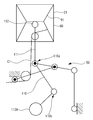
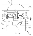
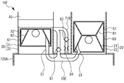
- FIG. It is a schematic block diagram of a piston crank part. It is a figure which shows the movable part of the introductory pipe with which the gas lubrication structure of the Stirling engine concerning Example 1 is provided by making the high temperature side cylinder side into an example.
- FIG. It is a schematic block diagram of the Stirling engine provided with the gas lubrication structure of the Stirling engine concerning Example 3.
- FIG. It is a schematic block diagram of the Stirling engine provided with the gas lubrication structure of the Stirling engine concerning Example 4.
- FIG. 9 is a schematic configuration diagram of a Stirling engine including a gas lubrication structure for a Stirling engine according to a fifth embodiment. It is a schematic block diagram of the principal part of a Stirling engine provided with the gas lubrication structure of the Stirling engine concerning Example 6.
- FIG. 9 is a schematic configuration diagram of a Stirling engine including a gas lubrication structure for a Stirling engine according to a fifth embodiment. It is a schematic block diagram of the principal part of a Stirling engine provided with the gas lubrication structure of the Stirling engine concerning Example 6.
- FIG. 1 is a schematic configuration diagram of a Stirling engine 10A having a gas lubrication structure of a Stirling engine according to the present embodiment.
- the Stirling engine 10A is a two-cylinder ⁇ -type Stirling engine having a high-temperature side cylinder 20 and a low-temperature side cylinder 30 as a pair of cylinders.
- the cylinders 20 and 30 have a crank axis CL extending direction and a cylinder arrangement direction. They are arranged in series and parallel so that X is parallel to each other.
- the high temperature side cylinder 20 includes an expansion piston 21 and a high temperature side cylinder 22 that are high temperature side pistons
- the low temperature side cylinder 30 includes a compression piston 31 and a low temperature side cylinder 32 that are low temperature side pistons.
- the compression piston 31 that reciprocates in the low temperature side cylinder 32 is provided with a phase difference so as to move with a delay of about 90 ° in crank angle with respect to the expansion piston that reciprocates in the high temperature side cylinder
- the upper space of the high temperature side cylinder 22 is an expansion space.
- the working fluid heated by the heater 47 flows into the expansion space.
- the heater 47 is specifically disposed inside an exhaust pipe 100 of a gasoline engine mounted on a vehicle.
- the Stirling engine 10A is arranged such that the extending direction of the crank axis CL (in other words, the cylinder arrangement direction X) is parallel to the exhaust gas flow direction V1.
- the working fluid is heated by heat energy recovered from the exhaust gas that is a fluid constituting the high-temperature heat source.
- the upper space of the low temperature side cylinder 32 is a compression space. The working fluid cooled by the cooler 45 flows into the compression space.
- the regenerator 46 exchanges heat with a working fluid that reciprocates between an expansion space and a compression space, which are working spaces. Specifically, the regenerator 46 receives heat from the working fluid when the working fluid flows from the expansion space to the compression space, and releases the stored heat to the working fluid when the working fluid flows from the compression space to the expansion space. . Air is applied to the working fluid.
- a gas such as He, H 2 , or N 2 can be applied to the working fluid.
- the heat source of the Stirling engine 10A is exhaust gas of the internal combustion engine of the vehicle, the amount of heat to be obtained is limited, and it is necessary to operate the Stirling engine 10A within the range of the obtained amount of heat. . Therefore, in this embodiment, the internal friction of the Stirling engine 10A is reduced as much as possible. Specifically, gas lubrication is performed between the cylinders 22 and 32 and the pistons 21 and 31 in order to eliminate the friction loss due to the piston ring having the largest friction loss among the internal friction of the Stirling engine 10A.
- the pistons 21 and 31 are made to float in the air by using the pressure (distribution) of air generated by a minute clearance between the cylinders 22 and 32 and the pistons 21 and 31. Since the gas lubrication for floating an object in the air has a very small sliding resistance, the internal friction of the Stirling engine 10A can be greatly reduced.
- the clearance between the cylinders 22 and 32 where the gas lubrication is performed and the pistons 21 and 31 is several tens of ⁇ m. Then, the working fluid of the Stirling engine 10A is interposed in this clearance.
- Each of the pistons 21 and 31 is supported in a non-contact state or an allowable contact state with the cylinders 22 and 32 by gas lubrication.
- both the pistons 21 and 31 and the cylinders 22 and 32 are made of metal.
- the corresponding pistons 21 and 31 and the cylinders 22 and 32 have the same linear expansion coefficient (here, SUS). Has been applied. Thereby, even if there is thermal expansion, it is possible to perform gas lubrication while maintaining an appropriate clearance.
- the side force of the pistons 21 and 31 must be made substantially zero. That is, when performing gas lubrication, the ability of the cylinders 22 and 32 to withstand the force in the diametrical direction (lateral direction and thrust direction) (pressure resistance ability) is reduced. The motion accuracy needs to be high.
- a grasshopper mechanism 50 is employed in the piston / crank portion.
- a watt mechanism is available as a mechanism for realizing the linear motion, but the size of the mechanism required for obtaining the same linear motion accuracy is smaller than that of the other mechanisms.
- the entire apparatus can be made compact.
- the Stirling engine 10A of this embodiment is installed in a limited space such as under the floor of an automobile, the degree of freedom of installation increases when the entire apparatus is compact.
- the grasshopper mechanism 50 is advantageous in terms of fuel consumption because the weight of the mechanism required to obtain the same linear motion accuracy is lighter than that of the other mechanisms. Further, the grasshopper mechanism 50 has an advantage that the structure (manufacturing and assembly) is easy because the structure of the mechanism is relatively simple.
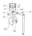
- FIG. 2 is a diagram schematically showing a schematic configuration of a piston / crank portion of the Stirling engine 10A. Since the piston / crank portion employs a common configuration for the high temperature side cylinder 20 side and the low temperature side cylinder 30 side, only the high temperature side cylinder 20 side will be described below, and the low temperature side cylinder 30 side will be described. Description of is omitted.
- the approximate linear link mechanism includes a grasshopper mechanism 50, a connecting rod 110, an extension rod 111, and a piston pin 112.
- the expansion piston 21 is connected to the crankshaft 113A through a connecting rod 110, an extension rod 111, and a piston pin 112. Specifically, the expansion piston 21 is connected to one end side of the extension rod 111 via a piston pin 112.
- a small end portion 110 a of the connecting rod 110 is connected to the other end side of the extension rod 111.
- the large end portion 110b of the connecting rod 110 is connected to the crankshaft 113A.
- the approximate linear link mechanism may have a configuration in which a link member is further provided between the extension rod 111 and the piston pin 112.
- the reciprocating motion of the expansion piston 21 is transmitted to the crankshaft 113A provided in the crankcase 120A by the connecting rod 110, where it is converted into rotational motion.
- the connecting rod 110 is supported by a grasshopper mechanism 50 and reciprocates the expansion piston 21 linearly.
- the side force F of the expansion piston 21 becomes almost zero. For this reason, even when performing gas lubrication with a small load capacity, the expansion piston 21 can be sufficiently supported.
- the layer 60 is provided by coating a resin.
- the resin has a higher linear expansion coefficient than the base material of the metal expansion piston 21 and is a flexible material.
- the resin is specifically a fluorine-based resin. Since the resin generally has a linear expansion coefficient that is about 4 to 10 times higher than that of metal, it is difficult to apply the resin to the outer peripheral surface of the expansion piston 21 having a radial clearance of about several tens of ⁇ m.
- the linear expansion coefficient of the layer 60 is a linear expansion coefficient that can reduce the clearance formed between the high temperature side cylinder 22 and the temperature.
- the thickness of the layer 60 at room temperature is equal to or greater than the radial clearance. In this embodiment, the thickness of the layer 60 is more than twice the size of the radial clearance.
- the thickness of the layer 60 is realized by coating the resin overlying a plurality of times. Further, the thickness of the layer 60 at room temperature is such that the clearance formed between the high temperature side cylinder 22 can be maintained even if thermal expansion occurs under use conditions.
- the temperature of the working fluid varies from the atmospheric temperature to several hundred degrees Celsius, the normal temperature is a minimum of about ⁇ 40 ° C., for example, and the operating temperature is a maximum of about 400 ° C.
- a metal here, SUS
- SUS metal having the same linear expansion coefficient
- the thickness of the layer 60 having a higher linear expansion coefficient than that of the metal increases after the thermal expansion, and thus the radial clearance decreases after the thermal expansion.
- the size of foreign matter that can enter the radial clearance is basically limited to foreign matters smaller than the radial clearance at normal temperature, and the maximum radius is assumed assuming that the layer 60 is in contact with the high temperature side cylinder 22 exceptionally. It is about twice the size of the clearance.
- the expansion piston 21 (more precisely, the layer 60) and the high temperature side cylinder 22
- the foreign matter that has intervened is, for example, in the layer 60 during thermal expansion. Due to the flexibility, it bites into the layer 60 and is collected. Further, during the subsequent operation of the engine, the expansion piston 21 (more precisely, the layer 60) is buried in the flexible layer 60 when it comes close to the high temperature side cylinder 22 or in some cases contacts. As a result, the surface pressure is prevented from increasing due to the intervening foreign matter, so that adhesion can be prevented from occurring.
- the intrusion and growth of the foreign substances can be allowed until the foreign substances have a size obtained by adding the radial clearance and the thickness of the layer 60.
- the layer 60 is formed of a fluorine-based resin that is a material having a solid lubricating function, adhesion due to the layer 60 itself can be prevented.
- the compression piston 31 is also provided with a layer 61 capable of burying foreign matter.
- the thickness of the layer 61 can be set under the use conditions on the low temperature side cylinder 30 side as compared with the layer 60.
- the layer 60 is provided within a predetermined range from the lower end of the expansion piston 21 to before reaching the upper end in order to avoid heat damage from the working fluid existing in the working space of the heater 47 and the high temperature side cylinder 22.
- the layer 61 can generally be provided from the upper end to the lower end of the compression piston 31.
- the Stirling engine 10A performs a hydrostatic gas lubrication in which a pressurized fluid is ejected and an object is floated by the generated static pressure.
- the expansion piston 21 is provided with a pressure accumulation chamber R1
- the compression piston 31 is provided with a pressure accumulation chamber R2.
- the pressure accumulating chambers R1 and R2 are provided along the side walls of the pistons 21 and 31, and have a space formed in a ring shape over the entire circumference.
- Each of the pressure accumulation chambers R1 and R2 corresponds to a hollow portion.
- the expansion piston 21 is provided with an air supply hole S1, and the compression piston 31 is provided with an air supply hole S2.
- the air supply holes S1 and S2 are provided in the side walls of the pistons 21 and 31, and a plurality of air supply holes S1 and S2 are provided at equal intervals in the circumferential direction.
- the air supply hole S1 ejects a working fluid into a clearance formed between the pressure accumulation chamber R1 and the corresponding cylinder (that is, the high temperature side cylinder 22) among the cylinders 22 and 32, and the air supply hole S2 extends from the pressure accumulation chamber R2 to the cylinder 22.
- the working fluid is ejected into a clearance formed between the corresponding cylinder (that is, the low temperature side cylinder 32).
- Each of the air supply holes S1 and S2 corresponds to an air supply unit.
- the temperature of the working fluid is lower than the working space (that is, the expansion space) in the high temperature side cylinder 22 in the working space in which the working fluid flows when reciprocating between the cylinders 20 and 30.
- 70 A of introduction pipes which introduce the working fluid which exists in the low-temperature working space which becomes into the inside of expansion piston 21 at least among expansion piston 21 and compression piston 31 are further provided.
- the introduction pipe 70A is specifically provided to introduce the working fluid existing in the low temperature working space into the pistons 21 and 31, respectively.
- the introduction pipe 70A provided in this way communicates the low temperature working space and the pressure accumulating chamber R1 provided in the expansion piston 21, and communicates the low temperature working space and the pressure accumulating chamber R2 provided in the compression piston 31. .
- the low-temperature working space is preferably a portion of the working space in which the working fluid flows when reciprocating between the cylinders 20 and 30 where the temperature of the working fluid is lowest during engine operation.
- the low temperature working space is specifically a working space (that is, a compression space) formed in the low temperature side cylinder 32.
- the end of the introduction pipe 70A on the low-temperature working space side is connected to the end of the low-temperature side cylinder 32 on the cooler 45 side, so that the introduction pipe 70A is connected to the low-temperature side.
- the low-temperature working space may be a working space formed in the cooler 45 or a working space formed by the low-temperature side cylinder 32 and the working space formed in the cooler 45, for example.
- the introduction pipe 70A In connecting the introduction pipe 70A to the pressure accumulation chambers R1 and R2, the introduction pipe 70A is provided so as to be routed from the side where the approximate linear link mechanism is provided with respect to the pressure accumulation chambers R1 and R2. Then, when connecting the introduction pipe 70A to the pressure accumulating chambers R1 and R2, the introduction pipe 70A is based on the reciprocating motion of a piston (for example, the expansion piston 21 having the pressure accumulation chamber R1) provided with the pressure accumulation chamber to be connected.
- the movable part C1 which can absorb the change of a position is provided.
- the length is set so that no tension is applied or light tension is applied.
- the resin tube is applied to the movable part C1.
- a resin tube can be made of, for example, silicon, and the movable portion C1 made of a resin tube has a piston 21 and 31 having a pressure accumulating chamber to be connected, as the piston moves from the top dead center toward the bottom dead center. , Gradually come loose.
- the movable part C1 is provided so as not to be entangled with the linear approximation link mechanism when slackened.
- a first check valve 81 is provided in the introduction pipe 70 ⁇ / b> A.
- the first check valve 81 is provided so as to permit the flow of the working fluid from the low temperature working space and prohibit the flow of the working fluid to the low temperature working space.
- the first check valve 81 is provided in a portion from the end portion on the low-temperature working space side until the introduction pipe 70A branches toward the pressure accumulation chambers R1 and R2.
- the first check valve 81 provided in this way is provided so as to be able to maintain the pressurized state of the working fluid introduced into the interior of the expansion piston 21 (specifically, the pressure accumulating chamber R1).
- the first check valve 81 is a pressurized fluid holding unit that holds the pressurized state of the working fluid introduced by the introduction pipe 70A.
- the working fluid is unlikely to flow out of the air supply holes S1 and S2 until the pressure in the pressure accumulating chambers R1 and R2 increases to some extent.
- the introduction pipe 70A corresponds to a flow structure of the working fluid, and the Stirling engine 10A realizes a gas lubrication structure of a Stirling engine including the introduction pipe 70A and the first check valve 81 when performing static pressure gas lubrication. Has been.
- this gas lubrication structure when performing static pressure gas lubrication, the introduction pipe 70A introduces the working fluid from the low temperature working space to the inside of the expansion piston 21 (specifically, the pressure accumulating chamber R1). For this reason, this gas lubrication structure can prevent the thermal deformation of the expansion piston 21 from being promoted as compared with the case where the working fluid is introduced from the expansion space into which the working fluid received by the heater 47 flows. And this gas lubrication structure can implement
- the compression space is a low-temperature working space.
- the temperature of the working fluid is low.
- this gas lubrication structure can suitably prevent or suppress the occurrence of heat damage and also suppress the occurrence of heat loss that occurs when the working fluid immediately after receiving heat by the heater 47 is used for static pressure gas lubrication. In view of this, suitable self-supporting hydrostatic gas lubrication can be realized.
- this gas lubrication structure connects the end of the introduction pipe 70A on the low-temperature working space side to the end on the cooler 45 side of the low-temperature side cylinder 32, so that the temperature can be increased when performing static pressure gas lubrication.
- a more suitable self-supporting hydrostatic gas lubrication can be realized in that a working fluid in a low state can be introduced.
- the working fluid is introduced from the low temperature working space to the inside of the expansion piston 21 (specifically, the pressure accumulating chamber R1), so that it is introduced from the inside of the expansion piston 21 until it is ejected.
- the temperature of the working fluid rises, and as a result, the volume of the working fluid at the time of ejection becomes larger than that at the time of introduction. For this reason, this gas lubrication structure can perform static pressure gas lubrication with a smaller amount of working fluid on the high temperature side cylinder 20 side.
- the gas lubrication structure can easily secure the amount of the working fluid, and can suppress the reduction in the output of the Stirling engine 10A by introducing a part of the working fluid from the working space.
- a suitable self-supporting static pressure gas lubrication can be realized.
- the introduction pipe 70A further introduces the working fluid from the low temperature working space into the compression piston 31 (specifically, the pressure accumulating chamber R2).
- this gas lubrication structure can share the first check valve 81 that holds the pressurized fluid between the cylinders 20 and 30 when performing static pressure gas lubrication on the low temperature side cylinder 30 side.
- a suitable self-supporting hydrostatic gas lubrication can also be realized in that the configuration can be simplified.
- the introduction pipe 70A is made of a resin tube that has a sufficient margin for the reciprocating motion of the pistons 21 and 31.
- a movable part C1 is provided. And this gas lubrication structure can implement
- FIG. 4 is a schematic configuration diagram of a Stirling engine 10B having a gas lubrication structure of the Stirling engine according to the present embodiment.
- the Stirling engine 10B is a four-cylinder multi-cylinder Stirling engine having a plurality (two in this case) of a pair of cylinders composed of a high temperature side cylinder 20 and a low temperature side cylinder 30.
- the crankshaft 113B is substantially the same as the Stirling engine 10A except that the crankshaft 113B is provided instead of the crankcase 120A, and the introduction pipe 70B is provided instead of the introduction pipe 70A. Yes.
- crankshaft 113B and the crankcase 120B are substantially the same as the crankshaft 113A and the crankcase 120A except that they are compatible with a 4-cylinder multi-cylinder Stirling engine.
- the crankshaft 113B specifically converts the reciprocating motions of the pistons 21 and 31 of the cylinders 20 and 30 included in the plurality of pairs of cylinders into rotational motions.
- the crankcase 120B is configured such that the cylinders 20 and 30 included in the plurality of pairs of cylinders are provided in series and parallel to each other between the plurality of pairs of cylinders.
- the introduction pipe 70B exists in any one of the low-temperature operating spaces of the plurality of pairs of cylinders, not for each of the plurality of pairs of cylinders, when performing static pressure gas lubrication in the Stirling engine 10B.
- the working fluid is introduced into at least the inside of the expansion piston 21 among the pistons 21 and 31 provided in each of the plurality of pairs of cylinders.
- the introduction pipe 70B is provided so as to introduce the working fluid existing in the above-described low-temperature working space into each of the pistons 21 and 31 provided in each of the plurality of pairs of cylinders.
- the introduction pipe 70B provided in this way communicates the above-described low-temperature working space with each of the pressure accumulating chambers R1 included in the expansion piston 21 in each of the plurality of pairs of cylinders, Each of the plurality of pairs of cylinders communicates with each of the pressure accumulation chambers R2 included in the compression piston 31.
- the low-temperature working space is an expansion space as in the case of Example 1.
- the end of the introduction pipe 70B on the low-temperature working space side is connected to the end of the low-temperature side cylinder 32 on the cooler 45 side.
- the above-described low-temperature operating space is specifically a low-temperature operating space for a pair of cylinders located upstream in the exhaust circulation direction V1 among a plurality of pairs of cylinders.
- the low-temperature working space with which the introduction pipe 70B communicates may be, for example, a low-temperature working space for a pair of cylinders located downstream in the exhaust gas flow direction V1 among a plurality of pairs of cylinders.
- the low temperature operating space in which the introduction pipe 70B communicates can be, for example, the lowest temperature operating space among the low temperature operating spaces for each of the plurality of pairs of cylinders.
- the introduction pipe 70B In connecting the introduction pipe 70B to the pressure accumulating chambers R1 and R2, the introduction pipe 70B also includes the movable portion C1 as in the case of the first embodiment.
- the introduction pipe 70B is also provided with a first check valve 81 in the same manner as in the first embodiment, and the first check valve 81 is provided from the end of the introduction pipe 70B on the low-temperature working space side. , Provided until the introduction pipe 70B branches.
- the first check valve 81 provided in this way can maintain the pressurized state of the working fluid introduced into the interior (specifically, the pressure accumulation chamber R1) of the expansion piston 21 provided in each of the plurality of pairs of cylinders.
- the introduction pipe 70B corresponds to a working fluid flow structure, and the Stirling engine 10B realizes a Stirling engine gas lubrication structure including the introduction pipe 70B and the first check valve 81 when performing static pressure gas lubrication. Has been.
- each of the plurality of pairs of cylinders includes the working fluid that exists in any one of the low-temperature working spaces among the low-temperature working spaces in which the introduction pipes 70B are formed for the plurality of pairs of cylinders. , 31 is introduced into each interior.
- this gas lubrication structure when introducing the working fluid from the low-temperature working space, one introduction pipe 70B can be used, thereby comparing with the case where the introduction pipe 70A is applied to each of a plurality of pairs of cylinders.
- a suitable self-supporting hydrostatic gas lubrication can be realized in that the number of parts can be reduced and the configuration can be simplified. This also allows the gas lubrication structure to share the first check valve 81 that holds the pressurized fluid between all the cylinders 20 and 30, thereby reducing the number of parts and simplifying the configuration. In view of this, suitable self-supporting static pressure gas lubrication can be realized.
- the gas lubrication structure suitably generates heat damage by setting the low-temperature working space in communication with the introduction pipe 70B to the low-temperature working space having the lowest temperature among the low-temperature working spaces for each of the plurality of pairs of cylinders.
- a suitable self-supporting hydrostatic gas lubrication can be realized in that it can be prevented or suppressed and generation of heat loss can be suitably suppressed.
- FIG. 5 is a schematic configuration diagram of a Stirling engine 10C having a gas lubrication structure of the Stirling engine according to the present embodiment.
- the Stirling engine 10C is substantially the same as the Stirling engine 10A except that the Stirling engine 10C includes an introduction pipe 70C instead of the introduction pipe 70A and a low temperature side cylinder 30 'instead of the low temperature side cylinder 30. It has become.
- the low temperature side cylinder 30 ′ is substantially the same as the low temperature side cylinder 30 except that the compression piston 31 ′ is provided instead of the compression piston 31.
- the compression piston 31 ' is substantially the same as the compression piston 31 except that the working fluid is introduced by a method different from that of the compression piston 31 when performing static pressure gas lubrication on the low temperature side cylinder 30' side.
- the same change can be applied to the Stirling engine 10B described in the second embodiment, for example.
- the compression piston 31' is provided with a second check valve 82.
- the second check valve 82 is provided in the upper part of the compression piston 31 ′ and in the compression piston 31 ′ (specifically, the pressure accumulation chamber R 2), and permits the working fluid to flow from the compression space. In addition, the flow of the working fluid to the compression space is prohibited.
- the second check valve 82 provided in this manner operates from the compression space to the inside of the compression piston 31 '(specifically, the pressure accumulation chamber R2) when performing static pressure gas lubrication on the low temperature side cylinder 30' side. It is provided so that the fluid can be introduced directly and the pressurized state of the working fluid introduced into the compression piston 31 ′ can be maintained.
- the introduction pipe 70C is substantially the same as the introduction pipe 70A, except that the introduction of working fluid existing in the low-temperature working space is introduced only into the expansion piston 21 of the pistons 21 and 31 '. Has become.
- the introduction pipe 70 ⁇ / b> C provided in this way specifically communicates the low-temperature working space and the pressure accumulation chamber R ⁇ b> 1 included in the expansion piston 21. Therefore, in the Stirling engine 10C, the first check valve 81 can maintain the pressurized state of the working fluid introduced into the inside of the expansion piston 21 (specifically, the pressure accumulation chamber R1) out of the pistons 21 and 31 ′. Is provided.
- the introduction pipe 70C corresponds to a working fluid flow structure, and the Stirling engine 10C realizes a Stirling engine gas lubrication structure including the introduction pipe 70C and the first check valve 81 when performing static pressure gas lubrication. Has been.
- the effect of the gas lubrication structure of the Stirling engine according to this embodiment will be described.
- the working fluid in which the introduction pipe 70C exists in the low-temperature working space is introduced only into the expansion piston 21 (specifically, the pressure accumulation chamber R1) of the pistons 21 and 31 ′. Yes.
- the first check valve 81 cannot be shared between the cylinders 20 and 30 '
- the gas lubrication structure described in the first embodiment in the other points is provided by providing the introduction pipe 70C. The same operational effects can be achieved.
- this gas lubrication structure by providing the introduction pipe 70C, the movable part C1 corresponding to the compression piston 31 among the movable parts C1 provided in the introduction pipe 70A described in the first embodiment can be eliminated.
- this gas lubrication structure can realize suitable self-supporting static pressure gas lubrication also in that the reliability can be improved by reducing the number of movable parts C1 which are concerned about the reliability.
- FIG. 6 is a schematic configuration diagram of a Stirling engine 10D having a gas lubrication structure of the Stirling engine according to the present embodiment.
- the Stirling engine 10D is substantially the same as the Stirling engine 10A except that an introduction pipe 70D is provided instead of the introduction pipe 70A.
- the introduction pipe 70D is substantially the same as the introduction pipe 70A except that the introduction section 70D includes a movable section C2 instead of the movable section C1.
- the same change can be applied to the Stirling engines 10B and 10C described in the second embodiment, for example.
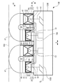
- the introduction pipe 70D In connecting the introduction pipe 70D to the pressure accumulating chambers R1 and R2, in the Stirling engine 10D, as a corresponding approximate linear link mechanism as shown in FIG. 7, the pressure accumulating chamber to be connected among the pistons 21 and 31 (example shown in FIG. 7). Then, the introduction pipe 70D is provided along the approximate linear link mechanism corresponding to the piston (the expansion piston 21 in the example shown in FIG. 7) having the pressure accumulating chamber R1). In the Stirling engine 10D, the indirect portion C21 and the indirect portion C21 that can rotate the portion provided along the corresponding approximate linear link mechanism in the introduction pipe 70D according to the operation of the corresponding approximate linear link mechanism.
- the movable portion C2 is provided with a piping portion C22 connected to each other through the rotation portion C2, and the rotation center of the indirect portion C21 is provided so as to coincide with the fulcrum P of the corresponding approximate linear link mechanism. And the movable part C2 of such a structure performs the operation
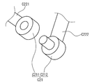
- the indirect portion C21 includes a ring-shaped connection portion C211 at the end of one piping portion C221 of two piping portions C22 that are connected to each other via the indirect portion C21.
- a cylindrical connection part C212 that fits into the ring-shaped connection part C211 is provided at the end of the other piping part C222, and the cylindrical connection part C212 is rotatably fixed to the ring-shaped connection part C211.
- each of the flow paths of the two pipe portions C221 and C222 includes an opening (for example, a ring-shaped opening) provided on the inner peripheral surface of the ring-shaped connection portion C211 in the indirect portion C21, and a columnar shape.
- connection part C211 and the piping part C221 may be comprised with an integral component, and may be a mutually separate component. The same applies to the connection portion C212 and the piping portion C222.
- the introduction pipe 70D corresponds to a flow structure of the working fluid, and the Stirling engine 10D realizes a Stirling engine gas lubrication structure including the introduction pipe 70D and the first check valve 81 when performing static pressure gas lubrication. Has been.
- the introduction pipe 70D when the introduction pipe 70D is connected to the pressure accumulating chambers R1 and R2, the introduction pipe 70D includes a movable portion C2 that performs an operation following the operation of the approximate linear link mechanism. For this reason, this gas lubrication mechanism makes it possible to make the movable part C2 made of a metal having a higher durability compared to the resin, thereby improving the reliability. Gas lubrication can be realized.
- FIG. 9 is a schematic configuration diagram of a Stirling engine 10E having a gas lubrication structure of the Stirling engine according to the present embodiment.
- the Stirling engine 10E is substantially the same as the Stirling engine 10A except that the Stirling engine 10E further includes a communication pipe 71A, a third check valve 83, and a throttle valve 84.
- the same change can be applied to the Stirling engines 10B, 10C, and 10D described in the second, third, and fourth embodiments, for example.
- the working fluid that reciprocates between the high temperature side cylinder 20 and the low temperature side cylinder 30 flows in a pair of cylinders in which the internal space of the crankcase 120A and the low temperature operation space where the introduction pipe 70A communicates are formed. It is provided so as to communicate with the working space and corresponds to communication means.
- the communication pipe 71A is specifically provided so as to connect the internal space of the crankcase 120A and the low-temperature working space with which the introduction pipe 70A communicates.
- the communication pipe 71A is provided so as to communicate the internal space of the crankcase 120A and the compression space, and the end of the communication pipe 71A thus provided on the low-temperature working space side is
- the low temperature side cylinder 32 is connected to the end on the cooler 45 side.
- the third check valve 83 is provided so as to be interposed in the communication pipe 71A, permits the working fluid to flow from the inner space of the crankcase 120A, and allows the working fluid to flow into the inner space of the crankcase 120A. It is provided to prohibit distribution.
- the third check valve 83 provided in this way prohibits the flow of the working fluid into the internal space of the crankcase 120A, while the pressure in the working space with which the communication pipe 71A communicates is increased within the crankcase 120A.
- the replenishment means can replenish the working fluid from the crankcase 120A to the working space to which the communication pipe 71A communicates.
- the throttle valve 84 is provided so as to be interposed in a portion of the communication pipe 71A closer to the crankcase 120A than the third check valve 83, and adjusts the flow rate of the working fluid flowing through the communication pipe 71A. It is a means. In this respect, the throttle degree of the throttle valve 84 is set in advance so that the flow rate of the working fluid to be replenished from the crankcase 120A to the working space communicated with the communication pipe 71A becomes an appropriate amount.
- a gas lubrication structure of a Stirling engine including an introduction pipe 70A, a communication pipe 71A, a first check valve 81, a third check valve 83, and a throttle valve 84 is realized. Has been.
- the communication pipe 71A communicates the internal space of the crankcase 120A and the working space in the pair of cylinders in which the low-temperature working space that communicates with the introduction pipe 70A is formed. For this reason, in this gas lubrication structure, even if the pressure in the working space is reduced due to the static pressure gas lubrication for introducing the working fluid via the introduction pipe 70A, the inside of the crankcase 120A is changed according to the pressure difference. By replenishing the working fluid from the space to the working space via the communication pipe 71A, such a pressure drop can be prevented or suppressed.
- this gas lubrication structure can prevent or suppress a decrease in the output of the Stirling engine 10E due to the static pressure gas lubrication in which the working fluid is introduced through the introduction pipe 70A.
- Pressure gas lubrication can be realized.
- This gas lubrication structure is also suitable in that the working fluid can be replenished with high responsiveness by providing the communication pipe 71A so as to communicate the internal space of the crankcase 120A and the low-temperature working space where the introduction pipe 70A communicates. Self-supporting static pressure gas lubrication can be realized.
- this gas lubrication structure is provided with a third check valve 83 in the communication pipe 71A, so that the working fluid can be replenished while maintaining the pressure of the working space with a simple configuration, and thus a suitable self-supporting static static structure can be obtained. Pressure gas lubrication can be realized.
- this gas lubrication structure is provided with a throttle valve 84 in the communication pipe 71A, so that, for example, a situation in which the working fluid is replenished more than necessary from the internal space of the crankcase 120A to the working space in accordance with a large pressure difference is prevented or suppressed.
- a suitable self-supporting hydrostatic gas lubrication from the viewpoint that an appropriate amount of the working fluid can be added to obtain a desired output of the Stirling engine 10E.
- FIG. 10 is a schematic configuration diagram of a main part of a Stirling engine 10F having a gas lubrication structure of the Stirling engine according to the present embodiment.
- the Stirling engine 10F is substantially the same as the Stirling engine 10E except that an introduction pipe 70E is provided instead of the introduction pipe 70A, and a communication pipe 71B is provided instead of the communication pipe 71A.
- the same change can be applied to, for example, the Stirling engines 10B, 10C, and 10D to which the same change as in the fifth embodiment is applied.
- the introduction pipe 70E and the communication pipe 71B are substantially the same as the introduction pipe 70A and the communication pipe 71A except that a part of the flow path through which the working fluid flows is made common.
- the introduction pipe 70E and the communication pipe 71B specifically have a common end on the low-temperature working space side.
- a Stirling engine gas lubrication structure including an introduction pipe 70E, a communication pipe 71B, a first check valve 81, a third check valve 83, and a throttle valve 84 is realized. Has been.
- the effect of the gas lubrication structure of the Stirling engine according to this embodiment will be described.
- this gas lubrication structure by sharing a part of the flow path through which the working fluid flows between the introduction pipe 70E and the communication pipe 71B, the cost can be reduced by reducing the number of parts and the Stirling engine 10F can be made compact. In terms of being able to achieve, it is possible to realize a self-supporting static pressure gas lubrication that is more suitable than the Stirling engine 10E.
- the end portion on the low-temperature working space side is made common between the introduction pipe 70E and the communication pipe 71B, so that the introduction port 70E and the communication pipe 71B are provided with the connection port for the introduction pipe 70E and the communication pipe 71B.
- the connection port of the pipe 70E and the communication pipe 71B can be shared. For this reason, in this gas lubrication structure, when the connection port for the introduction pipe 70E and the communication pipe 71B is provided in the low temperature side cylinder 32, the manufacture of the low temperature side cylinder 32 is facilitated and the cost is reduced by the common connection port. In view of this, suitable self-supporting static pressure gas lubrication can be realized.
Landscapes
- Engineering & Computer Science (AREA)
- Chemical & Material Sciences (AREA)
- Combustion & Propulsion (AREA)
- Mechanical Engineering (AREA)
- General Engineering & Computer Science (AREA)
- Pistons, Piston Rings, And Cylinders (AREA)
- Lubrication Of Internal Combustion Engines (AREA)
Abstract
Description
スターリングエンジンに関し、構成上、本発明と関連性があると考えられる技術が例えば特許文献1から6までで開示されている。
また高温側気筒側の作動空間からピストンの内部に導入した作動流体の温度は、給気孔から噴出される際には導入時よりも低下することになる。このためこの場合には、噴出時の作動流体の容積が導入時よりも小さくなり、この結果、気体潤滑に必要な作動流体の量を確保することが困難であることが考えられる。
低温側シリンダ32の上部空間は圧縮空間となっている。圧縮空間には冷却器45で冷却された作動流体が流入する。
再生器46は、作動空間である膨張空間および圧縮空間の間を往復する作動流体との間で熱の授受を行う。再生器46は具体的には、作動流体が膨張空間から圧縮空間へと流れる時には作動流体から熱を受け取り、作動流体が圧縮空間から膨張空間へと流れる時には蓄えられた熱を作動流体に放出する。
作動流体には空気が適用されている。但しこれに限られず、作動流体には例えばHe、H2、N2等の気体を適用することができる。
気体潤滑が行われるシリンダ22、32とピストン21、31との間のクリアランスは数十μmとなっている。そして、このクリアランスにはスターリングエンジン10Aの作動流体が介在している。ピストン21、31それぞれは気体潤滑によりシリンダ22、32と非接触の状態、または許容できる接触状態で支持されている。したがってピストン21、31の周囲には、ピストンリングは設けられておらず、また一般にピストンリングと共に使用される潤滑油も使用されていない。気体潤滑では、微小クリアランスにより膨張空間、圧縮空間それぞれの気密が保たれ、リングレスかつオイルレスでクリアランスシールが行われる。
さらにピストン21、31とシリンダ22、32とはともに金属製であり、本実施例では具体的には対応するピストン21、31およびシリンダ22、32同士で線膨張率が同じ金属(ここではSUS)が適用されている。これにより、熱膨張があっても適正なクリアランスを維持して気体潤滑を行うことができる。
一方、半径クリアランスに侵入可能な異物の大きさは、基本的に常温時の半径クリアランスより小さな異物に限られ、例外的に層60が高温側シリンダ22に接触した状態を想定して最大で半径クリアランスの大きさの2倍程度となる。
また、侵入した異物同士が結合して成長する場合でも、異物が半径クリアランスと層60の厚さとを足した大きさになるまで、異物の侵入、成長を許容できる。
また、層60は固体潤滑機能を持つ材料であるフッ素系の樹脂で形成されているため、層60そのものに起因して凝着が発生することも防止される。
この点、静圧気体潤滑を行うにあたり、膨張ピストン21には蓄圧室R1が、圧縮ピストン31には蓄圧室R2がそれぞれ設けられている。蓄圧室R1、R2はピストン21、31の側壁部に沿って設けられており、一周に亘ってリング状に形成された空間を有している。蓄圧室R1、R2はそれぞれ中空部に相当している。
この点、導入管70Aは具体的には低温作動空間に存在する作動流体をピストン21、31の内部それぞれに導入するように設けられている。
そしてこのように設けられた導入管70Aは、低温作動空間と膨張ピストン21が備える蓄圧室R1とを連通しており、また低温作動空間と圧縮ピストン31が備える蓄圧室R2とを連通している。
そしてこのように設けられた第1のチェック弁81は、膨張ピストン21の内部(具体的には蓄圧室R1)に導入した作動流体の加圧状態を保持できるように設けられており、また圧縮ピストン31の内部(具体的には蓄圧室R2)に導入した作動流体の加圧状態を保持できるように設けられている。そして第1のチェック弁81は、導入管70Aが導入した作動流体の加圧状態を保持する加圧流体保持手段となっている。
なお、導入管70Aが導入した作動流体の加圧状態を保持するにあたり、ピストン21、31およびシリンダ22,32間のクリアランスは数十μmであることから、蓄圧室R1、R2内に導入された作動流体は、蓄圧室R1、R2内の圧力がある程度高まるまでの間は給気孔S1、S2から流出し難くなっている。
導入管70Aは作動流体の流通構造に相当しており、スターリングエンジン10Aでは、静圧気体潤滑を行うにあたり、導入管70Aと第1のチェック弁81とを備えたスターリングエンジンの気体潤滑構造が実現されている。
またこの気体潤滑構造は、高温側気筒20側で静圧気体潤滑に起因して層60に影響を及ぼすことを防止或いは抑制できる点でも、好適な自立型の静圧気体潤滑を実現できる。
またこの気体潤滑構造では、連通する蓄圧室R1、R2に対して導入管70Aを設けるにあたり、導入管70Aがピストン21、31の往復運動に対して長さに余裕を持たせた樹脂チューブからなる可動部C1を備えている。そしてこれによりこの気体潤滑構造は、簡素な構成で低温作動空間からピストン21、31の内部に作動流体を導入できる点でも、好適な自立型の静圧気体潤滑を実現できる。
この点、導入管70Bは具体的には、上述の低温作動空間に存在する作動流体を複数の一対の気筒それぞれが備えるピストン21、31の内部それぞれに導入するように設けられている。
そしてこのように設けられた導入管70Bは、上述の低温作動空間と、複数の一対の気筒それぞれにおいて膨張ピストン21が備える蓄圧室R1それぞれとを連通しており、また上述の低温作動空間と、複数の一対の気筒それぞれにおいて圧縮ピストン31が備える蓄圧室R2それぞれとを連通している。
また導入管70Bにも、実施例1の場合と同様に第1のチェック弁81が設けられており、第1のチェック弁81は導入管70Bのうち、上述の低温作動空間側の端部から、導入管70Bが分岐するまでの間の部分に設けられている。
そしてこのように設けられた第1のチェック弁81は、複数の一対の気筒それぞれが備える膨張ピストン21の内部(具体的には蓄圧室R1)に導入した作動流体の加圧状態を保持できるように設けられており、また複数の一対の気筒それぞれが備える圧縮ピストン31の内部(具体的には蓄圧室R2)に導入した作動流体の加圧状態を保持できるように設けられている。
導入管70Bは作動流体の流通構造に相当しており、スターリングエンジン10Bでは、静圧気体潤滑を行うにあたり、導入管70Bと第1のチェック弁81とを備えたスターリングエンジンの気体潤滑構造が実現されている。
一方、この気体潤滑構造では、導入管70Bが複数の一対の気筒それぞれについて形成される低温作動空間のうち、いずれかの低温作動空間に存在する作動流体を複数の一対の気筒それぞれが備えるピストン21、31の内部それぞれに導入するようになっている。このためこの気体潤滑構造は、低温作動空間から作動流体を導入するにあたって、1つの導入管70Bで済ますことができ、これにより複数の一対の気筒それぞれにつき導入管70Aを適用する場合と比較して、部品点数の削減や構成の簡素化を図ることができる点で、好適な自立型の静圧気体潤滑を実現できる。またこれによりこの気体潤滑構造は、加圧流体を保持する第1のチェック弁81をすべての気筒20、30間で共用することができ、以って部品点数の削減や構成の簡素化を図ることができる点でも、好適な自立型の静圧気体潤滑を実現できる。
また導入管70Bが連通する低温作動空間を、複数の一対の気筒それぞれについての低温作動空間のうち、最も温度が低い低温作動空間とすることで、この気体潤滑構造は熱害の発生を好適に防止或いは抑制できるとともに、熱損失の発生を好適に抑制できる点でも、好適な自立型の静圧気体潤滑を実現できる。
導入管70Cは作動流体の流通構造に相当しており、スターリングエンジン10Cでは、静圧気体潤滑を行うにあたり、導入管70Cと第1のチェック弁81とを備えたスターリングエンジンの気体潤滑構造が実現されている。
一方、この気体潤滑構造では、導入管70Cを備えることで、実施例1で前述した導入管70Aが備える可動部C1のうち、圧縮ピストン31に対応する可動部C1を不要化することができる。この点、樹脂チューブからなる可動部C1は長期に亘る使用を想定した場合に、耐久性などの面から妥当な信頼性を得られるか否かについて懸念が残ることが考えられる。したがってこの気体潤滑構造は、信頼性について懸念される可動部C1の数を減少させることによって信頼性を高めることができる点でも、好適な自立型の静圧気体潤滑を実現できる。
そしてスターリングエンジン10Dでは、導入管70Dのうち、対応する近似直線リンク機構に沿って設けた部分を、対応する近似直線リンク機構の動作に応じて回動可能な間接部C21と、間接部C21を介して互いに連結される配管部C22とを備えた可動部C2とし、間接部C21の回動中心を対応する近似直線リンク機構の支点Pに一致させるようにして設けている。そしてかかる構成の可動部C2は、近似直線リンク機構の動作に追従した動作を行うようになっている。
導入管70Dは作動流体の流通構造に相当しており、スターリングエンジン10Dでは、静圧気体潤滑を行うにあたり、導入管70Dと第1のチェック弁81とを備えたスターリングエンジンの気体潤滑構造が実現されている。
この点、連通管71Aは具体的にはクランクケース120Aの内部空間と、導入管70Aが連通する低温作動空間とを連通するように設けられている。このため連通管71Aは、さらに具体的にはクランクケース120Aの内部空間と、圧縮空間を連通するように設けられており、このように設けられた連通管71Aの低温作動空間側の端部は、低温側シリンダ32のうち、冷却器45側の端部に接続されている。
そしてこのように設けられた第3のチェック弁83は、クランクケース120Aの内部空間への作動流体の流通を禁止しつつ、連通管71Aが連通する作動空間の圧力が、クランクケース120A内の内部空間の圧力よりも低い場合に、クランクケース120A内から連通管71Aが連通する作動空間に作動流体を補充可能な補充手段となっている。
スターリングエンジン10Eでは、静圧気体潤滑を行うにあたり、導入管70Aと連通管71Aと第1のチェック弁81と第3のチェック弁83と絞り弁84とを備えたスターリングエンジンの気体潤滑構造が実現されている。
またこの気体潤滑構造は、クランクケース120Aの内部空間と導入管70Aが連通する低温作動空間とを連通するように連通管71Aを設けることで、高い応答性で作動流体を補充できる点でも好適な自立型の静圧気体潤滑を実現できる。
またこの気体潤滑構造は、連通管71Aに絞り弁84を設けることで、例えば大きな圧力差に応じてクランクケース120Aの内部空間から作動空間に必要以上に作動流体が補充される事態も防止或いは抑制でき、これにより所望するスターリングエンジン10Eの出力を得る上で、作動流体の補充量を適量にできる点でも、好適な自立型の静圧気体潤滑を実現できる。
スターリングエンジン10Fでは、静圧気体潤滑を行うにあたり、導入管70Eと連通管71Bと第1のチェック弁81と第3のチェック弁83と絞り弁84とを備えたスターリングエンジンの気体潤滑構造が実現されている。
またこの気体潤滑構造では、導入管70Eおよび連通管71B間で低温作動空間側の端部を共通化することで、低温側シリンダ32に導入管70Eおよび連通管71Bの接続口を設けるにあたって、導入管70Eおよび連通管71Bの接続口を共通化できる。このためこの気体潤滑構造は、これにより低温側シリンダ32に導入管70Eおよび連通管71Bの接続口を設けるにあたって、接続口の共通化による低温側シリンダ32の製作容易化や低コスト化を図ることができる点でも、好適な自立型の静圧気体潤滑を実現できる。
例えば上述した各実施例では低温側気筒30側でも静圧気体潤滑が行われる場合について説明した。しかしながら、本発明においては必ずしもこれに限られず、低温側気筒側では例えば動圧気体潤滑が行われてもよい。また低温側気筒側では、例えば各実施例で前述した静圧気体潤滑以外のその他の静圧気体潤滑が適宜行われてもよい。
20 高温側気筒
21 膨張ピストン
22 高温側シリンダ
30、30´ 低温側気筒
31、31´ 圧縮ピストン
32 低温側シリンダ
50 グラスホッパの機構
70A、70B、70C、70D、70E 導入管
71A、71B 連通管
81 第1のチェック弁
82 第2のチェック弁
83 第3のチェック弁
84 絞り弁
Claims (5)
- 一対の気筒として、高温側シリンダおよび前記高温側シリンダ内を往復運動する高温側ピストンを備える高温側気筒と、低温側シリンダおよび前記低温側シリンダ内を往復運動する低温側ピストンを備える低温側気筒と、を備え、前記高温側ピストンおよび前記低温側ピストンのうち、少なくとも高温側ピストンが、中空部と、前記中空部から前記高温側シリンダおよび前記低温側シリンダのうち、対応するシリンダとの間に形成されるクリアランスに作動流体を噴出する給気部とを備えたスターリングエンジンの気体潤滑構造において、
前記高温側気筒および前記低温側気筒間を往復流動するにあたって作動流体が流通する作動空間のうち、機関動作時に前記高温側シリンダ内の作動空間よりも作動流体の温度が低くなる低温作動空間に存在する作動流体を、前記高温側ピストンおよび前記低温側ピストンのうち、少なくとも高温側ピストンの内部に導入する作動流体の流通構造を備えたスターリングエンジンの気体潤滑構造。 - 一対の気筒として、高温側シリンダおよび前記高温側シリンダ内を往復運動する高温側ピストンを備える高温側気筒と、低温側シリンダおよび前記低温側シリンダ内を往復運動する低温側ピストンを備える低温側気筒と、を備え、前記高温側ピストンおよび前記低温側ピストンのうち、少なくとも高温側ピストンが、中空部と、前記中空部から前記高温側シリンダおよび前記低温側シリンダのうち、対応するシリンダとの間に形成されるクリアランスに作動流体を噴出する給気部とを備えたスターリングエンジンの気体潤滑構造において、
前記高温側気筒および前記低温側気筒間を往復流動するにあたって作動流体が流通する作動空間のうち、機関動作時に前記高温側シリンダ内の作動空間よりも作動流体の温度が低くなる低温作動空間と、前記高温側ピストンが備える前記中空部とを連通する作動流体の流通構造を備えたスターリングエンジンの気体潤滑構造。 - 請求項2記載のスターリングエンジンの気体潤滑構造であって、
前記スターリングエンジンが前記一対の気筒を複数有する4気筒以上の多気筒スターリングエンジンである場合に、前記流通構造が、複数の前記一対の気筒それぞれについての前記低温作動空間のうち、最も温度が低い低温作動空間と、複数の前記一対の気筒それぞれにおいて前記高温側ピストンが備える前記中空部それぞれとを連通するスターリングエンジンの気体潤滑構造。 - 請求項2または3記載のスターリングエンジンの気体潤滑構造であって、
前記スターリングエンジンが、前記一対の気筒が備える前記高温側気筒および前記低温側気筒それぞれにつき、前記高温側ピストンおよび前記低温側ピストンのうち、対応するピストンを直線状に往復運動させる近似直線リンク機構をさらに備えており、
前記流通構造を前記中空部に接続するにあたり、対応する前記近似直線リンク機構として、前記高温側ピストンおよび前記低温側ピストンのうち、接続する前記中空部を備えるピストンに対応する近似直線リンク機構に沿って前記流通構造を設けるとともに、
前記流通構造のうち、対応する前記近似直線リンク機構に沿って設けた部分を、対応する前記近似直線リンク機構の動作に応じて回動可能な間接部と、前記間接部を介して互いに連結される配管部とを備えた可動部とし、前記間接部の回動中心を対応する前記近似直線リンク機構の支点に一致させるようにして設けたスターリングエンジンの気体潤滑構造。 - 請求項2または3記載のスターリングエンジンの気体潤滑構造であって、
前記スターリングエンジンが備えるクランクケースの内部空間と、前記一対の気筒として、前記流通構造が連通する前記低温作動空間が形成される一対の気筒において、前記高温側気筒および前記低温側気筒間を往復流動する作動流体が流通する作動空間と、を連通する連通手段をさらに備えたスターリングエンジンの気体潤滑構造。
Priority Applications (4)
| Application Number | Priority Date | Filing Date | Title |
|---|---|---|---|
| PCT/JP2010/059282 WO2011151896A1 (ja) | 2010-06-01 | 2010-06-01 | スターリングエンジンの気体潤滑構造 |
| DE112010005625T DE112010005625T5 (de) | 2010-06-01 | 2010-06-01 | Gasschmierstruktur einer Stirlingmaschine |
| JP2012518174A JP5304946B2 (ja) | 2010-06-01 | 2010-06-01 | スターリングエンジンの気体潤滑構造 |
| US13/697,855 US8904779B2 (en) | 2010-06-01 | 2010-06-01 | Stirling engine gas lubrication structure |
Applications Claiming Priority (1)
| Application Number | Priority Date | Filing Date | Title |
|---|---|---|---|
| PCT/JP2010/059282 WO2011151896A1 (ja) | 2010-06-01 | 2010-06-01 | スターリングエンジンの気体潤滑構造 |
Publications (1)
| Publication Number | Publication Date |
|---|---|
| WO2011151896A1 true WO2011151896A1 (ja) | 2011-12-08 |
Family
ID=45066293
Family Applications (1)
| Application Number | Title | Priority Date | Filing Date |
|---|---|---|---|
| PCT/JP2010/059282 Ceased WO2011151896A1 (ja) | 2010-06-01 | 2010-06-01 | スターリングエンジンの気体潤滑構造 |
Country Status (4)
| Country | Link |
|---|---|
| US (1) | US8904779B2 (ja) |
| JP (1) | JP5304946B2 (ja) |
| DE (1) | DE112010005625T5 (ja) |
| WO (1) | WO2011151896A1 (ja) |
Families Citing this family (1)
| Publication number | Priority date | Publication date | Assignee | Title |
|---|---|---|---|---|
| JP5418358B2 (ja) * | 2010-03-26 | 2014-02-19 | トヨタ自動車株式会社 | スターリングエンジン |
Citations (2)
| Publication number | Priority date | Publication date | Assignee | Title |
|---|---|---|---|---|
| JP2007270662A (ja) * | 2006-03-30 | 2007-10-18 | Toyota Motor Corp | ピストン機関 |
| JP2009052479A (ja) * | 2007-08-27 | 2009-03-12 | Toyota Motor Corp | ピストン機関及びスターリングエンジン |
Family Cites Families (8)
| Publication number | Priority date | Publication date | Assignee | Title |
|---|---|---|---|---|
| JPS61207862A (ja) | 1985-03-13 | 1986-09-16 | Aisin Seiki Co Ltd | 液式スタ−リング機関 |
| US6568169B2 (en) * | 2001-05-02 | 2003-05-27 | Ricardo Conde | Fluidic-piston engine |
| JP2005076557A (ja) | 2003-09-01 | 2005-03-24 | Sakushiyon Gas Kikan Seisakusho:Kk | スターリングエンジン |
| JP4285338B2 (ja) | 2004-06-14 | 2009-06-24 | トヨタ自動車株式会社 | スターリングエンジン |
| EP2628933A3 (en) * | 2004-12-27 | 2017-11-01 | Toyota Jidosha Kabushiki Kaisha | External combustion engine |
| JP4816143B2 (ja) * | 2006-03-01 | 2011-11-16 | トヨタ自動車株式会社 | 排熱回収装置 |
| JP2008128190A (ja) | 2006-11-24 | 2008-06-05 | Toyota Motor Corp | ピストン装置 |
| JP5181575B2 (ja) | 2007-08-15 | 2013-04-10 | トヨタ自動車株式会社 | スターリングエンジン |
-
2010
- 2010-06-01 WO PCT/JP2010/059282 patent/WO2011151896A1/ja not_active Ceased
- 2010-06-01 JP JP2012518174A patent/JP5304946B2/ja not_active Expired - Fee Related
- 2010-06-01 DE DE112010005625T patent/DE112010005625T5/de not_active Withdrawn
- 2010-06-01 US US13/697,855 patent/US8904779B2/en not_active Expired - Fee Related
Patent Citations (2)
| Publication number | Priority date | Publication date | Assignee | Title |
|---|---|---|---|---|
| JP2007270662A (ja) * | 2006-03-30 | 2007-10-18 | Toyota Motor Corp | ピストン機関 |
| JP2009052479A (ja) * | 2007-08-27 | 2009-03-12 | Toyota Motor Corp | ピストン機関及びスターリングエンジン |
Also Published As
| Publication number | Publication date |
|---|---|
| US8904779B2 (en) | 2014-12-09 |
| JP5304946B2 (ja) | 2013-10-02 |
| JPWO2011151896A1 (ja) | 2013-07-25 |
| DE112010005625T5 (de) | 2013-03-21 |
| US20130061826A1 (en) | 2013-03-14 |
Similar Documents
| Publication | Publication Date | Title |
|---|---|---|
| CN101878362B (zh) | 活塞式发动机及斯特林发动机 | |
| JP5110173B2 (ja) | ピストンの気体潤滑構造およびスターリングエンジン | |
| JP5945574B2 (ja) | スターリングエンジンのためのロッドシールアセンブリ | |
| JP4285338B2 (ja) | スターリングエンジン | |
| WO2006070832A1 (ja) | ピストン装置、スターリングエンジン、及び外燃機関 | |
| US7581393B2 (en) | Stirling engine | |
| WO2005033592A2 (ja) | スターリングエンジン及びそれを備えたハイブリッドシステム | |
| JP4650580B2 (ja) | スターリングエンジン | |
| JP5304946B2 (ja) | スターリングエンジンの気体潤滑構造 | |
| WO2008122861A1 (en) | Power transmission mechanism and exhaust heat recovery apparatus | |
| JP4059248B2 (ja) | ピストン装置、スターリングエンジン | |
| JP2005106009A (ja) | スターリングエンジン及びそれを備えたハイブリッドシステム | |
| JP2011202612A (ja) | スターリングエンジン | |
| JP2009293406A (ja) | ピストン機関及びスターリングエンジン | |
| JP4301082B2 (ja) | ピストン装置 | |
| JP5391799B2 (ja) | スターリングエンジンの熱交換器およびスターリングエンジン | |
| JP4059249B2 (ja) | ピストン機関 | |
| JP4506815B2 (ja) | 外燃機関 | |
| JP2011226440A (ja) | スターリングエンジンの気体潤滑構造 | |
| JP5569463B2 (ja) | スターリングエンジン | |
| JP2005248922A (ja) | 排気熱回収装置 | |
| JP4306467B2 (ja) | スターリングエンジン及びハイブリッドシステム | |
| JP2009127518A (ja) | ピストン機関及びスターリングエンジン | |
| JP2009299568A (ja) | 排熱回収システム | |
| JP2006188956A (ja) | ピストン機関 |
Legal Events
| Date | Code | Title | Description |
|---|---|---|---|
| 121 | Ep: the epo has been informed by wipo that ep was designated in this application |
Ref document number: 10852502 Country of ref document: EP Kind code of ref document: A1 |
|
| WWE | Wipo information: entry into national phase |
Ref document number: 2012518174 Country of ref document: JP |
|
| WWE | Wipo information: entry into national phase |
Ref document number: 13697855 Country of ref document: US |
|
| WWE | Wipo information: entry into national phase |
Ref document number: 112010005625 Country of ref document: DE Ref document number: 1120100056250 Country of ref document: DE |
|
| 122 | Ep: pct application non-entry in european phase |
Ref document number: 10852502 Country of ref document: EP Kind code of ref document: A1 |