WO2011145231A1 - コネクタの固定構造 - Google Patents
コネクタの固定構造 Download PDFInfo
- Publication number
- WO2011145231A1 WO2011145231A1 PCT/JP2010/068277 JP2010068277W WO2011145231A1 WO 2011145231 A1 WO2011145231 A1 WO 2011145231A1 JP 2010068277 W JP2010068277 W JP 2010068277W WO 2011145231 A1 WO2011145231 A1 WO 2011145231A1
- Authority
- WO
- WIPO (PCT)
- Prior art keywords
- connector
- fixing
- fixing structure
- protective
- protection
- Prior art date
- Legal status (The legal status is an assumption and is not a legal conclusion. Google has not performed a legal analysis and makes no representation as to the accuracy of the status listed.)
- Ceased
Links
Images




Classifications
-
- H—ELECTRICITY
- H01—ELECTRIC ELEMENTS
- H01R—ELECTRICALLY-CONDUCTIVE CONNECTIONS; STRUCTURAL ASSOCIATIONS OF A PLURALITY OF MUTUALLY-INSULATED ELECTRICAL CONNECTING ELEMENTS; COUPLING DEVICES; CURRENT COLLECTORS
- H01R13/00—Details of coupling devices of the kinds covered by groups H01R12/70 or H01R24/00 - H01R33/00
- H01R13/60—Means for supporting coupling part when not engaged
-
- H—ELECTRICITY
- H01—ELECTRIC ELEMENTS
- H01R—ELECTRICALLY-CONDUCTIVE CONNECTIONS; STRUCTURAL ASSOCIATIONS OF A PLURALITY OF MUTUALLY-INSULATED ELECTRICAL CONNECTING ELEMENTS; COUPLING DEVICES; CURRENT COLLECTORS
- H01R13/00—Details of coupling devices of the kinds covered by groups H01R12/70 or H01R24/00 - H01R33/00
- H01R13/58—Means for relieving strain on wire connection, e.g. cord grip, for avoiding loosening of connections between wires and terminals within a coupling device terminating a cable
- H01R13/5845—Means for relieving strain on wire connection, e.g. cord grip, for avoiding loosening of connections between wires and terminals within a coupling device terminating a cable the strain relief being achieved by molding parts around cable and connections
-
- H—ELECTRICITY
- H01—ELECTRIC ELEMENTS
- H01B—CABLES; CONDUCTORS; INSULATORS; SELECTION OF MATERIALS FOR THEIR CONDUCTIVE, INSULATING OR DIELECTRIC PROPERTIES
- H01B7/00—Insulated conductors or cables characterised by their form
-
- H—ELECTRICITY
- H01—ELECTRIC ELEMENTS
- H01R—ELECTRICALLY-CONDUCTIVE CONNECTIONS; STRUCTURAL ASSOCIATIONS OF A PLURALITY OF MUTUALLY-INSULATED ELECTRICAL CONNECTING ELEMENTS; COUPLING DEVICES; CURRENT COLLECTORS
- H01R43/00—Apparatus or processes specially adapted for manufacturing, assembling, maintaining, or repairing of line connectors or current collectors or for joining electric conductors
- H01R43/18—Apparatus or processes specially adapted for manufacturing, assembling, maintaining, or repairing of line connectors or current collectors or for joining electric conductors for manufacturing bases or cases for contact members
-
- H—ELECTRICITY
- H01—ELECTRIC ELEMENTS
- H01R—ELECTRICALLY-CONDUCTIVE CONNECTIONS; STRUCTURAL ASSOCIATIONS OF A PLURALITY OF MUTUALLY-INSULATED ELECTRICAL CONNECTING ELEMENTS; COUPLING DEVICES; CURRENT COLLECTORS
- H01R13/00—Details of coupling devices of the kinds covered by groups H01R12/70 or H01R24/00 - H01R33/00
- H01R13/40—Securing contact members in or to a base or case; Insulating of contact members
- H01R13/405—Securing in non-demountable manner, e.g. moulding, riveting
Definitions
- the present invention relates to a connector fixing structure used in an in-vehicle wire harness.
- Patent Document 1 a technique for fixing a connector to a wire harness by winding a fastening tape around the connector and the wire harness is known (for example, Patent Document 1).
- a fastener having a rubber band and a female engagement cloth and a male engagement cloth provided at both ends of the rubber band is conventionally known.
- the technique of fastening an option connector with respect to a trunk line by winding this fastener around a trunk line is also known conventionally (for example, patent document 2).
- JP 2000-331751 A Japanese Patent Laid-Open No. 11-026059
- an object of the present invention is to provide a connector fixing structure that can hold the connector satisfactorily.
- the connector fixing structure is integrally formed with a connector provided at one end of an electric wire, a protective portion surrounding a part of the electric wire, and the protective portion.
- a fixing portion for fixing the connector, and the protection portion and the fixing portion are formed of a protective material having a base material and a binder material having a melting point lower than that of the base material, and the molten binder material is cooled. It is characterized by being joined at each joint by solidifying.
- the connector fixing structure according to the second aspect is characterized in that, in the fixing structure according to the first aspect, the fixing part is provided with a groove adjacent to a boundary with the protection part. .
- the connector fixing structure according to the third aspect is characterized in that, in the fixing structure according to the first aspect, the connector is held by a holding hole provided in the fixing portion.
- the protection unit protects a part of the electric wire.
- the fixing part is integrally formed with the protection part, and fixes a connector provided at one end of the electric wire.
- the fixing portion is bent along the groove, for example.
- the fixing part is cut off from the protection part by being cut along the groove. Therefore, when it is no longer necessary to fix the connector, it is possible to save the space near the protection unit.
- the connector can be held by a simple structure called a holding hole.
- FIG. 1 is a plan view showing an example of the configuration of the wire harness according to the embodiment of the present invention.
- FIG. 2 is a perspective view showing an example of the configuration of the fixing structure.
- FIG. 3 is a perspective view showing an example of the configuration of the fixing structure.
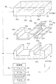
- FIG. 4 is an exploded perspective view showing an example of a configuration of a mold used for forming a fixed structure.
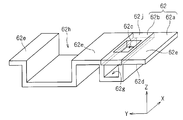
- FIG. 5 is a perspective view showing an example of the configuration of the support plate.
- FIG. 6 is a front view showing an example of a manufacturing method of a fixed structure.
- FIG. 7 is a front view showing an example of a manufacturing method of a fixed structure.
- FIG. 1 is a plan view showing an example of the configuration of the wire harness 10 according to the embodiment of the present invention.
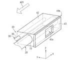
- 2 and 3 are perspective views showing an example of the configuration of the fixing structure 33 of the connector 35.
- the wire harness 10 is a bundle of a plurality of electric wires 22 and one or a plurality of electric wires 32, and is used for power supply and signal transmission / reception.
- the wire harness 10 mainly includes a main line 20, a branch line 30, and a fixing structure 33.
- FIG. 1 and the subsequent drawings have an XYZ orthogonal coordinate system in which the Z-axis direction is a vertical direction and the XY plane is a horizontal plane, as necessary, in order to clarify the directional relationship. .
- FIG. 2 is illustrated with the connector 35 omitted.
- the trunk line 20 has a plurality of electric wires 22 and electrically connects connectors 25 (25a, 25b) attached to both ends. And the connector 25 (25a, 25b) of both ends is connected with the connector (illustration omitted) of a corresponding electrical component.
- the branch line 30 has one or a plurality of electric wires 32 branched from the main line 20. As shown in FIG. 1, one end 30 a of the branch line 30 is inserted into the connector 35.
- the fixing structure 33 prevents the connector 35 from interfering with other elements by fixing the connector 35.
- the fixing structure 33 mainly includes a connector 35, a protection part 42 formed by a nonwoven fabric 41, and a fixing part 43.
- the nonwoven fabric 41 (protective material) mainly has PET (polyethylene terephthalate: base material) and a binder material formed by copolymerization of PET and PEI (polyethylene isophthalate). More specifically, the nonwoven fabric 41 mainly has basic fibers formed in a linear shape by a base material, and binder fibers in which a sheath-like binder material is arranged around the basic fibers.
- the melting point (second temperature) of the binder material is 110 to 150 ° C., which is set to be lower than the base material (the melting point of PET: about 250 ° C. (first temperature)).
- the connector 35 is an electrical component that is electrically connected to the branch line 30. As shown in FIG. 1, the connector 35 is provided at one end 30 a of one or more electric wires 32 included in the branch line 30. In the present embodiment, the connector 35 is used, for example, for connection with an electrical component (not shown) provided as an option.
- the protection part 42 is a block body having a substantially rectangular shape (square or rectangular shape) in side view. As shown in FIGS. 2 and 3, the protection part 42 surrounds a part of the electric wires 22 and 32. Thereby, the part enclosed by the protection part 42 among the electric wires 22 and 32 does not collide with another element, but is protected favorably.
- the fixing portion 43 is a sheet body having a substantially rectangular shape (square or rectangular shape) in plan view, and is integrally formed with the protection portion 42. As shown in FIG. 2, the flat surface 43a of the fixing portion 43 and the flat surface 42a of the protection portion 42 (both flat surfaces formed on the Z-axis plus side) are in a state (level) that has no step. ing.
- a holding hole 43 b is provided in the flat surface 43 a of the fixing portion 43.
- the holding hole 43b is a through hole that penetrates the fixing portion 43, and the connector 35 can be inserted into the holding hole 43b (see FIG. 1).
- the fixing portion 43 can hold the connector 35 with a simple structure called the holding hole 43b. Further, when the optional electrical component (not shown) corresponding to the connector 35 is not used and the connector 35 is not connected to another connector (not shown), the connector 35 is fixed near the main line 20 (see FIG. 1). ).
- the size (area in plan view) of the holding hole 43b is set to be smaller than the size (cross-sectional area in plan view) of the connector 35 to be inserted. Therefore, the connector 35 is satisfactorily fixed by the fixing portion 43.
- the fixing portion 43 is provided with a groove 43c adjacent to the boundary with the protection portion 42.
- the groove 43 c extends in the direction of the arrow AR ⁇ b> 1 (one direction) along the electric wires 22 and 32 protected by the protection part 42.
- FIG. 4 is a perspective view showing an example of the configuration of the mold 60 used when the fixing structure 33 is molded.
- FIG. 5 is a perspective view showing an example of the configuration of the support plate 62 included in the mold 60.
- 6 and 7 are front views showing an example of a manufacturing method of the fixing structure 33.
- the mold 60 heats and pressurizes the nonwoven fabrics 41a and 41b (see FIGS. 6 and 7), thereby forming the nonwoven fabrics 41a and 41b into a fixed structure 33 having a desired shape.
- the mold 60 mainly has a holding part 61, a support plate 62, a compression part 63, and heaters 64 (64 a and 64 b).
- the holding unit 61 is a holding element that holds the support plate 62. As shown in FIG. 4, a heater 64 a is embedded in the holding portion 61.
- the holding space 61 a is a recess formed on the upper side (Z-axis plus side: support plate 62 side) of the holding portion 61 and faces the upper surface 61 b of the holding portion 61.
- the support plate 62 is held by the holding portion 61 in a state of being fitted in the holding space 61a.
- the support plate 62 mainly includes a frame body 62a and a die 62b.
- the die 62b cooperates with the punch 63b of the compression unit 63 to execute a punching process on the fixing unit 43.
- the holding hole 43b is formed by inserting the punch 63b of the compression portion 63 into the insertion hole 62c penetrating the die 62b (see FIG. 7). (See FIGS. 2 and 3).
- the frame body 62a supports the nonwoven fabrics 41a and 41b to be heated and pressurized.
- the lower surface 62 d of the frame body 62 a is formed along the shape of the holding space 61 a of the holding portion 61. That is, the upper surface 61b of the holding part 61 and the lower surface 62d of the frame body 62a have substantially the same shape. Therefore, the support plate 62 is fitted into the holding space 61a of the holding portion 61 in a good manner.
- a punch insertion space 62g and a protection portion molding space 62h are formed on the upper side of the frame body 62a (Z-axis plus side: compression portion 63 side) except for the flat portion 62e.
- the punch insertion space 62g is a recess formed on the upper side of the frame body 62a. As shown in FIG. 5, the upper part of the punch insertion space 62g can be closed by a die 62b. Therefore, when the punching process is executed by the die 62b and the punch 63b of the compression unit 63, the punched nonwoven fabrics 41a and 41b are collected in the punch insertion space 62g.
- the protective part forming space 62h is a recess formed on the upper side of 62a, like the punch insertion space 62g.
- the compression unit 63 is a pressurizing element that applies pressure to the nonwoven fabrics 41a and 41b disposed between the compression plate 63 and the support plate 62.
- the compression part 63 mainly has a base part 63a, a punch 63b, and a convex part 63c.
- the base 63a is a substantially rectangular parallelepiped block. As shown in FIG. 4, a heater 64b is embedded in the base 63a.
- the punch 63b is a block body having a substantially rectangular shape (square or rectangular shape) when viewed from the side, and protrudes downward (Z-axis minus side: support plate 62 side) from the base 63a.
- the convex part 63c is a substantially semicircular projection in a side view and extends along the Y-axis direction.
- the nonwoven fabric 41a, 41b will be pressurized (refer FIG. 7).
- the non-woven fabric 41a, 41b is compressed by the flat lower surface 63d of the base portion 63a and the flat portions 62e, 62j of the support plate 62, so that the flat surface 42a of the protection portion 42 and the flat surface 43a of the fixing portion 43 are compressed.
- the non-woven fabrics 41a and 41b are punched out by the insertion holes 62c of the support plate 62 and the punches 63b of the compression part 63, whereby the holding holes 43b of the fixing part 43 are formed. Further, the non-woven fabric 41a, 41b is compressed by the flat portion 62e of the support plate 62 and the convex portion 63c of the compression portion 63, whereby the groove 43c of the fixing portion 43 is formed.
- the heater 64 (64a, 64b) is a heating element that heats the nonwoven fabric 41 (41a, 41b) (see FIGS. 6 and 7). As shown in FIG. 4, the heater 64 a is embedded in the bottom 61 c of the holding unit 61 and the heater 64 b is embedded in the base 63 a of the compression unit 63.
- the heater 64a when the heater 64a is driven, the holding portion 61 is heated, and the nonwoven fabric 41a is mainly heated.
- the heater 64b when the heater 64b is driven, the temperature of the compression unit 63 is increased, and the nonwoven fabric 41b is mainly heated (see FIGS. 6 and 7).
- the control unit 90 realizes, for example, heating control by the heater 64 (64a, 64b), data calculation, and the like.
- the control unit 90 mainly includes a ROM 91, a RAM 92, and a CPU 93.
- the control unit 90 is electrically connected to elements of the mold 60 (for example, heaters 64 (64 a and 64 b)) via a signal line 99.
- ROM (Read Only Memory) 91 is a so-called nonvolatile storage unit, and stores, for example, a program 91a.
- a flash memory that is a readable / writable nonvolatile memory may be used.
- a RAM (Random Access Memory) 92 is a volatile storage unit, and stores, for example, data used in the calculation of the CPU 93.
- a CPU (Central Processing Unit) 93 executes control according to the program 91a of the ROM 91 (for example, heating control of the nonwoven fabrics 41a and 41b), data calculation, and the like.
- the nonwoven fabric 41a, the trunk line 20, the branch line 30, and the nonwoven fabric 41b are arranged between the support plate 62 and the compression portion 63 in this order from above.
- the nonwoven fabric 41a and 41b are pressurized by the compression part 63 descending relative to the support plate 62. Thereby, some nonwoven fabrics 41a and 41b are accommodated in the protection part shaping
- the heater 64a of the holding unit 61 and the heater 64b of the compression unit 63 are driven by the control unit 90.
- the nonwoven fabrics 41a and 41b are heated at a temperature not lower than the melting point (second temperature) of the binder material and lower than the melting point (first temperature) of the base material.
- the protection unit 42 protects a part of the electric wires 22 and 32.
- the fixing portion 43 is integrally formed with the protection portion 42 and fixes the connector 35 provided at one end 30 a of the electric wire 32.
- the fixing portion 43 has been described as having one holding hole 43b.
- the number of the holding holes 43b is not limited to this, for example, two or more. (Multiple) may be sufficient.
- the fixing portion 43 can fix the plurality of connectors 35.
- the fixing portion 43 has been described as being bent in the groove 43c, but the processing technique in the groove 43c is not limited to this.
- the fixing portion 43 may be separated from the protection portion 42 by being cut along the groove 43 c. Also in this case, the space near the protection part 42 can be saved.
Landscapes
- Engineering & Computer Science (AREA)
- Manufacturing & Machinery (AREA)
- Details Of Indoor Wiring (AREA)
- Details Of Connecting Devices For Male And Female Coupling (AREA)
- Insulated Conductors (AREA)
Abstract
Description
図1は、本発明の実施の形態におけるワイヤーハーネス10の構成の一例を示す平面図である。図2および図3は、コネクタ35の固定構造33の構成の一例を示す斜視図である。ここで、ワイヤーハーネス10は、図1に示すように、複数の電線22、および一又は複数の電線32を束にしたものであり、電源供給および信号の送受信に使用される。図1に示すように、ワイヤーハーネス10は、主として、幹線20と、分岐線30と、固定構造33と、を有している。
図4は、固定構造33の成形時に用いられる金型60の構成の一例を示す斜視図である。図5は、金型60に含まれる支持プレート62の構成の一例を示す斜視図である。図6および図7は、固定構造33の製造方法の一例を示す正面図である。以下では、まず、金型60の構成を説明した後、保護構造33の製造方法を説明する。
ここでは、金型60のハードウェア構成について説明する。金型60は、不織布41a、41b(図6および図7参照)を加熱および加圧することによって、不織布41a、41bを所望の形状の固定構造33に成形する。図4に示すように、金型60は、主として、保持部61と、支持プレート62と、圧縮部63と、ヒータ64(64a、64b)と、を有している。
ここでは、図6および図7を参照しつつ、金型60を用いた固定構造33の製造方法について説明する。
以上のように、本実施の形態の固定構造33において、保護部42は、電線22、32の一部を保護する。また、固定部43は、保護部42と一体成形されており、電線32の一端30aに設けられたコネクタ35を固定する。
以上、本発明の実施の形態について説明してきたが、本発明は上記実施の形態に限定されるものではなく様々な変形が可能である。
20 幹線
22、32 電線
25、35 コネクタ
30 分岐線
30a 一端
33 固定構造
41(41a、41b) 不織布
42 保護部
43 固定部
43b 保持孔
43c 溝
49 接合部
60 金型
61 保持部
62 支持プレート
63 圧縮部
64(64a、64b) ヒータ
90 制御部
Claims (3)
- (a) 電線の一端に設けられたコネクタと、
(b) 前記電線の一部を囲繞する保護部と、
(c) 前記保護部と一体成形されており、前記コネクタを固定する固定部と、
を備え、
前記保護部および固定部は、
基材と、前記基材より低融点のバインダ材と、を有する保護材により成形され、
溶融した前記バインダ材が冷却凝固することによって、各々の接合部にて接合されることを特徴とするコネクタの固定構造。 - 請求項1に記載の固定構造において、
前記固定部には、前記保護部との境界に隣接する溝が設けられていることを特徴とするコネクタの固定構造。 - 請求項1に記載の固定構造において、
前記コネクタは、前記固定部に設けられた保持孔で保持されることを特徴とするコネクタの固定構造。
Priority Applications (4)
| Application Number | Priority Date | Filing Date | Title |
|---|---|---|---|
| KR1020127028332A KR20130018820A (ko) | 2010-05-17 | 2010-10-18 | 커넥터 고정구조 |
| CN2010800664924A CN102918717A (zh) | 2010-05-17 | 2010-10-18 | 连接器固定结构 |
| DE112010005577T DE112010005577T5 (de) | 2010-05-17 | 2010-10-18 | Verbinderbefestigungsstruktur |
| US13/634,626 US20130005171A1 (en) | 2010-05-17 | 2010-10-18 | Connector fixing structure |
Applications Claiming Priority (2)
| Application Number | Priority Date | Filing Date | Title |
|---|---|---|---|
| JP2010112745A JP5447173B2 (ja) | 2010-05-17 | 2010-05-17 | コネクタの固定構造 |
| JP2010-112745 | 2010-05-17 |
Publications (1)
| Publication Number | Publication Date |
|---|---|
| WO2011145231A1 true WO2011145231A1 (ja) | 2011-11-24 |
Family
ID=44991355
Family Applications (1)
| Application Number | Title | Priority Date | Filing Date |
|---|---|---|---|
| PCT/JP2010/068277 Ceased WO2011145231A1 (ja) | 2010-05-17 | 2010-10-18 | コネクタの固定構造 |
Country Status (6)
| Country | Link |
|---|---|
| US (1) | US20130005171A1 (ja) |
| JP (1) | JP5447173B2 (ja) |
| KR (1) | KR20130018820A (ja) |
| CN (1) | CN102918717A (ja) |
| DE (1) | DE112010005577T5 (ja) |
| WO (1) | WO2011145231A1 (ja) |
Cited By (1)
| Publication number | Priority date | Publication date | Assignee | Title |
|---|---|---|---|---|
| WO2013190725A1 (ja) * | 2012-06-21 | 2013-12-27 | 住友電装株式会社 | ワイヤーハーネス及びその製造方法 |
Families Citing this family (2)
| Publication number | Priority date | Publication date | Assignee | Title |
|---|---|---|---|---|
| JP5359984B2 (ja) * | 2010-04-30 | 2013-12-04 | 住友電装株式会社 | コネクタの保護構造およびその製造方法 |
| JP5796514B2 (ja) * | 2012-02-23 | 2015-10-21 | 住友電装株式会社 | ワイヤーハーネス及びワイヤーハーネスの製造方法 |
Citations (4)
| Publication number | Priority date | Publication date | Assignee | Title |
|---|---|---|---|---|
| JPS6433174U (ja) * | 1987-08-25 | 1989-03-01 | ||
| JPH0648324U (ja) * | 1992-11-24 | 1994-06-28 | 矢崎総業株式会社 | プロテクタ |
| JPH06260237A (ja) * | 1993-02-26 | 1994-09-16 | Nhk Spring Co Ltd | コネクタ構造 |
| JPH06349343A (ja) * | 1993-06-10 | 1994-12-22 | Mitsubishi Cable Ind Ltd | 分岐回路付フラットケーブル |
Family Cites Families (26)
| Publication number | Priority date | Publication date | Assignee | Title |
|---|---|---|---|---|
| US3915476A (en) * | 1975-01-16 | 1975-10-28 | Autac Inc | Electrical plug support bracket |
| US4772220A (en) * | 1987-11-12 | 1988-09-20 | Hallier Jr Martin J | Clip/bracket for trailer wiring connector |
| US5209562A (en) * | 1990-09-20 | 1993-05-11 | Glassford Joseph B | Utility light |
| US5288094A (en) * | 1992-10-23 | 1994-02-22 | Putnam Rex D | Bracket for supplying an electrical connector |
| US5308253A (en) * | 1992-10-27 | 1994-05-03 | Maki Philip J | Plug holder |
| US5648004A (en) * | 1996-04-19 | 1997-07-15 | Simpson; Claudie | Kit and method to retrofit heating elements for curling iron holder |
| JPH1126059A (ja) | 1997-07-01 | 1999-01-29 | Sumitomo Wiring Syst Ltd | オプションコネクタの保持構造 |
| US6039598A (en) * | 1998-01-26 | 2000-03-21 | Mtd Products Inc. | Electric equipment interconnection |
| GB2343911A (en) * | 1998-08-20 | 2000-05-24 | Tsai Li Hui Chou | Power cable binder mounting arrangement |
| JP3489665B2 (ja) * | 1999-04-13 | 2004-01-26 | 矢崎総業株式会社 | インパネ用ワイヤハーネス装置 |
| JP2000331751A (ja) | 1999-05-19 | 2000-11-30 | Yazaki Corp | ワイヤハーネスへのコネクタの固定構造 |
| JP4447915B2 (ja) * | 2001-11-27 | 2010-04-07 | フレニ・ブレンボ エス・ピー・エー | 電気コネクターをディスクブレーキのキャリパに固定するシステム |
| US7484689B2 (en) * | 2002-07-19 | 2009-02-03 | Illinois Tool Works Inc. | Aviation ground power unit connection system and method incorporating same |
| JP2004273369A (ja) * | 2003-03-11 | 2004-09-30 | Auto Network Gijutsu Kenkyusho:Kk | ワイヤーハーネスの伸縮規制構造およびワイヤーハーネスの布線方法 |
| US6939165B1 (en) * | 2004-07-22 | 2005-09-06 | Hon Hai Precision Ind. Co., Ltd. | Cable connector assembly with cable holder |
| US7189111B2 (en) * | 2005-05-19 | 2007-03-13 | Bae Industries, Inc. | Stand-off bracket for securing a wire harness connector assembly to DC electric motor and associated method |
| DE102005042862A1 (de) * | 2005-09-08 | 2007-03-15 | Siemens Ag | Steckverbindungen zur Anbindung von Modulen eines Kraftfahrzeugcockpits an einen Hauptleitungssatz |
| US7572133B2 (en) * | 2005-11-14 | 2009-08-11 | Cooper Technologies Company | Separable loadbreak connector and system |
| US7338314B2 (en) * | 2006-07-27 | 2008-03-04 | Ford Global Technologies, Llc | Electrical wire routing connector presenter bracket |
| US7898812B2 (en) * | 2007-01-04 | 2011-03-01 | Whirlpool Corporation | Alternative hosts for multiple adapters and multiple consumer electronic devices |
| US7494355B2 (en) * | 2007-02-20 | 2009-02-24 | Cooper Technologies Company | Thermoplastic interface and shield assembly for separable insulated connector system |
| US7963783B2 (en) * | 2008-02-25 | 2011-06-21 | Cooper Technologies Company | Separable connector system with vents in bushing nose |
| US8056226B2 (en) * | 2008-02-25 | 2011-11-15 | Cooper Technologies Company | Method of manufacturing a dual interface separable insulated connector with overmolded faraday cage |
| US8109776B2 (en) * | 2008-02-27 | 2012-02-07 | Cooper Technologies Company | Two-material separable insulated connector |
| CN103004028B (zh) * | 2010-05-21 | 2016-04-06 | 库柏技术公司 | 用于套管闭锁的适配件 |
| DE102010055851A1 (de) * | 2010-12-22 | 2012-06-28 | Harting Electronics Gmbh & Co. Kg | Steckverbinder für hohe Datenübertragungsraten |
-
2010
- 2010-05-17 JP JP2010112745A patent/JP5447173B2/ja not_active Expired - Fee Related
- 2010-10-18 US US13/634,626 patent/US20130005171A1/en not_active Abandoned
- 2010-10-18 WO PCT/JP2010/068277 patent/WO2011145231A1/ja not_active Ceased
- 2010-10-18 KR KR1020127028332A patent/KR20130018820A/ko not_active Ceased
- 2010-10-18 DE DE112010005577T patent/DE112010005577T5/de not_active Withdrawn
- 2010-10-18 CN CN2010800664924A patent/CN102918717A/zh active Pending
Patent Citations (4)
| Publication number | Priority date | Publication date | Assignee | Title |
|---|---|---|---|---|
| JPS6433174U (ja) * | 1987-08-25 | 1989-03-01 | ||
| JPH0648324U (ja) * | 1992-11-24 | 1994-06-28 | 矢崎総業株式会社 | プロテクタ |
| JPH06260237A (ja) * | 1993-02-26 | 1994-09-16 | Nhk Spring Co Ltd | コネクタ構造 |
| JPH06349343A (ja) * | 1993-06-10 | 1994-12-22 | Mitsubishi Cable Ind Ltd | 分岐回路付フラットケーブル |
Cited By (1)
| Publication number | Priority date | Publication date | Assignee | Title |
|---|---|---|---|---|
| WO2013190725A1 (ja) * | 2012-06-21 | 2013-12-27 | 住友電装株式会社 | ワイヤーハーネス及びその製造方法 |
Also Published As
| Publication number | Publication date |
|---|---|
| JP5447173B2 (ja) | 2014-03-19 |
| CN102918717A (zh) | 2013-02-06 |
| JP2011243336A (ja) | 2011-12-01 |
| US20130005171A1 (en) | 2013-01-03 |
| KR20130018820A (ko) | 2013-02-25 |
| DE112010005577T5 (de) | 2013-03-14 |
Similar Documents
| Publication | Publication Date | Title |
|---|---|---|
| JP5210463B2 (ja) | ワイヤーハーネスの製造方法 | |
| CN102741946A (zh) | 线束制造方法 | |
| JP5392171B2 (ja) | ワイヤーハーネスおよびその製造方法 | |
| KR20120135516A (ko) | 전선 보호구 | |
| EP2518735A1 (en) | Wire harness and manufacturing method for wire harness | |
| JP5644542B2 (ja) | ワイヤハーネス | |
| KR101353240B1 (ko) | 커넥터 보호 구조 및 그 제조 방법 | |
| CN103890861B (zh) | 线束以及线束的制造方法 | |
| JP5353814B2 (ja) | ワイヤーハーネスの保護構造 | |
| JP5447173B2 (ja) | コネクタの固定構造 | |
| JP5601213B2 (ja) | ワイヤハーネス | |
| CN104662756A (zh) | 线束、线束的制造方法以及保护部件 | |
| CN103824630A (zh) | 线束 | |
| JP5630343B2 (ja) | ワイヤハーネス | |
| JP2014107917A (ja) | ワイヤーハーネス | |
| JP2014003757A (ja) | 経路維持保護部材及びワイヤーハーネス | |
| JP5556606B2 (ja) | 被覆部材付電線束および被覆部材付電線束の製造方法 | |
| WO2011132336A1 (ja) | 電線結合部の保護構造 | |
| JP2015223054A (ja) | 外装部材付ワイヤーハーネス | |
| JP2013236469A (ja) | ワイヤーハーネス | |
| JP6172134B2 (ja) | ホットプレス用成形型装置及び保護部材付電線の製造方法 | |
| JP2016136796A (ja) | プロテクタ付電線及びプロテクタ付電線の製造方法 |
Legal Events
| Date | Code | Title | Description |
|---|---|---|---|
| WWE | Wipo information: entry into national phase |
Ref document number: 201080066492.4 Country of ref document: CN |
|
| 121 | Ep: the epo has been informed by wipo that ep was designated in this application |
Ref document number: 10851793 Country of ref document: EP Kind code of ref document: A1 |
|
| WWE | Wipo information: entry into national phase |
Ref document number: 13634626 Country of ref document: US |
|
| ENP | Entry into the national phase |
Ref document number: 20127028332 Country of ref document: KR Kind code of ref document: A |
|
| WWE | Wipo information: entry into national phase |
Ref document number: 9910/DELNP/2012 Country of ref document: IN |
|
| WWE | Wipo information: entry into national phase |
Ref document number: 112010005577 Country of ref document: DE Ref document number: 1120100055777 Country of ref document: DE |
|
| 122 | Ep: pct application non-entry in european phase |
Ref document number: 10851793 Country of ref document: EP Kind code of ref document: A1 |