WO2011138869A1 - 光学素子およびこれを用いた偏光フィルムの視野角改良方法 - Google Patents
光学素子およびこれを用いた偏光フィルムの視野角改良方法 Download PDFInfo
- Publication number
- WO2011138869A1 WO2011138869A1 PCT/JP2011/002541 JP2011002541W WO2011138869A1 WO 2011138869 A1 WO2011138869 A1 WO 2011138869A1 JP 2011002541 W JP2011002541 W JP 2011002541W WO 2011138869 A1 WO2011138869 A1 WO 2011138869A1
- Authority
- WO
- WIPO (PCT)
- Prior art keywords
- group
- optical element
- film
- optical
- retardation film
- Prior art date
- Legal status (The legal status is an assumption and is not a legal conclusion. Google has not performed a legal analysis and makes no representation as to the accuracy of the status listed.)
- Ceased
Links
Images


Classifications
-
- G—PHYSICS
- G02—OPTICS
- G02B—OPTICAL ELEMENTS, SYSTEMS OR APPARATUS
- G02B5/00—Optical elements other than lenses
- G02B5/30—Polarising elements
- G02B5/3083—Birefringent or phase retarding elements
-
- G—PHYSICS
- G02—OPTICS
- G02B—OPTICAL ELEMENTS, SYSTEMS OR APPARATUS
- G02B1/00—Optical elements characterised by the material of which they are made; Optical coatings for optical elements
- G02B1/04—Optical elements characterised by the material of which they are made; Optical coatings for optical elements made of organic materials, e.g. plastics
-
- G—PHYSICS
- G02—OPTICS
- G02B—OPTICAL ELEMENTS, SYSTEMS OR APPARATUS
- G02B5/00—Optical elements other than lenses
- G02B5/20—Filters
- G02B5/22—Absorbing filters
- G02B5/223—Absorbing filters containing organic substances, e.g. dyes, inks or pigments
-
- G—PHYSICS
- G02—OPTICS
- G02B—OPTICAL ELEMENTS, SYSTEMS OR APPARATUS
- G02B5/00—Optical elements other than lenses
- G02B5/30—Polarising elements
- G02B5/3025—Polarisers, i.e. arrangements capable of producing a definite output polarisation state from an unpolarised input state
- G02B5/3033—Polarisers, i.e. arrangements capable of producing a definite output polarisation state from an unpolarised input state in the form of a thin sheet or foil, e.g. Polaroid
-
- G—PHYSICS
- G02—OPTICS
- G02F—OPTICAL DEVICES OR ARRANGEMENTS FOR THE CONTROL OF LIGHT BY MODIFICATION OF THE OPTICAL PROPERTIES OF THE MEDIA OF THE ELEMENTS INVOLVED THEREIN; NON-LINEAR OPTICS; FREQUENCY-CHANGING OF LIGHT; OPTICAL LOGIC ELEMENTS; OPTICAL ANALOGUE/DIGITAL CONVERTERS
- G02F1/00—Devices or arrangements for the control of the intensity, colour, phase, polarisation or direction of light arriving from an independent light source, e.g. switching, gating or modulating; Non-linear optics
- G02F1/01—Devices or arrangements for the control of the intensity, colour, phase, polarisation or direction of light arriving from an independent light source, e.g. switching, gating or modulating; Non-linear optics for the control of the intensity, phase, polarisation or colour
- G02F1/13—Devices or arrangements for the control of the intensity, colour, phase, polarisation or direction of light arriving from an independent light source, e.g. switching, gating or modulating; Non-linear optics for the control of the intensity, phase, polarisation or colour based on liquid crystals, e.g. single liquid crystal display cells
- G02F1/133—Constructional arrangements; Operation of liquid crystal cells; Circuit arrangements
- G02F1/1333—Constructional arrangements; Manufacturing methods
- G02F1/1335—Structural association of cells with optical devices, e.g. polarisers or reflectors
- G02F1/133528—Polarisers
-
- G—PHYSICS
- G02—OPTICS
- G02F—OPTICAL DEVICES OR ARRANGEMENTS FOR THE CONTROL OF LIGHT BY MODIFICATION OF THE OPTICAL PROPERTIES OF THE MEDIA OF THE ELEMENTS INVOLVED THEREIN; NON-LINEAR OPTICS; FREQUENCY-CHANGING OF LIGHT; OPTICAL LOGIC ELEMENTS; OPTICAL ANALOGUE/DIGITAL CONVERTERS
- G02F1/00—Devices or arrangements for the control of the intensity, colour, phase, polarisation or direction of light arriving from an independent light source, e.g. switching, gating or modulating; Non-linear optics
- G02F1/01—Devices or arrangements for the control of the intensity, colour, phase, polarisation or direction of light arriving from an independent light source, e.g. switching, gating or modulating; Non-linear optics for the control of the intensity, phase, polarisation or colour
- G02F1/13—Devices or arrangements for the control of the intensity, colour, phase, polarisation or direction of light arriving from an independent light source, e.g. switching, gating or modulating; Non-linear optics for the control of the intensity, phase, polarisation or colour based on liquid crystals, e.g. single liquid crystal display cells
- G02F1/133—Constructional arrangements; Operation of liquid crystal cells; Circuit arrangements
- G02F1/1333—Constructional arrangements; Manufacturing methods
- G02F1/1335—Structural association of cells with optical devices, e.g. polarisers or reflectors
- G02F1/13363—Birefringent elements, e.g. for optical compensation
-
- G—PHYSICS
- G02—OPTICS
- G02F—OPTICAL DEVICES OR ARRANGEMENTS FOR THE CONTROL OF LIGHT BY MODIFICATION OF THE OPTICAL PROPERTIES OF THE MEDIA OF THE ELEMENTS INVOLVED THEREIN; NON-LINEAR OPTICS; FREQUENCY-CHANGING OF LIGHT; OPTICAL LOGIC ELEMENTS; OPTICAL ANALOGUE/DIGITAL CONVERTERS
- G02F1/00—Devices or arrangements for the control of the intensity, colour, phase, polarisation or direction of light arriving from an independent light source, e.g. switching, gating or modulating; Non-linear optics
- G02F1/01—Devices or arrangements for the control of the intensity, colour, phase, polarisation or direction of light arriving from an independent light source, e.g. switching, gating or modulating; Non-linear optics for the control of the intensity, phase, polarisation or colour
- G02F1/13—Devices or arrangements for the control of the intensity, colour, phase, polarisation or direction of light arriving from an independent light source, e.g. switching, gating or modulating; Non-linear optics for the control of the intensity, phase, polarisation or colour based on liquid crystals, e.g. single liquid crystal display cells
- G02F1/133—Constructional arrangements; Operation of liquid crystal cells; Circuit arrangements
- G02F1/1333—Constructional arrangements; Manufacturing methods
- G02F1/1335—Structural association of cells with optical devices, e.g. polarisers or reflectors
- G02F1/13363—Birefringent elements, e.g. for optical compensation
- G02F1/133634—Birefringent elements, e.g. for optical compensation the refractive index Nz perpendicular to the element surface being different from in-plane refractive indices Nx and Ny, e.g. biaxial or with normal optical axis
-
- G—PHYSICS
- G02—OPTICS
- G02F—OPTICAL DEVICES OR ARRANGEMENTS FOR THE CONTROL OF LIGHT BY MODIFICATION OF THE OPTICAL PROPERTIES OF THE MEDIA OF THE ELEMENTS INVOLVED THEREIN; NON-LINEAR OPTICS; FREQUENCY-CHANGING OF LIGHT; OPTICAL LOGIC ELEMENTS; OPTICAL ANALOGUE/DIGITAL CONVERTERS
- G02F2413/00—Indexing scheme related to G02F1/13363, i.e. to birefringent elements, e.g. for optical compensation, characterised by the number, position, orientation or value of the compensation plates
- G02F2413/12—Biaxial compensators
Definitions
- the present invention relates to an optical element useful for an image display device such as a liquid crystal display device and a method for improving the viewing angle of a polarizing film using the same.
- the polarizing film which is an essential member in the liquid crystal display device can be obtained, for example, as follows. First, a polyvinyl alcohol film impregnated with a water-soluble dichroic dye or a dichroic dye such as polyiodine ion is uniaxially stretched in a boric acid warm aqueous solution, or the polyvinyl alcohol film is uniaxially stretched and then dehydrated. A polarizing element is obtained by forming a polyene structure by reaction. Next, the target polarizing plate can be obtained by sandwiching the polarizing element with an adhesive using a protective film such as a triacetyl cellulose film whose surface layer has been subjected to alkali treatment or a cycloolefin polymer.
- a protective film such as a triacetyl cellulose film whose surface layer has been subjected to alkali treatment or a cycloolefin polymer.
- Patent Document 1 discloses a method of reducing the viewing angle dependency of a polarizing film using two retardation plates.
- Patent Document 1 cannot sufficiently improve the viewing angle dependency.
- colored light leaks because the wavelength dependency of the retardation film to be used can improve the viewing angle dependency of a specific wavelength but other wavelengths are insufficient.
- the wavelength dependency of the viewing angle improvement effect of the polarizing film can be effectively improved by the method as described in Patent Document 2 or Non-Patent Document 2, it is complicated that a plurality of films must be laminated. There is.
- JP 2008-310064 A Japanese Patent No. 4137438
- an object of the present invention is to provide an optical element that improves the viewing angle dependency of the polarizing element or the polarizing film and also reduces the wavelength dependency without using a plurality of films.
- the inventors of the present invention are optically anisotropic in which a three-dimensional refractive index containing at least two kinds of dichroic dyes is nx>nz> ny and an Nz coefficient is 0.2 to 0.7. It has been found that an optical element comprising a layer (retardation element) or a retardation film having the optical element on a transparent substrate is very useful for solving the above problems.
- the Nz coefficient means a value of (nx ⁇ nz) / (nx ⁇ ny).
- the present invention relates to the following inventions.
- An optical element comprising a colored and oriented optically anisotropic layer having a refractive index of nx>nz> ny and (nx ⁇ nz) / (nx ⁇ ny) of 0.2 to 0.7.
- the maximum absorption wavelength of at least one organic dye of the organic dye is 380 nm or more and less than 550 nm, and the maximum absorption wavelength of the other at least one organic dye is 550 nm or more and 780 nm or less (1) ) Optical element.
- the optically anisotropic layer includes at least one of an organic dye having a maximum absorption wavelength of 380 nm to less than 550 nm and an organic dye having a maximum absorption wavelength of 550 nm to 780 nm, an oligophenyl compound, and the following general formula:
- the optical element according to the above (1) which is a layer formed from a composition comprising the compound represented by (A),
- X represents —O—CH 2 —ph—CH 2 —O—, —O—CO—ph—CO—O— or —NH—CO—ph—CO—NH—
- ph has sulfo substitution.
- n represents the number of repetitions.
- a naphthylene group (these groups have one or two substituents selected from the group consisting of a C1-C4 alkyl group, a C1-C4 alkoxy group, a hydroxyl group and a sulfonic acid group as a substituent.
- R 21 is a hydrogen atom, a C1-C4 alkyl group, an acetyl group, a benzoyl group or a substituted or unsubstituted phenyl group
- R 23 and R 24 are each independently a hydrogen atom, a hydroxyl group, a sulfonic acid group, A C4 alkyl group or a C1-C4 alkoxy group, q represents 0 or 1, and r represents 1 or 2.
- the optical element of the present invention has a function of causing a phase difference and is useful as a phase difference element, and can be used as a phase difference film by providing the optical element on a transparent substrate film.
- the optical film having the optical element or the retardation film having the optical element on the polarizing film (hereinafter, also referred to as a polarizing film with an optical element) prevents light from leaking due to the inclination of the observation position in the liquid crystal display device.
- a polarizing film with an optical element prevents light from leaking due to the inclination of the observation position in the liquid crystal display device.
- the polarizing film with an optical element and a normal polarizing film are arranged with their absorption axes orthogonal to each other so that the optical elements are arranged between the polarizing elements, the respective absorption axis directions from the front direction Even if the observation position is tilted in a different direction, the omission of light is reduced, and even the slight leaked light is not colored, and the viewing angle dependence of the polarizing film and the wavelength dependence of the viewing angle improvement effect are also improved. It can be greatly reduced. Moreover, the viewing angle characteristic of a liquid crystal display can also be improved by using the polarizing film provided with this optical element for a liquid crystal display.
- the optical element of the present invention comprises a biaxial layer defined below containing at least two kinds of organic dyes.
- the biaxiality referred to in the present invention means that the three-dimensional refractive index satisfies the relationship of nx>nz> ny and the Nz coefficient is 0.2 to 0.7, preferably 0.3 to 0.5.
- nx is the maximum refractive index in the plane
- ny is the refractive index orthogonal to nx in the plane
- nz represents the refractive index in the vertical direction with respect to the plane.
- the Nz coefficient represents a value composed of (nx ⁇ nz) / (nx ⁇ ny).
- a method of stretching a film and a method of applying a liquid crystal composition so as to be oriented and drying to form a coating film or a coating film layer (hereinafter referred to as an orientation coating film forming method) Say).
- the method for stretching the film include the methods described in JP-A-2006-291192, WO2006 / 117981, and the like.
- Examples of the method for applying and aligning the liquid crystalline composition include the methods described in JP-T-2009-540345, W02010 / 020928, JP-A-2006-48078, JP-A-2006-316138, and the like. Is mentioned.
- the latter method for forming an oriented coating film is preferred.
- a super-compound comprising at least one polycyclic organic compound having a conjugated ⁇ system and a functional group capable of forming a non-covalent bond between supramolecules. It is preferable to use a liquid crystalline composition exhibiting lyotropic liquid crystallinity composed of supuramolecule. Examples of such polycyclic organic compounds having lyotropic liquid crystallinity include oligophenyl compounds, bibenzimidazole compounds, acetonaphthoquinosaline compounds, and triazine compounds.
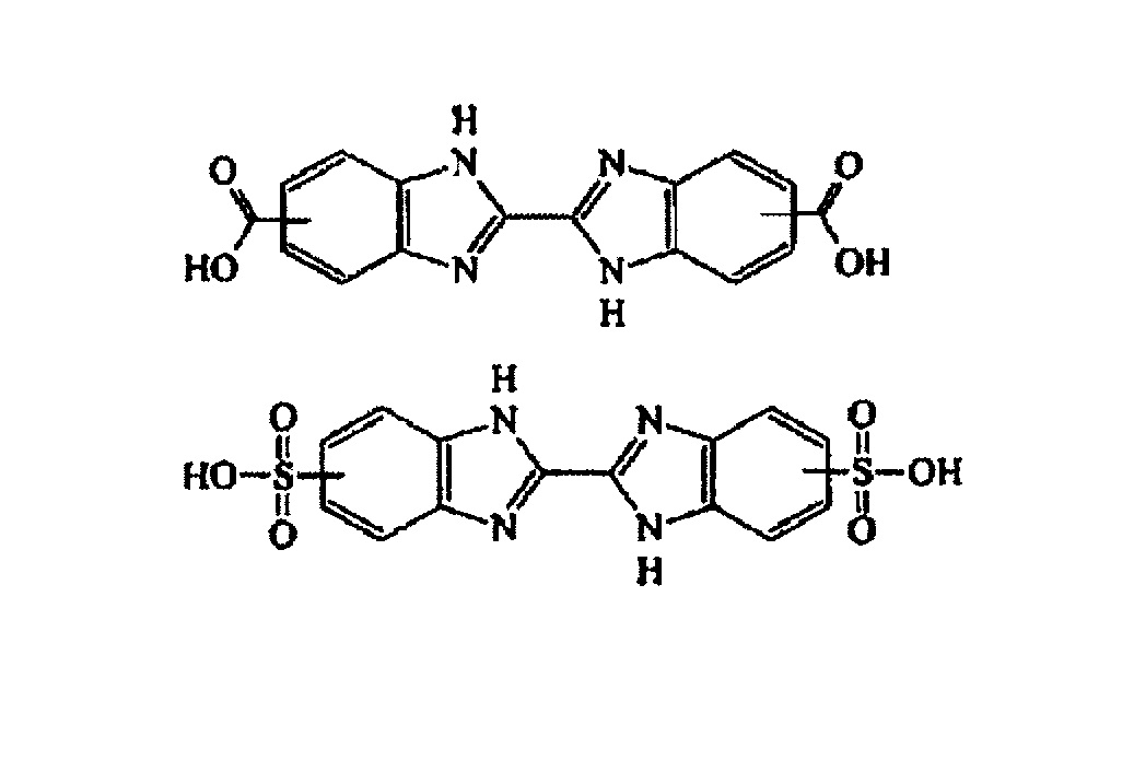
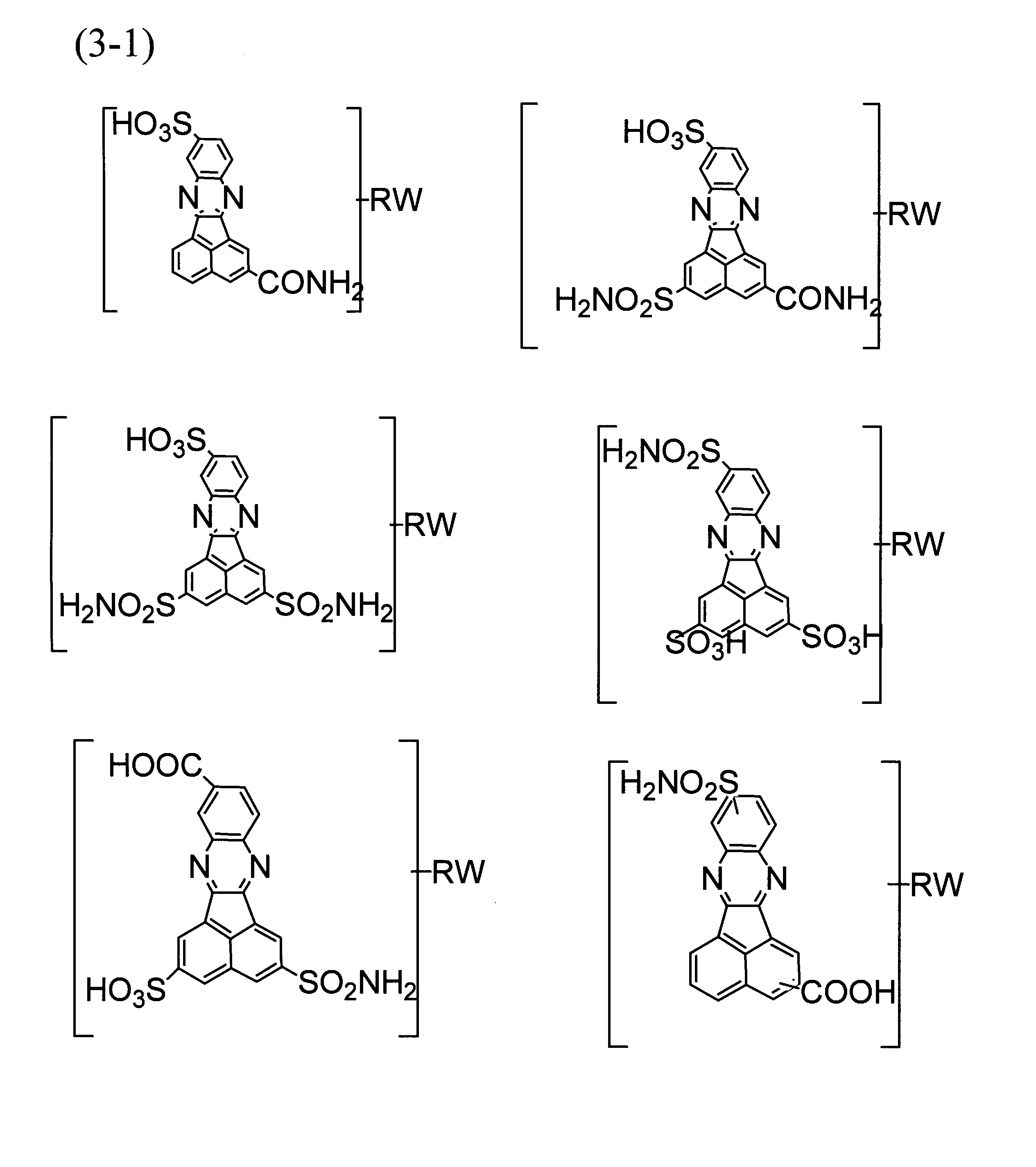
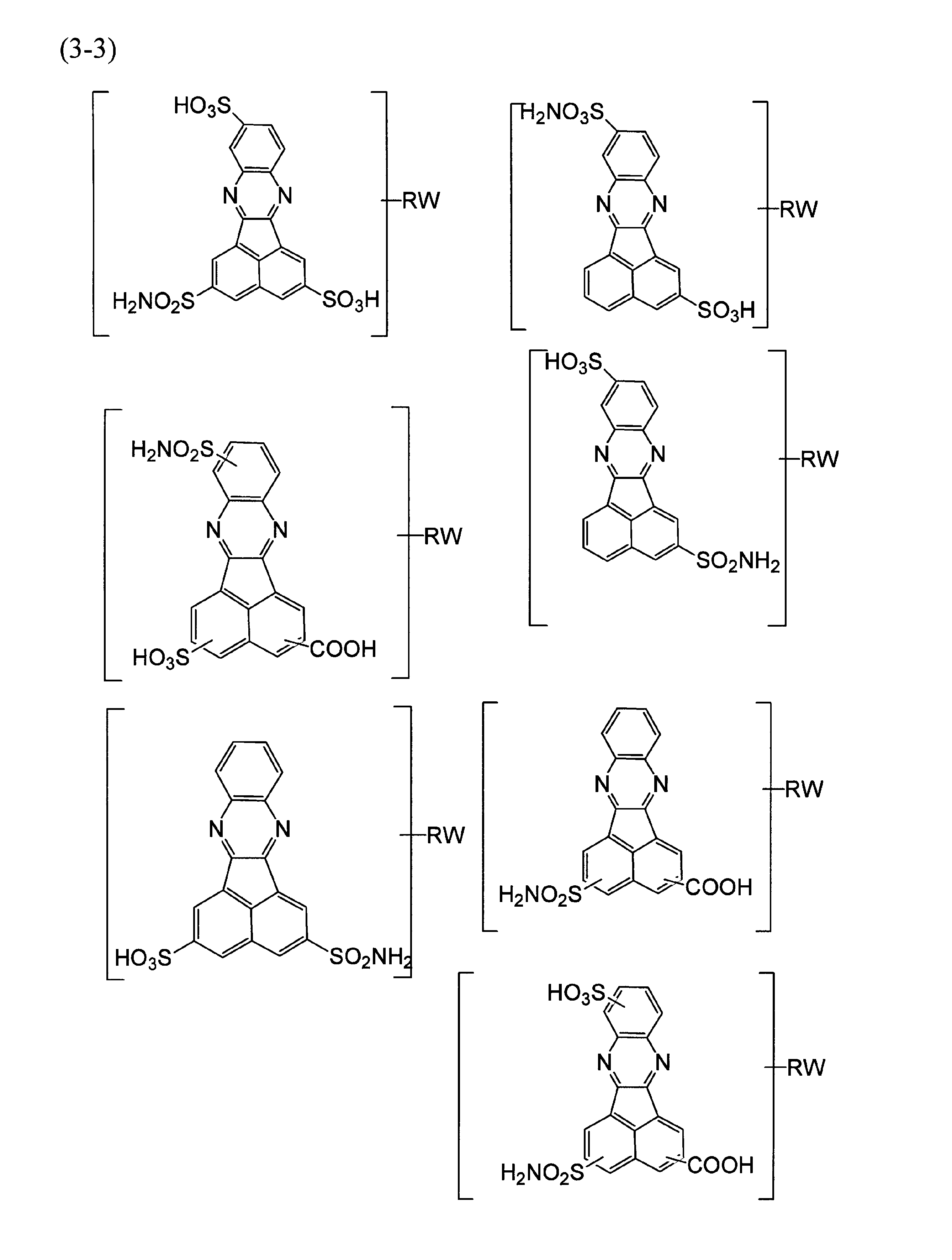
- oligophenyl compounds examples are shown in Table 1, and examples of bibenzimidazole compounds are shown in Table 2, respectively. Examples of acetonaphthoquinosaline compounds are shown in Table 3. Examples of triazine compounds are shown in Table 4.
- an oligophenyl compound is preferable.
- preferred compounds are a benzene ring, a biphenyl ring and a naphthalene ring via a 5- or 6-membered heterocyclic ring containing at least one hetero atom selected from the group consisting of an oxygen atom, a nitrogen atom and a sulfur atom. It is preferable that at least two rings selected from the group consisting of are bonded to each other, and the benzene ring, biphenyl ring or naphthalene ring preferably has one sulfo group.
- a compound represented by the following general formula (D) can be given as one preferred compound.
- Y 1 represents —O—, —NH— or —SO 2 —
- Y 2 represents a single bond, —O— or —NH—
- A1 and A2 independently represent a benzene ring, a naphthalene ring or a biphenyl ring
- the sulfo group (HSO 3 ) is substituted on those rings.
- a liquid crystal composition containing the above-mentioned liquid crystalline compound and an organic dye described later is formed on a substrate such as a film by forming a dry coating layer of the aligned liquid crystal composition on a substrate such as a film.
- a substrate having an optical element composed of an optically anisotropic layer is formed on a substrate such as a film.
- a polymer exhibiting liquid crystal properties may be added to the composition exhibiting lyotropic liquid crystal properties.
- rod-shaped liquid crystal polymers represented by WO2010 / 020928 (pages 16-17), and specific examples are shown in Table 5. It is preferable to add such a polymer exhibiting liquid crystallinity because the relationship between nx, ny, and nz of the obtained optical element can be adjusted and the durability can be improved.
- X is —O—CH 2 —ph—CH 2 —O—, —O—CO—ph—CO—O— or —NH—CO—ph—CO—NH—, and ph has sulfo-substitution.
- N represents a repeating number.
- the weight average molecular number of the liquid crystalline polymer is about 1,000 to 200,000, and preferably about 2,000 to 100,000. In some cases, the weight average molecular number may be about 3,000 to 70,000, or about 4,000 to 70,000.
- the above-mentioned two or more organic dyes, a polycyclic organic compound having lyotropic liquid crystallinity, and preferably, the liquid crystalline composition containing the above liquid crystalline polymer usually contains a solvent for forming a coating solution.
- the solvent used is not particularly limited as long as it has excellent solubility and exhibits lyotropic properties in a state where the solvent is dissolved in the composition.
- water, alcohols, ethers, cellosolves, carboxylic acids And dimethyl sulfoxide In the present invention, water is preferable from the viewpoint of handling. These can be used alone or as a mixture.
- a water-soluble solvent such as dimethylformamide, glycerin, or ethylene glycol may be added.
- the amount of the solvent is not particularly limited as long as it is a concentration at which the liquid crystalline composition can be applied.
- the solid concentration is usually 5 to 50% by weight, preferably 8 to 30% by weight, based on the total amount of the composition.
- the viscosity of the liquid crystalline composition is 200 to 1000 mPa ⁇ s when measured with an E-type viscometer at 25 ° C., it is suitable for producing a lyotropic liquid crystal. It is preferable to apply or apply a shearing force to the liquid crystal because the liquid crystal is aligned in a direction perpendicular to the MD direction.
- Examples of at least two kinds of organic dyes used in the optical element of the present invention include azo compounds, anthraquinone compounds, perylene compounds, quinophthalone compounds, naphthoquinone compounds, merocyanine compounds, and the like. Even different types of dyes will not cause any problems. Usually, the same kind of compound is preferred. More preferably, it is an azo compound showing dichroism. For example, an azo compound described in “Application of Functional Dye” (supervised by Masahiro Irie, CMC Publishing) pages 98-100, C.I. I. Direct. Yellow 28, C.I. I. Direct. Yellow 44, C.I. I. Direct. Orange 26, C.I. I. Direct. Orange 107, C.I. I. Direct.
- the at least two organic dyes used for forming the optical element or the retardation film of the present invention preferably have at least one organic dye having a maximum absorption wavelength of 380 nm or more and less than 550 nm, and the other at least one organic dye.
- the maximum absorption wavelength is 550 nm or more and 780 nm or less. More preferably, the maximum absorption wavelength of at least one organic dye (first dye) of the organic dye is 430 nm or more and 470 nm or less, and the maximum absorption wavelength of the other at least one organic dye (second dye) is 570 nm or more. It is 630 nm or less.
- the first dye include C.I. I. Direct. Orange 39, C.I. I. Direct.
- Orange 71 C.I. I. Direct. Orange 26, C.I. I. Direct.
- examples thereof include organic dyes described in Orange 107 and WO 2007/138980.
- an azo compound represented by the following general formula (B) or a salt thereof is preferable.
- X represents a sulfo group or a carboxy group
- R 1 and R 2 each independently represent a hydrogen atom, a C1-C4 alkyl group, or a C1-C4 alkoxyl group
- n represents 1 or 2.
- Examples of the second dye include C.I. I. Direct. Blue 202, C.I. I. Direct. Black 17, C.I. I. Direct. Blue 83, Direct.
- Examples thereof include organic dyes described in Green 51, Japanese Patent Application Laid-Open No. 2001-33627, and Japanese Patent No. 3963979 (0022-0027).
- Preferred examples of the dye include a compound represented by the following general formula (C) or a salt thereof.
- Q 21 represents one or two sulfonic acid groups, and further represents a naphthyl group optionally having a hydroxyl group or a C1-C4 alkoxy group
- Q 22 and Q 23 are each independently a phenylene group or A naphthylene group (these groups have one or two substituents selected from a C1 to C4 alkyl group, a C1 to C4 alkoxy group, a hydroxyl group and a sulfonic acid group as a substituent)
- R 21 is a hydrogen atom, a C1-C4 alkyl group, an acetyl group, a benzoyl group or a substituted or unsubstituted phenyl group
- R 23 and R 24 are each independently a hydrogen atom, a hydroxyl group, a sulfonic acid group, a C1-C4 alkyl group, or A C1-C4 alkoxy group
- q represents 0 or 1
- r represents
- the optical element of the present invention exhibits a remarkably excellent effect.
- a polarizing film provided with the optical element of the present invention and a normal polarizing film are arranged with their absorption axes orthogonal to each other so that the optical element is arranged between the polarizing elements, each from the front direction
- the observation position is tilted in a direction different from the absorption axis direction
- the light omission is reduced and the viewing angle dependency of the polarizing film and the effect of improving the viewing angle are reduced without coloring the slight leaked light.
- Wavelength dependence can also be greatly reduced.
- the total concentration of the above organic dyes is added to such an extent that the transmittance is not significantly reduced.
- the content is 0.01 to 10% by weight, preferably 0.1 to 5% by weight, more preferably 0.1 to 3% by weight, based on the total amount of the solid content of the coating liquid.
- the ratio of the first dye and the second dye can be selected as appropriate.
- the amount of the second dye is 0.1 to 10 parts by weight, preferably 0.
- the ratio is 2 to 5 parts by weight, more preferably 0.5 to 2 parts by weight, and most preferably 0.7 to 1.5 parts by weight.
- a liquid crystalline composition comprising the polycyclic organic compound having lyotropic liquid crystallinity and an organic dye, preferably a liquid crystalline composition further comprising the liquid crystalline polymer.
- a phase difference film can be obtained by applying an object to a transparent substrate and orienting it to form an optically anisotropic layer on the substrate.
- a liquid crystal composition may be directly applied to a polarizing film to directly form an optically anisotropic layer oriented on the polarizing film, and a polarizing film including the optical element of the present invention may be used.
- the oriented optical anisotropic layer may be first formed on a transfer substrate (releasing substrate), and the optical anisotropic layer may be transferred onto a polarizing film.
- the optically anisotropic layer is formed by being oriented in a direction perpendicular to the MD direction (Machine Direction) of the polarizing plate.
- the application method is not particularly limited as long as it can be uniformly applied and oriented. Applying to equipment using an appropriate coater such as slide coater, slot die coater, bar coater, rod coater, roll coater, curtain coater, spray coater, lip die coater, vacuum die coater, gravure coater, reverse gravure coater, micro gravure coater, etc. There is a method of spreading on a metal drum.
- a drying means for drying die coaters or gravure coaters, and in the case of gravure coaters, the use of a smoothing roll is also effective.
- the drying means There is no particular limitation on the drying means, and natural drying, vacuum drying, heat drying, vacuum heat drying and the like are used.
- the heating and drying means a drying method using an arbitrary drying apparatus such as an air circulation type drying oven or a hot roll is used.
- a preferable drying method is a method of drying at a low temperature of 0 ° C. to 40 ° C. and a relative humidity of 60% or less.
- a transparent plastic substrate or glass is usually used, and a plastic substrate is preferable.
- the plastic substrate used in the present invention include acrylic resin, polycarbonate resin, epoxy resin, and cellulose resin.
- acrylic resin polycarbonate resin
- epoxy resin epoxy resin
- cellulose resin e.g., polyethylene terephthalate (PET), polyethylene naphthalate (PEN), and syndiotactic.
- TAC triacetyl cellulose
- PET polyethylene terephthalate
- PEN polyethylene naphthalate
- SPS polystyrene
- PPS polyphenylene sulfide
- PC polycarbonate
- PAr polyacrylate
- the thickness of the substrate is not particularly limited except for the application, but is generally in the range of 1 ⁇ m to 1000 ⁇ m.
- the surface of each film is preferably subjected to surface treatment such as corona treatment, plasma treatment, alkali treatment, and primer treatment in order to adjust the wettability of the composition used in the present invention.
- the optically anisotropic layer or retardation film of the present invention has an in-plane retardation value of 130 to 300 nm at a measurement wavelength of 550 nm.
- the thickness is preferably 150 to 270 nm, more preferably 180 to 250 nm.
- the thickness of the optically anisotropic layer depends on various optical parameters such as the type of the liquid crystal cell and the in-plane retardation value, but cannot generally be said, but is usually 0.1 to 10 ⁇ m. Further, it is preferably 0.1 to 2 ⁇ m.
- the optically anisotropic layer can be subjected to a treatment for improving water resistance after film formation.
- a method of substituting with a group insoluble or hardly soluble in water using a lake agent for example, a method of substituting with a group insoluble or hardly soluble in water using a lake agent.
- the rake agent metal ions such as Ni 2+ , Ca 2+ , Fe 3+ , Cu 2+ , Zn 2+ , Al 3+ , Pd 2+ , Cd 2+ , Pb 2+ , Sn 2+ , Co 2+ , Mn 2+ , Ba 2+ , and Ce 3+ Or a salt of an organic amine.
- These rake agents may be used alone or in combination of two or more in any ratio and combination.
- Another method is to provide a protective layer on the optically anisotropic layer.
- the material used for the protective layer is not particularly limited, and examples thereof include a urethane resin, an epoxy resin, and an acrylic resin, and these may be used alone or in combination of two or more.
- a hydrophobic material is preferred, and a polyurethane resin is more preferred.
- a polyurethane resin excellent in flexibility can be laminated on the optical anisotropic layer without disturbing the orientation state of the optical anisotropic layer.
- the method of using the chelating agent and the method of providing a protective layer can be performed in combination.
- an optical anisotropic layer can be laminated on a substrate in order to obtain a desired characteristic value.
- the water resistance treatment using a chelating agent and / or the water resistance treatment for providing a protective layer may be performed for each layer or after all the optical anisotropic layers are laminated.
- the optical element or retardation film of the present invention is used in combination with a polarizing film or other retardation film.
- the optical element or the retardation film 2 is laminated so that the slow axis 4 of the retardation film 2 and the absorption axis 3 of the polarizing film 1 are orthogonal to each other.
- the optically anisotropic layer 2 is formed by directly applying to the polarizing film 1 as shown in FIG.
- the optical anisotropic layer side of the retardation film in which the optical anisotropic layer 2 is formed on the substrate is laminated with the polarizing film 1 or another retardation film via the acrylic adhesive 5.
- the optically anisotropic layer 2 formed on the base material 7 as shown in FIG. 3 is bonded to the polarizing film 1 or another retardation film via an acrylic adhesive, and the base material 7 is peeled off, so that the optically anisotropic layer 2
- the side layer 2 may be transferred to the polarizing film 1 or another retardation film.
- the retardation film of the present invention can be used by being laminated with other retardation films, and for example, it can be used in combination with a negative C plate or a positive C plate.
- any polarizing film that is usually used can be used as the polarizing film used in the production of the polarizing film with an optical element of the present invention.
- the polarizing element (polarizer) used in the polarizing film is not particularly limited as long as it is an element having a function of polarizing light from a light source and absorbs light in a specific direction to be polarized. Any reflective polarizing element that reflects light in a specific direction to be polarized can be used.
- an absorptive polarizing element for example, a polarizing element obtained by uniaxially stretching a hydrophilic polymer film such as a polyvinyl alcohol film containing a dichroic dye such as a dye or polyvalent iodine ion, a polyvinyl alcohol film A polarizing element obtained by dehydrating with an acid before and after uniaxial stretching to form a polyene structure, and a solution of a dichroic dye that develops a lyotropic liquid crystal state on an alignment film that has been processed to align in a certain direction Examples thereof include a polarizing element obtained by applying and then removing the solvent.
- a reflective polarizing element for example, a polarizing element composed of a large number of laminated bodies having different birefringence, a polarizing element formed by combining a cholesteric liquid crystal having a selective reflection region and a quarter wavelength plate, and a substrate
- a polarizing element provided with a fine wire grid.
- a hydrophilic polymer such as a polyvinyl alcohol film containing a dichroic dye such as a dye or polyvalent iodine ion, which is excellent in polarization characteristics as a polarizing element.
- a polarizing element obtained by uniaxially stretching a film or a polarizing element obtained by forming a polyene structure by dehydration with an acid before and after uniaxial stretching of a polyvinyl alcohol film.
- the polarizing element can be manufactured by a conventional method.
- a polarizing element comprising a polyvinyl alcohol film containing a dichroic dye such as a dye and polyvalent iodine ions
- the polyvinyl alcohol film was first swollen with warm water and then the dichroic dye was dissolved.
- the polarizing element can be obtained by immersing in a dyeing tank, dyeing the film, then stretching in a uniaxial direction in a tank containing a crosslinking agent such as boric acid or borax and drying.
- Examples of the dye used for dyeing include iodine-potassium iodide aqueous solution, “Application of functional dye” (supervised by Masahiro Irie, CMC Publishing Co., Ltd.), pages 98-100, C.I. I. Direct. Yellow 12, C.I. I. Direct. Yellow 28, C.I. I. Direct. Yellow 44, C.I. I. Direct. Orange 26, C.I. I. Direct. Orange 39, C.I. I. Direct. Orange 107, C.I. I. Direct. Red2, C.I. I. Direct. Red31, C.I. I. Direct. Red 79, C.I. I. Direct. Red 81, C.I. I. Direct. Red247, C.I. I. Direct.
- Green 80 C.I. I. Direct. Green 59, and JP 2001-33627, JP 2002-296417, JP 2003-215338, WO 2004/092822, JP 2001-0564112, JP 2001-027708, JP 11-218611, JP 11-218610, Examples thereof include organic dyes described in JP-A-60-156759, JP-A-2001-33627, and JP-A-2622748. These dichroic dyes are free acids, alkali metal salts (for example, Na salts, K salts and Li salts), ammonium salts, salts of amines, or complex salts (for example, Cu complexes, Ni complexes and Co complexes). Etc.
- the performance of the polarizing element can be adjusted by the dichroism of the dichroic dye, the stretch ratio during stretching, and the like.
- the image display device of the present invention for example, a liquid crystal display device can be obtained by disposing it in combination with a polarizing plate in the light path of the image display device, for example, at least one side of the liquid crystal cell of the liquid crystal display device.
- the liquid crystal display device has various modes depending on the type of the liquid crystal cell to be used. In any case, a polarizing film provided with the optical anisotropic layer (optical element) of the present invention can be used.
- the retardation film of the present invention can be used in the apparatus. What is necessary is just to adjust the NZ coefficient and retardation value of an optically anisotropic layer (optical element) or each retardation film according to each viewing angle characteristic.
- Formulation Example 1 13.6 parts of the following compound described in JP-T-2009-540345, 2.4 parts of the following compound described in WO2010 / 020928, 84 parts of water, and 0.08 part of organic dye (CI Direct. Orange 39) described in WO2007 / 138980 and 0.08 part of organic dye described in Japanese Patent No. 3963979, Were mixed and dissolved to prepare a solution having a solid content of about 16%.
- the viscosity of the solution was 330 mPa ⁇ s as measured by an E-type viscometer at 25 ° C.
- Formulation Example 2 In the above Formulation Example 1, in place of 0.08 part of the organic dye described in Japanese Patent No. 3963799, C.I. I. Direct. A solution having a solid content of about 16% was prepared in the same manner as in Formulation Example 1 except that 0.08 part of Blue67 was used. The viscosity of the solution was 330 mPa ⁇ s as measured by an E-type viscometer at 25 ° C.
- Formulation Example 3 In the above Formulation Example 1, the organic dye C.I. I. Direct. A solution having a solid content of about 16% was prepared in the same manner as in Formulation Example 1 except that the blending of both of the organic dyes described in Orange 39 and Japanese Patent No. 3963379 was stopped. The viscosity of the solution was 330 mPa ⁇ s as measured by an E-type viscometer at 25 ° C.
- Formulation Example 4 In the above Formulation Example 1, C.I. I. Direct. A solution having a solid content of about 16% was prepared in the same manner as in Formulation Example 1 except that the blending of Orange 39 was stopped. The viscosity of the solution was 330 mPa ⁇ s as measured by an E-type viscometer at 25 ° C.
- Example 1 The solution obtained in Formulation Example 1 was applied onto iodine-based polarizing plate 1a (trade name: SKN, manufactured by Polatechno Co., Ltd.) so that the thickness after drying was 1.0 ⁇ m, and a wire bar (# 10) was used. A shear stress was applied in the MD direction, and the compressor air was sprayed and dried. Further, a 10% barium nitrate aqueous solution was sprayed onto the coated surface by spraying, and compressed air was sprayed again to form an optically anisotropic layer, thereby producing a polarizing film with an optical element (optical film) of the present invention.
- iodine-based polarizing plate 1a (trade name: SKN, manufactured by Polatechno Co., Ltd.) so that the thickness after drying was 1.0 ⁇ m, and a wire bar (# 10) was used. A shear stress was applied in the MD direction, and the compressor air was sprayed and dried. Further, a 10%
- Example 2 Using the solution prepared in Formulation Example 2 instead of the solution prepared in Formulation Example 1, a polarizing film with an optical element (optical film) of the present invention was produced in the same manner as in Example 1.
- Example 3 The solution prepared in Formulation Example 1 was applied onto a triacetylcellulose (TAC) film whose surface was alkali-treated so that the thickness after drying was 1.0 ⁇ m, and the wire bar (# 10) was used in the MD direction. Shear stress was applied, and compressor air was sprayed to dry. Further, a 10% barium nitrate aqueous solution was sprayed onto the coated surface by spraying, and compressed air was sprayed again to dry, thereby producing a retardation film having an optically anisotropic layer on the film.
- the TAC film surface of the retardation film and the iodine-based polarizing plate 1a (trade name: SKN, manufactured by Polatechno Co., Ltd.) are used.
- the acrylic adhesive 5 (product) Name: PTR-2500, manufactured by Nippon Kayaku Co., Ltd.).
- Comparative Example 1 The iodine type polarizing plate 1a (trade name: SKN, manufactured by Polatechno Co., Ltd.) having no optically anisotropic layer used in Example 1 was used as it was.
- Comparative Example 2 Using the solution prepared in Formulation Example 3 instead of the solution prepared in Formulation Example 1, the same operation as in Example 1 was performed to obtain a polarizing film having a comparative optically anisotropic layer.
- Comparative Example 3 Using the solution prepared in Formulation Example 4 instead of the solution prepared in Formulation Example 1, the same operation as in Example 1 was performed to obtain a polarizing film having a comparative optically anisotropic layer.
- nx ny nz NZ factor Example 1 1.81 1.60 1.73 0.38
- Example 2 1.80 1.60 1.73 0.35
- Example 3 1.81 1.60 1.73 0.38 Comparative Example 1 (no optical anisotropic layer) Comparative Example 2 1.80 1.59 1.73 0.33 Comparative Example 3 1.80 1.60 1.73 0.35
- the in-plane retardation value at the measurement wavelength of 550 nm in the optically anisotropic layer was as follows.
- Example 1 205nm
- Example 2 205 nm
- Example 3 215 nm Comparative Example 1 (no optical anisotropic layer) Comparative Example 2 195 nm Comparative Example 3 200nm
- the optical anisotropic layer side 2 of the optical film (polarizing film with an optical element of the present invention) on which the optical anisotropic layer obtained in Examples 1 and 2 and Example 3 is formed is an acrylic adhesive.
- 5 (trade name: PTR-2500, manufactured by Nippon Kayaku Co., Ltd.) was attached to one side of the glass plate 8.
- An iodine polarizing plate 1a (trade name: SKN, manufactured by Polatechno Co., Ltd.) is also applied to the opposite side of the glass plate 8 via an acrylic adhesive 5 (trade name: PTR-2500, manufactured by Nippon Kayaku Co., Ltd.).
- a laminated sample (optical system) for optical property test was prepared by arranging the plates 1a (trade name: SKN, manufactured by Polatechno Co., Ltd.) so that their absorption axes are orthogonal to each other. In the same manner for Comparative Examples 1 to 3, laminated samples (optical systems) for optical property tests were prepared.
- the laminated sample having the above configuration is measured from a polar angle of 0 °, an azimuth angle of 0 °, a polar angle of 50 °, and an azimuth angle of 45 °, and the visibility corrected orthogonal transmittances Yc (0,0) and Yc (50 45).
- the transmittance was measured using a spectrophotometer (U-4100, manufactured by Hitachi Spectroscopic Co., Ltd.). The black luminance in the oblique direction is better as the Yc value is smaller.
- FIG. 7 shows orthogonal transmittance waveforms for Example 1 and Comparative Examples 1 and 2. The results for Examples 1 to 3 and Comparative Examples 1 to 3 are shown in Table 6.
- the orthogonal transmittance is uniformly low at a wavelength of about 450 to 700 nm regardless of the wavelength, and as can be seen from Table 6. Further, it can be seen that the black luminance Yc value in the oblique direction is low, and there is no or very little coloration in the oblique direction.
- the slow axis of the optically anisotropic layer and the retardation film and the long side direction of the panel were made parallel.
- the absorption axis of the polarizing plate (trade name: SKN, manufactured by Polatechno Co., Ltd.) of the film formed with the optical anisotropic layer obtained in Example 1 and Example 2 bonded to the backlight side,
- the absorption axis of the surface-side polarizing plate of the cell is orthogonal.
- the obtained liquid crystal panel was used for the test.
- test liquid crystal panels were prepared.
- the obtained test liquid crystal panel was placed on a backlight to obtain a liquid crystal display device. After the black screen was displayed on the liquid crystal display device and the backlight was turned on in the dark room, after 30 minutes had elapsed, the degree of coloring was observed visually from an oblique direction (azimuth angle 45 °, polar angle 50 °). The observation results for Examples 1 to 3 and Comparative Examples 1 to 3 are shown in Table 6.
- the orthogonal transmittance can be kept low uniformly regardless of the wavelength in a wavelength range of about 450 to 700 nm without using a large number of retardation films. I can do it. Further, the black luminance in the oblique direction can be suppressed to a low level, and coloring in the oblique direction can be eliminated or significantly reduced, so that it is extremely useful as an optical element.
Landscapes
- Physics & Mathematics (AREA)
- General Physics & Mathematics (AREA)
- Optics & Photonics (AREA)
- Nonlinear Science (AREA)
- Mathematical Physics (AREA)
- Chemical & Material Sciences (AREA)
- Crystallography & Structural Chemistry (AREA)
- Polarising Elements (AREA)
- Liquid Crystal (AREA)
Abstract
Description
まず、水溶性の二色性染料や多ヨウ素イオン等の二色性色素を含浸させたポリビニルアルコールフィルムをホウ酸温水溶液中で一軸延伸するか、または、ポリビニルアルコールフィルムを一軸延伸し、次いで脱水反応により、ポリエン構造を形成させることにより偏光素子を得る。次いで、表層がアルカリ処理されたトリアセチルセルロースフィルム、または、シクロオレフィンポリマーなどの保護フィルムで、該偏光素子を、接着剤を用いて挟持することにより、目的とする偏光版を得ることが出来る。
こうした、偏光フィルムの視野角改良効果の波長依存性については、特許文献2あるいは非特許文献2にあるような方法により、効果的に改善できるものの、複数のフィルムを積層しなければならないという煩雑さがある。
例えば、該光学素子を偏光フィルム上に形成する等により、この光学素子を設けた偏光フィルムを作成し、この光学素子付き偏光フィルムと通常の偏光フィルムとを、該光学素子が偏光素子間に配置されるように、両偏光素子の吸収軸を直交させて配置した場合上記問題を解決出来ること、即ち、正面方向からの各々の吸収軸方向とは異なる方向に観察位置を傾斜させても、光の抜けが低減され、かつ、漏れたわずかな光も着色することなく、偏光フィルムの視野角依存性および視野角改善効果の波長依存性も大幅に低減できることを新規に見出し、本発明に至った。即ち本発明は、下記の発明に関する。
(2) 前記有機色素の少なくとも一つの有機色素の極大吸収波長が380nm以上550nm未満であり、他方の少なくとも一つの有機色素の極大吸収波長が550nm以上780nm以下であることを特徴とする上記(1)に記載の光学素子。
(3) 前記有機色素がアゾ系化合物、アントラキノン系化合物、ペリレン化合物、キノフタロン系化合物、ナフトキノン系化合物またはメロシアニン系化合物である上記(1)または(2)に記載の光学素子。
(4) 測定波長550nmでの、光学異方層の面内位相差値が130nm~300nmであることを特徴とする上記(1)~(3)の何れか一項に記載の光学素子。
(5) 上記(1)~(4)の何れか一項に記載の光学素子を有する位相差フィルム。
(6) 上記(1)~(4)の何れか一項に記載の光学素子または上記(5)に記載の位相差フィルムと、他の位相差フィルムとを積層した複合位相差フィルム。
(7) 他の位相差フィルムが、ネガティブCプレートまたはポジティブCプレートであることを特徴とする上記(6)に記載の複合位相差フィルム
(8) 上記(1)~(4)の何れか一項に記載の光学素子と偏光フィルムを積層してなる光学フィルム。
(9) 上記(5)に記載の位相差フィルムと偏光フィルムを積層してなる光学フィルム。
(11) 光学素子の遅相軸と偏光フィルムの吸収軸が直交になるよう積層した上記(8)に記載の光学フィルム。
(12) 位相差フィルムの遅相軸と偏光フィルムの吸収軸が直交になるよう積層した上記(9)に記載の光学フィルム。
(13) 上記(1)~(4)の何れか一項に記載の光学素子、上記(5)に記載の位相差フィルム、上記(6)または(7)に記載の複合位相差フィルム及び上記(8)~(12)の何れか一項に記載の光学フィルムからなる群から選ばれる少なくとも一つを備えてなる画像表示装置。
(14) 画像表示装置が液晶表示装置である、上記(13)に記載の画像表示装置。
(15) 光学異方層が、極大吸収波長が380nm以上550nm未満である有機色素と極大吸収波長が550nm以上780nm以下である有機色素のそれぞれを少なくとも一つずつ、オリゴフェニル化合物及び、下記一般式(A)で示される化合物とを含む組成物から形成された層である上記(1)に記載の光学素子、

式中、Xは-O-CH2-ph-CH2-O-、-O-CO-ph-CO-O-または-NH-CO-ph-CO-NH-を表し、phはスルホ置換を有してもよいパラフェニレン基を表し、nは繰り返し数を示す。
下記一般式(B)
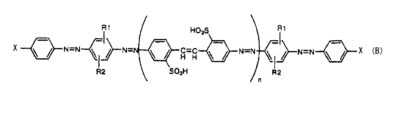
(式中Xはスルホ基またはカルボキシ基、R1、R2は各々独立に水素原子、C1~C4アルキル基、C1~C4アルコキシル基を示し、nは1または2を示す。)
で表されるアゾ化合物またはその塩を、
また、極大吸収波長が550nm以上780nm以下である有機色素として下記一般式(C)

(式中、Q21は、スルホン酸基を1個または2個有し、さらに水酸基またはC1~C4アルコキシ基を有していてもよいナフチル基を、Q22、Q23はそれぞれ独立にフェニレン基またはナフチレン基(これらの基は置換基としてC1~C4アルキル基、C1~C4アルコキシ基、水酸基およびスルホン酸基からなる群から選ばれた1種または2種の置換基を1個または2個有する)を、R21は水素原子、C1~C4アルキル基、アセチル基、ベンゾイル基または置換もしくは無置換のフェニル基を、R23、R24はそれぞれ独立に水素原子、水酸基、スルホン酸基、C1~C4アルキル基またはC1~C4アルコキシ基を、qは0または1を、rは1または2を表す。)
で表される化合物またはその塩、
を含む上記(15)に記載の光学素子。
1a.偏光フィルム
2.光学異方層
3.吸収軸
4.進相軸
5.粘着剤
6.基材
7. 離型性基材
8.ガラス板
9.測定サンプル
10.方位角θ
11.極角φ
12.正面方向(θ,φ)=(0,0)
13.φが0-180°軸
本発明の光学素子は、少なくとも2種類の有機色素を含んだ下記に定義される二軸性の層からなる。本発明で言う二軸性とは、3次元屈折率がnx>nz>nyの関係を満足し、且つNz係数が0.2~0.7、好ましくは、0.3~0.5であることを意味する。ここで、nxとは、面内の最大屈折率であり、nyとは、nxと面内で直交する屈折率であり、nzとは、面に対して鉛直方向の屈折率を表す。また、Nz係数とは、(nx-nz)/(nx-ny)からなる値を表す。この範囲外では液晶表示装置に適用したときの視野角改良などの効果が乏しくなる、もしくは斜め方向からの色付きが生じる恐れがある。
この二軸性を示すためには、フィルムを延伸させる方法と、液晶性組成物を配向するように塗布し、乾燥し、塗膜または塗膜層を形成させる方法(以下配向塗膜形成法とも言う)等が挙げられる。
フィルムを延伸する方法としては、例えば、特開2006-291192号公報、WO2006/117981号公報等に記載の方法がが挙げられる。 液晶性組成物を塗布して配向させる方法としては、例えば、特表2009-540345号公報、W02010/020928号公報、特開2006-48078号公報、特開2006-316138号公報等に記載の方法が挙げられる。
この液晶性組成物を塗布して配向させる方法の中で、共役π系と、超分子間で非共有結合を形成することが出来る官能基とを有する少なくとも1つの多環式有機化合物を含む超分子(supuramolecule)からなるリオトロピック液晶性を示す液晶性組成物を用いることが好ましい。そのようなリオトロピック液晶性を有する多環式有機化合物としては例えば、オリゴフェニル化合物、ビベンズイミダゾール化合物、アセトナフトキノサリン化合物、トリアジン化合物等が挙げられる。オリゴフェニル化合物の例を表1に、ビベンズイミダゾール化合物の例を表2にそれぞれ示す。アセトナフトキノサリン化合物の例を表3に示す。また、トリアジン化合物の例を表4に示す。
本発明においては上記リオトロピック液晶性を有する化合物のうちオリゴフェニル化合物が好ましい。オリゴフェニル化合物の中で好ましい化合物は酸素原子、窒素原子及び硫黄原子からなる群から選択される少なくとも1つの異項原子を含む5または6員複素環を介して、ベンゼン環、ビフェニル環及びナフタレン環からなる群から選択される少なくとも2個の環が結合した化合物であり、該ベンゼン環、ビフェニル環またはナフタレン環は1つのスルホ基を有するのが好ましい。

式中Y1は-O-、-NH-または-SO2-、Y2は単結合、-O-または-NH-、A1及びA2は独立に、ベンゼン環、ナフタレン環またはビフェニル環を表し、スルホ基(HSO3)はそれらの環上に置換しているものとする。
これらの化合物の中でも4,4’-(5,5’-ジオキシドジベンゾ[b,d]チエン-3,7-ジイル)ジベンゼンスルホニックアシッド(4,4'-(5,5'-dioxidodibenzo[b,d]thiene-3,7-diyl)dibenzenesulfonic acid)が好ましい。
このような化合物を含む液晶性組成物は、例えば、せん断による配向処理を行った際に、nx>nz>nyの関係を満足するように配向することを特徴とする。



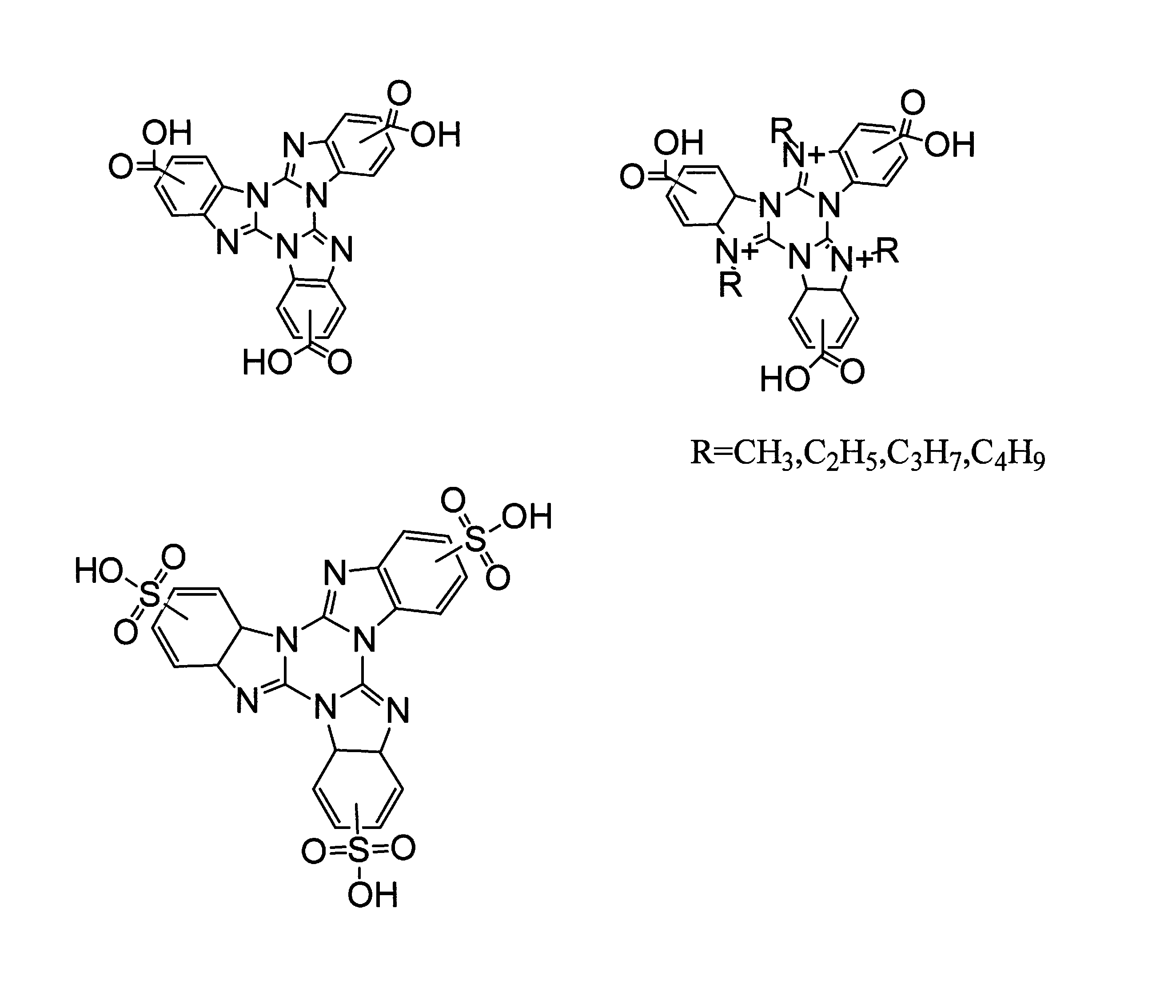
また、上記のリオトロピック液晶性を示す単数または複数の化合物の他に液晶性を示すポリマーを、リオトロピック液晶性を示す組成物に添加することも可能である。
例えば、WO2010/020928号公報(16-17頁)に代表される棒状分子の液晶ポリマーがあり、その具体例を表5に示す。このような液晶性を示すポリマーを添加することにより、得られる光学素子のnx、ny、nzの関係を調整したり、耐久性を向上させたりすることができるため好ましい。
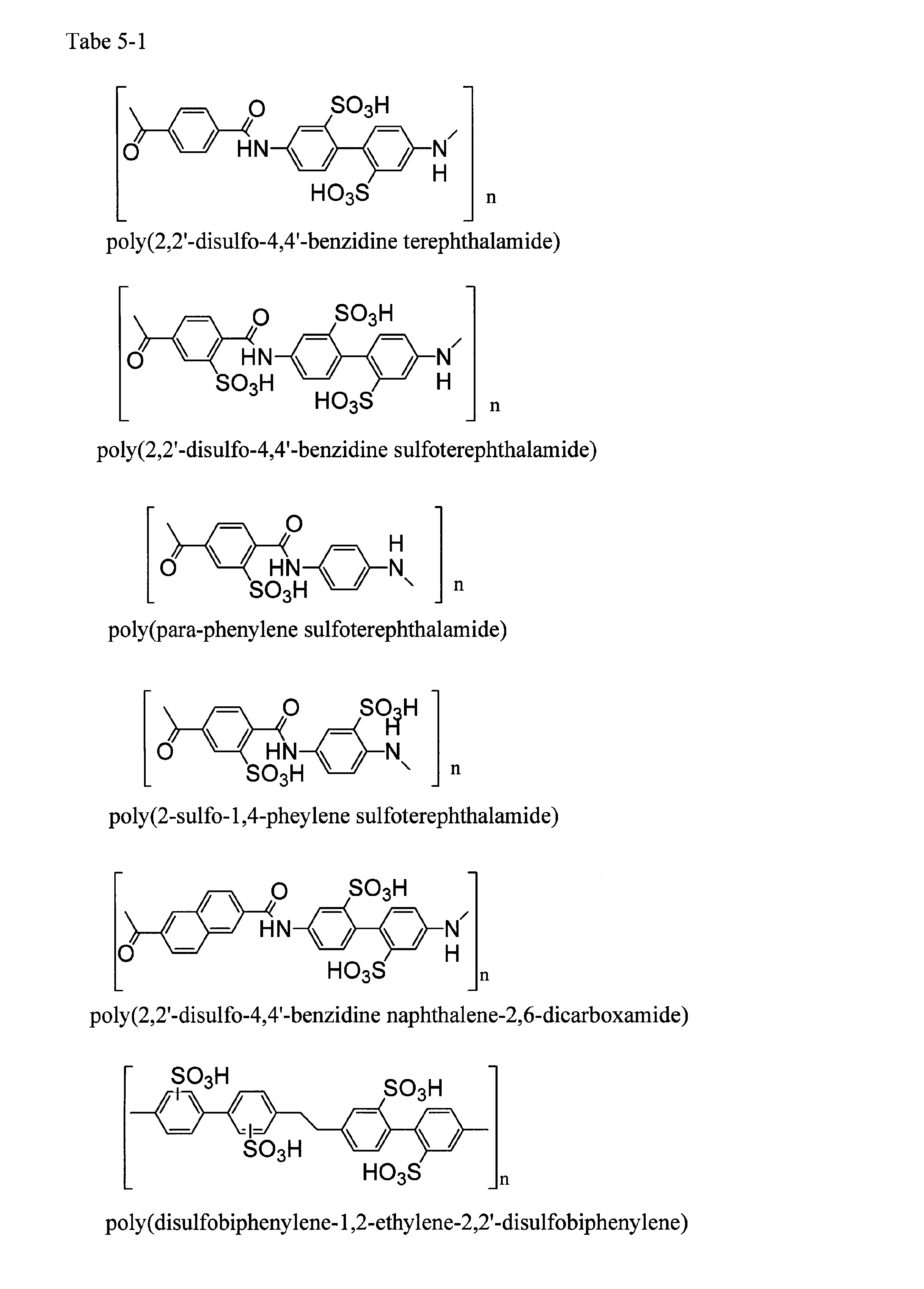


式中、Xは-O-CH2-ph-CH2-O-、-O-CO-ph-CO-O-または-NH-CO-ph-CO-NH-を、phはスルホ置換を有してもよいパラフェニレン基を、nは繰り返し数を表す。
該液晶性ポリマーの重量平均分子数は1,000~200,000程度であり、好ましくは、2,000~100,000程度である。また、場合により、該重量平均分子数は3,000~70,000程度、または4,000~70,000程度であってもよい。
溶媒の量は、該液晶性組成物を塗布することができる濃度であれば特に限定されない。例えば、溶媒を含む液晶性組成物において、該組成物の総量に対して、固形分濃度は通常5~50重量%、好ましくは8~30重量%である。
また、該液晶性組成物の粘度が、E型粘度計25℃で測定した時の粘度で200~1000mPa・sの時、リオトロピック液晶の生成に好適であり、この範囲の粘度の時、MD方向にせん断力をかけて塗布または塗工することにより、液晶の配向が、MD方向と垂直な方向に配向されるので好ましい。
中でも下記一般式(B)で表されるアゾ化合物またはその塩が好ましい。

式中Xはスルホ基またはカルボキシ基、R1、R2は各々独立に水素原子、C1~C4アルキル基、C1~C4アルコキシル基を示し、nは1または2を示す。
好ましい色素として、下記一般式(C)で表される化合物またはその塩を挙げることができる。

好ましくは、偏光板のMD方向(Machine Direction)に対して垂直方向に配向させ光学異方層を形成させる。塗布方法としては、均一に塗布し配向させられるものであれば、特に制限はない。スライドコータ、スロットダイコータ、バーコータ、ロッドコータ、ロールコータ、カーテンコータ、スプレイコータ、リップダイコータ、バキュームダイコータ、グラビアコータ、リバースグラビアコータ、マイクログラビアコータなどの適切なコータを用いて機材に塗布する方法や金属ドラムの上に展開する方法が挙げられる。好ましくは、ダイコータ類またはグラビアコータ類の使用であり、グラビアコータ類の場合にはスムージングロールの併用も有効である。乾燥手段に特に制限はなく、自然乾燥、減圧乾燥、加熱乾燥、減圧加熱乾燥などが用いられる。加熱乾燥手段としては空気循環式乾燥オーブンや熱ロールなどの任意の乾燥装置を用いた乾燥方法が用いられる。好ましい乾燥方法としては、0℃~40℃の低温で、かつ相対湿度60%以下で乾燥する方法である。
本発明の位相差フィルムは目的の特性値を得るために、基材上に光学異方層を積層することも可能である。この場合のキレート剤を用いた耐水化処理、および/または保護層を設ける耐水化処理は、各層ごとに行なっても良く、全ての光学異方層積層後に行なっても良い。
図2のように光学異方層2を基材上に形成した位相差フィルムの光学異方層側をアクリル系粘着剤5を介して偏光フィルム1もしくは他の位相差フィルムと積層する。
もしくは、図3のように基材7上に形成した光学異方層2をアクリル系粘着剤を介して偏光フィルム1もしくは他の位相差フィルムと貼合し基材7を剥離して、光学異方層2を偏光フィルム1もしくは他の位相差フィルムへ転写してもよい。
本発明の位相差フィルムは他の位相差フィルムと積層して用いることも可能であり、例えば、ネガティブCプレートまたはポジティブCプレートと組み合わせて使用することが出来る。
なお、配合例及び実施例において部は重量部を、%は重量%をそれぞれ意味する。
特表2009-540345号公報に記載の下記化合物13.6部、

WO2010/020928号公報に記載の下記化合物2.4部、

水84部、及びWO2007/138980号公報に記載の有機染料 (C.I.Direct.Orange39)0.08部及び特許第3963979号公報に記載の下記有機染料0.08部、

を均一に混合溶解し固形分が約16%の溶液を調製した。該溶液の粘度はE型粘度計25℃の測定で、330mPa・sであった。
上記配合例1において、特許3963979号公報に記載の上記有機染料0.08部の代わりに、C.I.Direct.Blue67を0.08部使用する以外は、配合例1と同様にして固形分が約16%の溶液を調製した。該溶液の粘度はE型粘度計25℃の測定で、330mPa・sであった。
上記配合例1において、有機染料のC.I.Direct.Orange39及び特許3963979号公報に記載の上記有機染料の両者の配合を止める以外は、配合例1と同様にして固形分が約16%の溶液を調製した。該溶液の粘度はE型粘度計25℃の測定で、330mPa・sであった。
上記配合例1において、有機染料としてC.I.Direct.Orange39の配合を止める以外は、配合例1と同様にして固形分が約16%の溶液を調製した。該溶液の粘度はE型粘度計25℃の測定で、330mPa・sであった。
配合例1で得られた溶液を沃素系偏光板1a(商品名:SKN、株式会社ポラテクノ製)上に乾燥後の厚みが1.0μmになるように塗布しワイヤーバー(♯10)を用いてMD方向にせん断応力をかけ、コンプレッサーエアーを噴きつけ乾燥させた。さらに、塗布面に10%硝酸バリウム水溶液を霧吹きにて吹きつけ、再度コンプレッサーエアーを噴きつけ乾燥させて光学異方層を形成し、本発明の光学素子付き偏光フィルム(光学フィルム)を作製した。
配合例1で調製した溶液の代わりに配合例2で調製した溶液を使用し、実施例1と同様にして、本発明の光学素子付き偏光フィルム(光学フィルム)を作製した。
配合例1で調製した溶液を表面をアルカリ処理をしたトリアセチルセルロース(TAC)フィルム上に乾燥後の厚みが1.0μmになるように塗布し、ワイヤーバー(♯10)を用いてMD方向にせん断応力をかけ、コンプレッサーエアーを噴きつけ乾燥させた。さらに、塗布面に10%硝酸バリウム水溶液を霧吹きにて吹きつけ、再度コンプレッサーエアーを噴きつけ乾燥させ、フィルム上に光学異方層を有する位相差フィルムを作製した。この位相差フィルムのTACフィルム面と沃素系偏光板1a(商品名:SKN、株式会社ポラテクノ製)を、位相差フィルムの遅相軸と偏光板の吸収軸が直交するようアクリル粘着剤5(商品名:PTR-2500、日本化薬株式会社製)にて貼り合せたフィルムを作製した。
実施例1で使用した光学異方層をもたない沃素系偏光板1a(商品名:SKN、株式会社ポラテクノ製)をそのまま使用した。
配合例1で調製した溶液の代わりに配合例3で調製した溶液を使用し、実施例1と同様の操作を行い、比較用の光学異方層を有する偏光フィルムを得た。
配合例1で調製した溶液の代わりに配合例4で調製した溶液を使用し、実施例1と同様の操作を行い、比較用の光学異方層を有する偏光フィルムを得た。
nx ny nz NZ係数
実施例1 1.81 1.60 1.73 0.38
実施例2 1.80 1.60 1.73 0.35
実施例3 1.81 1.60 1.73 0.38
比較例1(光学異方層無し)
比較例2 1.80 1.59 1.73 0.33
比較例3 1.80 1.60 1.73 0.35
実施例1 205nm
実施例2 205nm
実施例3 215nm
比較例1 (光学異方層無し)
比較例2 195nm
比較例3 200nm
図4に示すように実施例1~2および実施例3で得られた光学異方層を形成した光学フィルム(本発明の光学素子付き偏光フィルム)の光学異方層側2をアクリル系粘着剤5(商品名 PTR-2500、日本化薬株式会社製)を介してガラス板8の片面に貼り合わせた。ガラス板8の反対側面にも沃素系偏光板1a(商品名 SKN、株式会社ポラテクノ社製)をアクリル粘着剤5(商品名 PTR-2500、日本化薬株式会社製)を介して、沃素系偏光板1a(商品名 SKN、株式会社ポラテクノ社製)のお互いの吸収軸が直交になるように配し、光学特性試験用の積層サンプル(光学系)を作成した。また、比較例1~3についても同様にして、光学特性試験用の積層サンプル(光学系)を作成した。
本発明の光学素子を備えた液晶パネルを用いたものでは、図7から明らかな様に、波長450~700nm程度において波長によらず、直交透過率が一様に低く、かつ表6から判る様に、斜め方向の黒輝度Yc値が低く、また、斜め方向の色つきも、無いかまたは非常に少ないことが判る。
IPSモードの液晶セルを含む液晶表示装置[日立製作所株式会社製液晶テレビ 商品名「Wooo」]から、液晶パネルを取り出し、液晶セルのバックライト側に配置されていた光学フィルムを一部取り除いて、上記液晶セルのガラス面(表裏)を洗浄した。この液晶セルのバックライト側に、実施例1~3で得られた光学異方層を形成してなるフィルムの光学異方層側2をアクリル系粘着剤5(商品名:PTR-2500、日本化薬株式会社製)を介して貼り合わせた。貼り合わせは、光学異方層および位相差フィルムの遅相軸とパネルの長辺方向を平行にした。これにより、バックライト側に貼り合せた実施例1および実施例2で得られた光学異方層を形成してなるフィルムの偏光板(商品名:SKN、株式会社ポラテクノ製)の吸収軸と、当該セルの表面側偏光板の吸収軸は直交となる。得られた液晶パネルを試験に用いた。また、比較例1~3についても同様にして、試験用の液晶パネルを作成した。
○:少し着色あり
△:着色あり
×:大きく着色あり
上記の評価結果を下記表1に示す。
Yc(0,0) Yc(50,45) 斜め方向の色付き評価
実施例1 0.01% 0.20% ◎
実施例2 0.01% 0.27% ○
実施例3 0.01% 0.21% ◎
比較例1 0.01% 0.47% ×
比較例2 0.01% 0.30% △
比較例3 0.01% 0.28% △
Claims (16)
- 少なくとも2種の有機色素を含み、面内の最大屈折率をnx、nxと面内で直交する屈折率をny、面に対して鉛直方向の屈折率をnzとした時、3次元屈折率がnx>nz>nyで、(nx―nz)/(nx―ny)が0.2~0.7である着色及び配向された光学異方層からなる光学素子。
- 前記有機色素の少なくとも一つの有機色素の極大吸収波長が380nm以上550nm未満であり、他方の少なくとも一つの有機色素の極大吸収波長が550nm以上780nm以下であることを特徴とする請求項1に記載の光学素子。
- 前記有機色素がアゾ系化合物、アントラキノン系化合物、ペリレン化合物、キノフタロン系化合物、ナフトキノン系化合物またはメロシアニン系化合物である請求項1に記載の光学素子。
- 測定波長550nmでの、光学異方層の面内位相差値が130nm~300nmであることを特徴とする請求項1に記載の光学素子。
- 請求項1に記載の光学素子を有する位相差フィルム。
- 請求項1乃至4に記載の光学素子または請求項5に記載の位相差フィルムと他の位相差フィルムとを積層した複合位相差フィルム。
- 他の位相差フィルムが、ネガティブCプレートまたはポジティブCプレートであることを特徴とする請求項6に記載の複合位相差フィルム。
- 請求項1乃至4のいずれか1項に記載の光学素子と偏光フィルムを積層してなる光学フィルム。
- 請求項5に記載の位相差フィルムと偏光フィルムを積層してなる光学フィルム。
- 請求項6または7に記載の複合位相差フィルムと偏光フィルムを積層してなる光学フィルム。
- 光学素子の遅相軸と偏光フィルムの吸収軸が直交になるよう積層してなる請求項8に記載の光学フィルム。
- 位相差フィルムの遅相軸と偏光フィルムの吸収軸が直交になるよう積層した請求項9に記載の光学フィルム。
- 請求項1乃至45のいずれか1項に記載の光学素子、請求項5に記載の位相差フィルム、請求項6または7に記載の複合位相差フィルム及び請求項8~12の何れか一項に記載の光学フィルムからなる群から選ばれる少なくとも一つを備えてなる画像表示装置。
- 画像表示装置が液晶表示装置である、請求項13に記載の画像表示装置。
- 光学異方層が、極大吸収波長が380nm以上550nm未満である有機色素と極大吸収波長が550nm以上780nm以下である有機色素のそれぞれを少なくとも一つずつ、オリゴフェニル化合物及び、下記一般式(A)で示される化合物とを含む組成物から形成された層である請求項1に記載の光学素子、
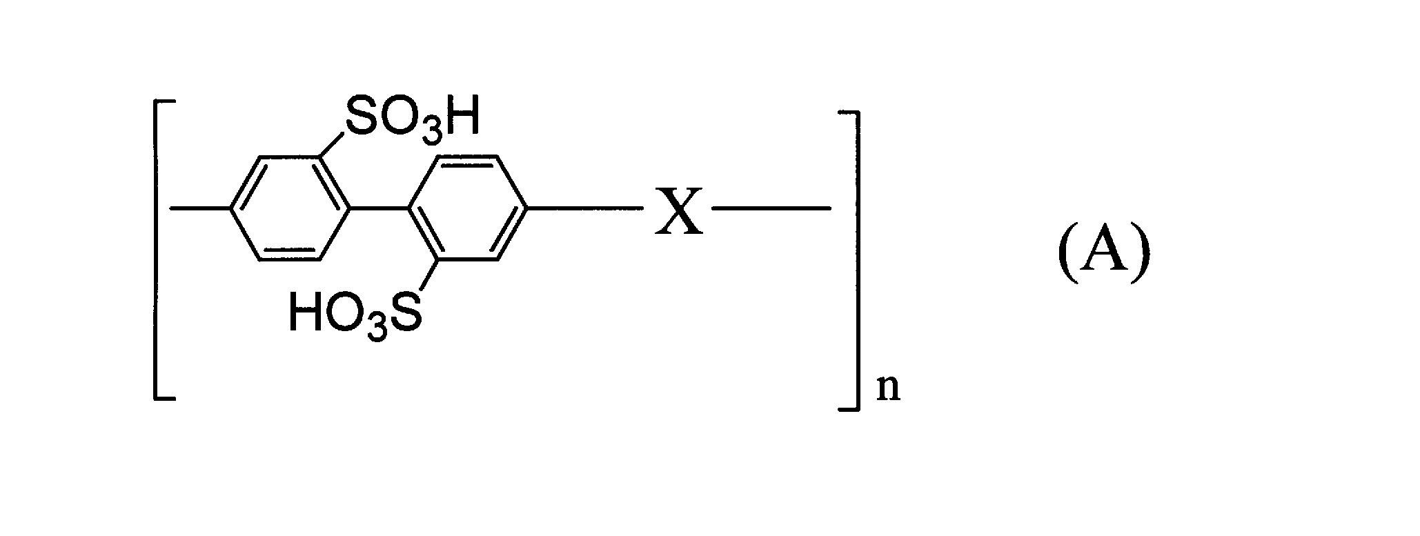
式中、Xは-O-CH2-ph-CH2-O-、-O-CO-ph-CO-O-または-NH-CO-ph-CO-NH-を表し、phはスルホ置換を有してもよいパラフェニレン基を表し、nは繰り返し数を示す。 - 極大吸収波長が380nm以上550nm未満である有機色素として、
下記一般式(B)
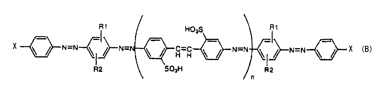
(式中Xはスルホ基またはカルボキシ基、R1、R2は各々独立に水素原子、C1~C4アルキル基、C1~C4アルコキシル基を示し、nは1または2を示す。)
で表されるアゾ化合物またはその塩を、
また、極大吸収波長が550nm以上780nm以下である有機色素として下記一般式(C)
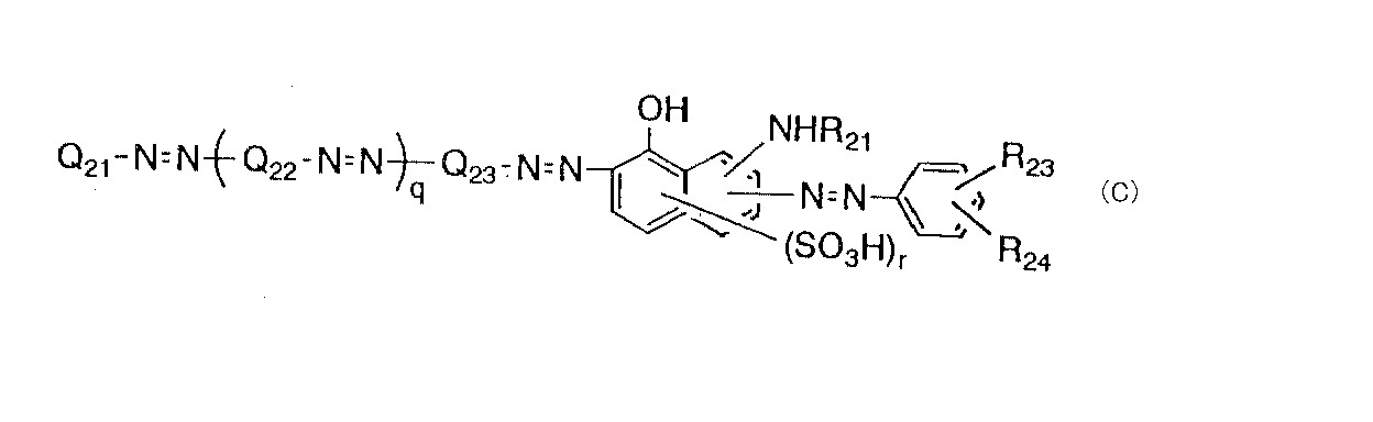
(式中、Q21は、スルホン酸基を1個または2個有し、さらに水酸基またはC1~C4アルコキシ基を有していてもよいナフチル基を、Q22、Q23はそれぞれ独立にフェニレン基またはナフチレン基(これらの基は置換基としてC1~C4アルキル基、C1~C4アルコキシ基、水酸基およびスルホン酸基からなる群から選ばれた1種または2種の置換基を1個または2個有する)を、R21は水素原子、C1~C4アルキル基、アセチル基、ベンゾイル基または置換もしくは無置換のフェニル基を、R23、R24はそれぞれ独立に水素原子、水酸基、スルホン酸基、C1~C4アルキル基またはC1~C4アルコキシ基を、qは0または1を、rは1または2を表す。)
で表される化合物またはその塩、
を含む請求項15に記載の光学素子。
Priority Applications (3)
| Application Number | Priority Date | Filing Date | Title |
|---|---|---|---|
| CN201180022769.8A CN102884456B (zh) | 2010-05-07 | 2011-05-02 | 光学元件和使用该光学元件改良偏光薄膜的视角的方法 |
| JP2012513771A JP5973911B2 (ja) | 2010-05-07 | 2011-05-02 | 光学素子、並びに、該光学素子を有する位相差フィルム、光学フィルムおよび画像表示装置 |
| KR1020127029753A KR20130080789A (ko) | 2010-05-07 | 2011-05-02 | 광학소자 및 이것을 사용한 편광필름의 시야각 개량방법 |
Applications Claiming Priority (2)
| Application Number | Priority Date | Filing Date | Title |
|---|---|---|---|
| JP2010107066 | 2010-05-07 | ||
| JP2010-107066 | 2010-05-07 |
Publications (1)
| Publication Number | Publication Date |
|---|---|
| WO2011138869A1 true WO2011138869A1 (ja) | 2011-11-10 |
Family
ID=44903722
Family Applications (1)
| Application Number | Title | Priority Date | Filing Date |
|---|---|---|---|
| PCT/JP2011/002541 Ceased WO2011138869A1 (ja) | 2010-05-07 | 2011-05-02 | 光学素子およびこれを用いた偏光フィルムの視野角改良方法 |
Country Status (5)
| Country | Link |
|---|---|
| JP (1) | JP5973911B2 (ja) |
| KR (1) | KR20130080789A (ja) |
| CN (1) | CN102884456B (ja) |
| TW (1) | TWI541529B (ja) |
| WO (1) | WO2011138869A1 (ja) |
Cited By (2)
| Publication number | Priority date | Publication date | Assignee | Title |
|---|---|---|---|---|
| WO2016190406A1 (ja) * | 2015-05-28 | 2016-12-01 | 富士フイルム株式会社 | 水平配向型液晶表示装置 |
| KR20190141124A (ko) | 2017-04-28 | 2019-12-23 | 닛토덴코 가부시키가이샤 | 액정 배향 필름 및 그의 제조 방법 |
Families Citing this family (2)
| Publication number | Priority date | Publication date | Assignee | Title |
|---|---|---|---|---|
| JP6662992B2 (ja) * | 2018-05-25 | 2020-03-11 | 住友化学株式会社 | 円偏光板の製造方法 |
| JPWO2021166907A1 (ja) * | 2020-02-17 | 2021-08-26 |
Citations (10)
| Publication number | Priority date | Publication date | Assignee | Title |
|---|---|---|---|---|
| JPH09230142A (ja) * | 1995-05-17 | 1997-09-05 | Nippon Kayaku Co Ltd | 偏光素子又は偏光板 |
| JPH11218610A (ja) * | 1998-01-30 | 1999-08-10 | Nippon Kayaku Co Ltd | 新規偏光膜 |
| JP2002071950A (ja) * | 2000-09-01 | 2002-03-12 | Nippon Kayaku Co Ltd | 光学フィルムおよびこれを用いた偏光板の視野角改良方法 |
| JP2002357720A (ja) * | 2001-03-15 | 2002-12-13 | Nippon Kayaku Co Ltd | 新規なマイクロパターン偏光素子の製造方法及びこれを用いる立体表示液晶表示装置 |
| JP2006215142A (ja) * | 2005-02-02 | 2006-08-17 | Nitto Denko Corp | 位相差フィルムおよびその製造方法、ならびに該位相差フィルムを用いた画像表示装置 |
| WO2007138980A1 (ja) * | 2006-06-01 | 2007-12-06 | Nippon Kayaku Kabushiki Kaisha | アゾ化合物及びその塩並びにそれらを含有する染料系偏光膜 |
| WO2008117347A1 (ja) * | 2007-03-22 | 2008-10-02 | Nitto Denko Corporation | 液晶パネル、それを用いた液晶表示装置、および液晶パネルの製造方法 |
| WO2009130676A2 (en) * | 2008-04-25 | 2009-10-29 | Crysoptix Kk | Color liquid crystal display and compensation panel |
| JP2009251443A (ja) * | 2008-04-09 | 2009-10-29 | Nitto Denko Corp | 積層光学フィルム、積層光学フィルムを用いた液晶パネルおよび液晶表示装置 |
| WO2010020928A2 (en) * | 2008-08-19 | 2010-02-25 | Crysoptix Kk | Composition of organic compounds, optical film and method of production thereof |
Family Cites Families (3)
| Publication number | Priority date | Publication date | Assignee | Title |
|---|---|---|---|---|
| JP4137438B2 (ja) * | 2000-12-18 | 2008-08-20 | 日本化薬株式会社 | 光学フィルムおよびこれを用いた偏光フィルム、および偏光フィルムの視野角改良方法 |
| JP4236098B2 (ja) * | 2003-08-01 | 2009-03-11 | 日東電工株式会社 | 複屈折性光学フィルム |
| JP4479928B2 (ja) * | 2007-06-15 | 2010-06-09 | 株式会社 日立ディスプレイズ | 液晶表示装置 |
-
2011
- 2011-05-02 CN CN201180022769.8A patent/CN102884456B/zh not_active Expired - Fee Related
- 2011-05-02 KR KR1020127029753A patent/KR20130080789A/ko not_active Withdrawn
- 2011-05-02 JP JP2012513771A patent/JP5973911B2/ja not_active Expired - Fee Related
- 2011-05-02 WO PCT/JP2011/002541 patent/WO2011138869A1/ja not_active Ceased
- 2011-05-06 TW TW100115904A patent/TWI541529B/zh not_active IP Right Cessation
Patent Citations (10)
| Publication number | Priority date | Publication date | Assignee | Title |
|---|---|---|---|---|
| JPH09230142A (ja) * | 1995-05-17 | 1997-09-05 | Nippon Kayaku Co Ltd | 偏光素子又は偏光板 |
| JPH11218610A (ja) * | 1998-01-30 | 1999-08-10 | Nippon Kayaku Co Ltd | 新規偏光膜 |
| JP2002071950A (ja) * | 2000-09-01 | 2002-03-12 | Nippon Kayaku Co Ltd | 光学フィルムおよびこれを用いた偏光板の視野角改良方法 |
| JP2002357720A (ja) * | 2001-03-15 | 2002-12-13 | Nippon Kayaku Co Ltd | 新規なマイクロパターン偏光素子の製造方法及びこれを用いる立体表示液晶表示装置 |
| JP2006215142A (ja) * | 2005-02-02 | 2006-08-17 | Nitto Denko Corp | 位相差フィルムおよびその製造方法、ならびに該位相差フィルムを用いた画像表示装置 |
| WO2007138980A1 (ja) * | 2006-06-01 | 2007-12-06 | Nippon Kayaku Kabushiki Kaisha | アゾ化合物及びその塩並びにそれらを含有する染料系偏光膜 |
| WO2008117347A1 (ja) * | 2007-03-22 | 2008-10-02 | Nitto Denko Corporation | 液晶パネル、それを用いた液晶表示装置、および液晶パネルの製造方法 |
| JP2009251443A (ja) * | 2008-04-09 | 2009-10-29 | Nitto Denko Corp | 積層光学フィルム、積層光学フィルムを用いた液晶パネルおよび液晶表示装置 |
| WO2009130676A2 (en) * | 2008-04-25 | 2009-10-29 | Crysoptix Kk | Color liquid crystal display and compensation panel |
| WO2010020928A2 (en) * | 2008-08-19 | 2010-02-25 | Crysoptix Kk | Composition of organic compounds, optical film and method of production thereof |
Cited By (4)
| Publication number | Priority date | Publication date | Assignee | Title |
|---|---|---|---|---|
| WO2016190406A1 (ja) * | 2015-05-28 | 2016-12-01 | 富士フイルム株式会社 | 水平配向型液晶表示装置 |
| JPWO2016190406A1 (ja) * | 2015-05-28 | 2018-03-15 | 富士フイルム株式会社 | 水平配向型液晶表示装置 |
| US10481435B2 (en) | 2015-05-28 | 2019-11-19 | Fujifilm Corporation | Horizontal alignment-type liquid crystal display device |
| KR20190141124A (ko) | 2017-04-28 | 2019-12-23 | 닛토덴코 가부시키가이샤 | 액정 배향 필름 및 그의 제조 방법 |
Also Published As
| Publication number | Publication date |
|---|---|
| CN102884456B (zh) | 2014-12-31 |
| KR20130080789A (ko) | 2013-07-15 |
| TW201200899A (en) | 2012-01-01 |
| CN102884456A (zh) | 2013-01-16 |
| JPWO2011138869A1 (ja) | 2013-07-22 |
| JP5973911B2 (ja) | 2016-08-23 |
| TWI541529B (zh) | 2016-07-11 |
Similar Documents
| Publication | Publication Date | Title |
|---|---|---|
| US9086542B2 (en) | Laminated polarizing plate, method for production thereof and liquid crystal display | |
| KR102783790B1 (ko) | 화상 표시 장치 및 상기 화상 표시 장치에 사용되는 원편광판 | |
| TWI858013B (zh) | 偏光板及其製造方法、以及使用該偏光板之影像顯示裝置 | |
| JP5723077B1 (ja) | 位相差板、楕円偏光板およびそれを用いた表示装置 | |
| CN106030354A (zh) | 投影装置及车 | |
| WO2014162635A1 (ja) | 高透過率を有する無彩色な染料系偏光素子及び偏光板 | |
| US20150293391A1 (en) | Brightness enhancement film, polarizing plate and image display device | |
| TW202030520A (zh) | 抬頭顯示器裝置及其製造方法 | |
| WO2014162634A1 (ja) | 無彩色な染料系偏光素子、及び偏光板 | |
| JP5973911B2 (ja) | 光学素子、並びに、該光学素子を有する位相差フィルム、光学フィルムおよび画像表示装置 | |
| KR100950503B1 (ko) | 이색성비가 향상된 편광판 및 이를 구비하는 액정표시장치 | |
| WO2021014685A1 (ja) | 薄型円偏光板の製造方法 | |
| TW202037680A (zh) | 抬頭顯示器裝置及其製造方法 | |
| CN110908030A (zh) | 圆偏光板及其制备方法,显示器 | |
| JP5942318B2 (ja) | 偏光フィルム、画像表示装置、及び偏光フィルムの製造方法 | |
| KR102170099B1 (ko) | 이방성 색소막용 조성물, 이방성 색소막 및 광학 소자 | |
| JP2012203002A (ja) | 偏光子及びその製造方法 | |
| TWI412843B (zh) | 光學補償膜、偏光板及液晶顯示裝置 | |
| WO2023163119A1 (ja) | 反射防止フィルムおよび有機エレクトロルミネッセンス表示装置 | |
| JP4484996B2 (ja) | 多軸偏光子の製造方法 | |
| JP2007121996A (ja) | 光学補償シートならびに、これを用いた偏光板および液晶表示装置 | |
| JP5978529B2 (ja) | 偏光フィルム、画像表示装置、及び偏光フィルムの製造方法 | |
| KR20070102964A (ko) | 광학 보상 시트, 그리고 이것을 사용한 편광판 및 액정표시 장치 | |
| KR102135497B1 (ko) | 편광판 및 이를 포함하는 액정 표시 장치 | |
| JP2023075790A (ja) | 位相差層付偏光板およびそれを用いた画像表示装置 |
Legal Events
| Date | Code | Title | Description |
|---|---|---|---|
| WWE | Wipo information: entry into national phase |
Ref document number: 201180022769.8 Country of ref document: CN |
|
| 121 | Ep: the epo has been informed by wipo that ep was designated in this application |
Ref document number: 11777389 Country of ref document: EP Kind code of ref document: A1 |
|
| WWE | Wipo information: entry into national phase |
Ref document number: 2012513771 Country of ref document: JP |
|
| NENP | Non-entry into the national phase |
Ref country code: DE |
|
| ENP | Entry into the national phase |
Ref document number: 20127029753 Country of ref document: KR Kind code of ref document: A |
|
| 122 | Ep: pct application non-entry in european phase |
Ref document number: 11777389 Country of ref document: EP Kind code of ref document: A1 |