WO2011132785A1 - 溶融ガラスの減圧脱泡方法 - Google Patents
溶融ガラスの減圧脱泡方法 Download PDFInfo
- Publication number
- WO2011132785A1 WO2011132785A1 PCT/JP2011/059981 JP2011059981W WO2011132785A1 WO 2011132785 A1 WO2011132785 A1 WO 2011132785A1 JP 2011059981 W JP2011059981 W JP 2011059981W WO 2011132785 A1 WO2011132785 A1 WO 2011132785A1
- Authority
- WO
- WIPO (PCT)
- Prior art keywords
- molten glass
- glass
- vacuum degassing
- tank
- vacuum
- Prior art date
- Legal status (The legal status is an assumption and is not a legal conclusion. Google has not performed a legal analysis and makes no representation as to the accuracy of the status listed.)
- Ceased
Links
Images


Classifications
-
- C—CHEMISTRY; METALLURGY
- C03—GLASS; MINERAL OR SLAG WOOL
- C03B—MANUFACTURE, SHAPING, OR SUPPLEMENTARY PROCESSES
- C03B5/00—Melting in furnaces; Furnaces so far as specially adapted for glass manufacture
- C03B5/16—Special features of the melting process; Auxiliary means specially adapted for glass-melting furnaces
- C03B5/225—Refining
- C03B5/2252—Refining under reduced pressure, e.g. with vacuum refiners
-
- C—CHEMISTRY; METALLURGY
- C03—GLASS; MINERAL OR SLAG WOOL
- C03C—CHEMICAL COMPOSITION OF GLASSES, GLAZES OR VITREOUS ENAMELS; SURFACE TREATMENT OF GLASS; SURFACE TREATMENT OF FIBRES OR FILAMENTS MADE FROM GLASS, MINERALS OR SLAGS; JOINING GLASS TO GLASS OR OTHER MATERIALS
- C03C3/00—Glass compositions
- C03C3/04—Glass compositions containing silica
- C03C3/076—Glass compositions containing silica with 40% to 90% silica, by weight
- C03C3/083—Glass compositions containing silica with 40% to 90% silica, by weight containing aluminium oxide or an iron compound
- C03C3/085—Glass compositions containing silica with 40% to 90% silica, by weight containing aluminium oxide or an iron compound containing an oxide of a divalent metal
-
- C—CHEMISTRY; METALLURGY
- C03—GLASS; MINERAL OR SLAG WOOL
- C03C—CHEMICAL COMPOSITION OF GLASSES, GLAZES OR VITREOUS ENAMELS; SURFACE TREATMENT OF GLASS; SURFACE TREATMENT OF FIBRES OR FILAMENTS MADE FROM GLASS, MINERALS OR SLAGS; JOINING GLASS TO GLASS OR OTHER MATERIALS
- C03C3/00—Glass compositions
- C03C3/04—Glass compositions containing silica
- C03C3/076—Glass compositions containing silica with 40% to 90% silica, by weight
- C03C3/089—Glass compositions containing silica with 40% to 90% silica, by weight containing boron
- C03C3/091—Glass compositions containing silica with 40% to 90% silica, by weight containing boron containing aluminium
-
- G—PHYSICS
- G02—OPTICS
- G02F—OPTICAL DEVICES OR ARRANGEMENTS FOR THE CONTROL OF LIGHT BY MODIFICATION OF THE OPTICAL PROPERTIES OF THE MEDIA OF THE ELEMENTS INVOLVED THEREIN; NON-LINEAR OPTICS; FREQUENCY-CHANGING OF LIGHT; OPTICAL LOGIC ELEMENTS; OPTICAL ANALOGUE/DIGITAL CONVERTERS
- G02F1/00—Devices or arrangements for the control of the intensity, colour, phase, polarisation or direction of light arriving from an independent light source, e.g. switching, gating or modulating; Non-linear optics
- G02F1/01—Devices or arrangements for the control of the intensity, colour, phase, polarisation or direction of light arriving from an independent light source, e.g. switching, gating or modulating; Non-linear optics for the control of the intensity, phase, polarisation or colour
- G02F1/13—Devices or arrangements for the control of the intensity, colour, phase, polarisation or direction of light arriving from an independent light source, e.g. switching, gating or modulating; Non-linear optics for the control of the intensity, phase, polarisation or colour based on liquid crystals, e.g. single liquid crystal display cells
-
- Y—GENERAL TAGGING OF NEW TECHNOLOGICAL DEVELOPMENTS; GENERAL TAGGING OF CROSS-SECTIONAL TECHNOLOGIES SPANNING OVER SEVERAL SECTIONS OF THE IPC; TECHNICAL SUBJECTS COVERED BY FORMER USPC CROSS-REFERENCE ART COLLECTIONS [XRACs] AND DIGESTS
- Y02—TECHNOLOGIES OR APPLICATIONS FOR MITIGATION OR ADAPTATION AGAINST CLIMATE CHANGE
- Y02P—CLIMATE CHANGE MITIGATION TECHNOLOGIES IN THE PRODUCTION OR PROCESSING OF GOODS
- Y02P40/00—Technologies relating to the processing of minerals
- Y02P40/50—Glass production, e.g. reusing waste heat during processing or shaping
- Y02P40/57—Improving the yield, e-g- reduction of reject rates
Definitions
- the present invention relates to a vacuum degassing method for molten glass.
- the molten glass is introduced into the reduced-pressure atmosphere, and bubbles in the molten glass flow that continuously flows under this reduced-pressure atmosphere are greatly grown to lift and remove bubbles contained in the molten glass,
- a vacuum degassing method for discharging from a vacuum atmosphere is known.
- oxide refining agents such as As 2 O 3 , Sb 2 O 3 and SnO 2
- alkali metal chloride refining agents such as NaCl, SO 3 and the like.
- As 2 O 3 and Sb 2 O 3 particularly As 2 O 3
- SnO 2 has a high oxygen releasing temperature of 1500 ° C. or higher, and it may be difficult to effectively use it as a fining agent.
- Alkali metal chloride is a clarifier that cannot be used because an alkali metal is contained in the alkali-free glass when a sufficient amount is added for clarification. For this reason, SO 3 is used as a fining agent for alkali-free glass. Since SO 3 also has an effect of improving the initial solubility of the input raw material, it is preferable as a clarifier.
- Patent Documents 1 and 2 The conditions such as pressure and temperature in the vacuum degassing tank when performing vacuum degassing are shown in Patent Documents 1 and 2, etc., but the same kind glass, specifically, the same non-alkali glass.
- the composition is different and the viscosity characteristics are different, the clarification effect in vacuum degassing is different, and the intended clarification effect may not be obtained.
- it is necessary to adjust the melting temperature of the glass according to the viscosity of the glass, and the temperature of the molten glass supplied from the melting tank to the vacuum degassing tank is also glass. Varies depending on the viscosity characteristics.
- the conditions such as the pressure and temperature in the vacuum degassing tank are conditions that exert an excellent clarification effect on a certain viscosity glass, the glass having a different composition and a different relationship between temperature and viscosity In this case, the intended clarification effect may not be obtained.
- Patent Document 3 when the glass to be produced is a soda lime glass containing moisture, from the ⁇ -OH value of the glass, the SO 3 content of the glass, and the bubble growth starting pressure derived from the temperature of the molten glass, what is soda lime glass? Even if the method described in Patent Document 3 is applied to alkali-free glasses having completely different compositions, it is considered that the intended clarification effect cannot be exhibited. Specifically, alkali-free glass has a very low solubility of SO 3 compared to soda lime glass, and thus has little influence on the clarification effect, and it is considered that the method of Patent Document 3 cannot be applied.
- the present invention provides a reduced-pressure defoaming method for alkali-free glass that can provide optimum reduced-pressure defoaming conditions for a plurality of alkali-free glasses having different viscosity characteristics.
- the purpose is to do.
- the present invention is a method for degassing molten glass by flowing molten glass into a vacuum degassing tank whose inside is maintained in a reduced pressure state,
- the molten glass is alkali-free glass
- Defoaming was performed under the conditions that the viscosity ⁇ (Pa ⁇ s) of the molten glass when passing through the vacuum degassing tank and the SO 3 concentration [SO 3 ] (ppm) of the molten glass satisfy the following formula (1)
- the present invention provides a method for degassing a molten glass under reduced pressure. 18.2 + 1003 / ⁇ ⁇ 1.05 ⁇ [SO 3 ] ⁇ 8 ...
- the SO 3 concentration [SO 3 ] (ppm) of the molten glass preferably satisfies the following formula (2).
- [SO 3 ] ⁇ 0.0775 ⁇ T max +135.02 ...
- T max is the maximum temperature (° C.) of the molten glass in the melting tank.
- the T max is T 2 ⁇ 120 ° C. to T 2 It is preferable to satisfy ⁇ 10 ° C.
- the SO 3 concentration [SO 3 ] (ppm) of the molten glass is preferably 3 to 40 ppm.
- T max which is the maximum temperature (° C.) of the molten glass in the melting tank is preferably 1400 to 1700 ° C.
- the alkali-free glass in the vacuum degassing method of the above-mentioned molten glass contains the following components by the mass% display.
- SiO 2 50 to 66%, Al 2 O 3 : 10.5-22%, B 2 O 3 : 0 to 12% MgO: 0-8%, CaO: 0 to 14.5%, SrO: 0 to 24%, BaO: 0 to 13.5%, MgO + CaO + SrO + BaO: 9-29.5%.
- the “to” indicating the numerical range described above is used in the sense of including the numerical values described before and after it as the lower limit and the upper limit, and hereinafter “to” is used with the same meaning.
- optimum vacuum degassing conditions can be given to a plurality of alkali-free glasses having different viscosity characteristics.
- the number of bubbles in the molten glass after the vacuum defoaming treatment is extremely reduced, and a high-function and high-quality glass with few bubbles can be produced.
- FIG. 1 is a cross-sectional view showing a configuration example of a vacuum degassing apparatus used in the vacuum degassing method of the present invention.
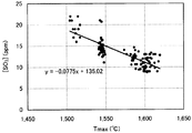
- FIG. 2 is a graph plotting the relationship between T max and [SO 3 ].
- FIG. 3 is a graph plotting the relationship between the calculated value of formula (a) and the number of bubbles (bubble density) in the glass plate.
- FIG. 1 is a cross-sectional view showing a configuration example of a vacuum degassing apparatus used in the vacuum degassing method of the present invention.
- a cylindrical vacuum degassing tank 12 is housed and disposed in the vacuum housing 11 so that its long axis is oriented in the horizontal direction.
- a rising pipe 13 oriented in the vertical direction is attached to the lower surface of one end of the vacuum degassing tank 12, and a lowering pipe 14 is attached to the lower surface of the other end.
- a part of the ascending pipe 13 and the descending pipe 14 is located in the decompression housing 11.
- the ascending pipe 13 communicates with the vacuum degassing tank 12 and introduces the molten glass G from the melting tank 20 into the vacuum degassing tank 12.
- the downcomer 14 communicates with the vacuum degassing tank 12 and guides the molten glass G after the vacuum degassing to the next processing tank (not shown).
- a heat insulating material 15 such as a heat insulating brick is provided around the decompression defoaming tank 12, the ascending pipe 13 and the descending pipe 14 to insulate these.
- the vacuum degassing tank 12 is decompressed by a vacuum suction device (not shown) through a suction hole (not shown) provided in the vacuum housing 11.
- the vacuum degassing tank 12, the rising pipe 13, and the descending pipe 14 are made of a material excellent in heat resistance and corrosion resistance against molten glass because they are conduits for molten glass. ing.
- it is made of platinum, platinum alloy, or reinforced platinum obtained by dispersing a metal oxide in platinum or platinum alloy.
- it may be made of a ceramic nonmetallic inorganic material, that is, a dense refractory. Further, a dense refractory material with platinum or a platinum alloy lined may be used.
- the molten glass G supplied from the melting tank 20 is passed through the vacuum degassing tank 12 that has been depressurized to a predetermined degree of vacuum, and vacuum degassing is performed. It is preferable that the molten glass G is continuously supplied to and discharged from the vacuum degassing tank 12.
- the flow rate of the molten glass is preferably 2 to 100 tons / day from the viewpoint of productivity.
- the molten glass G used in the vacuum degassing method of the present invention is non-alkali glass, and SO 3 is added as a fining agent.
- the amount of SO 3 added is 0.1 to 0.45 parts by mass (hereinafter referred to as “parts by mass”) with respect to 100 parts by mass of the glass mother composition raw material, which means the amount added to 100 parts by mass of the glass mother composition raw material. Preferably). If it exceeds 0.45 parts by mass, the foam layer in the dissolution tank may become excessive. Moreover, there exists a possibility that the clarification effect may become inadequate that it is less than 0.1 mass part.
- the amount of SO 3 added is more preferably 0.2 to 0.4 parts by mass.
- Such SO 3 is added to the glass matrix composition raw material as a compound such as CaSO 4 , MgSO 4 , SrSO 4 , BaSO 4 , for example.
- SO 3 added as a fining agent decomposes into SO 2 and O 2 in the molten glass as shown in the following formula.
- SO 3 ⁇ SO 2 + 1 / 2O 2 In order to homogenize the molten glass, the temperature of the molten glass in the melting tank is maintained at a high temperature. For this reason, a part of SO 2 in the molten glass is volatilized in the melting tank.
- the inventors of the present invention are a melting tank having a production rate of molten glass of 2 to 100 tons / day, and the amount of SO 3 added is 0.1 to 0.45 parts by mass.
- the maximum temperature T max (° C.) of the molten glass is the maximum temperature of the molten glass in the glass melting tank, and it varies depending on the composition of the alkali-free glass and the structure and dimensions of the melting tank used.
- T 2 (° C.) when the temperature at which the viscosity of the molten glass is 10 2 dPa ⁇ s is T 2 (° C.), T 2 ⁇ 120 ° C. to T 2 ⁇ 10 ° C., more preferably T 2 ⁇ 100 ° C. to T 2 It is set to satisfy ⁇ 30 ° C., more preferably T 2 ⁇ 90 ° C. to T 2 ⁇ 50 ° C.
- the maximum temperature T max of the molten glass is preferably 1400 to 1700 ° C.
- the concentration is typically the SO 3 concentration [SO 3 ] in the molten glass in the melting tank 20 located below the riser 13 in FIG. 1). It is preferable that it is excellent in the clarification action. If the SO 3 concentration in the molten glass is less than 3 ppm, the clarification action in the decompression tank may be insufficient. If the SO 3 concentration in the molten glass exceeds 40 ppm, bubbles may remain in the glass produced by re-boiling the molten glass during production.
- the SO 3 concentration in the molten glass is preferably 3 to 30 ppm, more preferably 3 to 20 ppm.
- Inventors of the present application perform reduced pressure defoaming treatment of molten glass using non-alkali glass having different viscosity and the amount of SO 3 added as a clarifying agent, and in a glass plate formed with molten glass after the reduced pressure defoaming treatment
- the number of bubble defects hereinafter sometimes simply referred to as “the number of bubbles in the glass plate”
- the viscosity ⁇ (Pa ⁇ s) of the molten glass when passing through the vacuum degassing tank and the It has been found that there is a correlation between the SO 3 concentration [SO 3 ] (ppm) of the molten glass and the number of bubbles in the glass plate.
- the number of bubbles in the glass plate was measured because it is difficult to measure the number of bubbles remaining in the molten glass after the vacuum degassing treatment. Since it may be considered that there is almost no fluctuation in the number of bubbles in the molten glass after the vacuum degassing treatment, the measurement result of the number of bubbles in the glass plate is almost the same as the number of bubbles remaining in the molten glass after the vacuum degassing treatment. Degree.
- FIG. 3 shows the left side of the above formula (1) (hereinafter referred to as “formula (a)”) and a glass plate (test) when the conditions of the viscosity ⁇ and the SO 3 concentration are variously changed. It is the graph which plotted the relationship with the number of bubbles (bubble density) in a sample. In addition, the decompression degree of each data in FIG.
- FIG. 3 was set to a pressure that minimizes the number of bubbles in the test sample.
- FIG. 3 shows that the number of bubbles in the glass plate is extremely reduced when the above formula (1) is satisfied.
- the curve in the figure is obtained by approximating the average value at one scale interval on the horizontal axis with a cubic polynomial.
- the requirement for the number of bubbles in the glass plate varies depending on the use of the glass plate to be produced, but in the case of a liquid crystal display substrate, it is preferably 0.25 pieces / kg or less, and preferably 0.2 pieces / kg. More preferably, it is further preferably 0.15 piece / kg or less.
- the SO 3 concentration in the molten glass when passing through the vacuum degassing tank is maintained at substantially the same level as the SO 3 concentration in the molten glass at the time of removal from the melting tank.
- the SO 3 concentration [SO 3 ] (ppm) in the molten glass discharged from the melting tank and the maximum temperature T max (° C.) of the molten glass in the melting tank, the above formula (2) is satisfied. Since there is a correlation as shown, the SO 3 concentration in the molten glass when passing through the vacuum degassing tank is determined by the maximum temperature T max (° C.) of the molten glass in the melting tank.
- the viscosity ⁇ (Pa ⁇ s) of the molten glass when passing through the vacuum degassing tank is determined by the viscosity characteristics of the glass and the temperature of the molten glass when passing through the vacuum degassing tank.
- the vacuum degassing is carried out under the conditions satisfying the above formula (1) by adjusting the temperature of the molten glass when passing through the vacuum degassing tank according to the viscosity characteristics of the glass. Therefore, optimal vacuum degassing conditions can be easily set for glasses having different viscosities.
- the temperature of the molten glass when passing through the vacuum degassing tank is 1300 to 1600 ° C. for the purpose of maintaining durability of the structural material forming the vacuum degassing tank and suppressing defects caused by the structure.
- the temperature is preferably maintained in the range, more preferably in the temperature range of 1350 to 1550 ° C., and still more preferably in the temperature range of 1370 to 1500 ° C.
- the left side of formula (1) is preferably 9 or more, and more preferably 10 or more.
- the degree of vacuum in the vacuum degassing tank is preferably maintained at 100 mmHg (13.3 kPa) to 400 mmHg (53.3 kPa), preferably 150 mmHg (20 kPa) to 300 mmHg (40 kPa). More preferably, it is retained.
- the pressure reduction degree in a pressure reduction degassing tank the pressure reduction degree of an atmospheric
- the degree of pressure reduction in the vacuum deaeration tank can be controlled by adjusting the gauge pressure of a vacuum pressure reducing means such as a vacuum pump.
- the alkali-free glass used in the vacuum defoaming method of the present invention is preferably a glass containing the following components in terms of the mass% in terms of the following oxide. SiO 2 : 50 to 66%, Al 2 O 3 : 10.5-22%, B 2 O 3 : 0 to 12% MgO: 0-8%, CaO: 0 to 14.5%, SrO: 0 to 24%, BaO: 0 to 13.5%, MgO + CaO + SrO + BaO: 9-29.5%.
- the alkali free glass which has an above-described component is a composition about the glass plate manufactured using the above-mentioned vacuum degassing method.
- composition of the molten glass in the melting tank below the riser and the composition of the glass plate produced by performing the defoaming treatment through the vacuum degassing tank are considered to be substantially unchanged with respect to each of the above components. You can hesitate. The same applies to the SO 3 concentration of SO 3 concentration and the glass plate in the molten glass.
- the SiO 2 content exceeds 66%, the solubility of the glass decreases and the glass tends to devitrify. Preferably it is 64% or less, More preferably, it is 62% or less. If it is less than 50%, the specific gravity increases, the strain point decreases, the thermal expansion coefficient increases, and the chemical resistance decreases. Preferably it is 56% or more, More preferably, it is 58% or more.
- Al 2 O 3 is a component that suppresses the phase separation of the glass and increases the strain point, and is essential. If it exceeds 22%, devitrification tends to occur, and the chemical resistance decreases. Preferably it is 21% or less, More preferably, it is 18% or less. If it is less than 10.5%, the glass tends to undergo phase separation or the strain point decreases. Preferably it is 12% or more, more preferably 15% or more.
- B 2 O 3 is not essential, but is a component that reduces the specific gravity, increases the solubility of the glass, and makes it difficult to devitrify. If it exceeds 22%, the strain point is lowered, the chemical resistance is lowered, or volatilization at the time of melting the glass becomes remarkable, so that the inhomogeneity of the glass is increased. Preferably it is 12% or less, More preferably, it is 9% or less. If it is less than 1%, the specific gravity increases, the solubility of the glass decreases, and the glass tends to devitrify, so 2% or more is desirable, preferably 4% or more, and more preferably 6% or more.
- MgO is not essential, but is a component that reduces the specific gravity and improves the solubility of the glass. If it exceeds 8%, the glass tends to undergo phase separation, devitrification tends to occur, or chemical resistance decreases. Preferably it is 6% or less, More preferably, it is 5% or less. When it contains MgO, it is preferable to make it contain 1% or more. In particular, it is preferable to contain 3% or more in order to reduce the specific gravity while maintaining the solubility.
- CaO is not essential, but can be contained up to 14.5% in order to increase the solubility of the glass and make it difficult to devitrify. If it exceeds 14.5%, the specific gravity increases, the coefficient of thermal expansion increases, and devitrification tends to occur. Preferably it is 9% or less, More preferably, it is 7% or less. When CaO is contained, it is preferable to contain 2% or more. More preferably, it is 3.5% or more.
- SrO is a component that suppresses the phase separation of glass and makes it difficult to devitrify, and is essential. If it exceeds 24%, the specific gravity increases, the coefficient of thermal expansion increases, and devitrification tends to occur. Preferably it is 12.5% or less, More preferably, it is 8.5% or less.
- BaO can be contained up to 13.5% in order to suppress phase separation of the glass and make it difficult to devitrify. If it exceeds 13.5%, the specific gravity increases and the thermal expansion coefficient becomes large. Preferably it is 2% or less, More preferably, it is 1% or less, More preferably, it is 0.1% or less. In particular, when importance is attached to the weight reduction of the glass substrate, it is preferably not contained substantially.
- the total amount of MgO, CaO, SrO, and BaO, that is, MgO + CaO + SrO + BaO is preferably in the range of 9 to 29.9%. If the total amount exceeds 29.9%, the specific gravity increases, which is not preferable.
- the solubility is inferior, which is not preferable.
- components other than those described above, for example, ZrO 2 or the like may be contained in an amount of 5% or less.
- As 2 O 3 and Sb 2 O 3 are not contained except for those inevitably mixed in as impurities or the like, that is, not substantially contained.
- a clarifying agent other than SO 3 may be used in combination.
- specific examples of other fining agents that can be used in combination include fluorine compounds, chlorine compounds, SnO 2, and the like. These other fining agents can be contained in the alkali-free glass in an amount of 2% by mass or less, preferably 1% by mass or less, more preferably 0.5% by mass or less. It has been confirmed that the effects of these fining agents other than SO 3 on the formula (1) are substantially absent by another experiment conducted by the present inventors.
- the dimension of each component of the vacuum degassing apparatus used in the vacuum degassing method of the present invention can be appropriately selected as necessary.
- the dimensions of the vacuum degassing tank can be appropriately selected according to the vacuum degassing apparatus to be used regardless of whether the vacuum degassing tank is made of platinum, platinum alloy, or dense refractory.
- the specific example of the dimension is as follows. ⁇ Length in the horizontal direction: 1-20m ⁇ Inner diameter: 0.2-3m (circular cross section)
- the wall thickness is preferably 0.5 to 4 mm.
- the decompression housing 11 is made of metal, for example, stainless steel, and has a shape and size that can accommodate a decompression deaeration tank. Regardless of whether the riser pipe 13 and the downfall pipe 14 are made of platinum, a platinum alloy, or a dense refractory, they can be appropriately selected according to the vacuum degassing apparatus to be used.
- the dimensions of the ascending pipe 13 and the descending pipe 14 can be configured as follows. ⁇ Inner diameter: 0.05 to 0.8m ⁇ Length: 0.2-6m When the ascending pipe 13 and the descending pipe 14 are made of platinum or a platinum alloy, the thickness is preferably 0.4 to 5 mm.
- Example 1 In the present Example, the degassing
- the alkali-free glass A has a composition of SiO 2 : 59.8%, Al 2 O 3 : 17.2%, B 2 O 3 : 7.8%, MgO: 3.3%, CaO: 4.1%,
- the temperature T 2 at which the viscosity of the molten glass is 10 2 dPa ⁇ s is 1657 ° C. with SrO: 7.7% and BaO: 0.1%.
- the composition of the alkali-free glass A indicates the composition of the glass plate to be produced.
- the melting tank was a melting tank having a production rate of molten glass of 20 tons / day, and the maximum temperature T max (° C.) of the molten glass in the melting tank was 1574 ° C. From this value and the above equation (2), it is estimated that the SO 3 concentration [SO 3 ] in the molten glass discharged from the melting tank is 13.0 ppm.
- the molten glass obtained by the above procedure was degassed under reduced pressure by passing it through a vacuum degassing tank having an internal degree of vacuum maintained at 21.3 kPa.
- the temperature of the molten glass when passing through the vacuum degassing tank was 1420 ° C.
- the viscosity ⁇ of the molten glass when passing through the vacuum degassing tank was 117 Pa ⁇ s. From these results, the calculated value of equation (a) on the left side of equation (1) is 13.1.
- Example 1-2 The same procedure as in Example 1 was performed except that the maximum temperature T max (° C.) of the molten glass in the melting tank was 1484 ° C. From this value and the above equation (2), it is estimated that the SO 3 concentration [SO 3 ] in the molten glass discharged from the melting tank is 20.0 ppm. The calculated value of the above formula (a) is 5.8. About the glass plate which shape
- Example 2 In the present Example, the degassing
- the alkali-free glass B has a composition of SiO 2 : 59.5%, Al 2 O 3 : 17.3%, B 2 O 3 : 8.1%, MgO: 4.7%, CaO: 5.9%,
- the temperature T 2 at which the viscosity of the molten glass is 10 2 dPa ⁇ s is 1611 ° C. with SrO: 4.5% and BaO: 0%.
- the composition of the alkali-free glass B indicates the composition of the glass plate to be produced.
- the molten glass obtained by the above procedure was degassed under reduced pressure by passing it through a vacuum degassing tank having an internal degree of vacuum maintained at 21.3 kPa.
- the temperature of the molten glass when passing through the vacuum degassing tank was 1400 ° C.
- the viscosity ⁇ of the molten glass when passing through the vacuum degassing tank was 91 Pa ⁇ s. From these results, the calculated value of the formula (a) on the left side of the formula (1) is 11.4.
- the vacuum degassing method of the present invention it is possible to give optimum vacuum degassing conditions to a plurality of alkali-free glasses having different viscosity characteristics. As a result, the number of bubbles in the molten glass after the vacuum defoaming treatment is extremely reduced, and a high-function and high-quality glass with few bubbles can be produced.
- the method of the present invention is used when manufacturing glass substrates for liquid crystal display elements, liquid crystal televisions, plasma display televisions, organic EL devices, organic EL televisions, and other various flat panel displays that are strictly required to be free from bubble defects. Is very useful.
- the entire contents of the specification, claims, drawings and abstract of Japanese Patent Application No. 2010-099611 filed on April 23, 2010 are incorporated herein as the disclosure of the present invention. .
- Depressurization degassing device 11 Depressurization housing 12: Depressurization defoaming tank 13: Rising pipe 14: Downfalling pipe 15: Thermal insulation 20: Dissolution tank
Landscapes
- Chemical & Material Sciences (AREA)
- Materials Engineering (AREA)
- Engineering & Computer Science (AREA)
- Organic Chemistry (AREA)
- Chemical Kinetics & Catalysis (AREA)
- Geochemistry & Mineralogy (AREA)
- General Chemical & Material Sciences (AREA)
- Life Sciences & Earth Sciences (AREA)
- Physics & Mathematics (AREA)
- Nonlinear Science (AREA)
- Glass Compositions (AREA)
- Crystallography & Structural Chemistry (AREA)
- General Physics & Mathematics (AREA)
- Optics & Photonics (AREA)
Abstract
Description
この清澄工程では、清澄剤を原料内に予め添加し、原料を溶融して得られた溶融ガラスを所定温度に一定時間貯留、維持することで、清澄剤によって溶融ガラス内の気泡を成長させて浮上させて除去する方法が知られている。また、減圧雰囲気内に溶融ガラスを導入し、この減圧雰囲気下、連続的に流れる溶融ガラス流内の気泡を大きく成長させて溶融ガラス内に含まれる気泡を浮上させ破泡させて除去し、その後減圧雰囲気から排出する減圧脱泡方法が知られている。
溶融ガラスから効率よく気泡を除去するためには、上記した二つの方法を組み合わせて実施すること、すなわち、清澄剤が添加された溶融ガラスを用いて減圧脱泡方法を実施することが好ましい。
また、SnO2は、酸素を放出する温度が1500℃以上と高く、清澄剤として有効に利用することが難しい場合がある。
また、アルカリ金属の塩化物は、清澄に十分な量を添加すると、無アルカリガラスにアルカリ金属が含有されることになるため、利用することができない清澄剤である。
このため、無アルカリガラスの清澄剤としては、SO3が用いられる。SO3は、投入原料の初期溶解性を向上させる効果も有するため、清澄剤として好ましい。
溶解槽において、ガラス原料を溶解して溶融ガラスを得る際、ガラスの粘性に応じてガラスの溶解温度を調整する必要があり、溶解槽から減圧脱泡槽に供給される溶融ガラスの温度もガラスの粘性特性によって異なってくる。
この結果、減圧脱泡槽内の圧力や温度といった条件が、ある粘性のガラスに対して、優れた清澄効果を発揮する条件であったとしても、組成が異なり温度と粘性との関係が異なるガラスの場合、意図した清澄効果が得られない場合がある。
溶融ガラスが、無アルカリガラスであり、
減圧脱泡槽を通過する際の溶融ガラスの粘度η(Pa・s)および該溶融ガラスのSO3濃度[SO3](ppm)が、下記式(1)を満たす条件で減圧脱泡を実施することを特徴とする溶融ガラスの減圧脱泡方法を提供する。
18.2 + 1003/η -1.05×[SO3] ≧ 8
…(1)
上記した溶融ガラスの減圧脱泡方法において、 前記溶融ガラスのSO3濃度[SO3](ppm)は、下記式(2)を満たすことが好ましい。
[SO3] = -0.0775×Tmax + 135.02
…(2)
(上記式中、Tmaxは溶解槽内における溶融ガラスの最高温度(℃)である。)
また、上記した溶融ガラスの減圧脱泡方法において、前記溶融ガラスの粘度が102dPa・sとなる温度をT2(℃)とするとき、前記Tmaxが、T2-120℃~T2-10℃を満たすことが好ましい。
また、上記した溶融ガラスの減圧脱泡方法において、前記溶融ガラスのSO3濃度[SO3](ppm)は、3~40ppmであることが好ましい。
また、上記した溶融ガラスの減圧脱泡方法において、溶解槽内における溶融ガラスの最高温度(℃)であるTmaxが、1400~1700℃であることが好ましい。
また、上記した溶融ガラスの減圧脱泡方法における無アルカリガラスは、質量%表示で以下の成分を含有することが好ましい。
SiO2 :50~66%、
Al2O3 :10.5~22%、
B2O3 :0~12%、
MgO:0~8%、
CaO:0~14.5%、
SrO:0~24%、
BaO:0~13.5%、
MgO+CaO+SrO+BaO :9~29.5%。
上記した数値範囲を示す「~」とは、その前後に記載された数値を下限値及び上限値として含む意味で使用され、以下本明細書において「~」は、同様の意味をもって使用される。
上昇管13は、減圧脱泡槽12と連通しており、溶解槽20からの溶融ガラスGを減圧脱泡槽12に導入する。下降管14は、減圧脱泡槽12に連通しており、減圧脱泡後の溶融ガラスGを次の処理槽(図示せず)に導出する。減圧ハウジング11内において、減圧脱泡槽12、上昇管13および下降管14の周囲には、これらを断熱被覆する断熱用レンガなどの断熱材15が配設されている。減圧脱泡槽12は、減圧吸引装置(図示せず)により、減圧ハウジング11に設けられた吸引孔(図示せず)を介して減圧されるようになっている。
SO3の添加量は、0.2~0.4質量部であることがより好ましい。
かかるSO3は、例えば、CaSO4、MgSO4、SrSO4、BaSO4などの化合物として、ガラス母組成原料に添加される。
SO3 → SO2+1/2O2
溶融ガラスを均質化するために、溶解槽内の溶融ガラスの温度は高温に保持されている。このため、溶解槽内では溶融ガラス中のSO2の一部は揮散する。
本願発明者らは、溶融ガラスの生産量が2~100トン/日の規模の溶解槽であって、前記SO3の添加量が0.1~0.45質量部の場合、溶解槽から出される溶融ガラス中のSO3濃度[SO3](ppm)と、溶解槽内における溶融ガラスの最高温度Tmax(℃)と、の間に図2中の直線、すなわち、下記式(2)に示すような相関関係があることを実験的に見出した。
[SO3] = -0.0775×Tmax + 135.02 (2)
なお、溶解槽から出された後の溶融ガラスは、溶解槽内に比べて温度が低いため、SO2の揮散がほとんどなく、溶解槽から出された時点の溶融ガラス中のSO3濃度とほぼ同程度に維持される。したがって、減圧脱泡槽を通過する際の溶融ガラスのSO3濃度も、溶解槽から出された時点の溶融ガラス中のSO3濃度とほぼ同程度に維持される。
また、溶融ガラスの最高温度Tmaxが高すぎると炉材浸食が速く、溶解槽の寿命が短くなる。一方、溶融ガラスの最高温度Tmaxが低すぎると、泡の除去が抑制される問題が生じる。これらの理由から、溶融ガラスの最高温度Tmaxは、1400~1700℃であることが好ましい。
溶融ガラス中のSO3濃度は、3~30ppmであることが好ましく、3~20ppmであることがより好ましい。
ここで、ガラス板中の気泡数を測定したのは減圧脱泡処理後の溶融ガラスに残留する気泡数を測定することは困難であるからである。減圧脱泡処理後の溶融ガラスにおける気泡数の変動はほとんどないと看做してよいので、ガラス板中の気泡数の測定結果は減圧脱泡処理後の溶融ガラスに残留する気泡数とほぼ同程度である。
ここから、減圧脱泡槽を通過する際の溶融ガラスの粘度η(Pa・s)、および、該溶融ガラスのSO3濃度[SO3](ppm)と、減圧脱泡処理後の溶融ガラスに残留する気泡数と、の間も相関関係があることは明らかである。
本願発明者らは、この知見に基づいて鋭意検討した結果、減圧脱泡槽を通過する際の溶融ガラスの粘度η(Pa・s)および該溶融ガラスのSO3濃度[SO3](ppm)が下記式(1)を満たす条件で減圧脱泡を実施した場合に、減圧脱泡処理後の溶融ガラスに残留する気泡の数が極めて低減され、気泡の少ない高機能、高品質のガラスができることを見出した。
18.2 + 1003/η -1.05×[SO3] ≧ 8
…(1)
図3は、粘度ηとSO3濃度の条件を種々変化させた場合の、上記式(1)の左辺(以下、本明細書において、「式(a)」という。)と、ガラス板(試験サンプル)中の気泡数(泡密度)と、の関係をプロットしたグラフである。なお、図3での各データの減圧度は、試験サンプル中の気泡の数が最小となる圧力とした。図3には、上記式(1)を満たす場合にガラス板中の気泡数が極めて低減されることが示されている。
なお、図中の曲線は、横軸1目盛り間隔での平均値を3次の多項式で近似したものである。
ガラス板中の気泡数に対する要求は、製造するガラス板の用途によっても異なるが、液晶ディスプレイ基板の場合、0.25個/kg以下であることが好ましく、0.2個/kgであることがより好ましく、0.15個/kg以下であることがさらに好ましい。
一方、減圧脱泡槽を通過する際の溶融ガラスの粘度η(Pa・s)は、ガラスの粘性特性と減圧脱泡槽を通過する際の溶融ガラスの温度によって決まってくる。
(a)ガラスの粘度特性に応じて減圧脱泡槽を通過する際の溶融ガラスの温度を調節することによって、減圧脱泡槽を通過する際の溶融ガラスの粘度ηを調節する。
(b)溶解槽内における溶融ガラスの最高温度Tmax(℃)を調節することによって、式(2)により減圧脱泡槽を通過する際の溶融ガラス中のSO3濃度を調節する。
(c)上記(a)および(b)の双方の実施。
但し、減圧脱泡槽を形成する構造材の耐久性維持、及び構造体起因の欠点を抑制するなどの理由から、減圧脱泡槽を通過する際の溶融ガラスの温度は1300~1600℃の温度範囲に保持することが好ましく、1350~1550℃の温度範囲に保持することがより好ましく、1370~1500℃の温度範囲に保持することがさらに好ましい。
SiO2:50~66%、
Al2O3:10.5~22%、
B2O3:0~12%、
MgO:0~8%、
CaO:0~14.5%、
SrO:0~24%、
BaO:0~13.5%、
MgO+CaO+SrO+BaO :9~29.5%。
なお、上記した成分を有する無アルカリガラスは、上記した減圧脱泡方法を用いて製造されたガラス板についての組成である。前記上昇管の下部の溶融槽内の溶融ガラスの組成と、減圧脱泡槽を通して脱泡処理を施して製造されたガラス板の組成とは、上記した各成分に関して実質的に変動はないと看做してよい。溶融ガラス中のSO3濃度とガラス板中のSO3濃度についても同様である。
上記したMgO、CaO、SrO、およびBaOの合計量、すなわちMgO+CaO+SrO+BaOは、9~29.9%の範囲が好ましい。この合計量が、29.9%超であると、比重が増大し好ましくなく、また合計量が、9%未満であると、溶解性が劣り好ましくない。本発明の好ましい態様の無アルカリガラスの組成の各成分について、上記したが、上記以外の成分、例えば、ZrO2等を5%以下、含んでもよい。
・水平方向における長さ:1~20m
・内径:0.2~3m(断面円形)
減圧脱泡槽12が白金製若しくは白金合金製である場合、肉厚は0.5~4mmであることが好ましい。
上昇管13および下降管14は、白金製若しくは白金合金製、または緻密質耐火物製であるかによらず、使用する減圧脱泡装置に応じて適宜選択することができる。例えば、上昇管13および下降管14の寸法は以下のように構成することができる。
・内径:0.05~0.8m
・長さ:0.2~6m
上昇管13および下降管14が白金製若しくは白金合金製である場合、肉厚は0.4~5mmであることが好ましい。
(実施例1)
本実施例では下記組成の無アルカリガラスAを用いて、溶融ガラスの減圧脱泡を実施した。無アルカリガラスAは、組成がSiO2:59.8%、Al2O3:17.2%、B2O3:7.8%、MgO:3.3%、CaO:4.1%、SrO:7.7%、BaO:0.1%で、溶融ガラスの粘度が102dPa・sとなる温度T2が1657℃である。この無アルカリガラスAの組成は、製造されるガラス板の組成を示すものである。
上記の手順で得られた溶融ガラスを、内部の減圧度を21.3kPaに保持した減圧脱泡槽を通過させて減圧脱泡した。減圧脱泡槽通過時の溶融ガラスの温度は1420℃であり、減圧脱泡槽通過時の溶融ガラスの粘度ηは117Pa・sであった。
これらの結果から、上記式(1)の左辺の式(a)の計算値は13.1となる。
減圧脱泡処理後の溶融ガラスを成形したガラス板について、ガラス板中の気泡数を測定したところ、0.11個/kgであった。
減圧脱泡槽通過時の溶融ガラスの温度を1330℃、減圧脱泡槽通過時の溶融ガラスの粘度ηは400Pa・sとした以外は実施例1と同様の手順を実施した。上記式(1)の左辺の式(a)の計算値は7.1となる。
減圧脱泡処理後の溶融ガラスを成形したガラス板について、ガラス板中の気泡数を測定したところ、0.26個/kgであった。
溶解槽内における溶融ガラスの最高温度Tmax(℃)を1484℃とした以外は実施例1と同様の手順を実施した。この値と上記式(2)から、溶解槽から出される溶融ガラス中のSO3濃度[SO3]は20.0ppmであると推定される。
上記式(a)の計算値は5.8となる。
減圧脱泡処理後の溶融ガラスを成形したガラス板について、ガラス板中の気泡数を測定したところ、0.39個/kgであった。
本実施例では下記組成の無アルカリガラスBを用いて、溶融ガラスの減圧脱泡を実施した。無アルカリガラスBは、組成がSiO2:59.5%、Al2O3:17.3%、B2O3:8.1%、MgO:4.7%、CaO:5.9%、SrO:4.5%、BaO:0%で、溶融ガラスの粘度が102dPa・sとなる温度T2が1611℃である。この無アルカリガラスBの組成も同様に、製造されるガラス板の組成を示すものである。
実施例1と同一の溶解槽を使用し、溶解槽内における溶融ガラスの最高温度Tmax(℃)を1523℃とした。この値と上記式(2)から、溶解槽から出される溶融ガラス中のSO3濃度[SO3]は17ppmであると推算される。
上記の手順で得られた溶融ガラスを、内部の減圧度を21.3kPaに保持した減圧脱泡槽を通過させて減圧脱泡した。減圧脱泡槽通過時の溶融ガラスの温度は1400℃であり、減圧脱泡槽通過時の溶融ガラスの粘度ηは91Pa・sであった。
これらの結果から、上記式(1)の左辺の式(a)の計算値は11.4となる。
減圧脱泡処理後の溶融ガラスを成形したガラス板について、ガラス板中の気泡数を測定したところ、0.12個/kgであった。
減圧脱泡槽通過時の溶融ガラスの温度を1350℃、減圧脱泡槽通過時の溶融ガラスの粘度ηは176Pa・sとした以外は実施例1と同様の手順を実施した。上記式(1)の左辺の式(a)の計算値は6となる。
減圧脱泡処理後の溶融ガラスを成形したガラス板について、ガラス板中の気泡数を測定したところ、0.36個/kgであった。
溶解槽内における溶融ガラスの最高温度Tmax(℃)を1457℃とした以外は実施例1と同様の手順を実施した。この値と上記式(2)から、溶解槽から出される溶融ガラス中のSO3濃度[SO3]は22.1ppmであると推算される。
上記式(1)の左辺の式(a)の計算値は6.0となる。
減圧脱泡処理後の溶融ガラスを成形したガラス板について、ガラス板中の気泡数を測定したところ、0.36個/kgであった。
なお、2010年4月23日に出願された日本特許出願2010-099611号の明細書、特許請求の範囲、図面及び要約書の全内容をここに引用し、本発明の開示として取り入れるものである。
11:減圧ハウジング
12:減圧脱泡槽
13:上昇管
14:下降管
15:断熱材
20:溶解槽
Claims (6)
- 内部が減圧状態に保持された減圧脱泡槽中に溶融ガラスを流すことにより、溶融ガラスを減圧脱泡する方法であって、
溶融ガラスが、無アルカリガラスであり、
減圧脱泡槽を通過する際の溶融ガラスの粘度η(Pa・s)および該溶融ガラスのSO3濃度[SO3](ppm)が、下記式(1)を満たす条件で減圧脱泡を実施することを特徴とする溶融ガラスの減圧脱泡方法。
18.2 + 1003/η -1.05×[SO3] ≧ 8
…(1) - 前記SO3濃度[SO3](ppm)が、下記式(2)を満たす、請求項1に記載の溶融ガラスの減圧脱泡方法。
[SO3] = -0.0775×Tmax + 135.02
…(2)
(上記式中、Tmaxは溶解槽内における溶融ガラスの最高温度(℃)である。) - 溶融ガラスの粘度が102dPa・sとなる温度をT2(℃)とするとき、前記Tmaxが、T2-120℃~T2-10℃をみたす、請求項1または2に記載の溶融ガラスの減圧脱泡方法。
- 前記SO3濃度[SO3]が、3~40ppmである請求項1~3のいずれかに記載の溶融ガラスの減圧脱泡方法。
- 前記Tmaxが、1400~1700℃である請求項1~4のいずれかに記載の溶融ガラスの減圧脱泡方法。
- 前記無アルカリガラスは、質量%表示で以下の成分を含有する請求項1~5のいずれかに記載の溶融ガラスの減圧脱泡方法。
SiO2 :50~66%、
Al2O3 :10.5~22%、
B2O3 :0~12%、
MgO:0~8%、
CaO:0~14.5%、
SrO:0~24%、
BaO:0~13.5%、
MgO+CaO+SrO+BaO :9~29.5%。
Priority Applications (3)
| Application Number | Priority Date | Filing Date | Title |
|---|---|---|---|
| JP2012511727A JP5737285B2 (ja) | 2010-04-23 | 2011-04-22 | 溶融ガラスの減圧脱泡方法 |
| CN201180019981.9A CN102858698B (zh) | 2010-04-23 | 2011-04-22 | 熔融玻璃的减压脱泡方法 |
| KR1020127021768A KR101900111B1 (ko) | 2010-04-23 | 2011-04-22 | 용융 유리의 감압 탈포 방법 |
Applications Claiming Priority (2)
| Application Number | Priority Date | Filing Date | Title |
|---|---|---|---|
| JP2010099611 | 2010-04-23 | ||
| JP2010-099611 | 2010-04-23 |
Publications (1)
| Publication Number | Publication Date |
|---|---|
| WO2011132785A1 true WO2011132785A1 (ja) | 2011-10-27 |
Family
ID=44834299
Family Applications (1)
| Application Number | Title | Priority Date | Filing Date |
|---|---|---|---|
| PCT/JP2011/059981 Ceased WO2011132785A1 (ja) | 2010-04-23 | 2011-04-22 | 溶融ガラスの減圧脱泡方法 |
Country Status (5)
| Country | Link |
|---|---|
| JP (1) | JP5737285B2 (ja) |
| KR (1) | KR101900111B1 (ja) |
| CN (1) | CN102858698B (ja) |
| TW (1) | TW201204664A (ja) |
| WO (1) | WO2011132785A1 (ja) |
Cited By (3)
| Publication number | Priority date | Publication date | Assignee | Title |
|---|---|---|---|---|
| WO2013150912A1 (ja) * | 2012-04-05 | 2013-10-10 | AvanStrate株式会社 | ガラス基板の製造方法、ガラス基板製造装置 |
| WO2014159950A3 (en) * | 2013-03-14 | 2014-11-20 | Corning Incorporated | Dimensionally-stable, damage-resistant, glass sheets |
| WO2018084100A1 (ja) * | 2016-11-02 | 2018-05-11 | 旭硝子株式会社 | 無アルカリガラスおよびその製造方法 |
Families Citing this family (4)
| Publication number | Priority date | Publication date | Assignee | Title |
|---|---|---|---|---|
| KR20170039365A (ko) | 2015-10-01 | 2017-04-11 | 경희대학교 산학협력단 | 황련 추출물을 포함하는 불면증 예방 또는 치료용 조성물 및 이의 제조방법 |
| CN109775963B (zh) * | 2018-12-28 | 2020-12-15 | 中建材蚌埠玻璃工业设计研究院有限公司 | 一种无碱玻璃减压熔制澄清方法 |
| KR102141856B1 (ko) * | 2019-03-19 | 2020-08-07 | 에이지씨 가부시키가이샤 | 무알칼리 유리 기판 |
| KR20210056283A (ko) | 2019-11-07 | 2021-05-18 | 경희대학교 산학협력단 | 대두 추출물을 포함하는 불면증 예방 또는 치료용 조성물 및 이의 제조방법 |
Citations (4)
| Publication number | Priority date | Publication date | Assignee | Title |
|---|---|---|---|---|
| JPH11255519A (ja) * | 1998-03-11 | 1999-09-21 | Asahi Glass Co Ltd | 溶融ガラスの減圧脱泡装置 |
| JP2000290020A (ja) * | 1999-04-08 | 2000-10-17 | Asahi Glass Co Ltd | 溶融ガラスの減圧脱泡方法および減圧脱泡によるガラスの製造装置 |
| JP2007039324A (ja) * | 2005-07-06 | 2007-02-15 | Asahi Glass Co Ltd | 無アルカリガラスの製造方法および無アルカリガラス板 |
| WO2008007676A1 (fr) * | 2006-07-13 | 2008-01-17 | Asahi Glass Company, Limited | substrat de verre sans alcalin, son processus de fabrication et panneaux d'affichage à cristaux liquides |
Family Cites Families (1)
| Publication number | Priority date | Publication date | Assignee | Title |
|---|---|---|---|---|
| JP4739468B2 (ja) * | 1997-05-20 | 2011-08-03 | 旭硝子株式会社 | 無アルカリガラスおよびその清澄方法 |
-
2011
- 2011-04-22 CN CN201180019981.9A patent/CN102858698B/zh active Active
- 2011-04-22 TW TW100114050A patent/TW201204664A/zh unknown
- 2011-04-22 JP JP2012511727A patent/JP5737285B2/ja active Active
- 2011-04-22 WO PCT/JP2011/059981 patent/WO2011132785A1/ja not_active Ceased
- 2011-04-22 KR KR1020127021768A patent/KR101900111B1/ko not_active Expired - Fee Related
Patent Citations (4)
| Publication number | Priority date | Publication date | Assignee | Title |
|---|---|---|---|---|
| JPH11255519A (ja) * | 1998-03-11 | 1999-09-21 | Asahi Glass Co Ltd | 溶融ガラスの減圧脱泡装置 |
| JP2000290020A (ja) * | 1999-04-08 | 2000-10-17 | Asahi Glass Co Ltd | 溶融ガラスの減圧脱泡方法および減圧脱泡によるガラスの製造装置 |
| JP2007039324A (ja) * | 2005-07-06 | 2007-02-15 | Asahi Glass Co Ltd | 無アルカリガラスの製造方法および無アルカリガラス板 |
| WO2008007676A1 (fr) * | 2006-07-13 | 2008-01-17 | Asahi Glass Company, Limited | substrat de verre sans alcalin, son processus de fabrication et panneaux d'affichage à cristaux liquides |
Cited By (11)
| Publication number | Priority date | Publication date | Assignee | Title |
|---|---|---|---|---|
| WO2013150912A1 (ja) * | 2012-04-05 | 2013-10-10 | AvanStrate株式会社 | ガラス基板の製造方法、ガラス基板製造装置 |
| JP5731639B2 (ja) * | 2012-04-05 | 2015-06-10 | AvanStrate株式会社 | ガラス基板の製造方法、ガラス基板製造装置 |
| JP2015147730A (ja) * | 2012-04-05 | 2015-08-20 | AvanStrate株式会社 | ガラス基板の製造方法、ガラス基板製造装置 |
| WO2014159950A3 (en) * | 2013-03-14 | 2014-11-20 | Corning Incorporated | Dimensionally-stable, damage-resistant, glass sheets |
| US9150448B2 (en) | 2013-03-14 | 2015-10-06 | Corning Incorporated | Dimensionally-stable, damage-resistant, glass sheets |
| US9932262B2 (en) | 2013-03-14 | 2018-04-03 | Corning Incorporated | Dimensionally-stable, damage-resistant, glass sheets |
| WO2018084100A1 (ja) * | 2016-11-02 | 2018-05-11 | 旭硝子株式会社 | 無アルカリガラスおよびその製造方法 |
| KR20190077350A (ko) * | 2016-11-02 | 2019-07-03 | 에이지씨 가부시키가이샤 | 무알칼리 유리 및 그 제조 방법 |
| JPWO2018084100A1 (ja) * | 2016-11-02 | 2019-09-19 | Agc株式会社 | 無アルカリガラスおよびその製造方法 |
| US10730786B2 (en) | 2016-11-02 | 2020-08-04 | AGC Inc. | Alkali-free glass and method for producing the same |
| KR102479156B1 (ko) | 2016-11-02 | 2022-12-19 | 에이지씨 가부시키가이샤 | 무알칼리 유리 및 그 제조 방법 |
Also Published As
| Publication number | Publication date |
|---|---|
| TW201204664A (en) | 2012-02-01 |
| KR20130079316A (ko) | 2013-07-10 |
| JP5737285B2 (ja) | 2015-06-17 |
| JPWO2011132785A1 (ja) | 2013-07-18 |
| CN102858698B (zh) | 2015-07-29 |
| CN102858698A (zh) | 2013-01-02 |
| KR101900111B1 (ko) | 2018-09-18 |
Similar Documents
| Publication | Publication Date | Title |
|---|---|---|
| JP5737285B2 (ja) | 溶融ガラスの減圧脱泡方法 | |
| WO2011078258A1 (ja) | 溶融ガラスの減圧脱泡方法およびガラス製品の製造方法 | |
| CN103382077A (zh) | 玻璃板的制造方法 | |
| KR101493179B1 (ko) | 유리 기판의 제조 방법, 유리 기판 제조 장치 | |
| CN109890771B (zh) | 无碱玻璃及其制造方法 | |
| KR102141857B1 (ko) | 무알칼리 유리 기판 | |
| JP2008201617A (ja) | ガラスの製造方法 | |
| JP2012121740A (ja) | ガラス製造装置及びそれを用いたガラス製造方法 | |
| JP2025061745A (ja) | 無アルカリガラス基板 | |
| US10974986B2 (en) | Alkali-free glass substrate | |
| JP2012111667A (ja) | ガラス製造装置及びそれを用いたガラス製造方法 | |
| JP2013001607A (ja) | ガラスの製造装置及びそれを用いたガラス製造方法 | |
| JP2013035726A (ja) | ガラスの製造装置及びそれを用いたガラス製造方法 | |
| JP7631826B2 (ja) | フロートガラス基板 | |
| JP2013001608A (ja) | ガラスの製造装置及びそれを用いたガラス製造方法 | |
| WO2011083736A1 (ja) | 溶融ガラスの減圧脱泡装置、それを用いた溶融ガラス製造方法、およびガラス物品の製造方法 |
Legal Events
| Date | Code | Title | Description |
|---|---|---|---|
| WWE | Wipo information: entry into national phase |
Ref document number: 201180019981.9 Country of ref document: CN |
|
| 121 | Ep: the epo has been informed by wipo that ep was designated in this application |
Ref document number: 11772116 Country of ref document: EP Kind code of ref document: A1 |
|
| WWE | Wipo information: entry into national phase |
Ref document number: 2012511727 Country of ref document: JP |
|
| ENP | Entry into the national phase |
Ref document number: 20127021768 Country of ref document: KR Kind code of ref document: A |
|
| NENP | Non-entry into the national phase |
Ref country code: DE |
|
| 122 | Ep: pct application non-entry in european phase |
Ref document number: 11772116 Country of ref document: EP Kind code of ref document: A1 |