WO2011129401A1 - 超音波ピーニング施工方法及び浮体式建造物 - Google Patents
超音波ピーニング施工方法及び浮体式建造物 Download PDFInfo
- Publication number
- WO2011129401A1 WO2011129401A1 PCT/JP2011/059280 JP2011059280W WO2011129401A1 WO 2011129401 A1 WO2011129401 A1 WO 2011129401A1 JP 2011059280 W JP2011059280 W JP 2011059280W WO 2011129401 A1 WO2011129401 A1 WO 2011129401A1
- Authority
- WO
- WIPO (PCT)
- Prior art keywords
- ultrasonic peening
- welded
- floating structure
- ultrasonic
- welding
- Prior art date
- Legal status (The legal status is an assumption and is not a legal conclusion. Google has not performed a legal analysis and makes no representation as to the accuracy of the status listed.)
- Ceased
Links
Images










Classifications
-
- B—PERFORMING OPERATIONS; TRANSPORTING
- B23—MACHINE TOOLS; METAL-WORKING NOT OTHERWISE PROVIDED FOR
- B23K—SOLDERING OR UNSOLDERING; WELDING; CLADDING OR PLATING BY SOLDERING OR WELDING; CUTTING BY APPLYING HEAT LOCALLY, e.g. FLAME CUTTING; WORKING BY LASER BEAM
- B23K31/00—Processes relevant to this subclass, specially adapted for particular articles or purposes, but not covered by any single one of main groups B23K1/00 - B23K28/00
- B23K31/02—Processes relevant to this subclass, specially adapted for particular articles or purposes, but not covered by any single one of main groups B23K1/00 - B23K28/00 relating to soldering or welding
-
- B—PERFORMING OPERATIONS; TRANSPORTING
- B24—GRINDING; POLISHING
- B24B—MACHINES, DEVICES, OR PROCESSES FOR GRINDING OR POLISHING; DRESSING OR CONDITIONING OF ABRADING SURFACES; FEEDING OF GRINDING, POLISHING, OR LAPPING AGENTS
- B24B1/00—Processes of grinding or polishing; Use of auxiliary equipment in connection with such processes
- B24B1/04—Processes of grinding or polishing; Use of auxiliary equipment in connection with such processes subjecting the grinding or polishing tools, the abrading or polishing medium or work to vibration, e.g. grinding with ultrasonic frequency
-
- B—PERFORMING OPERATIONS; TRANSPORTING
- B24—GRINDING; POLISHING
- B24B—MACHINES, DEVICES, OR PROCESSES FOR GRINDING OR POLISHING; DRESSING OR CONDITIONING OF ABRADING SURFACES; FEEDING OF GRINDING, POLISHING, OR LAPPING AGENTS
- B24B39/00—Burnishing machines or devices, i.e. requiring pressure members for compacting the surface zone; Accessories therefor
- B24B39/006—Peening and tools therefor
-
- B—PERFORMING OPERATIONS; TRANSPORTING
- B63—SHIPS OR OTHER WATERBORNE VESSELS; RELATED EQUIPMENT
- B63B—SHIPS OR OTHER WATERBORNE VESSELS; EQUIPMENT FOR SHIPPING
- B63B73/00—Building or assembling vessels or marine structures, e.g. hulls or offshore platforms
- B63B73/40—Building or assembling vessels or marine structures, e.g. hulls or offshore platforms characterised by joining methods
- B63B73/43—Welding, e.g. laser welding
-
- C—CHEMISTRY; METALLURGY
- C21—METALLURGY OF IRON
- C21D—MODIFYING THE PHYSICAL STRUCTURE OF FERROUS METALS; GENERAL DEVICES FOR HEAT TREATMENT OF FERROUS OR NON-FERROUS METALS OR ALLOYS; MAKING METAL MALLEABLE, e.g. BY DECARBURISATION OR TEMPERING
- C21D7/00—Modifying the physical properties of iron or steel by deformation
- C21D7/02—Modifying the physical properties of iron or steel by deformation by cold working
- C21D7/04—Modifying the physical properties of iron or steel by deformation by cold working of the surface
- C21D7/06—Modifying the physical properties of iron or steel by deformation by cold working of the surface by shot-peening or the like
-
- C—CHEMISTRY; METALLURGY
- C21—METALLURGY OF IRON
- C21D—MODIFYING THE PHYSICAL STRUCTURE OF FERROUS METALS; GENERAL DEVICES FOR HEAT TREATMENT OF FERROUS OR NON-FERROUS METALS OR ALLOYS; MAKING METAL MALLEABLE, e.g. BY DECARBURISATION OR TEMPERING
- C21D9/00—Heat treatment, e.g. annealing, hardening, quenching or tempering, adapted for particular articles; Furnaces therefor
- C21D9/50—Heat treatment, e.g. annealing, hardening, quenching or tempering, adapted for particular articles; Furnaces therefor for welded joints
-
- B—PERFORMING OPERATIONS; TRANSPORTING
- B23—MACHINE TOOLS; METAL-WORKING NOT OTHERWISE PROVIDED FOR
- B23K—SOLDERING OR UNSOLDERING; WELDING; CLADDING OR PLATING BY SOLDERING OR WELDING; CUTTING BY APPLYING HEAT LOCALLY, e.g. FLAME CUTTING; WORKING BY LASER BEAM
- B23K2101/00—Articles made by soldering, welding or cutting
- B23K2101/18—Sheet panels
-
- B—PERFORMING OPERATIONS; TRANSPORTING
- B23—MACHINE TOOLS; METAL-WORKING NOT OTHERWISE PROVIDED FOR
- B23K—SOLDERING OR UNSOLDERING; WELDING; CLADDING OR PLATING BY SOLDERING OR WELDING; CUTTING BY APPLYING HEAT LOCALLY, e.g. FLAME CUTTING; WORKING BY LASER BEAM
- B23K2103/00—Materials to be soldered, welded or cut
- B23K2103/02—Iron or ferrous alloys
- B23K2103/04—Steel or steel alloys
Definitions
- the present invention relates to an ultrasonic peening method and a floating structure, and in particular, an ultrasonic peening method applied to a floating structure such as a container ship and the ultrasonic peening was applied by the ultrasonic peening method. It relates to floating structures.
- ultrasonic peening As a technique for improving fatigue strength of a welded portion in a building such as a ship, a marine plant, or a bridge.
- This technology improves the weld toe shape by continuously applying a pin with a radius R at the tip to the weld using ultrasonic waves as a vibration source, forming a residual compressive stress field, and transferring the R shape of the pin.
- the fatigue strength of the weld toe is improved (see, for example, Patent Document 1).
- the fatigue strength of the welded portion can be further improved (see, for example, Patent Document 2).
- the stress field fluctuated depending on the history of the load applied to the building acting after ultrasonic peening, and the effect of ultrasonic peening may be reduced.
- the self-weight acts at the construction stage on land
- buoyancy acts in addition to the self-weight after launch
- the stress field acting on the building will vary greatly. Therefore, even if ultrasonic peening is applied at the construction stage on land and a compressive stress field is formed at the weld, the compressive stress field is reduced by the tensile stress field formed by buoyancy after launch at some locations. There was a problem that the effect of improving the fatigue strength by peening was reduced.
- the present invention was devised in view of the above-described problems, and an object of the present invention is to provide an ultrasonic peening method and a floating structure that can suppress the reduction in the effect of ultrasonic peening due to launch. .
- an ultrasonic wave is applied to a welded portion between a floating structure and a structure to be welded to the floating structure with an ultrasonically excited pin to improve the fatigue strength of the welded portion.
- a sonic peening method, a structure welding process for welding and attaching the structure to the floating structure, and a building launching process for launching the floating structure to which the structure is attached There is provided an ultrasonic peening method, comprising: an ultrasonic peening process for performing ultrasonic peening on the welded portion of the floating structure in a state where buoyancy is generated.
- a floating structure having a structure attached by welding, and the structure is attached to the floating structure at a welded portion between the floating structure and the structure.
- the ultrasonic peening process may be performed in a state where a load is loaded on the floating structure. Furthermore, you may make it adjust the buoyancy which arises in the said floating structure by adjusting the loading position and loading weight of the said load.
- a welded portion temporary coating step for performing a temporary coating for covering the welded portion. Furthermore, you may have the temporary coating peeling process which peels the temporary coating before the said ultrasonic peening process. Moreover, you may have the welding part coating process which coats the said welding part after the said ultrasonic peening process.
- the floating structure is, for example, a ship having an opening on the deck, and the structure is a fitting that is welded around the opening, for example.
- the structure is welded to the floating structure, and the ultrasonic peening is performed after launching.
- Ultrasonic peening can be performed in a state where a tensile stress field is formed at a predetermined weld of a structure in a building, and the effect reduction due to the launch of ultrasonic peening can be suppressed.
- a special special treatment is required. Ultrasonic peening can be performed efficiently without the need for tools and extra labor.
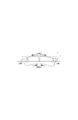
- FIG. 1 shows an ultrasonic peening method according to an embodiment of the present invention
- FIG. 1A shows a building construction process
- FIG. 1B shows a structure welding process
- FIG. 1C shows a building launch process
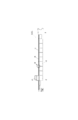
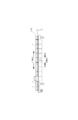
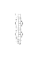
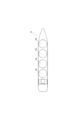
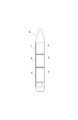
- 2A and 2B are diagrams showing a floating structure according to an embodiment of the present invention, in which FIG. 2A shows a side view of the container ship, and FIG. 2B shows a top view of the container ship.
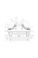
- FIG. 3 is an enlarged perspective view of a portion III in FIG. 4A and 4B are schematic diagrams for explaining the ultrasonic peening process.
- FIG. 1 shows an ultrasonic peening method according to an embodiment of the present invention
- FIG. 1A shows a building construction process
- FIG. 1B shows a structure welding process
- FIG. 1C shows a building launch process
- 2A and 2B are diagrams showing a floating structure according to an embodiment of the present invention,
- FIG. 4A is a perspective view of a welded portion before ultrasonic peening
- FIG. 4B is a perspective view of a welded portion during ultrasonic peening
- FIG. 4C is a perspective view of a welded portion after ultrasonic peening
- FIG. 4D is a cross-sectional view of a welded portion after ultrasonic peening
- FIG. 4E is a cross-sectional view of a welded portion subjected to a weld coating process after ultrasonic peening. Show.
- the ultrasonic peening method according to the embodiment of the present invention is applied to a welded portion 3 between a floating structure 1 and a structure 2 welded to the floating structure 1.
- An ultrasonic peening method for improving the fatigue strength of the welded portion 3 by applying an impact with a pin 4 vibrated by a sound wave, the building construction process for constructing the floating structure 1, and the floating structure 1 A structure welding process in which the structure 2 is welded to the structure, a building launch process in which the floating structure 1 to which the structure 2 is attached is launched, and a floating structure 1 in a state where buoyancy is generated
- the floating structure 1 is, for example, a ship having an opening on a deck, and specifically, a container ship 11 as shown in FIG. As shown in FIGS. 2A and 2B, the container ship 11 includes a plurality of holds 13 partitioned at a lower portion of the deck 12 of the hull, an opening 14 formed in the upper deck 12 of each hold 13, 14 and a hatch cover 15 covering 14. Further, the container ship 11 includes an engine room 16 and a bridge 17 on the rear side of the hull.
- the floating structure 1 is not limited to the container ship 11, but may be any other type of ship, marine plant, semi-sub-type, or floating as long as it is a floating structure that is built on land and launched. This includes a drilling rig of a type, a bottomed offshore structure that is temporarily launched during construction, and the like.
- the structure 2 is, for example, a fitting that is welded around the opening of a ship, and specifically, a fitting that is welded around the opening 14 of the container ship 11 as shown in FIG. It is a product.
- the container ship 11 has a hatch combing 21 erected on the deck 12 on the periphery of the opening 14.
- the hatch combing 21 includes a combing stay 23 disposed on the deck 12, a combing top 24 disposed on the combing stay 23, and a hatch end combing disposed on the edge of the opening 14 in the ship width direction. 25 and a hatch side combing 26 disposed at the edge of the opening 14 in the ship length direction.
- the combing stay 23 is welded and attached to the deck 12, the combing top 24 and the hatch side combing 26, and constitutes a beam material of the hatch combing 21 to increase its rigidity and strength.
- the combing top 24 is attached by welding to the combing stay 23, the hatch end combing 25 and the hatch side combing 26, and constitutes the upper part of the hatch combing 21.
- a plurality of rest pads 27 are attached to the combing top 24 by welding.
- the rest pad 27 is a component for fixing the hatch cover 15.
- the combing top 24 has a cross deck opening 28 so as to form a cross deck between the two openings 14.
- the hatch end combing 25 is welded to the deck 12, the combing top 24, and the hatch side combing 26, and constitutes a part of the wall surface surrounding the outer periphery of the opening 14.
- the hatch side combing 26 is welded and attached to the deck 12, the combing stay 23, the combing top 24, and the hatch end combing 25, and constitutes a part of the wall surface surrounding the outer periphery of the opening 14.
- the structure 2 described above is merely an example, and may be a part (for example, a handrail, a ladder, a winch rack, a ventilation pipe, a living area structure, or the like) welded to a place other than the periphery of the opening 14.
- it may be a part that is welded when the floating structure 1 is constructed, such as a building block that constitutes the hull, or a reinforcing material such as a bracket or small bone that is welded to the hull.
- the building construction process is a process of constructing the floating structure 1 on land.
- the floating structure 1 is a container ship 11, as shown in FIG. 1A, the container ship 11 is built on the stern 6 arranged in the dock 5.
- the structure welding process is a process of welding various structures 2 to the floating structure 1 on land.
- a structure 2 such as a hatch combing 21 or a hatch cover 15 is welded and attached to a container ship 11 built in the dock 5.
- a rust-preventing coating film can be formed on the welded part 3, and deterioration of the welded part 3 before the ultrasonic peening process can be suppressed.
- the structure welding process and the building construction process do not need to be clearly distinguished from each other.
- the structure welding is performed even when the hull structural member constituting the floating structure 1 is welded. It can be included in the process.
- the building launching step is a step of launching the floating structure 1 constructed on land and welded to the structure 2.
- a ship-type floating structure 1 such as a container ship 11
- an engine room 16 and a bridge 17 are often arranged on the stern side as shown in FIG. Therefore, as shown in FIG. 1C, the weight of the hull before and after the hull against buoyancy becomes heavier than the weight at the center of the hull, a vertical downward force is applied to the bow and stern, and a vertical upward force is applied to the hull center.
- a tensile force is generated on the deck 12 side and a compressive force is generated on the ship bottom side, and the floating structure 1 is in a so-called hogging state.
- a tensile force is also generated in the welded portion 3 of the structure 2 such as the hatch combing 21 welded on the deck 12.
- a large tensile force is likely to be generated at a grayed-out location.
- ultrasonic peening is applied to the welded part 3 before the building launching process, even if a compressive stress field is formed in the welded part 3 to improve fatigue strength, the welded part 3 as described above. As a result, tensile stress is applied to the film, and the effect of ultrasonic peening is diminished. Therefore, in the present invention, ultrasonic peening is performed after the floating structure 1 welded to the structure 2 is launched.
- the ultrasonic peening step is a step of performing ultrasonic peening on the welded portion 3 of the floating structure 1 in a state where buoyancy is generated by launching.
- an impact is applied to the welded part 3 by applying an impact to the welded part 3 of the floating structure 1 and the structure 2 with the pin 4 vibrated by ultrasonic waves.
- a ceramic piezoelectric element or a magnetostrictor may be used for exciting the pin 4.
- Such ultrasonic peening is particularly effective when applied to, for example, the corners of the structure 2 or the opening or the width direction portion of the welded portion 3 as shown in gray in FIG.
- a temporary coating peeling process for peeling the temporary coating coated in the welded part temporary coating process may be sandwiched before the ultrasonic peening process.
- Ultrasonic peening can be applied easily and effectively by peeling the anticorrosive coating film by this temporary coating peeling step.
- the coating film thickness does not affect the ultrasonic peening as in the case where the coating film thickness is thin or the coating film is soft, it is not always necessary to peel off the temporarily coated coating film.
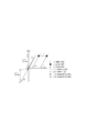
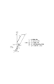
- FIG. 4A As a result of the structure welding process, as shown in FIG. 4A, two steel members 31 are welded, and a weld bead 32 is formed between them.
- the boundary between the steel member 31 and the weld bead 32 is referred to as a weld toe portion 33.
- FIG. 4B a pin 4 having a radius R at the tip is continuously hit against the weld toe 33 using ultrasonic waves as a vibration source.
- FIG. 4C this striking process is performed along the desired weld bead 32.
- an impact mark 34 is formed on the weld toe 33 by transferring the R shape of the pin 4 to the weld 3, and the shape of the weld toe 33 is improved.
- the residual compressive stress field 35 is formed.
- the welded portion 3 is pulled without any special dedicated jig or extra labor.
- Ultrasonic peening can be performed in a state where a stress field is acting, and reduction of the effect of ultrasonic peening due to launch can be suppressed.
- the floating structure 1 such as the container ship 11 having such an effect can be obtained.
- a welding part coating process for coating the welded part 3 may be sandwiched after the ultrasonic peening process.
- the rust preventive coating film 36 can be formed on the welded part 3 by such a welded part coating step, and deterioration of the welded part 3 can be suppressed.
- the welded part 3 is not temporarily coated, when the temporarily coated paint film of the welded part 3 is peeled off, when the ultrasonic peening is applied in the temporarily coated state and the paint film is peeled off, the welded part paint is applied. It is effective to carry out the process.
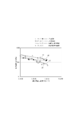
- FIG. 5 is a figure for demonstrating the effect by the ultrasonic peening construction method which concerns on embodiment of this invention, and has shown the test result of fatigue strength.
- the horizontal axis indicates the number of fracture repetitions Nf, and the vertical axis indicates the stress range ⁇ S.
- the test results shown in the figure show that since it is difficult to actually measure the fatigue strength of the welded part 3 using the floating structure 1 such as the container ship 11, two steel materials having a plate thickness of 16 mm (main plate and stiffener) The fatigue strength of the welded portion was measured using a test specimen welded with a metal.
- the UP treatment material means a treatment material that has been subjected to ultrasonic peening.
- Case (1) shows the relationship between the stress range ⁇ S generated in the welded part of the UP-treated material that has been subjected to ultrasonic peening under no load and the number of repetitions of fracture Nf. ing.
- Case (2) shows the relationship between the stress range ⁇ S generated in the welded portion of the UP untreated material where ultrasonic peening is not applied and the number of repetitions of fracture Nf, and is indicated by white diamonds and broken lines in the figure.
- Case (3) shows the relationship between the stress range ⁇ S generated in the welded portion with a tensile stress of 100 MPa applied to the UP-treated material that has been subjected to ultrasonic peening in an unloaded state, and the number of repetitions of fracture Nf.
- Case (4) shows the relationship between the stress range ⁇ S generated in the welded part of the UP-treated material subjected to ultrasonic peening under a tensile stress of 100 MPa and the number of repetitions of fracture Nf. is doing.
- the tensile stress of 100 MPa is substantially equal to the tensile stress applied to the welded portion 3 on the deck 12 when the container ship 11 is launched.
- case (4) has the highest fatigue strength, and the fatigue strength decreases in the order of case (1), case (3), and case (2). it can.
- case (3) even if ultrasonic peening is applied to the welded portion in an unloaded state and a compressive stress field is formed in the welded portion, the compressive stress field is reduced by applying a tensile stress of 100 MPa, It can be understood that the effect of improving fatigue strength by ultrasonic peening is reduced.
- case (3) the fatigue strength is almost the same as in case (2) where ultrasonic peening is not applied to the weld.
- a tensile stress field is formed by applying a tensile stress of 100 MPa to the weld, and ultrasonic peening is performed under the tensile stress field, and a compressive stress field is applied to the weld. Since it is formed, it is difficult to reduce the effect of improving the fatigue strength even when a tensile stress of 100 MPa is subsequently applied. Therefore, it can be understood that applying the ultrasonic peening to the welded portion 3 after launching the floating structure 1 such as the container ship 11 is effective in maintaining the effect of improving the fatigue strength.
- FIG. 6 is a correlation diagram showing the relationship between local stress and strain applied to the weld toe
- FIG. 6A shows the case where ultrasonic peening is applied without launching the floating structure and When sonic peening is not applied
- FIG. 6B shows a case where a floating structure is launched after ultrasonic peening is applied
- FIG. 6C shows a case where ultrasonic peening is applied after the floating structure is launched.
- the horizontal axis indicates strain
- the vertical axis indicates stress. When the stress is positive, tensile stress is generated. When the stress is negative, compressive stress is generated. If each figure is replaced with the case shown in FIG. 5, FIG. 6A corresponds to case (1) and case (2), FIG. 6B corresponds to case (3), and FIG. This corresponds to 4).
- the state in which the welding to the welded portion 3 is finished is referred to as (a) the welding finished state (open circle in the figure).
- the welding finished state open circle in the figure.
- the stress at the welded toe part 33 is Even if the tensile yield stress ⁇ Y is reached and the load is further increased, only the strain increases with the tensile yield stress ⁇ Y.
- This state is defined as (b) maximum stress state (black circle in the figure). As the load from the container ship 11 is unloaded, the stress at the weld toe 33 decreases due to elastic deformation, and the stress is minimized when all the load is unloaded.
- This state is referred to as (c) minimum stress state (circle with hatching in the figure).
- (c) minimum stress state (circle with hatching in the figure).
- the repeated nominal stress range acting on the welded portion 3 is ⁇ S
- Kt is a stress concentration factor
- the structure 2 in the floating structure 1 is welded to the predetermined structure 3 in the floating structure 1 by welding the structure 2 to the floating structure 1 and launching it, and then applying ultrasonic peening. It can be understood that ultrasonic peening can be performed in a state where a tensile stress field is formed, and the effect reduction due to the launch of ultrasonic peening can be suppressed.
- FIG. 7 is a figure which shows the modification of the ultrasonic peening construction method based on this invention
- FIG. 7A has shown the 1st modification
- FIG. 7B has shown the 2nd modification.
- a container ship 11 is adopted as the floating structure 1.
- ultrasonic peening is performed in a state where a load 7 (for example, a container) is loaded on the floating structure 1 (container ship 11). It is what I did.
- a load 7 for example, a container
- the maximum buoyancy can be generated in the container ship 11, and the tensile stress can be effectively generated in the welded portion 3.
- ultrasonic peening may be performed in a state where only some of the loads 7 are stacked.
- the buoyancy generated in the floating structure 1 is adjusted by adjusting the loading position and loading weight of the load 7 in the ultrasonic peening process described above. It is a thing.
- the load 7 is loaded at three locations, the bow, the hull center and the stern, so as to generate the optimum tensile stress on the deck 12 between the bow and the hull center and between the hull center and the stern. ing.
- the load 7 may be loaded on the bow and stern to generate an optimum tensile stress on the deck 12 at the center of the hull.
- the load 7 is not limited to a container, and may be fuel or ballast water.
- FIG. 8 is a view showing a floating structure according to another embodiment of the present invention
- FIG. 8A is a top view of a moss type LNG ship
- FIG. 8B is a top view of a multipurpose cargo ship. Yes.
- the moss type LNG ship 18 shown in FIG. 8A includes a plurality of spherical tanks 18a. Accordingly, an opening for mounting the spherical tank 18a is formed in the hull of the moss type LNG ship 18. Even in the case of the moth type LNG ship 18, the fatigue strength can be effectively improved by applying ultrasonic peening after the launch.
- the bulk carrier, the VLCC tanker, and the like have substantially the same form as the container ship 11 and the multipurpose cargo ship 19.
- a ship having an opening in the hull has been described.
- the present invention is not limited to such a ship, and is a floating structure built on land or in a place where buoyancy does not occur. As long as a predetermined structure is welded to the hull such as the deck, the ship may not have an opening.
Landscapes
- Engineering & Computer Science (AREA)
- Mechanical Engineering (AREA)
- Chemical & Material Sciences (AREA)
- Physics & Mathematics (AREA)
- Organic Chemistry (AREA)
- Crystallography & Structural Chemistry (AREA)
- Materials Engineering (AREA)
- Metallurgy (AREA)
- Optics & Photonics (AREA)
- Architecture (AREA)
- Structural Engineering (AREA)
- Combustion & Propulsion (AREA)
- Ocean & Marine Engineering (AREA)
- Thermal Sciences (AREA)
- Butt Welding And Welding Of Specific Article (AREA)
Abstract
Description
2 構造物
3 溶接部
4 ピン
5 ドック
6 船台
7 積載物
11 コンテナ船
12 甲板
13 船倉
14 開口部
15 ハッチカバー
16 エンジンルーム
17 船橋
18 モス型LNG船
18a 球形タンク
19 多目的貨物船
19a 開口部
19b ハッチカバー
21 ハッチコーミング
23 コーミングステイ
24 コーミングトップ
25 ハッチエンドコーミング
26 ハッチサイドコーミング
27 レストパッド
28 クロスデッキ用開口部
31 鋼部材
32 溶接ビード
33 溶接止端部
34 打撃痕
35 残留圧縮応力場
36 防錆塗膜
Claims (9)
- 浮体式建造物と該浮体式建造物に溶接される構造物との溶接部に超音波により加振されたピンで衝撃を与えて前記溶接部の疲労強度を向上させる超音波ピーニング施工方法であって、
前記浮体式建造物に前記構造物を溶接して取り付ける構造物溶接工程と、
前記構造物を取り付けた前記浮体式建造物を進水させる建造物進水工程と、
浮力が生じている状態の前記浮体式建造物の前記溶接部に対して超音波ピーニングを施工する超音波ピーニング工程と、を有することを特徴とする。 - 請求項1に記載の超音波ピーニング施工方法であって、
前記超音波ピーニング工程は、前記浮体式建造物に積載物を積み付けた状態で施工されることを特徴とする。 - 請求項2に記載の超音波ピーニング施工方法であって、
前記積載物の積載位置及び積載重量を調整して前記浮体式建造物に生じる浮力を調整することを特徴とする。 - 請求項2に記載の超音波ピーニング施工方法であって、
前記構造物溶接工程の後に、前記溶接部を被覆する仮塗装を行う溶接部仮塗装工程を有することを特徴とする。 - 請求項4に記載の超音波ピーニング施工方法であって、
前記超音波ピーニング工程の前に、前記仮塗装を剥離する仮塗装剥離工程を有することを特徴とする。 - 請求項1に記載の超音波ピーニング施工方法であって、
前記超音波ピーニング工程の後に、前記溶接部を被覆する塗装を行う溶接部塗装工程を有することを特徴とする。 - 請求項1に記載の超音波ピーニング施工方法であって、
前記浮体式建造物は、甲板に開口部を有する船舶であることを特徴とする。 - 請求項7に記載の超音波ピーニング施工方法であって、
前記構造物は、前記開口部の周辺に溶接される艤装品であることを特徴とする。 - 溶接によって取り付けられる構造物を有する浮体式建造物であって、
該浮体式建造物と前記構造物との溶接部には、請求項1乃至8の何れかに記載の超音波ピーニング施工方法により超音波ピーニングが施工されていることを特徴とする。
Priority Applications (2)
| Application Number | Priority Date | Filing Date | Title |
|---|---|---|---|
| CN201180019073.XA CN102844147B (zh) | 2010-04-14 | 2011-04-14 | 超声波喷丸施工方法及浮体式建造物 |
| KR1020127026347A KR20130056219A (ko) | 2010-04-14 | 2011-04-14 | 초음파 피닝 시공 방법 및 부유식 건조물 |
Applications Claiming Priority (2)
| Application Number | Priority Date | Filing Date | Title |
|---|---|---|---|
| JP2010-093231 | 2010-04-14 | ||
| JP2010093231A JP5543261B2 (ja) | 2010-04-14 | 2010-04-14 | 超音波ピーニング施工方法 |
Publications (1)
| Publication Number | Publication Date |
|---|---|
| WO2011129401A1 true WO2011129401A1 (ja) | 2011-10-20 |
Family
ID=44798770
Family Applications (1)
| Application Number | Title | Priority Date | Filing Date |
|---|---|---|---|
| PCT/JP2011/059280 Ceased WO2011129401A1 (ja) | 2010-04-14 | 2011-04-14 | 超音波ピーニング施工方法及び浮体式建造物 |
Country Status (4)
| Country | Link |
|---|---|
| JP (1) | JP5543261B2 (ja) |
| KR (1) | KR20130056219A (ja) |
| CN (1) | CN102844147B (ja) |
| WO (1) | WO2011129401A1 (ja) |
Families Citing this family (3)
| Publication number | Priority date | Publication date | Assignee | Title |
|---|---|---|---|---|
| KR20200052574A (ko) | 2018-11-07 | 2020-05-15 | 대우조선해양 주식회사 | 면상 임팩트 방식의 초음파 피닝장치 |
| JP7201096B2 (ja) * | 2020-03-26 | 2023-01-10 | 日本製鉄株式会社 | ピーニング処理装置、ピーニング処理方法および構造物の製造方法 |
| JP7834174B2 (ja) * | 2022-07-14 | 2026-03-23 | 川崎重工業株式会社 | 液化ガス運搬船の運用方法及び液化ガス運搬船 |
Citations (5)
| Publication number | Priority date | Publication date | Assignee | Title |
|---|---|---|---|---|
| JPH07328855A (ja) * | 1994-06-09 | 1995-12-19 | Babcock Hitachi Kk | ウォータージェットピーニング法 |
| JP2006051540A (ja) * | 2004-07-14 | 2006-02-23 | Nippon Steel Corp | 衝撃塑性加工方法 |
| JP2008290125A (ja) * | 2007-05-25 | 2008-12-04 | Nippon Steel Corp | 疲労耐久性に優れた船舶および船舶の疲労耐久性向上方法 |
| JP2009034721A (ja) * | 2007-08-03 | 2009-02-19 | Nippon Steel Corp | 耐疲労特性に優れた溶接継手の製作方法およびその製作装置 |
| WO2010013658A1 (ja) * | 2008-07-28 | 2010-02-04 | 新日本製鐵株式会社 | 溶接継手の疲労特性改善打撃処理方法及びその疲労特性改善打撃処理装置並びに耐疲労特性に優れた溶接構造物 |
Family Cites Families (6)
| Publication number | Priority date | Publication date | Assignee | Title |
|---|---|---|---|---|
| JP3899007B2 (ja) * | 2002-10-08 | 2007-03-28 | 新日本製鐵株式会社 | 重ね隅肉溶接継手の疲労強度向上方法 |
| JP4189201B2 (ja) * | 2002-10-30 | 2008-12-03 | 新日本製鐵株式会社 | 鋼材の溶接継手における熱影響部の靭性向上方法 |
| JP2006055899A (ja) * | 2004-08-23 | 2006-03-02 | Nippon Steel Corp | 溶接継手の疲労寿命改善方法 |
| JP2006175512A (ja) * | 2004-12-24 | 2006-07-06 | Nippon Steel Corp | 溶接部の疲労強度向上方法およびそれを用いた溶接構造物 |
| CN1324160C (zh) * | 2005-04-07 | 2007-07-04 | 天津大学 | 改善焊接结构疲劳性能的等离子喷涂法 |
| JP5130478B2 (ja) * | 2007-07-31 | 2013-01-30 | 新日鐵住金株式会社 | 疲労特性に優れた突合せ溶接継手およびその製造方法 |
-
2010
- 2010-04-14 JP JP2010093231A patent/JP5543261B2/ja active Active
-
2011
- 2011-04-14 CN CN201180019073.XA patent/CN102844147B/zh active Active
- 2011-04-14 WO PCT/JP2011/059280 patent/WO2011129401A1/ja not_active Ceased
- 2011-04-14 KR KR1020127026347A patent/KR20130056219A/ko not_active Ceased
Patent Citations (5)
| Publication number | Priority date | Publication date | Assignee | Title |
|---|---|---|---|---|
| JPH07328855A (ja) * | 1994-06-09 | 1995-12-19 | Babcock Hitachi Kk | ウォータージェットピーニング法 |
| JP2006051540A (ja) * | 2004-07-14 | 2006-02-23 | Nippon Steel Corp | 衝撃塑性加工方法 |
| JP2008290125A (ja) * | 2007-05-25 | 2008-12-04 | Nippon Steel Corp | 疲労耐久性に優れた船舶および船舶の疲労耐久性向上方法 |
| JP2009034721A (ja) * | 2007-08-03 | 2009-02-19 | Nippon Steel Corp | 耐疲労特性に優れた溶接継手の製作方法およびその製作装置 |
| WO2010013658A1 (ja) * | 2008-07-28 | 2010-02-04 | 新日本製鐵株式会社 | 溶接継手の疲労特性改善打撃処理方法及びその疲労特性改善打撃処理装置並びに耐疲労特性に優れた溶接構造物 |
Also Published As
| Publication number | Publication date |
|---|---|
| JP5543261B2 (ja) | 2014-07-09 |
| KR20130056219A (ko) | 2013-05-29 |
| CN102844147A (zh) | 2012-12-26 |
| JP2011218438A (ja) | 2011-11-04 |
| CN102844147B (zh) | 2015-05-06 |
Similar Documents
| Publication | Publication Date | Title |
|---|---|---|
| US9494131B2 (en) | Monopile foundation for offshore wind turbine | |
| Golumbfskie et al. | Survey of detection, mitigation, and repair technologies to address problems caused by sensitization of Al-Mg alloys on navy ships | |
| CN102292258B (zh) | 用于在双体船系统的干舷和格排上减少负载及节省钢材的预加载 | |
| JP5543261B2 (ja) | 超音波ピーニング施工方法 | |
| Wang et al. | Latest progress in floatover technologies for offshore installations and decommissioning | |
| KR100914350B1 (ko) | 반잠수 상태의 부력을 이용한 도크 단계에서의 탱크하이드로 테스트 방법 | |
| JP2006507984A (ja) | 船舶構造および船舶の構造 | |
| JP4949598B2 (ja) | 既存の金属構造体の補強方法、パイプ補強方法、パイプラインに対するスプールラインの付設方法 | |
| Kortenoeven et al. | Application of sandwich panels in design and building of dredging ships | |
| KR101566522B1 (ko) | 대형 블록 탑재 방법 | |
| KR20130040389A (ko) | 선박 건조용 반목배치 방법 | |
| JP2008290125A (ja) | 疲労耐久性に優れた船舶および船舶の疲労耐久性向上方法 | |
| CN106347583B (zh) | 可拆卸式靠泊工装 | |
| KR101078434B1 (ko) | 부양식 도크를 이용한 2척 선박 건조 방법 | |
| KR200468323Y1 (ko) | 선박 계류용 펜더 | |
| KR101566524B1 (ko) | 대형 블록 탑재 방법 | |
| JP7006467B2 (ja) | 溶接継手 | |
| KR20140141320A (ko) | 해상 구조물 건조 공법 | |
| KR20130109656A (ko) | 선박의 진수방법 | |
| Zhang1a et al. | A new block assembly method for shipbuilding at sea | |
| Ariesta et al. | A CRITICAL REVIEW ON FATIGUE ASSESSMENT APPROACH IN SHIP STRUCTURAL DETAILS | |
| Yucel et al. | Analysis of free and forced ship vibrations using finite element method | |
| Petershagen | Fatigue Assessment of Welded Ship Structures | |
| Cai et al. | Research on Simplified Fatigue Assessment for Longitudinals of Large Container Ship Considering Warping | |
| JP2009113734A (ja) | シングルハル貨物船のダブルハル化工法 |
Legal Events
| Date | Code | Title | Description |
|---|---|---|---|
| WWE | Wipo information: entry into national phase |
Ref document number: 201180019073.X Country of ref document: CN |
|
| 121 | Ep: the epo has been informed by wipo that ep was designated in this application |
Ref document number: 11768922 Country of ref document: EP Kind code of ref document: A1 |
|
| ENP | Entry into the national phase |
Ref document number: 20127026347 Country of ref document: KR Kind code of ref document: A |
|
| NENP | Non-entry into the national phase |
Ref country code: DE |
|
| 122 | Ep: pct application non-entry in european phase |
Ref document number: 11768922 Country of ref document: EP Kind code of ref document: A1 |