WO2011125771A1 - ハニカムフィルタ及びハニカムフィルタの製造方法 - Google Patents
ハニカムフィルタ及びハニカムフィルタの製造方法 Download PDFInfo
- Publication number
- WO2011125771A1 WO2011125771A1 PCT/JP2011/058081 JP2011058081W WO2011125771A1 WO 2011125771 A1 WO2011125771 A1 WO 2011125771A1 JP 2011058081 W JP2011058081 W JP 2011058081W WO 2011125771 A1 WO2011125771 A1 WO 2011125771A1
- Authority
- WO
- WIPO (PCT)
- Prior art keywords
- catalyst
- collection layer
- partition wall
- honeycomb filter
- layer
- Prior art date
Links
- 238000000034 method Methods 0.000 title claims abstract description 89
- 238000004519 manufacturing process Methods 0.000 title claims description 25
- 239000003054 catalyst Substances 0.000 claims abstract description 407
- 238000005192 partition Methods 0.000 claims abstract description 185
- 238000011144 upstream manufacturing Methods 0.000 claims abstract description 114
- 239000007787 solid Substances 0.000 claims abstract description 20
- 210000004027 cell Anatomy 0.000 claims description 71
- 239000012530 fluid Substances 0.000 claims description 39
- 239000010410 layer Substances 0.000 description 257
- 241000264877 Hippospongia communis Species 0.000 description 221
- 239000002245 particle Substances 0.000 description 83
- 239000013618 particulate matter Substances 0.000 description 58
- 230000008569 process Effects 0.000 description 52
- 239000007789 gas Substances 0.000 description 43
- 238000000746 purification Methods 0.000 description 35
- 239000002002 slurry Substances 0.000 description 32
- 230000015572 biosynthetic process Effects 0.000 description 31
- 239000011148 porous material Substances 0.000 description 30
- 230000000052 comparative effect Effects 0.000 description 26
- 238000005259 measurement Methods 0.000 description 26
- VYPSYNLAJGMNEJ-UHFFFAOYSA-N Silicium dioxide Chemical compound O=[Si]=O VYPSYNLAJGMNEJ-UHFFFAOYSA-N 0.000 description 23
- HBMJWWWQQXIZIP-UHFFFAOYSA-N silicon carbide Chemical compound [Si+]#[C-] HBMJWWWQQXIZIP-UHFFFAOYSA-N 0.000 description 22
- 229910010271 silicon carbide Inorganic materials 0.000 description 22
- 229910003465 moissanite Inorganic materials 0.000 description 21
- 230000008929 regeneration Effects 0.000 description 21
- 238000011069 regeneration method Methods 0.000 description 21
- 239000000463 material Substances 0.000 description 19
- 239000002994 raw material Substances 0.000 description 19
- 239000011230 binding agent Substances 0.000 description 18
- 238000010438 heat treatment Methods 0.000 description 17
- 239000010954 inorganic particle Substances 0.000 description 17
- PNEYBMLMFCGWSK-UHFFFAOYSA-N aluminium oxide Inorganic materials [O-2].[O-2].[O-2].[Al+3].[Al+3] PNEYBMLMFCGWSK-UHFFFAOYSA-N 0.000 description 15
- 238000001035 drying Methods 0.000 description 14
- 239000004215 Carbon black (E152) Substances 0.000 description 12
- 238000010586 diagram Methods 0.000 description 12
- 229930195733 hydrocarbon Natural products 0.000 description 12
- 150000002430 hydrocarbons Chemical class 0.000 description 12
- 238000007254 oxidation reaction Methods 0.000 description 12
- 238000000921 elemental analysis Methods 0.000 description 11
- 229910010272 inorganic material Inorganic materials 0.000 description 11
- 239000011147 inorganic material Substances 0.000 description 11
- 230000003647 oxidation Effects 0.000 description 11
- MCMNRKCIXSYSNV-UHFFFAOYSA-N Zirconium dioxide Chemical compound O=[Zr]=O MCMNRKCIXSYSNV-UHFFFAOYSA-N 0.000 description 10
- 239000012784 inorganic fiber Substances 0.000 description 10
- BASFCYQUMIYNBI-UHFFFAOYSA-N platinum Chemical compound [Pt] BASFCYQUMIYNBI-UHFFFAOYSA-N 0.000 description 10
- 239000000523 sample Substances 0.000 description 9
- 239000000377 silicon dioxide Substances 0.000 description 9
- 239000000243 solution Substances 0.000 description 9
- XLYOFNOQVPJJNP-UHFFFAOYSA-N water Substances O XLYOFNOQVPJJNP-UHFFFAOYSA-N 0.000 description 9
- GWEVSGVZZGPLCZ-UHFFFAOYSA-N Titan oxide Chemical compound O=[Ti]=O GWEVSGVZZGPLCZ-UHFFFAOYSA-N 0.000 description 8
- 229910052878 cordierite Inorganic materials 0.000 description 8
- JSKIRARMQDRGJZ-UHFFFAOYSA-N dimagnesium dioxido-bis[(1-oxido-3-oxo-2,4,6,8,9-pentaoxa-1,3-disila-5,7-dialuminabicyclo[3.3.1]nonan-7-yl)oxy]silane Chemical compound [Mg++].[Mg++].[O-][Si]([O-])(O[Al]1O[Al]2O[Si](=O)O[Si]([O-])(O1)O2)O[Al]1O[Al]2O[Si](=O)O[Si]([O-])(O1)O2 JSKIRARMQDRGJZ-UHFFFAOYSA-N 0.000 description 8
- 239000002612 dispersion medium Substances 0.000 description 8
- 238000009826 distribution Methods 0.000 description 8
- 238000010304 firing Methods 0.000 description 8
- 239000004927 clay Substances 0.000 description 7
- 230000000694 effects Effects 0.000 description 7
- 229910000510 noble metal Inorganic materials 0.000 description 7
- 229920005989 resin Polymers 0.000 description 7
- 239000011347 resin Substances 0.000 description 7
- LYCAIKOWRPUZTN-UHFFFAOYSA-N Ethylene glycol Chemical compound OCCO LYCAIKOWRPUZTN-UHFFFAOYSA-N 0.000 description 6
- KDLHZDBZIXYQEI-UHFFFAOYSA-N Palladium Chemical compound [Pd] KDLHZDBZIXYQEI-UHFFFAOYSA-N 0.000 description 6
- 238000002485 combustion reaction Methods 0.000 description 6
- -1 sialon Chemical compound 0.000 description 6
- 229910000505 Al2TiO5 Inorganic materials 0.000 description 5
- 239000008119 colloidal silica Substances 0.000 description 5
- 230000008021 deposition Effects 0.000 description 5
- KZHJGOXRZJKJNY-UHFFFAOYSA-N dioxosilane;oxo(oxoalumanyloxy)alumane Chemical compound O=[Si]=O.O=[Si]=O.O=[Al]O[Al]=O.O=[Al]O[Al]=O.O=[Al]O[Al]=O KZHJGOXRZJKJNY-UHFFFAOYSA-N 0.000 description 5
- 229910052863 mullite Inorganic materials 0.000 description 5
- AABBHSMFGKYLKE-SNAWJCMRSA-N propan-2-yl (e)-but-2-enoate Chemical compound C\C=C\C(=O)OC(C)C AABBHSMFGKYLKE-SNAWJCMRSA-N 0.000 description 5
- 239000000758 substrate Substances 0.000 description 5
- 229910052581 Si3N4 Inorganic materials 0.000 description 4
- 239000002585 base Substances 0.000 description 4
- 238000001354 calcination Methods 0.000 description 4
- 229910052751 metal Inorganic materials 0.000 description 4
- 239000002184 metal Substances 0.000 description 4
- 229910052697 platinum Inorganic materials 0.000 description 4
- HQVNEWCFYHHQES-UHFFFAOYSA-N silicon nitride Chemical compound N12[Si]34N5[Si]62N3[Si]51N64 HQVNEWCFYHHQES-UHFFFAOYSA-N 0.000 description 4
- 229910052717 sulfur Inorganic materials 0.000 description 4
- 229910052723 transition metal Inorganic materials 0.000 description 4
- 229910000166 zirconium phosphate Inorganic materials 0.000 description 4
- LEHFSLREWWMLPU-UHFFFAOYSA-B zirconium(4+);tetraphosphate Chemical compound [Zr+4].[Zr+4].[Zr+4].[O-]P([O-])([O-])=O.[O-]P([O-])([O-])=O.[O-]P([O-])([O-])=O.[O-]P([O-])([O-])=O LEHFSLREWWMLPU-UHFFFAOYSA-B 0.000 description 4
- 239000012298 atmosphere Substances 0.000 description 3
- 230000008859 change Effects 0.000 description 3
- 239000002270 dispersing agent Substances 0.000 description 3
- 238000011049 filling Methods 0.000 description 3
- 238000002156 mixing Methods 0.000 description 3
- 229910052763 palladium Inorganic materials 0.000 description 3
- 231100000572 poisoning Toxicity 0.000 description 3
- 230000000607 poisoning effect Effects 0.000 description 3
- 238000005498 polishing Methods 0.000 description 3
- 239000000843 powder Substances 0.000 description 3
- 239000010970 precious metal Substances 0.000 description 3
- 239000011863 silicon-based powder Substances 0.000 description 3
- 239000002344 surface layer Substances 0.000 description 3
- 239000004094 surface-active agent Substances 0.000 description 3
- 150000003624 transition metals Chemical class 0.000 description 3
- 230000000007 visual effect Effects 0.000 description 3
- NINIDFKCEFEMDL-UHFFFAOYSA-N Sulfur Chemical compound [S] NINIDFKCEFEMDL-UHFFFAOYSA-N 0.000 description 2
- 229910052784 alkaline earth metal Inorganic materials 0.000 description 2
- 150000001342 alkaline earth metals Chemical class 0.000 description 2
- 229910052788 barium Inorganic materials 0.000 description 2
- 229910052791 calcium Inorganic materials 0.000 description 2
- 239000001913 cellulose Substances 0.000 description 2
- 229920002678 cellulose Polymers 0.000 description 2
- 239000000919 ceramic Substances 0.000 description 2
- 239000013025 ceria-based material Substances 0.000 description 2
- 239000011248 coating agent Substances 0.000 description 2
- 238000000576 coating method Methods 0.000 description 2
- 238000010276 construction Methods 0.000 description 2
- HNPSIPDUKPIQMN-UHFFFAOYSA-N dioxosilane;oxo(oxoalumanyloxy)alumane Chemical compound O=[Si]=O.O=[Al]O[Al]=O HNPSIPDUKPIQMN-UHFFFAOYSA-N 0.000 description 2
- 238000007598 dipping method Methods 0.000 description 2
- 239000000835 fiber Substances 0.000 description 2
- 239000010931 gold Substances 0.000 description 2
- 238000004898 kneading Methods 0.000 description 2
- 229920000609 methyl cellulose Polymers 0.000 description 2
- 239000001923 methylcellulose Substances 0.000 description 2
- 235000010981 methylcellulose Nutrition 0.000 description 2
- 230000002093 peripheral effect Effects 0.000 description 2
- 239000004033 plastic Substances 0.000 description 2
- 229920003023 plastic Polymers 0.000 description 2
- 229910052761 rare earth metal Inorganic materials 0.000 description 2
- 150000002910 rare earth metals Chemical class 0.000 description 2
- 239000010948 rhodium Substances 0.000 description 2
- 239000003566 sealing material Substances 0.000 description 2
- 239000002904 solvent Substances 0.000 description 2
- 229910052712 strontium Inorganic materials 0.000 description 2
- 239000011593 sulfur Substances 0.000 description 2
- 229920002134 Carboxymethyl cellulose Polymers 0.000 description 1
- 229910052684 Cerium Inorganic materials 0.000 description 1
- 229910052688 Gadolinium Inorganic materials 0.000 description 1
- 229910052779 Neodymium Inorganic materials 0.000 description 1
- BPQQTUXANYXVAA-UHFFFAOYSA-N Orthosilicate Chemical compound [O-][Si]([O-])([O-])[O-] BPQQTUXANYXVAA-UHFFFAOYSA-N 0.000 description 1
- 239000004372 Polyvinyl alcohol Substances 0.000 description 1
- 229910052777 Praseodymium Inorganic materials 0.000 description 1
- 229910052772 Samarium Inorganic materials 0.000 description 1
- BQCADISMDOOEFD-UHFFFAOYSA-N Silver Chemical compound [Ag] BQCADISMDOOEFD-UHFFFAOYSA-N 0.000 description 1
- 229920002472 Starch Polymers 0.000 description 1
- 229910021536 Zeolite Inorganic materials 0.000 description 1
- 239000003463 adsorbent Substances 0.000 description 1
- 229910052783 alkali metal Inorganic materials 0.000 description 1
- 150000001340 alkali metals Chemical class 0.000 description 1
- 229910052782 aluminium Inorganic materials 0.000 description 1
- XAGFODPZIPBFFR-UHFFFAOYSA-N aluminium Chemical compound [Al] XAGFODPZIPBFFR-UHFFFAOYSA-N 0.000 description 1
- 229910000323 aluminium silicate Inorganic materials 0.000 description 1
- 229910052792 caesium Inorganic materials 0.000 description 1
- 238000004364 calculation method Methods 0.000 description 1
- 239000001768 carboxy methyl cellulose Substances 0.000 description 1
- 235000010948 carboxy methyl cellulose Nutrition 0.000 description 1
- 239000008112 carboxymethyl-cellulose Substances 0.000 description 1
- 230000003197 catalytic effect Effects 0.000 description 1
- CETPSERCERDGAM-UHFFFAOYSA-N ceric oxide Chemical compound O=[Ce]=O CETPSERCERDGAM-UHFFFAOYSA-N 0.000 description 1
- GWXLDORMOJMVQZ-UHFFFAOYSA-N cerium Chemical compound [Ce] GWXLDORMOJMVQZ-UHFFFAOYSA-N 0.000 description 1
- 229910000422 cerium(IV) oxide Inorganic materials 0.000 description 1
- 239000003795 chemical substances by application Substances 0.000 description 1
- 229910052804 chromium Inorganic materials 0.000 description 1
- 239000000571 coke Substances 0.000 description 1
- 239000000567 combustion gas Substances 0.000 description 1
- 239000000470 constituent Substances 0.000 description 1
- 229910052802 copper Inorganic materials 0.000 description 1
- 238000005520 cutting process Methods 0.000 description 1
- 230000007423 decrease Effects 0.000 description 1
- 230000006866 deterioration Effects 0.000 description 1
- 238000010828 elution Methods 0.000 description 1
- 238000005516 engineering process Methods 0.000 description 1
- 239000003822 epoxy resin Substances 0.000 description 1
- 238000001125 extrusion Methods 0.000 description 1
- 238000001914 filtration Methods 0.000 description 1
- 239000010419 fine particle Substances 0.000 description 1
- 238000007667 floating Methods 0.000 description 1
- 239000000446 fuel Substances 0.000 description 1
- PCHJSUWPFVWCPO-UHFFFAOYSA-N gold Chemical compound [Au] PCHJSUWPFVWCPO-UHFFFAOYSA-N 0.000 description 1
- 229910052737 gold Inorganic materials 0.000 description 1
- 238000010191 image analysis Methods 0.000 description 1
- 238000002347 injection Methods 0.000 description 1
- 239000007924 injection Substances 0.000 description 1
- 229910052809 inorganic oxide Inorganic materials 0.000 description 1
- 229910052742 iron Inorganic materials 0.000 description 1
- 229910052746 lanthanum Inorganic materials 0.000 description 1
- 229910052744 lithium Inorganic materials 0.000 description 1
- 238000011068 loading method Methods 0.000 description 1
- 229910052749 magnesium Inorganic materials 0.000 description 1
- 229910052748 manganese Inorganic materials 0.000 description 1
- 230000000873 masking effect Effects 0.000 description 1
- QSHDDOUJBYECFT-UHFFFAOYSA-N mercury Chemical compound [Hg] QSHDDOUJBYECFT-UHFFFAOYSA-N 0.000 description 1
- 229910052753 mercury Inorganic materials 0.000 description 1
- 239000000203 mixture Substances 0.000 description 1
- 238000000465 moulding Methods 0.000 description 1
- 229910052759 nickel Inorganic materials 0.000 description 1
- 230000001590 oxidative effect Effects 0.000 description 1
- 230000035699 permeability Effects 0.000 description 1
- 229920000647 polyepoxide Polymers 0.000 description 1
- 229920002451 polyvinyl alcohol Polymers 0.000 description 1
- 229910052700 potassium Inorganic materials 0.000 description 1
- 238000010248 power generation Methods 0.000 description 1
- 238000002360 preparation method Methods 0.000 description 1
- 230000009467 reduction Effects 0.000 description 1
- 229910052703 rhodium Inorganic materials 0.000 description 1
- MHOVAHRLVXNVSD-UHFFFAOYSA-N rhodium atom Chemical compound [Rh] MHOVAHRLVXNVSD-UHFFFAOYSA-N 0.000 description 1
- 230000000630 rising effect Effects 0.000 description 1
- 229910052706 scandium Inorganic materials 0.000 description 1
- VSZWPYCFIRKVQL-UHFFFAOYSA-N selanylidenegallium;selenium Chemical compound [Se].[Se]=[Ga].[Se]=[Ga] VSZWPYCFIRKVQL-UHFFFAOYSA-N 0.000 description 1
- 238000000926 separation method Methods 0.000 description 1
- XJKVPKYVPCWHFO-UHFFFAOYSA-N silicon;hydrate Chemical compound O.[Si] XJKVPKYVPCWHFO-UHFFFAOYSA-N 0.000 description 1
- 229910052709 silver Inorganic materials 0.000 description 1
- 239000004332 silver Substances 0.000 description 1
- 238000005245 sintering Methods 0.000 description 1
- 229910052708 sodium Inorganic materials 0.000 description 1
- 239000008107 starch Substances 0.000 description 1
- 235000019698 starch Nutrition 0.000 description 1
- 239000007858 starting material Substances 0.000 description 1
- 238000003860 storage Methods 0.000 description 1
- 239000000126 substance Substances 0.000 description 1
- 230000002195 synergetic effect Effects 0.000 description 1
- 239000013076 target substance Substances 0.000 description 1
- 230000008646 thermal stress Effects 0.000 description 1
- 229910052719 titanium Inorganic materials 0.000 description 1
- 239000006163 transport media Substances 0.000 description 1
- 229910052720 vanadium Inorganic materials 0.000 description 1
- 239000002699 waste material Substances 0.000 description 1
- 229910052727 yttrium Inorganic materials 0.000 description 1
- 239000010457 zeolite Substances 0.000 description 1
- 229910052725 zinc Inorganic materials 0.000 description 1
Images


Classifications
-
- B—PERFORMING OPERATIONS; TRANSPORTING
- B01—PHYSICAL OR CHEMICAL PROCESSES OR APPARATUS IN GENERAL
- B01J—CHEMICAL OR PHYSICAL PROCESSES, e.g. CATALYSIS OR COLLOID CHEMISTRY; THEIR RELEVANT APPARATUS
- B01J37/00—Processes, in general, for preparing catalysts; Processes, in general, for activation of catalysts
- B01J37/02—Impregnation, coating or precipitation
- B01J37/0215—Coating
-
- B—PERFORMING OPERATIONS; TRANSPORTING
- B01—PHYSICAL OR CHEMICAL PROCESSES OR APPARATUS IN GENERAL
- B01D—SEPARATION
- B01D53/00—Separation of gases or vapours; Recovering vapours of volatile solvents from gases; Chemical or biological purification of waste gases, e.g. engine exhaust gases, smoke, fumes, flue gases, aerosols
- B01D53/34—Chemical or biological purification of waste gases
- B01D53/92—Chemical or biological purification of waste gases of engine exhaust gases
- B01D53/94—Chemical or biological purification of waste gases of engine exhaust gases by catalytic processes
- B01D53/944—Simultaneously removing carbon monoxide, hydrocarbons or carbon making use of oxidation catalysts
-
- B—PERFORMING OPERATIONS; TRANSPORTING
- B01—PHYSICAL OR CHEMICAL PROCESSES OR APPARATUS IN GENERAL
- B01J—CHEMICAL OR PHYSICAL PROCESSES, e.g. CATALYSIS OR COLLOID CHEMISTRY; THEIR RELEVANT APPARATUS
- B01J23/00—Catalysts comprising metals or metal oxides or hydroxides, not provided for in group B01J21/00
- B01J23/38—Catalysts comprising metals or metal oxides or hydroxides, not provided for in group B01J21/00 of noble metals
- B01J23/54—Catalysts comprising metals or metal oxides or hydroxides, not provided for in group B01J21/00 of noble metals combined with metals, oxides or hydroxides provided for in groups B01J23/02 - B01J23/36
- B01J23/56—Platinum group metals
- B01J23/64—Platinum group metals with arsenic, antimony, bismuth, vanadium, niobium, tantalum, polonium, chromium, molybdenum, tungsten, manganese, technetium or rhenium
- B01J23/656—Manganese, technetium or rhenium
- B01J23/6562—Manganese
-
- B01J35/40—
-
- B—PERFORMING OPERATIONS; TRANSPORTING
- B01—PHYSICAL OR CHEMICAL PROCESSES OR APPARATUS IN GENERAL
- B01D—SEPARATION
- B01D2255/00—Catalysts
- B01D2255/10—Noble metals or compounds thereof
- B01D2255/102—Platinum group metals
- B01D2255/1021—Platinum
-
- B—PERFORMING OPERATIONS; TRANSPORTING
- B01—PHYSICAL OR CHEMICAL PROCESSES OR APPARATUS IN GENERAL
- B01D—SEPARATION
- B01D2255/00—Catalysts
- B01D2255/20—Metals or compounds thereof
- B01D2255/206—Rare earth metals
- B01D2255/2061—Yttrium
-
- B—PERFORMING OPERATIONS; TRANSPORTING
- B01—PHYSICAL OR CHEMICAL PROCESSES OR APPARATUS IN GENERAL
- B01D—SEPARATION
- B01D2255/00—Catalysts
- B01D2255/20—Metals or compounds thereof
- B01D2255/206—Rare earth metals
- B01D2255/2065—Cerium
-
- B—PERFORMING OPERATIONS; TRANSPORTING
- B01—PHYSICAL OR CHEMICAL PROCESSES OR APPARATUS IN GENERAL
- B01D—SEPARATION
- B01D2255/00—Catalysts
- B01D2255/20—Metals or compounds thereof
- B01D2255/206—Rare earth metals
- B01D2255/2066—Praseodymium
-
- B—PERFORMING OPERATIONS; TRANSPORTING
- B01—PHYSICAL OR CHEMICAL PROCESSES OR APPARATUS IN GENERAL
- B01D—SEPARATION
- B01D2255/00—Catalysts
- B01D2255/20—Metals or compounds thereof
- B01D2255/207—Transition metals
- B01D2255/20715—Zirconium
-
- B—PERFORMING OPERATIONS; TRANSPORTING
- B01—PHYSICAL OR CHEMICAL PROCESSES OR APPARATUS IN GENERAL
- B01D—SEPARATION
- B01D2255/00—Catalysts
- B01D2255/20—Metals or compounds thereof
- B01D2255/207—Transition metals
- B01D2255/2073—Manganese
-
- B—PERFORMING OPERATIONS; TRANSPORTING
- B01—PHYSICAL OR CHEMICAL PROCESSES OR APPARATUS IN GENERAL
- B01D—SEPARATION
- B01D2255/00—Catalysts
- B01D2255/40—Mixed oxides
- B01D2255/407—Zr-Ce mixed oxides
-
- B—PERFORMING OPERATIONS; TRANSPORTING
- B01—PHYSICAL OR CHEMICAL PROCESSES OR APPARATUS IN GENERAL
- B01D—SEPARATION
- B01D2255/00—Catalysts
- B01D2255/90—Physical characteristics of catalysts
- B01D2255/915—Catalyst supported on particulate filters
- B01D2255/9155—Wall flow filters
-
- B—PERFORMING OPERATIONS; TRANSPORTING
- B01—PHYSICAL OR CHEMICAL PROCESSES OR APPARATUS IN GENERAL
- B01D—SEPARATION
- B01D2257/00—Components to be removed
- B01D2257/40—Nitrogen compounds
- B01D2257/404—Nitrogen oxides other than dinitrogen oxide
-
- B—PERFORMING OPERATIONS; TRANSPORTING
- B01—PHYSICAL OR CHEMICAL PROCESSES OR APPARATUS IN GENERAL
- B01D—SEPARATION
- B01D2257/00—Components to be removed
- B01D2257/50—Carbon oxides
- B01D2257/502—Carbon monoxide
-
- B—PERFORMING OPERATIONS; TRANSPORTING
- B01—PHYSICAL OR CHEMICAL PROCESSES OR APPARATUS IN GENERAL
- B01D—SEPARATION
- B01D2257/00—Components to be removed
- B01D2257/70—Organic compounds not provided for in groups B01D2257/00 - B01D2257/602
- B01D2257/702—Hydrocarbons
-
- B—PERFORMING OPERATIONS; TRANSPORTING
- B01—PHYSICAL OR CHEMICAL PROCESSES OR APPARATUS IN GENERAL
- B01J—CHEMICAL OR PHYSICAL PROCESSES, e.g. CATALYSIS OR COLLOID CHEMISTRY; THEIR RELEVANT APPARATUS
- B01J23/00—Catalysts comprising metals or metal oxides or hydroxides, not provided for in group B01J21/00
- B01J23/38—Catalysts comprising metals or metal oxides or hydroxides, not provided for in group B01J21/00 of noble metals
- B01J23/54—Catalysts comprising metals or metal oxides or hydroxides, not provided for in group B01J21/00 of noble metals combined with metals, oxides or hydroxides provided for in groups B01J23/02 - B01J23/36
- B01J23/56—Platinum group metals
- B01J23/63—Platinum group metals with rare earths or actinides
-
- F—MECHANICAL ENGINEERING; LIGHTING; HEATING; WEAPONS; BLASTING
- F01—MACHINES OR ENGINES IN GENERAL; ENGINE PLANTS IN GENERAL; STEAM ENGINES
- F01N—GAS-FLOW SILENCERS OR EXHAUST APPARATUS FOR MACHINES OR ENGINES IN GENERAL; GAS-FLOW SILENCERS OR EXHAUST APPARATUS FOR INTERNAL COMBUSTION ENGINES
- F01N2510/00—Surface coverings
- F01N2510/06—Surface coverings for exhaust purification, e.g. catalytic reaction
- F01N2510/068—Surface coverings for exhaust purification, e.g. catalytic reaction characterised by the distribution of the catalytic coatings
- F01N2510/0682—Surface coverings for exhaust purification, e.g. catalytic reaction characterised by the distribution of the catalytic coatings having a discontinuous, uneven or partially overlapping coating of catalytic material, e.g. higher amount of material upstream than downstream or vice versa
-
- F—MECHANICAL ENGINEERING; LIGHTING; HEATING; WEAPONS; BLASTING
- F01—MACHINES OR ENGINES IN GENERAL; ENGINE PLANTS IN GENERAL; STEAM ENGINES
- F01N—GAS-FLOW SILENCERS OR EXHAUST APPARATUS FOR MACHINES OR ENGINES IN GENERAL; GAS-FLOW SILENCERS OR EXHAUST APPARATUS FOR INTERNAL COMBUSTION ENGINES
- F01N3/00—Exhaust or silencing apparatus having means for purifying, rendering innocuous, or otherwise treating exhaust
- F01N3/02—Exhaust or silencing apparatus having means for purifying, rendering innocuous, or otherwise treating exhaust for cooling, or for removing solid constituents of, exhaust
- F01N3/021—Exhaust or silencing apparatus having means for purifying, rendering innocuous, or otherwise treating exhaust for cooling, or for removing solid constituents of, exhaust by means of filters
- F01N3/022—Exhaust or silencing apparatus having means for purifying, rendering innocuous, or otherwise treating exhaust for cooling, or for removing solid constituents of, exhaust by means of filters characterised by specially adapted filtering structure, e.g. honeycomb, mesh or fibrous
- F01N3/0222—Exhaust or silencing apparatus having means for purifying, rendering innocuous, or otherwise treating exhaust for cooling, or for removing solid constituents of, exhaust by means of filters characterised by specially adapted filtering structure, e.g. honeycomb, mesh or fibrous the structure being monolithic, e.g. honeycombs
-
- F—MECHANICAL ENGINEERING; LIGHTING; HEATING; WEAPONS; BLASTING
- F01—MACHINES OR ENGINES IN GENERAL; ENGINE PLANTS IN GENERAL; STEAM ENGINES
- F01N—GAS-FLOW SILENCERS OR EXHAUST APPARATUS FOR MACHINES OR ENGINES IN GENERAL; GAS-FLOW SILENCERS OR EXHAUST APPARATUS FOR INTERNAL COMBUSTION ENGINES
- F01N3/00—Exhaust or silencing apparatus having means for purifying, rendering innocuous, or otherwise treating exhaust
- F01N3/02—Exhaust or silencing apparatus having means for purifying, rendering innocuous, or otherwise treating exhaust for cooling, or for removing solid constituents of, exhaust
- F01N3/021—Exhaust or silencing apparatus having means for purifying, rendering innocuous, or otherwise treating exhaust for cooling, or for removing solid constituents of, exhaust by means of filters
- F01N3/033—Exhaust or silencing apparatus having means for purifying, rendering innocuous, or otherwise treating exhaust for cooling, or for removing solid constituents of, exhaust by means of filters in combination with other devices
- F01N3/035—Exhaust or silencing apparatus having means for purifying, rendering innocuous, or otherwise treating exhaust for cooling, or for removing solid constituents of, exhaust by means of filters in combination with other devices with catalytic reactors, e.g. catalysed diesel particulate filters
-
- Y—GENERAL TAGGING OF NEW TECHNOLOGICAL DEVELOPMENTS; GENERAL TAGGING OF CROSS-SECTIONAL TECHNOLOGIES SPANNING OVER SEVERAL SECTIONS OF THE IPC; TECHNICAL SUBJECTS COVERED BY FORMER USPC CROSS-REFERENCE ART COLLECTIONS [XRACs] AND DIGESTS
- Y10—TECHNICAL SUBJECTS COVERED BY FORMER USPC
- Y10T—TECHNICAL SUBJECTS COVERED BY FORMER US CLASSIFICATION
- Y10T29/00—Metal working
- Y10T29/49—Method of mechanical manufacture
- Y10T29/49826—Assembling or joining
Definitions
- the present invention relates to a honeycomb filter and a method for manufacturing a honeycomb filter.
- a honeycomb filter a cell in which one end is opened and the other end is plugged, and a cell in which one end is plugged and the other end is opened alternately
- a porous partition wall formed to be disposed and a layer for collecting and removing particulate matter (PM) contained in the exhaust gas formed on the partition wall are formed.
- PM particulate matter
- a “regeneration process” for recovering the function of the filter by burning the collected PM is performed, and a catalyst is supported on the honeycomb filter in advance to promote PM combustion.
- a catalyst is supported on the honeycomb filter in advance to promote PM combustion.
- an oxidation catalyst that promotes oxidation of HC, CO, and the like present in the exhaust gas is supported, and these may be oxidized and removed. At this time, if the amount of the catalyst is increased, the efficiency of purifying the exhaust gas can be increased.
- the temperature of the honeycomb filter can be increased by increasing the calorific value accompanying the oxidation reaction, and the combustion of PM can be promoted, or the efficiency of purifying exhaust gas by increasing the activity of the catalyst can be further increased.
- the pressure loss may increase because the catalyst closes the pores of the partition wall and obstructs the flow of exhaust gas. Therefore, it has been desired to improve the purification efficiency and the temperature raising performance without increasing the pressure loss.
- the present invention has been made in view of such problems, and mainly provides a honeycomb filter that can suppress an increase in pressure loss and can further improve purification efficiency and temperature rise performance, and a method for manufacturing the honeycomb filter. Objective.
- the present invention adopts the following means in order to achieve the main object described above.
- the honeycomb filter of the present invention is A plurality of porous partition walls that are loaded with a catalyst at least in part and that are open at one end and plugged at the other end to form a plurality of cells serving as fluid flow paths; And a collection layer that is a layer that is formed on the partition wall and collects and removes a solid component contained in the fluid.
- the catalyst amount of the upstream partition wall portion which is the upstream partition wall portion of the cell is a and the catalyst amount of the downstream partition wall portion which is the downstream partition wall portion of the cell is b, 1.05 ⁇ a / b ⁇ It satisfies 3.00.
- the honeycomb filter includes a partition wall and a collection layer, and the catalyst amount a of the upstream partition wall and the catalyst amount b of the downstream partition wall satisfy 1.05 ⁇ a / b ⁇ 3.00. .
- an increase in pressure loss can be suppressed, and purification efficiency and temperature rise performance can be further increased.
- the reason is considered as follows. In general, fluids such as exhaust gas from automobiles are hotter on the upstream side, but in the normal use range (about 0 to 200 ° C), the higher the fluid temperature, the higher the purification efficiency by the catalyst. As the number of contacts increases, the purification efficiency improves.
- the oxidation of unburned components and the like is promoted by the contact between the fluid and the catalyst, and the generation of oxidation heat is promoted.
- more oxidation heat is generated on the upstream side, and the honeycomb is formed by the propagation of heat to the downstream side. Since the temperature of the entire filter rises, oxidation heat can be used without waste. That is, the temperature rise performance is improved.
- the collection layer which has the effect of reducing pressure loss further promotes the flow of fluid to the partition, the contact between the fluid and the catalyst on the upstream side is promoted, and the purification efficiency and the temperature rise performance are further improved. be able to.
- the "regeneration process" which recovers the function of a filter by burning the collected solid component may be performed.
- the time during which a high temperature can be maintained is long when burned for a predetermined time, and the amount of solid component burned in one regeneration process increases.
- the reproduction efficiency can be further increased. If a / b is 1.05 or more, the effect of improving the purification efficiency and the effect of improving the temperature rise performance can be obtained. Moreover, if a / b is 3.00 or less, there is not too much catalyst formed in the upstream partition wall, and the flow of fluid to the upstream partition wall is not hindered. Does not hinder the effect of improving.
- the “upstream side” refers to the side into which the fluid flows
- the “downstream side” refers to the side from which the fluid flows out.
- the “catalyst amount in the partition wall portion” refers to the catalyst amount (mass%) obtained by elemental analysis under electron microscope observation. Note that the catalyst amount (mass%) is multiplied by the total weight of the honeycomb filter to be measured and divided by the volume of the honeycomb filter to obtain an apparent catalyst amount (g / g) per unit volume in the measurement unit. L).
- the cells include an inlet open cell in which an inlet is opened and an outlet is sealed with a sealing material, and an outlet open cell in which the inlet is sealed with a sealing material and the outlet is opened,
- the inlet open cell and the outlet open cell may be provided adjacent to each other.
- a catalyst is supported on at least a part of the collection layer, and the amount of catalyst in the upstream collection layer, which is a collection layer formed in the upstream partition wall, is A, and the downstream If the amount of catalyst in the downstream collection layer, which is a collection layer formed on the side partition wall, is B, 1.08 ⁇ A / B ⁇ 5.00 may be satisfied. In this way, the purification efficiency can be further increased.
- the “catalyst amount in the collection layer” refers to the catalyst amount (mass%) obtained by elemental analysis under electron microscope observation. Note that the catalyst amount (mass%) is multiplied by the total weight of the honeycomb filter to be measured and divided by the volume of the honeycomb filter to obtain an apparent catalyst amount (g / g) per unit volume in the measurement unit. L).
- the collection layer has a catalyst supported on at least the collection layer surface on the flow path side, and the amount of catalyst on the upstream collection layer surface which is the cell surface of the upstream collection layer is determined.
- a S may satisfy 1.10 ⁇ A S / B S ⁇ 8.00, where B S is the amount of catalyst on the downstream collection layer surface, which is the cell surface of the downstream collection layer.
- the “amount of catalyst on the surface of the collection layer” refers to the amount of catalyst (mass%) determined by elemental analysis with an electron microscope. Note that the catalyst amount (mass%) is multiplied by the total weight of the honeycomb filter to be measured and divided by the volume of the honeycomb filter to obtain an apparent catalyst amount (g / g) per unit volume in the measurement unit. L).
- the collection layer may have a catalyst uniformly supported in the thickness direction. This is because the increase in pressure loss can be suppressed and the purification efficiency and the temperature rise performance can be further increased.
- the catalyst is uniform in the thickness direction means that the amount of the catalyst in the direction perpendicular to the partition wall surface is uniform, and may be completely uniform or may vary to some extent. Good.
- the difference in the catalyst amount between the portion where the catalyst amount is maximum and the portion where the catalyst amount is minimum in the direction perpendicular to the partition wall surface can be 0.2 g / L or less, or 0.1 g / L or less.
- the thickness of the downstream collection layer may be greater than the thickness of the upstream collection layer. This is because if the collection layer on the downstream side is thickened, a larger amount of fluid can be circulated through the upstream partition wall having a small permeation resistance.
- the partition wall includes one or more inorganic materials selected from cordierite, SiC, mullite, aluminum titanate, alumina, silicon nitride, sialon, zirconium phosphate, zirconia, titania and silica. It is good also as what is formed by.
- the collection layer is formed to include one or more inorganic materials selected from cordierite, SiC, mullite, aluminum titanate, alumina, silicon nitride, sialon, zirconium phosphate, zirconia, titania and silica. It is good as it is. At this time, it is preferable that the collection layer is formed of the same kind of material as the partition wall.
- the method for manufacturing the honeycomb filter of the present invention includes: A method for manufacturing a honeycomb filter for collecting and removing a solid component contained in a fluid, A solid component contained in a fluid in a honeycomb structure having a plurality of porous partition walls that are open at one end and plugged at the other end to form a plurality of cells serving as fluid flow paths.
- a collecting layer forming step of forming a collecting layer which is a layer for collecting and removing
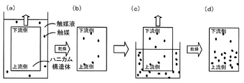
- the catalyst component is brought into contact with the entire honeycomb structure, and further, the catalyst component is brought into contact only with the upstream side to form a catalyst. In this way, the amount of catalyst on the upstream side is made larger than that on the downstream side.
- a honeycomb filter manufacturing method of the present invention it is possible to manufacture a honeycomb filter capable of suppressing an increase in pressure loss and further improving purification efficiency and temperature rise performance.
- the catalyst amount in the upstream partition wall portion, which is the partition wall portion on the upstream side of the cell is a
- the catalyst amount in the downstream partition wall portion, which is the partition wall portion on the downstream side of the cell is b.
- the catalyst is preferably formed so as to satisfy 05 ⁇ a / b ⁇ 3.00.
- either the overall catalyst forming step of forming the catalyst by bringing the whole into contact with the catalyst component or the partial catalyst forming step of forming the catalyst by contacting the catalyst component only on the upstream side may be preceded by the whole catalyst. It is preferable to precede the forming step. Further, the entire catalyst forming step may be performed before the collecting layer forming step, or may be performed after the collecting layer forming step. Further, the partial catalyst forming step may be performed before the collecting layer forming step or may be performed after the collecting layer forming step. When the partial catalyst formation step is performed after the collection layer formation step, the particle size of the catalyst component is smaller than the particle size of the collection layer, and is formed on the partition wall through the collection layer. Is preferred.
- the manufacturing method of the honeycomb filter of the present invention A method for manufacturing a honeycomb filter for collecting and removing a solid component contained in a fluid, A solid contained in a fluid in a honeycomb structure including a plurality of porous partition walls forming a plurality of cells serving as fluid flow paths having one end opened and the other end plugged A collecting layer forming step of forming a collecting layer which is a layer for collecting and removing the components; An upstream catalyst forming step of forming a catalyst by contacting the catalyst component only on the upstream side of the honeycomb structure; and A downstream catalyst forming step of forming a catalyst by contacting a catalyst component having a lower concentration than the catalyst component only on the downstream side of the honeycomb structure; and May be included.
- a high concentration catalyst is brought into contact with the upstream side of the honeycomb structure, and a low concentration catalyst is brought into contact with the downstream side to form a catalyst component. Even in this case, the amount of the catalyst supported on the upstream side can be made larger than that on the downstream side.
- the upstream side catalyst formation step in which the catalyst is formed by contacting the catalyst component only on the upstream side and the downstream side catalyst formation step in which the catalyst is formed by contacting the catalyst component only on the downstream side whichever comes first Good.
- the upstream catalyst formation step may be performed before the collection layer formation step or after the collection layer formation step.
- the downstream side catalyst formation step may be performed before the collection layer formation step or after the collection layer formation step.
- FIG. 3 is an explanatory diagram illustrating an example of a schematic configuration of a honeycomb filter 20.
- FIG. FIG. 3 is an explanatory diagram showing an example of a schematic vertical section of a honeycomb segment 21. It is explanatory drawing of the calculation method of the collection layer thickness by SEM observation.
- 4 is a schematic diagram illustrating an example of a catalyst distribution of the honeycomb filter 20.
- FIG. 4 is a schematic diagram illustrating an example of a catalyst distribution of the honeycomb filter 20.
- FIG. 4 is a schematic diagram illustrating an example of a catalyst distribution of the honeycomb filter 20.
- FIG. It is explanatory drawing of the measurement position of a catalyst amount. 4 is an explanatory diagram showing an example of an outline of a method for manufacturing a honeycomb filter 20.
- FIG. FIG. 3 is an explanatory diagram showing an example of a schematic configuration of a honeycomb filter 20.
- FIG. FIG. 3 is an explanatory diagram showing an example of a schematic vertical section of a honeycomb
- FIG. 4 is an explanatory view showing a state where the upstream side of the honeycomb filter 20 is brought into contact with a catalyst component.
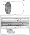
- 3 is an explanatory diagram illustrating an example of a schematic configuration of a honeycomb filter 40.
- FIG. It is explanatory drawing which shows the outline of a structure of the collection layer forming apparatus.
- the honeycomb filter of the present invention is disposed, for example, in an exhaust pipe of an engine for exhaust purification of an automobile engine, and collects a solid component (particulate matter, hereinafter also referred to as PM) contained in the exhaust. ⁇ To be removed.
- a process for burning the collected PM by increasing the fuel concentration is executed.
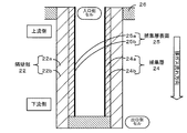
- FIG. 1 is an explanatory diagram showing an example of a schematic configuration of a honeycomb filter 20 according to an embodiment of the present invention.
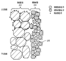
- FIG. 2 is an explanatory diagram showing an example of a schematic vertical cross section of the honeycomb segment 21.
- FIG. 3 is an explanatory diagram of a method for calculating the collection layer thickness by SEM observation.
- 4 to 6 are schematic views showing an example of the catalyst distribution of the honeycomb filter 20 of the present invention. It is explanatory drawing which shows an example of the outline of a structure of the honey-comb filter 40 which is one Embodiment of this invention.
- FIG. 7 is an explanatory view of the measurement position of the catalyst amount.
- FIG. 8 is an explanatory view showing an example of the outline of the manufacturing method of the honeycomb filter 20, and
- FIG. 9 is an explanatory view showing a state in which the upstream side of the honeycomb filter 20 is brought into contact with the catalyst component.
- the honeycomb filter 20 of the present embodiment has a shape in which the outer peripheral surfaces of two or more honeycomb segments 21 having partition walls 22 are bonded to each other by a bonding layer 27, and the outer peripheral protection portion is formed on the outer periphery thereof. 28 is formed.
- the honeycomb filter 20 has a porous partition wall in which one end portion is opened and the other end portion is plugged by a plugging portion 26 to form a plurality of cells 23 serving as exhaust gas flow paths as fluid.
- a collection layer 24 that is a layer that is formed on the partition wall 22 and collects and removes the solid component (PM) contained in the fluid (exhaust gas).
- the partition wall 22 includes a cell 23 in which one end is opened and the other end is plugged, and a cell in which one end is plugged and the other end is opened. 23 are alternately arranged. Further, in the honeycomb filter 20, the exhaust gas that has entered the cell 23 (also referred to as an inlet-side cell) having an opening on the inlet side passes through the collection layer 24 and the partition wall 22, and the cell 23 (the outlet-side cell) has an opening on the outlet side. The PM contained in the exhaust gas is collected on the collection layer 24 at this time.
- the outer shape of the honeycomb filter 20 is not particularly limited, but may be a columnar shape, a quadrangular columnar shape, an elliptical columnar shape, a hexagonal columnar shape, or the like.
- the outer shape of the honeycomb segment 21 is not particularly limited, but preferably has a flat surface that can be easily joined, and can have a polygonal prismatic shape (such as a quadrangular prism shape or a hexagonal prism shape).
- the cell may have a cross-sectional shape of a polygon such as a triangle, a quadrangle, a hexagon, and an octagon, a streamline shape such as a circle and an ellipse, and a combination thereof.
- the cell 23 may have a quadrangular cross section perpendicular to the flow direction of the exhaust gas.
- the outer shape of the honeycomb filter 20 is formed in a cylindrical shape
- the outer shape of the honeycomb segment 21 is formed in a rectangular column shape
- the cells 23 are formed in a rectangular shape will be mainly described.
- the cell pitch is preferably 1.0 mm or more and 2.5 mm or less.
- the pressure loss during PM deposition shows a smaller value as the filtration area is larger.
- the initial pressure loss increases as the cell diameter decreases. Therefore, the cell pitch, the cell density, and the thickness of the partition wall 22 may be set in consideration of the trade-off between the initial pressure loss, the pressure loss during PM deposition, and the PM collection efficiency.
- the partition wall 22 is porous and is selected from, for example, cordierite, Si-bonded SiC, recrystallized SiC, aluminum titanate, mullite, silicon nitride, sialon, zirconium phosphate, zirconia, titania, alumina, and silica. It is good also as what is formed including the above inorganic materials. Of these, cordierite, Si-bonded SiC, recrystallized SiC, and the like are preferable.
- the partition wall 22 preferably has a porosity of 30% by volume to 85% by volume, and more preferably 35% by volume to 65% by volume.
- the partition wall 22 preferably has an average pore diameter in the range of 10 ⁇ m to 60 ⁇ m.
- the partition wall 22 has a thickness of preferably 150 ⁇ m or more and 600 ⁇ m or less, and more preferably 200 ⁇ m or more and 400 ⁇ m or less. If the thickness is 150 ⁇ m or more, the mechanical strength can be increased, and if it is 600 ⁇ m or less, the pressure loss can be further reduced. When the partition wall portion 22 is formed with such a porosity, average pore diameter, and thickness, the exhaust gas easily passes and PM is easily collected and removed.
- the collection layer 24 is a layer that collects and removes PM contained in the exhaust gas, and is formed on the partition wall portion 22 by a group of particles having an average particle diameter smaller than the average pore diameter of the partition wall portion 22. It may be a thing.
- the collection layer 24 preferably has an average pore diameter of 0.2 ⁇ m or more and 10 ⁇ m or less, and preferably has a porosity of 40 volume% or more and 95 volume% or less, and the average particle size of the particles constituting the collection layer
- the diameter is preferably 0.5 ⁇ m or more and 15 ⁇ m or less. If the average pore diameter is 0.2 ⁇ m or more, it is possible to suppress an excessive initial pressure loss in which no PM is deposited.
- the average pore diameter is 10 ⁇ m or less, the PM collection efficiency is improved. It is possible to suppress PM from passing through the layer 24 and into the pores, and it is possible to suppress deterioration in pressure loss during PM deposition. Further, when the porosity is 40% by volume or more, it is possible to suppress an excessive initial pressure loss in which PM is not deposited, and when the porosity is 95% by volume or less, the durable collection layer 24 is used. A surface layer can be produced. Moreover, if the average particle size of the particles constituting the collection layer is 0.5 ⁇ m or more, the size of the space between the particles of the particles constituting the collection layer can be sufficiently secured, so that the permeability of the collection layer can be increased.
- the average thickness of the collection layer 24 is preferably 10 ⁇ m or more and 80 ⁇ m or less. When the thickness of the collection layer is 10 ⁇ m or more, PM is easily collected, and when it is 80 ⁇ m or less, the resistance of the fluid to pass through the partition wall can be further reduced, and the pressure loss can be further reduced.
- the average thickness of the collection layer is more preferably 20 ⁇ m or more and 60 ⁇ m or less, and further preferably 30 ⁇ m or more and 50 ⁇ m or less. Further, in order to suppress the trapping of the PM by the trapping layer and the intrusion of the PM into the partition wall portion 22, the catalyst supported in the partition wall portion 22 among the catalysts described later, for example, the sulfur content The poisoning of the catalyst by direct contact with PM containing can be suppressed.
- the collection layer 24 may be formed on the partition wall 22 of the inlet side cell and the outlet side cell of the exhaust gas, but is formed on the partition wall 22 of the inlet side cell as shown in FIG. It is preferable that the outlet side cell is not formed. In this way, the pressure loss can be further reduced and PM contained in the fluid can be removed more efficiently.
- the honeycomb filter 20 can be easily manufactured.
- the downstream collection layer 24b may be thicker than the upstream collection layer 24a. This is because if the downstream collection layer 24b is thickened, a larger amount of fluid can be circulated through the upstream partition wall portion having a small permeation resistance.
- This collection layer 24 is formed by including one or more inorganic materials selected from cordierite, SiC, mullite, aluminum titanate, alumina, silicon nitride, sialon, zirconium phosphate, zirconia, titania and silica. It may be a thing.
- the collection layer 24 is preferably formed of the same material as the partition wall 22.
- the collection layer 24 more preferably contains 70% by weight or more of ceramic or metal inorganic fibers. If it carries out like this, it will be easy to collect PM by fiber.
- the collection layer 24 may be formed by including one or more materials in which the inorganic fibers are selected from aluminosilicate, alumina, silica, zirconia, ceria, and mullite.
- the average particle diameter of the particle group of the collection layer 24 was obtained by observing the collection layer 24 with a scanning electron microscope (SEM) and measuring each particle of the collection layer 24 included in the photographed image. It shall mean the average value.
- the average particle diameter of the raw material particles is the median diameter (D50) obtained by measuring the raw material particles using water as a dispersion medium using a laser diffraction / scattering particle size distribution measuring apparatus.
- the collection layer 24 may be formed on the surface of the cell 23 using a slurry containing inorganic particles as a raw material of the collection layer 24 or an inorganic material used as a raw material of the collection layer 24. Fine particles of particles or the like may be formed on the surface of the cell 23 by flowing into the cell with gas.
- the inorganic particles may be the inorganic material described above, and preferably have an average particle size smaller than the average pore size of the partition walls.
- the thickness of the collection layer 24 in other words, the thickness of the particle group constituting the collection layer is obtained as follows.
- an observation sample polished after the partition wall substrate of the honeycomb filter 20 is filled with resin is prepared, and the thickness of the collection layer is determined by analyzing an image obtained by observation with a scanning electron microscope (SEM).
- SEM scanning electron microscope
- the magnification of the SEM is set to 100 to 500 times, and an observation surface of an observation sample prepared with a visual field in the range of about 500 ⁇ m ⁇ 500 ⁇ m is photographed at a measurement position described later.
- the outermost contour line of the partition wall is virtually drawn in the photographed image.
- the outermost contour line of the partition wall is a line indicating the contour of the partition wall, and the partition surface is irradiated with virtual parallel light from a direction perpendicular to the partition surface (irradiation surface, refer to the upper part of FIG. 3). It is assumed that the projection line obtained when the above is performed (see the middle of FIG. 3). That is, the outermost contour line of the partition wall is formed by the line segments on the upper surfaces of the plurality of partition walls having different heights and the perpendicular lines connecting the line segments on the upper surfaces of the partition walls having different heights. Is done.
- the line segment on the upper surface of the partition wall is drawn with “5% resolution” ignoring unevenness of 5 ⁇ m or less with respect to the line segment of 100 ⁇ m length, and the horizontal line segment becomes finer. Shall not be too much.
- the outermost contour line of the partition wall is drawn, the presence of the collection layer is ignored.
- the outermost contour line of the particle group forming the collection layer is virtually drawn.
- the outermost contour line of the particle group is a line indicating the contour of the trapping layer, and it is assumed to be virtual on the trapping layer surface from a direction perpendicular to the trapping layer surface (irradiation surface, see the upper part of FIG. 3).
- the outermost contour line of the particle group is a perpendicular line that connects each of the line segments on the upper surface of a plurality of particle groups with different heights and the line segment of the upper surface of the particle group with different heights adjacent to each other. And formed.
- the line segment on the upper surface of the particle group is drawn with the same “resolution” as the partition wall.
- a highly porous collection layer if an observation sample is prepared by embedding the resin and polishing it, some particles may be observed as floating in the air.
- the outermost contour line is drawn using the line.
- a standard reference line of the partition which is an average line of the outermost contour lines of the partition walls is obtained based on the height and length of the upper surface segment of the outermost contour line of the drawn partition walls (see the lower part of FIG. 3).
- the particle group which is an average line of the outermost contour lines of the particle group based on the height and length of the upper surface line segment of the outermost contour line of the drawn particle group.
- the average height is obtained (see the lower part of FIG. 3).
- the difference of the average height of the obtained particle group and the standard reference line of a partition is taken, and this difference (length) is made into the thickness (thickness of particle group) of the collection layer in this picked-up image. In this way, the thickness of the collection layer can be determined.
- the average pore diameter and porosity of the collection layer 24 shall be determined by image analysis by SEM observation. Similar to the thickness of the trapping layer described above, as shown in FIG. 3, the cross section of the honeycomb filter 20 is imaged by SEM to obtain an image. Next, a region formed between the outermost contour line of the partition wall and the outermost contour line of the particle group is defined as a region occupied by the collection layer (collection layer region). A region where the particle group exists is referred to as a “particle group region”, and a region where the particle group does not exist is referred to as a “pore region of the collection layer”.
- region are calculated
- the particle group area is divided by the collection layer area and multiplied by 100 to obtain the obtained value as the porosity of the collection layer.
- an inscribed circle inscribed in the outermost contour lines of the particle group and the partition wall and the outer periphery of the particle group is drawn so as to maximize the diameter.
- a plurality of inscribed circles can be drawn in one “trapping layer pore region”, such as a rectangular pore region having a large aspect ratio, the inner diameter is as large as possible so that the pore region is sufficiently filled.
- a plurality of tangent circles shall be drawn. Then, in the observed image range, the average value of the diameter of the drawn inscribed circle is set as the average pore diameter of the collection layer. In this way, the average pore diameter and porosity of the collection layer 24 can be determined.
- the partition part 22 contains a catalyst.
- the collection layer 24 is good also as a thing containing a catalyst.
- This catalyst is at least one of a catalyst that oxidizes unburned gas (such as HC and CO) contained in exhaust gas, a catalyst that promotes combustion of collected PM, and a catalyst that absorbs / adsorbs / decomposes NOx. Also good. In this way, it is possible to efficiently oxidize unburned gas, efficiently remove PM, and efficiently decompose NOx.
- this catalyst for example, it is more preferable to contain one or more kinds of noble metal elements and transition metal elements.
- the honeycomb filter 20 may carry another catalyst or a purification material.
- NO x storage catalyst containing alkali metals (Li, Na, K, Cs, etc.) and alkaline earth metals (Ca, Ba, Sr, etc.), at least one rare earth metal, transition metal, three-way catalyst, cerium
- examples thereof include promoters represented by oxides of (Ce) and / or zirconium (Zr), and HC (Hydro Carbon) adsorbents.
- examples of the noble metal include platinum (Pt), palladium (Pd), rhodium (Rh), gold (Au), and silver (Ag).
- the transition metal contained in the catalyst include Mn, Fe, Co, Ni, Cu, Zn, Sc, Ti, V, and Cr.
- rare earth metals include Sm, Gd, Nd, Y, La, Pr, and the like.
- alkaline earth metal examples include Mg, Ca, Sr, Ba and the like. Of these, platinum and palladium are more preferred.
- noble metals, transition metals, promoters and the like may be supported on a carrier having a large specific surface area.
- alumina, silica, silica alumina, zeolite or the like can be used. If it has a catalyst that promotes combustion of PM, PM collected on the collection layer 24 can be removed more easily, and a catalyst that oxidizes unburned gas and a catalyst that decomposes NOx If it has, exhaust gas can be further purified.
- the catalyst may be supported uniformly in the thickness direction in the partition wall 22.
- the catalyst may be supported uniformly in the thickness direction in the collection layer 24.
- “the catalyst is uniform in the thickness direction” means that the amount of the catalyst in the direction perpendicular to the partition wall surface is uniform, and may be completely uniform or may vary to some extent. Good.
- the difference in the catalyst amount between the portion where the catalyst amount is maximum and the portion where the catalyst amount is minimum in the direction perpendicular to the partition wall surface can be 0.2 g / L or less, or 0.1 g / L or less.
- the upstream partition wall portion 22a may refer to, for example, the range of the upstream side 1/3 in the exhaust gas flow direction.
- the downstream partition wall portion 22b may be, for example, a range of 1/3 downstream in the exhaust gas flow direction.
- the catalyst amount a and the catalyst amount b satisfy 1.5 ⁇ a / b ⁇ 3.0. This is because the purification efficiency and the temperature rise performance can be further increased.
- the “catalyst amount in the partition wall portion” refers to the catalyst amount (mass%) obtained by elemental analysis under electron microscope observation. Note that the catalyst amount (mass%) is multiplied by the total weight of the honeycomb filter to be measured and divided by the volume of the honeycomb filter to obtain an apparent catalyst amount (g / g) per unit volume in the measurement unit. L).
- This “catalyst amount” is sufficient if the relative relationship between the catalyst amount “a” and the catalyst amount “b” can be grasped, and the amount of a specific catalyst component, for example, a noble metal element such as Pt or Pd is obtained by elemental analysis with direct electron microscope observation. Alternatively, for example, an amount obtained by elemental analysis under electron microscope observation of a catalyst carrier on which a noble metal element such as alumina is supported may be used in place of the amount of noble metal element. When the same element as the catalyst support (for example, alumina) is a constituent element of the partition wall, the relative relationship between the catalyst amount a and the catalyst amount b should be obtained using the measurement result of the catalyst component (noble metal etc.). That's fine.
- the catalyst amount of the upstream partition wall portion 22a is larger than the catalyst amount of the downstream partition wall portion 22b, and the upstream side and downstream side catalyst are collected on the collection layer 24 and the collection layer surface 25.
- the amount is uniform.
- the collection layer 24 may support the catalyst uniformly.
- the collection layer 24 may not carry a catalyst. This is because the increase in pressure loss can be suppressed and the purification efficiency and the temperature rise performance can be improved.
- the catalyst is uniform means that there is no difference in the catalyst amount between the upstream side and the downstream side. For example, the difference in the catalyst amount between the upstream side and the downstream side is 0.02 g / L or less, 0 0.01 g / L or less.
- the catalyst amount of the upstream partition wall portion 22a is larger than the catalyst amount of the downstream partition wall portion 22b, and the catalyst amount of the upstream collection layer 24a is the catalyst amount of the downstream collection layer 24b. More than that, the amount of catalyst on the upstream side and the downstream side is uniform on the collection layer surface 25.
- a catalyst is supported at least in part, and when the catalyst amount of the upstream collection layer 24 a is A and the catalyst amount of the downstream collection layer 24 b is B, 1 It is preferable to satisfy 0.08 ⁇ A / B ⁇ 5.00. This is because the purification efficiency can be further increased.
- the purification efficiency can be further increased.
- the “catalyst amount of the collection layer” is the same as the “catalyst amount of the partition wall”, and is the amount of catalyst supported on the collection layer, and the catalyst amount per unit volume (L) of the honeycomb filter. It may be the weight (g).
- the catalyst amount of the upstream partition wall portion 22a is larger than the catalyst amount of the downstream partition wall portion 22b, and the catalyst amount of the upstream collection layer 24a is larger than the catalyst amount of the downstream collection layer 24b.
- the amount of catalyst on the upstream collection layer surface 25a is larger than the amount of catalyst on the downstream collection layer surface 25b.
- the catalyst is supported on the collection layer surface 25, the catalyst amount on the upstream collection layer surface 25a is A S , and the catalyst amount on the downstream collection layer surface 25b is B.
- S it is more preferable that 1.10 ⁇ A S / B S ⁇ 8.00.
- the temperature raising performance can be further increased and the regeneration efficiency in the regeneration process can be further increased.
- 1.50 ⁇ A S / B S ⁇ 8.00 is more preferable, and 3.00 ⁇ A S / B S ⁇ 8.00 is more preferable.
- the temperature raising performance can be further increased and the regeneration efficiency in the regeneration process can be further increased.
- the exhaust gas entering the cell comes into contact with the catalyst earlier and generates heat of oxidation, the propagation of this heat causes the entire honeycomb filter to reach a high temperature earlier, and the temperature rise performance can be further improved. It is thought that efficiency can be improved.
- the “catalyst amount on the surface of the collection layer” is the same as the “catalyst amount on the partition wall portion”, and is the amount of catalyst supported on the surface of the collection layer, per unit volume (L) of the honeycomb filter.
- the weight (g) of the catalyst may be referred to.
- the honeycomb filter 20 may carry a catalyst as shown in FIGS. 4 to 6 described above. However, as long as the catalyst amount of the upstream partition wall portion 22a and the downstream partition wall portion 22b satisfies the relationship described above.
- the catalyst in the collection layer 24 and the collection layer surface 25 is not particularly limited.
- the catalyst may not be formed inside the collection layer 24 and may be formed only on the collection layer surface 25, or the catalyst may not be formed on the collection layer surface 25 and collected.
- a catalyst may be formed only inside the layer 24.
- the catalyst amount of the downstream collection layer 24b may be larger than the upstream collection layer 24a, or the catalyst amount of the downstream collection layer 25b may be greater than the upstream collection layer surface 25a.
- the catalyst may be one in which the amount of the catalyst varies in the thickness direction of the partition wall or the collection layer.
- the measurement positions of the downstream catalyst amounts b, B, B S are the center point and the center point in the cross section at about 1/6 of the total length from the downstream end face of the honeycomb filter 20.
- the five points including any four points located on the top, bottom, left and right with respect to the center point are defined as the catalyst amount. Measurement shall be performed as follows. First, as a sample for measuring the catalyst amounts a and b of the partition wall portion 22 and the catalyst amounts A and B of the trapping layer 24, the partition wall substrate of the honeycomb filter 20 has a measurement cross section (XY plane) as a measurement surface. Prepare a material that is cut out and polished after resin filling. Further, as a sample for measuring the catalyst amounts A S and B S on the collection layer surface 25, a partition wall substrate of the honeycomb filter 20 cut out so that the surface (film surface) of the collection layer 24 becomes the measurement surface is used. prepare.
- SEM scanning electron microscope
- the amount of catalyst is calculated by performing elemental analysis in the observed region.
- the magnification of the SEM is preferably 100 to 1000 times.
- an energy dispersive X-ray analyzer (EDX) or an electron probe microanalyzer (EPMA) can be used for elemental analysis.
- EDX measurement scan measurement in the observation visual field is performed, and the obtained value (mass%) is used as the concentration in the measurement region, and the relative relationship between each measurement unit is determined by comparing the values at each measurement site with each other. It may be evaluated.
- the precious metal component (hereinafter also referred to as PGM) in the catalyst may be measured, or the amount of alumina as a support for the precious metal component may be measured, and this may be used as the catalyst amount corresponding to the content of the precious metal component. .
- elemental analysis is performed at an arbitrary position of 5 to 10 points in the observation visual field, and the most classified among the detected components classified as catalyst components is determined as the catalyst carrier, and the catalyst The mass% of the carrier is treated as the amount of catalyst in the observation field. For example, if an oxidation catalyst is coated and the detected catalyst component has the largest amount of alumina, the amount of alumina may be handled as the catalyst amount.
- the mass% of the catalyst component (for example, Pt) in the coated catalyst may be handled as the catalyst amount in the measurement region.
- the mass% value obtained by EDX is used as it is. It may be used for comparison.
- the mass amount may be handled as an apparent catalyst amount per unit volume by multiplying the total weight of the honeycomb filter to be measured and dividing by the volume of the honeycomb filter.
- the bonding layer 27 is a layer for bonding the honeycomb segments 21 and may include inorganic particles, inorganic fibers, a binder, and the like.
- the inorganic particles can be the particles of the inorganic material described above, and the average particle diameter is preferably 0.1 ⁇ m or more and 30 ⁇ m or less.
- the inorganic fiber may be as described above.
- the average diameter is preferably 0.5 ⁇ m to 8 ⁇ m, and the average length is preferably 100 ⁇ m to 500 ⁇ m.
- colloidal silica or clay can be used as the binder.
- the bonding layer 27 is preferably formed in a range of 0.5 mm to 2 mm.
- an average particle diameter shall mean the median diameter (D50) measured using the laser diffraction / scattering type particle size distribution measuring apparatus and water as a dispersion medium.
- the outer periphery protection part 28 is a layer that protects the outer periphery of the honeycomb filter 20 and may include the above-described inorganic particles, inorganic fibers, a binder, and the like.
- the coefficient of thermal expansion in the direction of the passage hole of the cell 23 at 40 ° C. to 800 ° C. is preferably 6.0 ⁇ 10 ⁇ 6 / ° C. or less, and 1.0 ⁇ 10 ⁇ 6 / ° C. or less. More preferably, it is 0.8 ⁇ 10 ⁇ 6 / ° C. or less.
- the thermal expansion coefficient is 6.0 ⁇ 10 ⁇ 6 / ° C. or less, the thermal stress generated when exposed to high-temperature exhaust can be suppressed within an allowable range.
- the method for manufacturing the honeycomb filter 20 includes, for example, a partition wall that forms a porous partition wall portion 22 in which one end portion is opened and the other end portion is plugged to form a plurality of cells serving as fluid flow paths.
- Part forming step, collecting layer forming step for forming the collecting layer 24 for collecting and removing PM contained in the exhaust, one end is opened and the other end is plugged, and the flow of fluid A honeycomb structure having a plurality of porous partition walls that form a plurality of cells serving as paths, and an overall catalyst forming step of forming a catalyst by bringing the whole into contact with a catalyst component; A portion in which a honeycomb structure including a plurality of porous partition walls that form a plurality of cells that are plugged at the other end and serve as fluid flow paths is brought into contact with a catalyst component only on the upstream side to form a catalyst. And a catalyst formation step.
- the raw material of the partition wall 22 is mixed, and the partition wall 22 is formed by a predetermined forming method.
- the partition wall 22 is formed along with the formation of a honeycomb formed body that is a formed body before the collection layer 24 is formed and before firing.
- a raw material for the partition wall 22 for example, a base material, a pore former, and a dispersion medium may be mixed to prepare clay or slurry.
- a base material the inorganic material mentioned above can be used.
- SiC powder and metal Si powder are mixed at a mass ratio of 80:20, a dispersion medium such as water and a pore forming material are added, and an organic binder is further added thereto. And kneaded to form a plastic clay.
- the means for preparing the clay by kneading the SiC powder and the metal Si powder raw material (molding raw material) is not particularly limited, and examples thereof include a method using a kneader or a vacuum kneader.
- the pore former those that burn after firing are preferable. For example, starch, coke, foamed resin, and the like can be used.
- the partition wall 22 may be formed as a honeycomb formed body by extruding into an arbitrary shape described above using a mold having a shape in which the cells 23 are arranged side by side. Then, the process which forms the plugging part 26 in a honeycomb molded object is performed.
- the plugged portion 26 includes a cell 23 in which one end is opened and the other end is plugged, and a cell 23 in which one end is plugged and the other end is opened. Are preferably alternately arranged.
- a raw material for forming the partition wall 22 described above may be used as a raw material used for plugging.
- the obtained honeycomb formed body is preferably subjected to a drying treatment, a calcination treatment, and a firing treatment.
- the calcination process is a process of burning and removing organic components contained in the honeycomb formed body at a temperature lower than the firing temperature.
- the firing temperature can be 1400 ° C. to 1450 ° C. for cordierite raw material, and 1450 ° C. for Si-bonded SiC.
- the honeycomb structure before forming the collection layer 24 can be obtained.
- the honeycomb structure here may be one that forms the honeycomb segment 21 or may form the honeycomb filter 20 in which a plurality of honeycomb segments 21 are joined.
- the trapping layer forming step may be performed by a wet method or a dry method.
- the collection layer 24 may be formed so that the downstream collection layer 24b of the honeycomb filter 20 is thicker than the upstream collection layer 24a.
- the average thickness of the collection layer 24 is preferably 10 ⁇ m or more and 80 ⁇ m or less. When the thickness of the collection layer is 10 ⁇ m or more, PM is easily collected, and when it is 80 ⁇ m or less, the resistance of the fluid to pass through the partition wall can be further reduced, and the pressure loss can be further reduced.
- the average thickness of the collection layer is more preferably 20 ⁇ m or more and 60 ⁇ m or less, and further preferably 30 ⁇ m or more and 50 ⁇ m or less.
- a collection layer 24 may be formed by preparing a slurry containing the raw material of the collection layer 24 and supplying the slurry to the cell 23.
- This slurry may be prepared by mixing inorganic fibers, a binder, a binder, and a dispersion medium as a raw material for the collection layer 24, for example.
- the inorganic fibers those described above can be used.
- an average particle diameter shall mean the median diameter (D50) measured using the laser diffraction / scattering type particle size distribution measuring apparatus and water as a dispersion medium.
- the solid content contained in the slurry may be formed on the partition wall 22 by suction from the outlet side of the cell 23, or the slurry may be pumped from the inlet side of the cell 23.
- the solid content contained in the slurry may be formed on the partition wall 22.
- the latter can make the thickness of the collection layer 24 more uniform.
- the collection layer 24 is preferably fixed by drying and heat treatment after forming a raw material layer on the partition wall 22.
- a temperature in the heat treatment for example, a temperature of 200 ° C. or higher and 900 ° C. or lower is preferable, and a temperature of 650 ° C. or higher and 750 ° C. or lower is more preferable.
- the heat treatment temperature is 200 ° C. or higher, the contained organic substances can be sufficiently removed, and when the heat treatment temperature is 900 ° C. or lower, pore reduction can be suppressed.
- the collection layer forming step is performed by a dry method, for example, gas (air) may be used as a raw material transport medium for the collection layer, and a gas containing the collection layer material may be supplied to the inlet cell.
- gas air
- the particle group constituting the collection layer is formed more coarsely, a collection layer having an extremely high porosity can be produced, which is preferable.
- the raw material for the collection layer for example, inorganic fibers or inorganic particles may be used.
- the inorganic fibers those described above can be used. For example, those having an average diameter of 0.5 ⁇ m to 8 ⁇ m and an average length of 100 ⁇ m to 500 ⁇ m are preferable.
- the above-described inorganic material particles can be used.
- SiC particles or cordierite particles having an average particle size of 0.5 ⁇ m or more and 15 ⁇ m or less can be used.
- the material for the collection layer preferably has an average particle size smaller than the average pore size of the partition wall 22. At this time, it is preferable to use the same inorganic material for the partition wall 22 and the collection layer 24.
- a binder may be supplied together with inorganic fibers and inorganic particles.
- the binder can be selected from sol materials and colloidal materials, and colloidal silica is particularly preferably used.
- the inorganic particles are preferably coated with silica, and the inorganic particles and the inorganic particles and the partition wall material are preferably bonded with silica.
- an oxide material such as cordierite or aluminum titanate
- the collection layer 24 is preferably bonded by forming a raw material layer on the partition wall 22 and then performing a heat treatment.
- a temperature in the heat treatment for example, a temperature of 650 ° C. or higher and 1350 ° C. or lower is preferable. When the heat treatment temperature is 650 ° C. or higher, sufficient bonding strength can be secured, and when it is 1350 ° C. or lower, pore clogging due to excessive oxidation of particles can be suppressed.
- the entire catalyst structure is formed by bringing the honeycomb structure into contact with the catalyst component to form a catalyst, and the partial catalyst forming step in which the catalyst is formed by contacting the catalyst component only on the upstream side.
- the whole catalyst forming step and the partial catalyst forming step may be performed after the partition wall forming step and before the collecting layer forming step, or may be performed after the collecting layer forming step. Further, either the overall catalyst forming step or the partial catalyst forming step may be performed first.
- the overall catalyst formation step is performed first, for example, after the overall catalyst formation step, the overall catalyst drying step of drying the catalyst is performed, and then, after the partial catalyst formation step, the partial catalyst drying step of drying the catalyst is performed, Finally, a calcination step (heat treatment step) for supporting the catalyst by calcination or heat treatment at a high temperature may be performed. Moreover, it is good also as what performs the baking process (heat treatment process) which carries a catalyst by baking or the heat processing at high temperature after the whole catalyst formation process, performs a partial catalyst formation process after that, and also performs a baking process (heat treatment process). The same applies to the case where the partial catalyst forming step is performed first.
- disassembles NOx, etc. which were mentioned above can be selected suitably.
- the method for forming the catalyst is not particularly limited.
- a catalyst solution containing a catalyst component may be wash coated on the trapping layer 24 of the honeycomb structure, or a conventionally known ceramic film such as a dipping method may be used. A forming method may be used. At this time, the amount of catalyst can be adjusted to a desired value by controlling the concentration of the catalyst solution containing the catalyst, the time required for catalyst loading, and the like.
- catalyst components such as a catalyst that oxidizes unburned gas and a catalyst that decomposes NOx are supported in a highly dispersed state. Therefore, after being previously supported on a heat-resistant inorganic oxide having a large specific surface area such as alumina, You may carry
- the catalyst is formed by, for example, a method in which a catalyst slurry is supported in the partition walls and / or the pores of the PM collection layer by applying a conventionally known catalyst supporting method such as a suction method, and is dried and calcined. May be.
- a container filled with a catalyst solution containing a catalyst is prepared so that the entire honeycomb structure is immersed, and the entire honeycomb structure is immersed therein (see FIG. 8A).
- the honeycomb structure immersed for a predetermined time is pulled up from the container, and the catalyst component is sufficiently dried (see FIG. 8B).
- the catalyst is uniformly formed on both the upstream side and the downstream side of the honeycomb structure. Also, by drying the catalyst, elution of the catalyst component formed in the overall catalyst formation step can be suppressed in the partial catalyst formation step.
- a container filled with the catalyst solution is prepared so that the upstream side of the honeycomb structure is immersed, and the upstream side of the honeycomb structure is immersed therein (see FIG. 8C).
- the honeycomb structure immersed for a predetermined time is pulled up from the container, and the catalyst component is sufficiently dried (see FIG. 8D).
- FIG. 8D As a result, further catalyst is formed on the upstream side of the honeycomb structure, and the amount of catalyst on the upstream side increases. If the concentration of the catalyst in the catalyst solution that immerses the upstream side is set higher, the concentration of the upstream catalyst can be increased more easily than the downstream side.
- the upstream side of the honeycomb structure is immersed in the catalyst solution as shown in FIG.
- the plugging portion 26 is provided not only on the cell in which the catalyst solution side is open but also on the catalyst solution side. Since the catalyst solution also enters the cells that have them (see FIG. 9), the catalyst components are uniformly formed on the entire upstream side. At this time, it is preferable that the catalyst particles have a particle size smaller than the pores in the partition walls and can pass through the partition walls.
- the honeycomb filter 20 is manufactured by, for example, forming a porous partition wall portion 22 having one end opened and the other end plugged to form a plurality of cells serving as fluid flow paths.
- a honeycomb structure having a plurality of porous partition walls forming a plurality of cells that are opened and the other end is plugged to form a fluid flow path is formed at a lower concentration than the catalyst component only on the downstream side.
- a downstream catalyst forming step of forming a catalyst by contacting with the catalyst component of It may be as including.
- the partition wall forming step and the collection layer forming step can be performed in the same manner as described above.
- the upstream side catalyst forming step in which the honeycomb structure is brought into contact with the catalyst component only on the upstream side to form a catalyst, and the catalyst component having a lower concentration than the catalyst component in contact with the upstream side only on the downstream side.
- a downstream catalyst forming step is performed in which the catalyst is formed in contact with the catalyst component.
- the upstream catalyst forming step and the downstream catalyst forming step may be performed after the partition wall forming step and before the collecting layer forming step, or may be performed after the collecting layer forming step. Further, either the upstream catalyst forming step or the downstream catalyst forming step may be performed first.
- the upstream catalyst forming step is performed first, for example, after the upstream catalyst forming step, the upstream catalyst drying step for drying the catalyst is performed, and then the downstream catalyst for drying the catalyst after the downstream catalyst forming step is performed. It is good also as what performs a drying process and finally performs the baking process (heat treatment process) which carry
- a firing step for supporting the catalyst by firing or heat treatment at high temperature is performed, then the downstream catalyst formation step is performed, and further the firing step (heat treatment step) is performed. Good. The same applies when the downstream side catalyst formation step is performed first.
- disassembles NOx, etc. which were mentioned above can be selected suitably.
- the formation method of a catalyst can also use the method similar to the above-mentioned whole catalyst formation process or a partial catalyst formation process.
- the ratio between the catalyst amount a of the upstream partition wall portion 22a and the catalyst amount b of the downstream partition wall portion 22b is Since it is appropriate and has a collection layer that is a layer for collecting and removing solid components, it is possible to suppress an increase in pressure loss and to further improve purification efficiency and temperature rise performance.
- the honeycomb filter 20 is formed by bonding the honeycomb segments 21 with the bonding layer 27.
- an integrally formed honeycomb filter 40 may be used.
- the partition wall portion 42, the cell 43, the collection layer 44, the plugging portion 46, the outer periphery protection portion 48, and the like are the partition wall portion 22, the cell 23, the collection layer 24, and the plugging portion of the honeycomb filter 20.
- 26 and the outer periphery protection part 28 can be set as the same structure. Even if it does in this way, the raise of a pressure loss can be suppressed and purification efficiency and temperature rising performance can be improved more.
- the honeycomb filter 20 includes a catalyst.
- the honeycomb filter 20 is not particularly limited as long as the removal target substance included in the circulating fluid can be purified.
- the honeycomb filter 20 for automobiles has been described.
- the present invention is not particularly limited as long as the solid component contained in the fluid is collected and removed, and the honeycomb filter for a power generation engine may be used. Alternatively, it may be a honeycomb filter for construction equipment.
- honeycomb segments were produced as follows. SiC powder and metal Si powder are mixed at a mass ratio of 80:20, and methyl cellulose and hydroxypropoxyl methyl cellulose, a surfactant and water are added and kneaded to obtain a plastic clay, and a predetermined mold is obtained.
- a predetermined mold is obtained.
- the partition wall was formed into a shape having a thickness of 305 ⁇ m, a cross section of 35 mm ⁇ 35 mm, and a length of 152.4 mm.
- the obtained honeycomb segment formed body was dried by microwave, further dried with hot air, plugged, calcined in an oxidizing atmosphere at 550 ° C. for 3 hours, and then inert atmosphere
- the main baking was performed under the conditions of 1400 ° C. and 2 hours below.
- the plugging portion is formed by alternately masking the cell opening on one end face of the segment molded body, immersing the masked end face in a plugging slurry containing a SiC raw material, and then opening and plugging section. And were arranged alternately.
- the other end face is also masked so that one open and the other plugged cell and the one plugged and the other open cell are alternately arranged. Part was formed. In this way, honeycomb segments were produced.
- the porosity of the partition wall was 42%.
- the collection layer was formed by a wet method.
- SiC average particle size 15 ⁇ m
- carboxymethyl cellulose is 0.5% by weight as an organic binder
- colloidal silica is 2% by weight as a binder.
- water as a dispersion medium was mixed at 95% by weight to obtain a slurry for forming a collection layer.
- the collection layer was formed using the collection layer forming apparatus 50 shown in FIG. First, the jig 51 was fixed to one end of the manufactured honeycomb segment, and the supply fixing cylinder 54 was fixed to the other end of the honeycomb segment. A through hole 52 is formed in the center of the jig 51.
- a supply port 53 for supplying slurry is formed at the tip of the supply fixing cylinder 54.
- a supply amount adjusting plate 56 for adjusting the supply amount of the slurry is disposed between the supply fixing cylinder 54 and the honeycomb segment 21, a supply amount adjusting plate 56 for adjusting the supply amount of the slurry is disposed.
- the supply amount adjusting plate 56 is a member that adjusts the flow rate of the slurry.
- the supply amount adjusting plate 56 is fixed at a position obtained empirically in advance so that a predetermined film thickness is formed, and the slurry is pumped from the supply port 53 to form the plugging portion 26 on the supply port 53 side. Slurry was supplied to the inside of the cells of the non-honeycomb segment (the left figure of FIG. 11).
- the through hole 52 of the jig 51 was sucked, and water as a solvent for the slurry was discharged through the partition wall 22 (center view in FIG. 11).
- the solid content of the slurry remained inside the cell 23 having an opening on the supply fixing cylinder 54 side, and a collection layer was formed on the partition wall.
- the obtained honeycomb structure was dried with a hot air dryer and then heat treated at 700 ° C. for 1 hour to obtain a honeycomb segment in which a trapping layer was formed (the right diagram in FIG. 11).
- a bonding slurry formed by kneading alumina silicate fiber, colloidal silica, polyvinyl alcohol, silicon carbide, and water is applied to the side surface of the honeycomb segment on which the collection layer is formed, and after being assembled and pressure-bonded, heating is performed. It dried and the honeycomb segment bonded body whose whole shape is a square shape was obtained. Furthermore, after the honeycomb segment bonded body is ground into a cylindrical shape, the periphery thereof is coated with a slurry for outer periphery coating made of the same material as the bonding slurry, and cured by drying to have a desired shape and segment shape. A cylindrical honeycomb filter having a cell structure was obtained. Here, the honeycomb filter has a cross-sectional diameter of 143.8 mm and a length of 152.4 mm.
- a catalyst slurry was prepared by mixing the starting materials and water as a solvent.
- the catalyst slurry refers to this composition, and the catalyst particle size and concentration are appropriately adjusted and used.
- a catalyst whose particle size is smaller than the pore size of the collection layer and which can pass through the collection layer is small, and the pore size of the catalyst is larger than the pore size of the collection layer and is captured on the surface of the collection layer.
- the downstream end face of the honeycomb filter is immersed to a predetermined height in a catalyst slurry having a small particle size of a predetermined concentration, and suctioned from the upstream side for a predetermined time while adjusting to a predetermined suction pressure and suction flow rate.
- a catalyst was formed, dried at 120 ° C. for 2 hours, and baked at 550 ° C. for 1 hour. Note that the catalyst amount per unit volume of the honeycomb filter was set to 20 g / L as a whole (the same applies hereinafter).
- a honeycomb filter of Comparative Example 1 supporting the above was produced.
- Example 7 to 15 The downstream end face of the honeycomb filter is immersed to a predetermined height in a catalyst slurry of a small particle size with a predetermined concentration, and the catalyst is formed by suction from the upstream side for a predetermined time while adjusting the predetermined suction pressure and suction flow rate. And dried at 120 ° C. for 2 hours. Next, a catalyst is formed by immersing the upstream end face of the honeycomb filter to a predetermined height for a predetermined time in a catalyst slurry having a small particle diameter of a predetermined concentration, and then air is blown from the surface of the collection layer toward the partition wall.
- the collection layer and the catalyst on the surface of the collection layer were extruded into the partition wall and dried at 120 ° C. for 2 hours.
- the upstream side of the partition wall was fixed at a high concentration
- the surface of the collection layer and the surface of the collection layer were fixed at a uniform concentration on the upstream side and downstream side.
- a catalyst is formed by immersing the upstream end face of the honeycomb filter to a predetermined height for a predetermined time in a catalyst slurry having a small particle diameter at a predetermined concentration, and then air is blown from the surface of the collection layer toward the partition wall to capture the catalyst.
- the catalyst on the surface of the collection layer was extruded into the collection layer, dried at 120 ° C.
- Example 16 to 25 The downstream end face of the honeycomb filter is immersed to a predetermined height in a catalyst slurry of a small particle size with a predetermined concentration, and the catalyst is formed by suction from the upstream side for a predetermined time while adjusting the predetermined suction pressure and suction flow rate. And dried at 120 ° C. for 2 hours.
- a catalyst was formed by immersing the upstream end face of the honeycomb filter to a predetermined height for a predetermined time in a catalyst slurry having a small particle size of a predetermined concentration, and dried at 120 ° C. for 2 hours.
- the catalyst was fixed to the partition wall, the collection layer, and the surface of the collection layer so that the upstream side had a high concentration.
- a catalyst is formed by immersing the upstream end face of the honeycomb filter to a predetermined height in a catalyst slurry having a large particle size of a predetermined concentration for a predetermined time, drying at 120 ° C. for 2 hours, and baking at 550 ° C. for 1 hour. went.
- Example 26 A honeycomb filter of Example 26 was produced by the same process as Example 22 except that the trapping layer was formed by a dry method. Formation of the trapping layer in a dry process was performed as follows. First, air containing SiC particles having an average particle size smaller than the average pore diameter of the partition walls is introduced from the opening end portion on the exhaust gas inflow side of the honeycomb segment manufactured as described above, and is sucked from the outflow side of the honeycomb segment. However, it was deposited on the surface layer of the partition wall on the exhaust gas inflow side. Next, the SiC particles deposited on the surface layer of the partition walls and the SiC particles and the SiC particles constituting the partition walls were bonded to each other by heat treatment under conditions of 1300 ° C. for 2 hours in an air atmosphere. Thus, the honeycomb segment in which the collection layer was formed was obtained.
- the measurement results of Example 27 are shown in Table 1 described later together with the above examples.
- the catalyst amount of the produced honeycomb filter was measured as follows. First, as a sample for measuring the catalyst amounts a and b of the partition wall portion 22 and the catalyst amounts A and B of the trapping layer 24, the partition wall substrate of the honeycomb filter 20 has a measurement cross section (XY plane) as a measurement surface. Then, after polishing and filling with resin, a polished one was prepared. For filling the resin, a two-component type resin in which a specific epoxy resin (manufactured by Struers) and a specific-20 curing agent (manufactured by Struers) are mixed and cured is used.
- a specific epoxy resin manufactured by Struers
- a specific-20 curing agent manufactured by Struers
- a partition wall substrate of the honeycomb filter 20 cut out so that the surface (film surface) of the collection layer 24 becomes the measurement surface is used. Prepared. Subsequently, SEM observation was performed at a magnification of 500 times using a scanning electron microscope (S-3200N, manufactured by Hitachi High-Technologies), and an energy dispersive X-ray analyzer (EMAX-5770W, manufactured by Horiba, Ltd.) was used in the observed region. Elemental analysis was performed using In elemental analysis, the amount of aluminum was measured and used as the amount of catalyst. In the partition wall and the collection layer, the catalyst was uniformly supported in the thickness direction.
- Table 1 shows the experimental results of Examples 1 to 6 and Comparative Examples 1 to 6.
- Comparative Example 1 the catalyst is uniformly supported on the upstream and downstream sides of the partition wall, the collection layer, and the collection layer surface.
- Examples 1 to 6 and Comparative Examples 2 and 3 a large amount of catalyst is supported on the upstream side of only the partition wall, and the catalyst is uniformly supported on the upstream and downstream sides of the collection layer and the surface of the collection layer. is there.
- Comparative Examples 4 to 6 the collection layer is not formed. From this result, it was found that when a / b is increased, the post-endurance purification efficiency (HC removal efficiency) is improved.
- Example 27 In Example 27 in which no catalyst was formed in the collection layer, the purification efficiency after endurance was 68.8%, the rate of change was 43%, the pressure loss was 7 kPa, the rate of change was 0%, and the PM regeneration efficiency was The rate of change was 69.6% and 4%. From this result, it was found that even if no catalyst was formed in the collection layer, good characteristics could be obtained if the amount of catalyst on the upstream side and the downstream side were different.
- Table 2 shows the experimental results of Examples 4 and 7 to 15.
- a / B is 1 to 8 It was changed between. From this result, it was found that when A / B is increased, the post-endurance purification efficiency (HC removal efficiency) is further improved. Further, it was found that if 1.08 ⁇ A / B ⁇ 5.00, the increase in pressure loss can be further suppressed and the post-endurance purification efficiency can be further increased. Of these, it is found that if 1.50 ⁇ A / B ⁇ 5.00, the purification efficiency can be further increased, and if 2.00 ⁇ A / B ⁇ 5.00, the purification efficiency can be further increased. It was.
- Table 3 shows the experimental results of Examples 11 and 16 to 26.
- a S / B S is 1 to It was changed between 10. From this result, it was found that increasing A S / B S improves post-endurance purification efficiency (HC removal efficiency) and improves PM regeneration efficiency. It was also found that if 1.10 ⁇ A S / B S ⁇ 8.00, the increase in pressure loss was further suppressed and PM regeneration efficiency was further improved.
- Example 26 which formed the collection layer by the dry type was a result substantially the same as Example 22 produced in the same process except the formation method of a collection layer, the formation method of a collection layer is It was speculated that it could be anything.
- the present invention can be suitably used as a filter for purifying exhaust gas discharged from automobile engines, construction machinery and industrial stationary engines, combustion equipment, and the like.
Abstract
ハニカムフィルタ20は、一方の端部が開口され且つ他方の端部が目封止され排ガスの流路となる複数のセル23を形成する複数の多孔質の隔壁部22と、隔壁部22上に形成され排ガスに含まれる固体成分を捕集・除去する層である捕集層24と、を備えている。隔壁部22は、少なくとも一部に触媒が担持されており、上流側隔壁部の触媒量をa(g/L)、下流側隔壁部の触媒量をb(g/L)とすると、1.05≦a/b≦3.00を満たす。a/bを所定値とする方法としては、隔壁部22によって構成されるハニカム構造体全体を触媒成分に接触させて触媒を形成し、その後、上流側だけ触媒成分に接触させてさらに触媒を形成する方法などが挙げられる。
Description
本発明は、ハニカムフィルタ及びハニカムフィルタの製造方法に関する。
従来、ハニカムフィルタとしては、一方の端部が開口され且つ他方の端部が目封止されたセルと、一方の端部が目封止され且つ他方の端部が開口するセルとが交互に配設されるよう形成された多孔質の隔壁部と、この隔壁部上に形成された排ガスに含まれる粒子状物質(PM)を捕集・除去する層が形成されているものが提案されている(例えば、特許文献1~3参照)。このハニカムフィルタでは、捕集層によりPMを捕集することにより、圧力損失を低減させつつPMの捕集を行うことができる。
ところで、このようなハニカムフィルタでは、例えば、捕集したPMを燃焼させることによりフィルタの機能を回復させる「再生処理」を行うことがあり、予めハニカムフィルタに触媒を担持してPMの燃焼を促進することがある。また、例えば、排ガス中に存在するHCやCOなどの酸化を促進する酸化触媒を担持して、これらを酸化除去することがある。このとき、触媒量を多くすると、排ガスを浄化する効率を高めることができる。また、酸化反応に伴う発熱量の増加によってハニカムフィルタの温度を高め、PMの燃焼を促進したり、触媒の活性を高めて排ガスを浄化する効率をより高めることができる。一方で、触媒量が多くなると、隔壁部の孔を触媒が塞いで排ガスの流通が阻害されるなどして圧力損失が増加することがある。そこで、圧力損失を上昇させることなく、浄化効率や、昇温性能を高めることが望まれていた。
本発明は、このような課題に鑑みなされたものであり、圧力損失の上昇を抑制し、浄化効率や昇温性能をより高めることができるハニカムフィルタ及びハニカムフィルタの製造方法を提供することを主目的とする。
本発明は、上述の主目的を達成するために以下の手段を採った。
即ち、本発明のハニカムフィルタは、
少なくとも一部に触媒が担持されており一方の端部が開口され且つ他方の端部が目封止され流体の流路となる複数のセルを形成する複数の多孔質の隔壁部と、
前記隔壁部上に形成され前記流体に含まれる固体成分を捕集・除去する層である捕集層と、を備え、
前記セルの上流側の隔壁部である上流側隔壁部の触媒量をa、前記セルの下流側の隔壁部である下流側隔壁部の触媒量をbとすると、1.05≦a/b≦3.00を満たすものである。
少なくとも一部に触媒が担持されており一方の端部が開口され且つ他方の端部が目封止され流体の流路となる複数のセルを形成する複数の多孔質の隔壁部と、
前記隔壁部上に形成され前記流体に含まれる固体成分を捕集・除去する層である捕集層と、を備え、
前記セルの上流側の隔壁部である上流側隔壁部の触媒量をa、前記セルの下流側の隔壁部である下流側隔壁部の触媒量をbとすると、1.05≦a/b≦3.00を満たすものである。
このハニカムフィルタは、隔壁部と、捕集層とを備え、上流側隔壁部の触媒量aと、下流側隔壁部の触媒量bとが、1.05≦a/b≦3.00を満たす。このような本願発明のハニカムフィルタでは、圧力損失の上昇を抑制し、浄化効率や昇温性能をより高めることができる。この理由は、以下のように考えられる。一般に、自動車の排ガスなどの流体は上流側ほど高温であるが、通常の使用範囲(0~200℃程度)では流体が高温であるほど触媒による浄化効率が高いため、上流側での流体と触媒との接触が多いほど浄化効率が向上する。また、流体と触媒との接触によって未燃焼成分などの酸化が促進されて酸化熱の発生が促進されるが、上流側でより多くの酸化熱が発生し、下流側への熱の伝播によりハニカムフィルタ全体の温度が上昇するため、酸化熱を無駄なく利用可能である。すなわち、昇温性能が向上する。そして、圧力損失をより低減する効果を有する捕集層が隔壁への流体の流通を促進するため、上流側での流体と触媒との接触が促進され、浄化効率や昇温性能をより向上することができる。このようなハニカムフィルタでは、捕集した固体成分を燃焼させることによりフィルタの機能を回復させる「再生処理」を行うことがある。昇温性能をより高めることができる本発明のハニカムフィルタでは、所定時間燃焼したときに高温を維持可能な時間が長く、1回の再生処理での固体成分の燃焼量が増加するため、再生処理における再生効率をより高めることができる。a/bが1.05以上であれば、浄化効率を向上する効果や、昇温性能を向上する効果が得られる。また、a/bが3.00以下であれば、上流側の隔壁部に形成される触媒が多すぎず、上流側の隔壁部への流体の流通を阻害しないため、浄化効率や昇温性能を向上する効果を阻害しない。ここで、「上流側」とは流体の流入する側をいい、「下流側」とは、流体の流出する側をいうものとする。また、「隔壁部の触媒量」とは、電子顕微鏡観察での元素分析により求めた触媒量(質量%)をいうものとする。なお、触媒量(質量%)に対して、計測対象であるハニカムフィルタの総重量を掛けて、ハニカムフィルタの体積で割ることによって、その計測部における見かけ上の単位体積あたりの触媒量(g/L)として扱ってもよい。
このハニカムフィルタにおいて、前記セルには、入口が開放され出口が封止材により封止された入口開放セルと、入口が封止材により封止され出口が開放された出口開放セルとがあり、該入口開放セルと該出口開放セルとが隣接するように設けられているものとしてもよい。
本発明のハニカムフィルタにおいて、前記捕集層は少なくとも一部に触媒が担持されており、前記上流側隔壁部に形成された捕集層である上流側捕集層の触媒量をA、前記下流側隔壁部に形成された捕集層である下流側捕集層の触媒量をBとすると、1.08≦A/B≦5.00を満たすものとしてもよい。こうすれば、浄化効率をより高めることができる。ここで、「捕集層の触媒量」とは、電子顕微鏡観察での元素分析により求めた触媒量(質量%)をいうものとする。なお、触媒量(質量%)に対して、計測対象であるハニカムフィルタの総重量を掛けて、ハニカムフィルタの体積で割ることによって、その計測部における見かけ上の単位体積あたりの触媒量(g/L)として扱ってもよい。
本発明のハニカムフィルタにおいて、前記捕集層は少なくとも前記流路側の捕集層表面に触媒が担持されており、前記上流側捕集層のセル表面である上流側捕集層表面の触媒量をAS、前記下流側捕集層のセル表面である下流側捕集層表面の触媒量をBSとすると、1.10≦AS/BS≦8.00を満たすものとしてもよい。こうすれば、昇温性能をより高めることができ、再生処理における再生効率をより高めることができる。ここで、「捕集層表面の触媒量」とは、電子顕微鏡観察での元素分析により求めた触媒量(質量%)をいうものとする。なお、触媒量(質量%)に対して、計測対象であるハニカムフィルタの総重量を掛けて、ハニカムフィルタの体積で割ることによって、その計測部における見かけ上の単位体積あたりの触媒量(g/L)として扱ってもよい。
本発明のハニカムフィルタにおいて、前記捕集層は触媒が厚さ方向に均一に担持されたものとしてもよい。こうしても、圧力損失の上昇を抑制し、浄化効率や昇温性能をより高めることができるからである。ここで、「触媒が厚さ方向に均一」とは、隔壁表面に垂直な方向での触媒量が均一であることをいい、完全に均一であってもよいし、ある程度のばらつきがあってもよい。例えば、隔壁表面に垂直な方向で触媒量が最大となる部分と最小となる部分の触媒量の差が0.2g/L以下や、0.1g/L以下などとすることができる。
また、本発明のハニカムフィルタにおいて、下流側の捕集層の厚さを上流側の捕集層の厚さよりも厚いものとしてもよい。下流側の捕集層を厚くすれば、透過抵抗の小さい上流側隔壁部により多くの流体を流通させることができるからである。
本発明のハニカムフィルタにおいて、前記隔壁部は、コージェライト、SiC、ムライト、チタン酸アルミニウム、アルミナ、窒化珪素、サイアロン、リン酸ジルコニウム、ジルコニア、チタニア及びシリカから選択される1以上の無機材料を含んで形成されているものとしてもよい。また、前記捕集層は、コージェライト、SiC、ムライト、チタン酸アルミニウム、アルミナ、窒化珪素、サイアロン、リン酸ジルコニウム、ジルコニア、チタニア及びシリカから選択される1以上の無機材料を含んで形成されているものとしてもよい。このとき、前記捕集層は、前記隔壁部と同種の材料により形成されているものとすることが好ましい。
本発明のハニカムフィルタの製造方法は、
流体に含まれる固体成分を捕集・除去するハニカムフィルタの製造方法であって、
一方の端部が開口され且つ他方の端部が目封止され流体の流路となる複数のセルを形成する複数の多孔質の隔壁部を備えたハニカム構造体に、流体に含まれる固体成分を捕集・除去する層である捕集層を形成する捕集層形成工程と、
前記ハニカム構造体全体を触媒成分に接触させて触媒を形成する全体触媒形成工程と、
前記ハニカム構造体の上流側だけ触媒成分に接触させて触媒を形成する部分触媒形成工程と、
を含むものである。
流体に含まれる固体成分を捕集・除去するハニカムフィルタの製造方法であって、
一方の端部が開口され且つ他方の端部が目封止され流体の流路となる複数のセルを形成する複数の多孔質の隔壁部を備えたハニカム構造体に、流体に含まれる固体成分を捕集・除去する層である捕集層を形成する捕集層形成工程と、
前記ハニカム構造体全体を触媒成分に接触させて触媒を形成する全体触媒形成工程と、
前記ハニカム構造体の上流側だけ触媒成分に接触させて触媒を形成する部分触媒形成工程と、
を含むものである。
このハニカムフィルタの製造方法では、ハニカム構造体全体に触媒成分を接触させ、さらに、上流側だけに触媒成分を接触させて触媒を形成する。このようにして、上流側の触媒量を下流側より多くするのである。このような本願発明のハニカムフィルタの製造方法では、圧力損失の上昇を抑制し、浄化効率や昇温性能をより高めることが可能なハニカムフィルタを製造することができる。このハニカムフィルタの製造方法では、セルの上流側の隔壁部である上流側隔壁部の触媒量をa、セルの下流側の隔壁部である下流側隔壁部の触媒量をbとすると、1.05≦a/b≦3.00を満たすように触媒を形成することが好ましい。
ここで、全体を触媒成分に接触させて触媒を形成する全体触媒形成工程と、上流側だけ触媒成分に接触させて触媒を形成する部分触媒形成工程は、どちらを先としてもよいが、全体触媒形成工程を先とするほうが好ましい。また、全体触媒形成工程は、捕集層形成工程前に行うものとしてもよいし、捕集層形成工程後に行うものとしてもよい。また、部分触媒形成工程は、捕集層形成工程前に行うものとしてもよいし、捕集層形成工程後に行うものとしてもよい。部分触媒形成工程を捕集層形成工程後に行う場合には、触媒成分の粒径は、捕集層の粒径より小さく、捕集層を流通して隔壁部上に形成されるものであることが好ましい。
あるいは、本発明のハニカムフィルタの製造方法は、
流体に含まれる固体成分を捕集・除去するハニカムフィルタの製造方法であって、
一方の端部が開口され且つ他方の端部が目封止された流体の流路となる複数のセルを形成する複数の多孔質の隔壁部を備えたハニカム構造体に、流体に含まれる固体成分を捕集・除去する層である捕集層を形成する捕集層形成工程と、
前記ハニカム構造体の上流側だけ触媒成分に接触させて触媒を形成する上流側触媒形成工程と、
前記ハニカム構造体の下流側だけ前記触媒成分よりも低濃度の触媒成分に接触させて触媒を形成する下流側触媒形成工程と、
を含むものとしてもよい。
流体に含まれる固体成分を捕集・除去するハニカムフィルタの製造方法であって、
一方の端部が開口され且つ他方の端部が目封止された流体の流路となる複数のセルを形成する複数の多孔質の隔壁部を備えたハニカム構造体に、流体に含まれる固体成分を捕集・除去する層である捕集層を形成する捕集層形成工程と、
前記ハニカム構造体の上流側だけ触媒成分に接触させて触媒を形成する上流側触媒形成工程と、
前記ハニカム構造体の下流側だけ前記触媒成分よりも低濃度の触媒成分に接触させて触媒を形成する下流側触媒形成工程と、
を含むものとしてもよい。
このハニカムフィルタの製造方法では、ハニカム構造体の上流側には高濃度の触媒を接触させ、下流側には低濃度の触媒を接触させて、触媒成分を形成する。このようにしても、上流側の触媒担持量を下流側より多くすることができる。ここで、上流側だけ触媒成分に接触させて触媒を形成する上流側触媒形成工程と、下流側だけ触媒成分に接触させて触媒を形成する下流側触媒形成工程とは、どちらが先であってもよい。また、上流側触媒形成工程は、捕集層形成工程前に行うものとしてもよいし、捕集層形成工程後に行うものとしてもよい。また、下流側触媒形成工程は、捕集層形成工程前に行うものとしてもよいし、捕集層形成工程後に行うものとしてもよい。上流側触媒形成工程を捕集層形成工程後に行う場合には、触媒成分の粒径は、捕集層の粒径より小さく、捕集層を流通して隔壁部上に形成されるものであることが好ましい。
次に、本発明を実施するための形態を図面を用いて説明する。本発明のハニカムフィルタは、例えば、自動車のエンジンの排気浄化用にエンジンの排気管に配設されるものであり、排気中に含まれる固体成分(粒子状物質、以下PMとも称する)を捕集・除去するものである。このハニカムフィルタでは、PMの捕集量が所定値に達すると、燃料濃度を高めて捕集したPMを燃焼する処理(再生処理)を実行する。
本発明のハニカムフィルタの一実施形態を図面を用いて説明する。図1は、本発明の一実施形態であるハニカムフィルタ20の構成の概略の一例を示す説明図である。図2は、ハニカムセグメント21の縦断面の概略の一例を示す説明図である。図3は、SEM観察による捕集層厚さの算出方法の説明図である。また、図4~6は、本発明のハニカムフィルタ20の触媒の分布の一例を示す模式図である。本発明の一実施形態であるハニカムフィルタ40の構成の概略の一例を示す説明図である。図7は触媒量の測定位置の説明図である。図8は、ハニカムフィルタ20の製造方法の概略の一例を示す説明図であり、図9は、ハニカムフィルタ20の上流側を触媒成分に接触させた様子を示す説明図である。
本実施形態のハニカムフィルタ20は、図1に示すように、隔壁部22を有する2以上のハニカムセグメント21の外周面同士が接合層27によって接合された形状を有し、その外周に外周保護部28が形成されている。このハニカムフィルタ20は、一方の端部が開口され且つ他方の端部が目封止部26により目封止され、流体としての排ガスの流路となる複数のセル23を形成する多孔質の隔壁部22と、隔壁部22上に形成され流体(排ガス)に含まれる固体成分(PM)を捕集・除去する層である捕集層24と、を備えている。このハニカムフィルタ20では、隔壁部22は、一方の端部が開口され且つ他方の端部が目封止されたセル23と一方の端部が目封止され且つ他方の端部が開口したセル23とが交互に配置されるよう形成されている。また、ハニカムフィルタ20では、入口側が開口しているセル23(入口側セルとも称する)へ入った排ガスが捕集層24及び隔壁部22を介して出口側が開口しているセル23(出口側セルとも称する)を通過して排出され、このとき、排ガスに含まれるPMが捕集層24上に捕集される。
このハニカムフィルタ20の外形は、特に限定されないが、円柱状、四角柱状、楕円柱状、六角柱状などの形状とすることができる。ハニカムセグメント21の外形は、特に限定されないが、接合しやすい平面を有していることが好ましく、断面が多角形の角柱状(四角柱状、六角柱状など)の形状とすることができる。セルは、その断面の形状として3角形、4角形、6角形、8角形などの多角形の形状や円形、楕円形などの流線形状、及びそれらの組み合わせとすることができる。例えば、セル23は排ガスの流通方向に垂直な断面が4角形に形成されているものとしてもよい。ここでは、ハニカムフィルタ20の外形が円柱状に形成され、ハニカムセグメント21の外形が矩形柱状に形成され、セル23が矩形状に形成されている場合について主として説明する。
ハニカムフィルタ20において、セルピッチは、1.0mm以上2.5mm以下とするのが好ましい。PM堆積時の圧力損失は、濾過面積が大きいほど小さい値を示す。一方、初期の圧力損失は、セル直径が小さいほど大きい値を示す。したがって、初期圧力損失、PM堆積時の圧力損失、PMの捕集効率のトレードオフを考慮して、セルピッチ、セル密度や隔壁部22の厚さを設定するものとすればよい。
隔壁部22は、多孔質であり、例えば、コージェライト、Si結合SiC、再結晶SiC、チタン酸アルミニウム、ムライト、窒化珪素、サイアロン、リン酸ジルコニウム、ジルコニア、チタニア、アルミナ及びシリカから選択される1以上の無機材料を含んで形成されているものとしてもよい。このうち、コージェライトやSi結合SiC、再結晶SiCなどが好ましい。隔壁部22は、その気孔率が30体積%以上85体積%以下であることが好ましく、35体積%以上65体積%以下であることがより好ましい。この隔壁部22は、その平均細孔径が10μm以上60μm以下の範囲であることが好ましい。この気孔率や平均細孔径は、水銀圧入法により測定した結果をいうものとする。また、隔壁部22は、その厚さが150μm以上600μm以下であることが好ましく、200μm以上400μm以下であることがより好ましい。厚さが150μm以上であれば、機械的強度を高めることができ、600μm以下であれば、圧力損失をより低減することができる。このような気孔率、平均細孔径、厚さで隔壁部22を形成すると、排ガスが通過しやすく、PMを捕集・除去しやすい。
捕集層24は、排ガスに含まれるPMを捕集・除去する層であり、隔壁部22の平均細孔径よりも小さい平均粒径で構成された粒子群により隔壁部22上に形成されているものとしてもよい。捕集層24は、平均細孔径が、0.2μm以上10μm以下であることが好ましく、気孔率が40体積%以上95体積%以下であることが好ましく、捕集層を構成する粒子の平均粒径が0.5μm以上15μm以下であることが好ましい。平均細孔径が0.2μm以上であればPMが堆積していない初期の圧力損失が過大になるのを抑制することができ、10μm以下であればPM捕集効率が良好なものとなり、捕集層24を通り抜け細孔内部にPMが到達するのを抑制可能であり、PM堆積時の圧力損失の悪化を抑制することができる。また、気孔率が40体積%以上であると、PMが堆積していない初期の圧力損失が過大となるのを抑制することができ、95体積%以下では耐久性のある捕集層24としての表層を作製することができる。また、捕集層を構成する粒子の平均粒径が0.5μm以上であれば捕集層を構成する粒子の粒子間の空間のサイズを十分に確保可能であるため捕集層の透過性を維持でき急激な圧力損失の上昇を抑制することができ、15μm以下であれば粒子同士の接触点が十分に存在するから粒子間の結合強度を十分に確保可能であり捕集層の剥離強度を確保することができる。このように、良好なPM捕集効率の維持、PM捕集開始直後の急激な圧力損失上昇防止、PM堆積時の圧力損失低減、捕集層の耐久性を実現することができる。この捕集層24の平均厚さは、10μm以上80μm以下であることが好ましい。捕集層の厚さが10μm以上ではPMを捕集しやすく、80μm以下では流体が隔壁を通過する抵抗をより低減可能であり、圧力損失をより低減することができる。この捕集層の平均厚さは、20μm以上60μm以下であることがより好ましく、30μm以上50μm以下であることが更に好ましい。また、この捕集層がPMを捕集して隔壁部22の内部へPMが侵入するのを抑制するため、後述する触媒のうち、隔壁部22内に担持された触媒について、例えば、硫黄分を含むPMとの直接接触による触媒の被毒を抑制することができる。
この捕集層24は、排ガスの入口側セル及び出口側セルの隔壁部22に形成されているものとしてもよいが、図1に示すように、入口側セルの隔壁部22上に形成されており、出口側セルには形成されていないものとするのが好ましい。こうすれば、より圧力損失を低減して流体に含まれているPMをより効率よく除去することができる。また、ハニカムフィルタ20の作製が容易となる。また、本発明のハニカムフィルタにおいて、下流側捕集層24bの厚さを上流側捕集層24aの厚さよりも厚いものとしてもよい。下流側捕集層24bを厚くすれば、透過抵抗の小さい上流側隔壁部により多くの流体を流通させることができるからである。また、下流側捕集層24bが厚ければ、触媒を担持する際に触媒成分が下流側隔壁部内に流通しにくいため、上流側の触媒量を多くすることがより容易となるからである。また、下流側捕集層24bを厚くすれば、下流側隔壁部22bの内部に到達するPM量を低減可能であり、触媒量の少ない下流側隔壁部の触媒のPMとの接触による被毒をより抑制することができるからである。この捕集層24は、コージェライト、SiC、ムライト、チタン酸アルミニウム、アルミナ、窒化珪素、サイアロン、リン酸ジルコニウム、ジルコニア、チタニア及びシリカから選択される1以上の無機材料を含んで形成されているものとしてもよい。このとき、捕集層24は、隔壁部22と同種の材料により形成されているものとすることが好ましい。また、捕集層24は、セラミック又は金属の無機繊維を70重量%以上含有しているものとするのがより好ましい。こうすれば、繊維質によりPMを捕集しやすい。また、捕集層24は、無機繊維がアルミノシリケート、アルミナ、シリカ、ジルコニア、セリア及びムライトから選択される1以上の材料を含んで形成されているものとすることができる。なお、捕集層24の粒子群の平均粒径は、走査型電子顕微鏡(SEM)で捕集層24を観察し、撮影した画像に含まれる捕集層24の各粒子を計測して求めた平均値をいうものとする。また、原料粒子における平均粒径は、レーザ回折/散乱式粒度分布測定装置を用い、水を分散媒として原料粒子を測定したメディアン径(D50)をいうものとする。
捕集層24の形成方法は、例えば、捕集層24の原料になる無機粒子を含むスラリーなどを用いてセル23の表面に形成するものとしてもよいし、捕集層24の原料になる無機粒子の微粉体などを気体によりセル内部に流入させてセル23の表面に形成するものとしてもよい。この無機粒子は、上述した無機材料としてもよく、隔壁の平均細孔径よりも小さい平均粒径を有することが好ましい。
ここで、捕集層24の厚さの測定方法について図3を用いて説明する。捕集層24の厚さ、換言すると捕集層を構成する粒子群の厚さは、以下のようにして求めるものとする。ここでは、ハニカムフィルタ20の隔壁基材を樹脂埋めした後に研磨した観察用試料を用意し、走査型電子顕微鏡(SEM)観察を行い得られた画像を解析することによって捕集層の厚さを求める。まず、流体の流通方向に垂直な断面を観察面とするように切断・研磨した観察用試料を用意する。次に、SEMの倍率を100倍~500倍に設定し、後述する測定位置において、視野をおよそ500μm×500μmの範囲として用意した観察用試料の観察面を撮影する。次に、撮影した画像において、隔壁の最外輪郭線を仮想的に描画する。この隔壁の最外輪郭線とは、隔壁の輪郭を示す線であって、隔壁表面(照射面、図3上段参照)に対して垂直の方向からこの隔壁表面に仮想平行光を照射したものとしたときに得られる投影線をいうものとする(図3中段参照)。即ち、隔壁の最外輪郭線は、光が当たっているものとする高さの異なる複数の隔壁上面の線分と、隣り合う高さの異なる隔壁上面の線分の各々をつなぐ垂線とにより形成される。この隔壁上面の線分は、例えば、100μmの長さの線分に対して5μmの長さ以下の凹凸については無視する「5%解像度」により描画するものとし、水平方向の線分が細かくなりすぎないようにするものとする。また、隔壁の最外輪郭線を描画する際には、捕集層の存在については無視するものとする。続いて、隔壁の最外輪郭線と同様に、捕集層を形成する粒子群の最外輪郭線を仮想的に描画する。この粒子群の最外輪郭線とは、捕集層の輪郭を示す線であって、捕集層表面(照射面、図3上段参照)に対して垂直の方向からこの捕集層表面に仮想平行光を照射したものとしたときに得られる投影線をいうものとする(図3中段参照)。即ち、粒子群の最外輪郭線は、光が当たっているものとする高さの異なる複数の粒子群上面の線分と、隣り合う高さの異なる粒子群上面の線分の各々をつなぐ垂線とにより形成される。この粒子群上面の線分は、例えば、上記隔壁と同じ「解像度」により描画するものとする。多孔性の高い捕集層では、樹脂埋めして研磨して観察用試料を作製すると、空中に浮いているように観察される粒子群もあることから、このように仮想平行光の照射による投影線を用いて最外輪郭線を描画するのである。続いて、描画した隔壁の最外輪郭線の上面線分の各々の高さ及び長さに基づいて隔壁の最外輪郭線の平均線である隔壁の標準基準線を求める(図3下段参照)。また、隔壁の標準基準線と同様に、描画した粒子群の最外輪郭線の上面線分の各々の高さ及び長さに基づいて粒子群の最外輪郭線の平均線である粒子群の平均高さを求める(図3下段参照)。そして、得られた粒子群の平均高さと隔壁の標準基準線との差をとり、この差(長さ)を、この撮影画像における捕集層の厚さ(粒子群の厚さ)とする。このようにして、捕集層の厚さを求めることができる。
また、捕集層24の平均細孔径及び気孔率は、SEM観察による画像解析によって求めるものとする。上述した捕集層の厚さと同様に、図3に示すように、ハニカムフィルタ20の断面をSEM撮影して画像を得る。次に、隔壁の最外輪郭線と粒子群の最外輪郭線との間に形成される領域を捕集層の占める領域(捕集層領域)とし、この捕集層領域のうち、粒子群の存在する領域を「粒子群領域」とすると共に、粒子群の存在しない領域を「捕集層の気孔領域」とする。そして、この捕集層領域の面積(捕集層面積)と、粒子群領域の面積(粒子群面積)とを求める。そして、粒子群面積を捕集層面積で除算し100を乗算することにより、得られた値を捕集層の気孔率とする。また、「捕集層の気孔領域」において、粒子群及び隔壁の最外輪郭線と粒子群の外周とに内接する内接円を直径が最大になるように描く処理を行う。このとき、例えばアスペクト比の大きい長方形の気孔領域など、1つの「捕集層の気孔領域」に複数の内接円を描くことができるときには、気孔領域が十分に埋められるように、できるだけ大きい内接円を複数描くものとする。そして、観察した画像範囲において、描いた内接円の直径の平均値を捕集層の平均細孔径とするものとする。このようにして、捕集層24の平均細孔径及び気孔率を求めることができる。
ハニカムフィルタ20において、隔壁部22は、触媒を含むものである。また、捕集層24は、触媒を含むものとしてもよい。この触媒は、排ガスに含まれる未燃焼ガス(HCやCOなど)を酸化する触媒、捕集されたPMの燃焼を促進する触媒及びNOxを吸蔵/吸着/分解する触媒のうち少なくとも1種以上としてもよい。こうすれば、未燃焼ガスを効率よく酸化することやPMを効率よく除去することやNOxを効率よく分解することなどができる。この触媒としては、例えば、貴金属元素、遷移金属元素を1種以上含むものとするのがより好ましい。また、ハニカムフィルタ20では、他の触媒や浄化材が担持されていてもよい。例えば、アルカリ金属(Li、Na、K、Cs等)やアルカリ土類金属(Ca、Ba、Sr等)などを含むNOx吸蔵触媒、少なくとも1種の希土類金属、遷移金属、三元触媒、セリウム(Ce)及び/又はジルコニウム(Zr)の酸化物に代表される助触媒、HC(Hydro Carbon)吸着材等が挙げられる。具体的には、貴金属としては、例えば、白金(Pt)、パラジウム(Pd)、ロジウム(Rh)や、金(Au)及び銀(Ag)などが挙げられる。触媒に含まれる遷移金属としては、例えば、Mn,Fe,Co,Ni,Cu,Zn,Sc,Ti,V,Cr等が挙げられる。また、希土類金属としては、例えば、Sm,Gd,Nd,Y,La,Pr等が挙げられる。また、アルカリ土類金属としては、例えば、Mg,Ca,Sr,Ba等が挙げられる。このうち、白金及びパラジウムがより好ましい。また、貴金属及び遷移金属、助触媒などは、比表面積の大きな担体に担持してもよい。担体としては、例えば、アルミナ、シリカ、シリカアルミナ、ゼオライトなどを用いることができる。PMの燃焼を促進する触媒を有するものとすれば、捕集層24上に捕集されたPMをより容易に除去することができるし、未燃焼ガスを酸化する触媒やNOxを分解する触媒を有するものとすれば、排ガスをより浄化することができる。触媒は、隔壁部22において厚さ方向に均一に担持されたものとしてもよい。また、触媒は、捕集層24において厚さ方向に均一に担持されたものとしてもよい。ここで、「触媒が厚さ方向に均一」とは、隔壁表面に垂直な方向での触媒量が均一であることをいい、完全に均一であってもよいし、ある程度のばらつきがあってもよい。例えば、隔壁表面に垂直な方向で触媒量が最大となる部分と最小となる部分の触媒量の差が0.2g/L以下や、0.1g/L以下などとすることができる。
隔壁部22では、セルの上流側の隔壁部である上流側隔壁部22aの触媒量をa、セルの下流側の隔壁部である下流側隔壁部22bの触媒量をbとすると、1.05≦a/b≦3.00を満たす。このため、圧力損失の上昇を抑制し、浄化効率や昇温性能をより高めることができる。ここで、上流側隔壁部22aとは、例えば、排ガス流れ方向の上流側1/3の範囲をいうものとしてもよい。また、下流側隔壁部22bとは、例えば、排ガス流れ方向の下流側1/3の範囲をいうものとしてもよい。触媒量a及び触媒量bは1.5≦a/b≦3.0を満たすことがより好ましい。こうすれば、浄化効率や昇温性能をより高めることができるからである。ここで、「隔壁部の触媒量」とは、電子顕微鏡観察での元素分析により求めた触媒量(質量%)をいうものとする。なお、触媒量(質量%)に対して、計測対象であるハニカムフィルタの総重量を掛けて、ハニカムフィルタの体積で割ることによって、その計測部における見かけ上の単位体積あたりの触媒量(g/L)として扱ってもよい。この「触媒量」は、触媒量aと触媒量bとの相対関係が把握できればよく、具体的な触媒成分、例えばPtやPdなどの貴金属元素の量を直接電子顕微鏡観察での元素分析により求めた量としてもよいし、例えばアルミナなど貴金属元素が担持される触媒担体を電子顕微鏡観察での元素分析により求めた量を間接的に貴金属元素の量の代わりに用いるものとしてもよい。なお、触媒担体(例えばアルミナ)と同じ元素が隔壁の構成元素である場合は、触媒成分(貴金属など)の測定結果を用いて、触媒量aと触媒量bとの相対関係を求めるものとすればよい。
図4~6は、本発明のハニカムフィルタ20の触媒の分布の一例を示す模式図である。この図4のハニカムフィルタ20では、上流側隔壁部22aの触媒量が、下流側隔壁部22bの触媒量よりも多く、捕集層24および捕集層表面25では、上流側と下流側の触媒量が均一になっている。このように、捕集層24では、触媒が均一に担持されていてもよい。また、捕集層24には、触媒が担持されていなくてもよい。こうしても、圧力損失の上昇を抑制し、浄化効率や昇温性能を高めることができるからである。ここで、「触媒が均一」とは、上流側・下流側で触媒量に差がないことをいい、例えば、上流側と下流側との触媒量の差が0.02g/L以下や、0.01g/L以下などとすることができる。
図5のハニカムフィルタ20では、上流側隔壁部22aの触媒量が、下流側隔壁部22bの触媒量よりも多く、上流側捕集層24aの触媒量が、下流側捕集層24bの触媒量よりも多く、捕集層表面25では、上流側と下流側の触媒量が均一になっている。このように、捕集層24では、例えば、少なくとも一部に触媒が担持されており、上流側捕集層24aの触媒量をA、下流側捕集層24bの触媒量をBとすると、1.08≦A/B≦5.00を満たすことが好ましい。こうすれば、浄化効率をより高めることができるからである。このうち、1.50≦A/B≦5.00を満たすことが好ましく、2.00≦A/B≦5.00を満たすことがより好ましい。こうすれば、浄化効率をより高めることができるからである。この場合、捕集層の上流側で、捕集層を形成する粒子表面に触媒粒子が担持されているため、排ガスと触媒との接触時間がより長くなることによって浄化効率や昇温性能をより高めることができると考えられる。ここで、「捕集層の触媒量」は、「隔壁部の触媒量」と同様であり、捕集層に担持された触媒量であって、ハニカムフィルタの単位体積(L)あたりの触媒の重量(g)をいうものとしてもよい。
図6のハニカムフィルタ20では、上流側隔壁部22aの触媒量が下流側隔壁部22bの触媒量よりも多く、上流側捕集層24aの触媒量が、下流側捕集層24bの触媒量よりも多く、上流側捕集層表面25aの触媒量が下流側捕集層表面25bの触媒量よりも多くなっている。このように、例えば、ハニカムフィルタ20では、捕集層表面25に触媒が担持されており、上流側捕集層表面25aの触媒量をAS、下流側捕集層表面25bの触媒量をBSとすると、1.10≦AS/BS≦8.00を満たすものであることがより好ましい。こうすれば、昇温性能をより高めることができ、再生処理における再生効率をより高めることができるからである。このうち、1.50≦AS/BS≦8.00であることがより好ましく、3.00≦AS/BS≦8.00であることがより好ましい。こうすれば、昇温性能をより高めることができ、再生処理における再生効率をより高めることができるからである。この場合、セルに入った排ガスが、より早期に触媒と接触して酸化熱を発生させるため、この熱の伝播によってハニカムフィルタ全体が早期に高温となり、昇温性能をより高めることができ、浄化効率を高めることができると考えられる。ここで、「捕集層表面の触媒量」は、「隔壁部の触媒量」と同様であり、捕集層表面に担持された触媒量であって、ハニカムフィルタの単位体積(L)あたりの触媒の重量(g)をいうものとしてもよい。
ハニカムフィルタ20には、上述した図4~6に示したように触媒が担持されていてもよいが、上流側隔壁部22aと下流側隔壁部22bの触媒量が上述した関係を満たしていれば、捕集層24の内部や捕集層表面25の触媒については、特に限定されない。例えば、捕集層24の内部には触媒が形成されておらず捕集層表面25にのみ触媒が形成されていてもよいし、捕集層表面25には触媒が形成されておらず捕集層24内部にのみ触媒が形成されていてもよい。また、上流側捕集層24aより下流側捕集層24bの触媒量が多くてもよいし、上流側捕集層表面25aより下流側捕集層25bの触媒量が多くてもよい。また、触媒は、隔壁部や捕集層の厚さ方向について触媒量が変化するものであってもよい。
ここで、触媒量の測定方法について説明する。上流側の触媒量a,A,ASの測定位置は、図7に示すように、ハニカムフィルタ20の上流側端面から全長の約1/6の位置の断面において、中央点及び、この中央点に対して上下左右に位置する任意の4点を含む5箇所とし、5箇所の測定値の平均を触媒量とする。また、下流側の触媒量b,B,BSの測定位置は、図7に示すように、ハニカムフィルタ20の下流側端面から全長の約1/6の位置の断面において、中央点及び、この中央点に対して上下左右に位置する任意の四点を含む5箇所とし、5箇所の測定値の平均を触媒量とする。測定は以下のように行うものとする。まず、隔壁部22の触媒量a,b及び捕集層24の触媒量A,Bの測定用試料として、ハニカムフィルタ20の隔壁基材を測定断面(X-Y平面)が測定面となるように切り出し、樹脂埋めした後に研磨したものを用意する。また、捕集層表面25の触媒量AS,BSの測定用試料として、ハニカムフィルタ20の隔壁基材を捕集層24の表面(膜面)が測定面となるように切り出したものを用意する。続いて、走査型電子顕微鏡(SEM)観察を行い、観察した領域で元素分析を行うことにより触媒量を算出する。ここで、SEMの倍率は100倍~1000倍とすることが好ましい。元素分析には、例えばエネルギー分散型X線分析装置(EDX)や、電子プローブマイクロアナライザ(EPMA)などを用いることができる。EDXでの計測は、観察視野におけるスキャン計測を行い、得られた値(質量%)をその計測領域における濃度とし、各測定部位での値同士を相対比較することで各測定部の相対関係を評価するものとしてもよい。なお、触媒中の貴金属成分(以下PGMとも称する)を測定するものとしてもよいし、貴金属成分の担体としてのアルミナの量を測定し、これを貴金属成分の含有量に対応する触媒量としてもよい。具体的には、観察視野における5~10点の任意の位置において元素分析を行い、検出された成分の中の触媒成分に分類されるものの中で最も多いものを触媒担体と判定し、その触媒担体の質量%をその観察視野における触媒量として扱うものとする。例えば、酸化触媒がコートされており、検出された触媒成分の内、最も多いものがアルミナであれば、そのアルミナの量を触媒量として扱うものとしてもよい。あるいは、触媒成分(Ptなど)が直接測定可能であれば、コートされている触媒における触媒成分(例えばPt)の質量%をその計測領域における触媒量として扱うものとしてもよい。例えば、上流側隔壁部と下流側隔壁部での触媒量の比較を行う場合など、各計測部の触媒量の相対関係を評価する場合には、EDXにて得られた質量%の値をそのまま比較に用いてもよい。また、質量%に対して、計測対象であるハニカムフィルタの総重量を掛けて、ハニカムフィルタの体積で割ることによって、その計測部における見かけ上の単位体積あたりの触媒量として扱ってもよい。
接合層27は、ハニカムセグメント21を接合する層であり、無機粒子、無機繊維及び結合材などを含むものとしてもよい。無機粒子は、上述した無機材料の粒子とすることができ、その平均粒径は0.1μm以上30μm以下であることが好ましい。無機繊維は、上述したものとしてもよく、例えば平均径が0.5μm以上8μm以下、平均長さが100μm以上500μm以下であることが好ましい。結合材としてはコロイダルシリカや粘土などとすることができる。接合層27は、0.5mm以上2mm以下の範囲で形成されていることが好ましい。なお、平均粒径は、レーザ回折/散乱式粒度分布測定装置を用い、水を分散媒として測定したメディアン径(D50)をいうものとする。外周保護部28は、ハニカムフィルタ20の外周を保護する層であり、上述した無機粒子、無機繊維及び結合材などを含むものとしてもよい。
ハニカムフィルタ20において、40℃~800℃におけるセル23の通過孔方向の熱膨張係数は、6.0×10⁻⁶/℃以下であることが好ましく、1.0×10-6/℃以下であることがより好ましく、0.8×10-6/℃以下であることが更に好ましい。この熱膨張係数が6.0×10-6/℃以下であると、高温の排気に晒された際に発生する熱応力を許容範囲内に抑えることができる。
次に、このハニカムフィルタ20の製造方法について説明する。このハニカムフィルタ20の製造方法は、例えば、一方の端部が開口され且つ他方の端部が目封止され流体の流路となる複数のセルを形成する多孔質の隔壁部22を形成する隔壁部形成工程と、排気に含まれるPMを捕集・除去する捕集層24を形成する捕集層形成工程と、一方の端部が開口され且つ他方の端部が目封止され流体の流路となる複数のセルを形成する複数の多孔質の隔壁部を備えたハニカム構造体を、全体を触媒成分に接触させて触媒を形成する全体触媒形成工程と、一方の端部が開口され且つ他方の端部が目封止され流体の流路となる複数のセルを形成する複数の多孔質の隔壁部を備えたハニカム構造体を、上流側だけ触媒成分に接触させて触媒を形成する部分触媒形成工程と、を含むものとしてもよい。
このハニカムフィルタの製造方法において、隔壁部形成工程では、隔壁部22の原料を混合し、所定の成形方法で隔壁部22を成形する。ここでは、隔壁部22は、捕集層24の形成前且つ焼成前の成形体であるハニカム成形体の成形に伴い成形される。隔壁部22の原料としては、例えば基材と造孔材と分散媒とを混合して坏土やスラリーを調製してもよい。基材としては、上述した無機材料を用いることができる。例えば、SiCを基材とするものにおいてはSiC粉末及び金属Si粉末を80:20の質量割合で混合し、水等の分散媒、造孔材を加えて、更に、これに有機バインダ等を添加して混練し、可塑性の坏土を形成することができる。SiC粉末及び金属Si粉末原料(成形原料)を混練して坏土を調製する手段は、特に制限はなく、例えば、ニーダー、真空土練機等を用いる方法を挙げることができる。造孔材としては、のちの焼成により燃焼するものが好ましく、例えば澱粉、コークス、発泡樹脂などを用いることができる。この坏土には、適宜、バインダーや分散剤などを添加してもよい。バインダーとしては、例えばセルロース系などの有機系バインダを用いることが好ましい。分散剤としては、エチレングリコールなど界面活性剤を用いることができる。この隔壁部22は、例えば、セル23が並んで配設される形状の金型を用いて上述した任意の形状に押出成形することによりハニカム成形体として形成するものとしてもよい。続いて、ハニカム成形体に目封止部26を形成する処理を行う。この目封止部26は、一方の端部が開口され且つ他方の端部が目封止されたセル23と、一方の端部が目封止され且つ他方の端部が開口されたセル23と、が交互に配置されるよう形成することが好ましい。目封止に用いる原料は、上述した隔壁部22を形成する原料を用いるものとしてもよい。また、得られたハニカム成形体は、乾燥処理・仮焼処理・焼成処理を行うことが好ましい。仮焼処理は、焼成温度よりも低い温度でハニカム成形体に含まれる有機物成分を燃焼除去する処理である。焼成温度は、コージェライト原料では、1400℃~1450℃とし、Si結合SiCでは、1450℃とすることができる。このような工程を経て、捕集層24を形成する前のハニカム構造体を得ることができる。なお、ここでいうハニカム構造体とは、ハニカムセグメント21を形成するものであってもよいし、複数のハニカムセグメント21を接合したハニカムフィルタ20を形成するものであってもよい。
このハニカムフィルタの製造方法において、捕集層形成工程は、湿式で行ってもよいし、乾式で行ってもよい。また、これらの捕集層形成工程では、ハニカムフィルタ20の下流側捕集層24bが上流側捕集層24aより形成厚が厚くなるよう捕集層24を形成してもよい。この捕集層24の平均厚さは、10μm以上80μm以下であることが好ましい。捕集層の厚さが10μm以上ではPMを捕集しやすく、80μm以下では流体が隔壁を通過する抵抗をより低減可能であり、圧力損失をより低減することができる。この捕集層の平均厚さは、20μm以上60μm以下であることがより好ましく、30μm以上50μm以下であることが更に好ましい。
捕集層形成工程を湿式で行う場合、例えば、捕集層24の原料を含むスラリーを調製し、このスラリーをセル23へ供給することにより捕集層24を形成するものとしてもよい。このスラリーは、捕集層24の原料として、例えば、無機繊維と結合材とバインダーと分散媒とを混合して調製してもよい。あるいは、捕集層24の原料として、例えば、無機粒子と結合材とバインダーと分散媒とを混合して調製してもよい。無機繊維は、上述したものを用いることができ、例えば平均径が0.5μm以上8μm以下、平均長さが100μm以上500μm以下であるものが好ましい。無機粒子としては、上述した無機材料の粒子を用いることができる。例えば、SiCを基材とするものにおいては、例えば平均粒径が0.1μm以上30μm以下のSiC粒子を用いることができる。結合材としては、コロイダルシリカや粘土などを用いることができる。バインダーとしては、例えばセルロース系の有機系バインダを用いることが好ましい。分散剤としては、エチレングリコールなど界面活性剤を用いることができる。なお、平均粒径は、レーザ回折/散乱式粒度分布測定装置を用い、水を分散媒として測定したメディアン径(D50)をいうものとする。
この捕集層形成工程では、セル23の出口側から吸引することによりスラリーに含まれる固形分を隔壁部22上に形成するものとしてもよいし、セル23の入口側からスラリーを圧送することによりスラリーに含まれる固形分を隔壁部22上に形成するものとしてもよい。このうち、後者の方が捕集層24の厚さをより均一にすることができる。捕集層24は、隔壁部22上に原料の層を形成したあと乾燥及び熱処理を行い固定化することが好ましい。熱処理での温度としては、例えば200℃以上900℃以下の温度とすることが好ましく、650℃以上750℃以下の温度とするのがより好ましい。熱処理温度が200℃以上では含まれている有機物を十分除去することができ、900℃以下では細孔の減少を抑制することができる。
捕集層形成工程を乾式で行う場合、例えば、気体(空気)を捕集層の原料の搬送媒体とし、捕集層の原料を含む気体を入口セルへ供給するものとしてもよい。こうすれば、捕集層を構成する粒子群がより粗に形成されるため、極めて高い気孔率の捕集層を作製することができ、好ましい。捕集層の原料は、例えば、無機繊維や無機粒子を用いてもよい。無機繊維は上述したものを用いることができ、例えば平均径が0.5μm以上8μm以下、平均長さが100μm以上500μm以下であるものが好ましい。無機粒子としては、上述した無機材料の粒子を用いることができる。例えば、平均粒径が0.5μm以上15μm以下のSiC粒子やコージェライト粒子を用いることができる。この捕集層の原料は、隔壁部22の平均細孔径よりも小さい平均粒径を有することが好ましい。このとき、隔壁部22と捕集層24との無機材料を同じ材質とすることが好ましい。また、無機粒子を含む気体を流入させる際に、気体の出口側を吸引することが好ましい。また、捕集層24の形成において、無機繊維や無機粒子と共に結合材も供給してもよい。結合材としてはゾル材料、コロイド材料から選択でき特にコロイダルシリカを用いることが好ましい。無機粒子はシリカにより被覆されており且つ無機粒子同士、及び無機粒子と隔壁部の材料とがシリカにより結合されていることが好ましい。例えば、コージェライトやチタン酸アルミニウムなどの酸化物材料の場合には、無機粒子同士、及び無機粒子と隔壁部の材料とが焼結により結合されているのが好ましい。捕集層24は、隔壁部22上に原料の層を形成したあと、熱処理を行い結合することが好ましい。熱処理での温度としては、例えば650℃以上1350℃以下の温度とするのが好ましい。熱処理温度が650℃以上では十分な結合力を確保することができ、1350℃以下であると過度な粒子の酸化による細孔の閉塞を抑制することができる。
このハニカムフィルタ20の製造方法では、ハニカム構造体を、全体を触媒成分に接触させて触媒を形成する全体触媒形成工程及び、上流側だけ触媒成分に接触させて触媒を形成する部分触媒形成工程を行う。この全体触媒形成工程及び部分触媒形成工程は、隔壁部形成工程後、捕集層形成工程前に行ってもよいし、捕集層形成工程後に行ってもよい。また、全体触媒形成工程と部分触媒形成工程は、どちらを先に行ってもよい。全体触媒形成工程を先に行う場合、例えば、全体触媒形成工程ののち、触媒を乾燥させる全体触媒乾燥工程を行い、次いで、部分触媒形成工程ののち、触媒を乾燥させる部分触媒乾燥工程を行い、最後に焼成または高温での熱処理により触媒を担持させる焼成工程(熱処理工程)を行うものとしてもよい。また、全体触媒形成工程の後に焼成又は高温での熱処理により触媒を担持させる焼成工程(熱処理工程)を行い、その後部分触媒形成工程を行い、さらに焼成工程(熱処理工程)を行うものとしてもよい。部分触媒形成工程を先に行う場合も、同様とすることができる。捕集層24に形成する触媒としては、上述したような、未燃焼ガスを酸化する触媒やNOxを分解する触媒などを適宜選択することができる。また、触媒の形成方法は特に限定されないが、例えば、ハニカム構造体の捕集層24に対して、触媒成分を含む触媒液をウォッシュコートしてもよいし、ディッピング法等の従来公知のセラミック膜形成方法を利用してもよい。この際、触媒量は触媒を含む触媒液の濃度や触媒担持に要する時間等を制御することにより所望の値に調整することができる。なお、未燃焼ガスを酸化する触媒やNOxを分解する触媒などの触媒成分は、高分散状態で担持させるため、予めアルミナのような比表面積の大きな耐熱性無機酸化物に一旦担持させた後、ハニカム構造体の隔壁等に担持させてもよい。また、触媒は、例えば、吸引法等の従来公知の触媒担持方法を応用して、触媒スラリーを隔壁及び/又はPM捕集層の細孔内に担持させ、乾燥、焼成する方法等により形成してもよい。
ここでは、触媒の形成方法としてディッピング法を用いた場合について、図8,9を用いて説明する。まず、ハニカム構造体の全体が浸かるように触媒を含む触媒液を満たした容器を準備し、そこにハニカム構造体の全体を浸漬する(図8(a)参照)。所定時間浸漬したハニカム構造体を容器から引き上げ、触媒成分を十分に乾燥させる(図8(b)参照)。このようにして、ハニカム構造体の上流側及び下流側の両方に均一に触媒を形成する。また、触媒を乾燥することにより、部分触媒形成工程において、全体触媒形成工程で形成された触媒成分の溶出を抑制することができる。次に、ハニカム構造体の上流側が浸漬するように触媒液を満たした容器を準備し、そこにハニカム構造体の上流側を浸漬する(図8(c)参照)。所定時間浸漬したハニカム構造体を容器から引き上げ、触媒成分を十分に乾燥させる(図8(d)参照)。これにより、ハニカム構造体の上流側にはさらに触媒が形成されるされるため、上流側の触媒量が多くなる。上流側を浸漬する触媒液の触媒の濃度をより高いものとしておけば、上流側の触媒の濃度を下流側よりもより容易に大きくすることができる。なお、図8(c)のようにハニカム構造体の上流側を触媒液に浸漬している場合には、触媒液側が開口しているセルのみならず、触媒液側に目封止部26を有するセルについても触媒液が侵入するため(図9参照)、上流側全体は均一に触媒成分が形成される。このとき、触媒粒子は隔壁部内の細孔よりも粒径が小さく、隔壁内部を通過可能であることが好ましい。
また、このハニカムフィルタ20の製造方法は、例えば、一方の端部が開口され且つ他方の端部が目封止され流体の流路となる複数のセルを形成する多孔質の隔壁部22を形成する隔壁部形成工程と、排気に含まれるPMを捕集・除去する捕集層24を形成する捕集層形成工程と、一方の端部が開口され且つ他方の端部が目封止され流体の流路となる複数のセルを形成する複数の多孔質の隔壁部を備えたハニカム構造体を、上流側だけ触媒成分に接触させて触媒を形成する上流側触媒形成工程と、一方の端部が開口され且つ他方の端部が目封止され流体の流路となる複数のセルを形成する複数の多孔質の隔壁部を備えたハニカム構造体を、下流側だけ前記触媒成分よりも低濃度の触媒成分に接触させて触媒を形成する下流側触媒形成工程と、を含むものとしてもよい。
隔壁部形成工程及び捕集層形成工程は、上述と同様に行うものとすることができる。このハニカムフィルタ20の製造方法では、ハニカム構造体を、上流側だけ触媒成分に接触させて触媒を形成する上流側触媒形成工程及び、下流側だけ上流側と接触させた触媒成分よりも低濃度の触媒成分に接触させて触媒を形成する下流側触媒形成工程を行う。この上流側触媒形成工程及び下流側触媒形成工程は、隔壁部形成工程後、捕集層形成工程前に行ってもよいし、捕集層形成工程後に行ってもよい。また、上流側触媒形成工程と下流側触媒形成工程は、どちらを先に行ってもよい。上流側触媒形成工程を先に行う場合、例えば、上流側触媒形成工程ののち、触媒を乾燥させる上流側触媒乾燥工程を行い、次いで、下流側触媒形成工程ののち、触媒を乾燥させる下流側触媒乾燥工程を行い、最後に、焼成又は高温での熱処理により触媒を担持させる焼成工程(熱処理工程)を行うものとしてもよい。また、上流側触媒形成工程の後に焼成又は高温での熱処理により触媒を担持させる焼成工程(熱処理工程)を行い、その後下流側触媒形成工程を行い、さらに焼成工程(熱処理工程)を行うものとしてもよい。下流側触媒形成工程を先に行う場合も、同様とすることができる。捕集層24に形成する触媒としては、上述したような、未燃焼ガスを酸化する触媒やNOxを分解する触媒などを適宜選択することができる。また触媒の形成方法も、上述の全体触媒形成工程や部分触媒形成工程と同様の方法を用いることができる。
以上説明した実施形態のハニカムフィルタ及び、以上説明した実施形態の製造方法によって製造したハニカムフィルタによれば、上流側隔壁部22aの触媒量aと下流側隔壁部22bの触媒量bとの比率が適切であり、固体成分を捕集・除去する層である捕集層とを備えているため、圧力損失の上昇を抑制し、浄化効率や昇温性能をより高めることができる。
なお、本発明は上述した実施形態に何ら限定されることはなく、本発明の技術的範囲に属する限り種々の態様で実施し得ることはいうまでもない。
例えば、上述した実施形態では、ハニカムセグメント21を接合層27により接合したハニカムフィルタ20としたが、図10に示すように、一体成形されたハニカムフィルタ40としてもよい。ハニカムフィルタ40において、隔壁部42、セル43、捕集層44、目封止部46及び外周保護部48などは、ハニカムフィルタ20の隔壁部22、セル23、捕集層24、目封止部26及び外周保護部28と同様の構成とすることができる。このようにしても、圧力損失の上昇を抑制し、浄化効率や昇温性能をより高めることができる。
上述した実施形態では、ハニカムフィルタ20には触媒が含まれるものとしたが、流通する流体に含まれる除去対象物質を浄化処理可能なものであれば特にこれに限定されない。また、上述した実施形態では、自動車用のハニカムフィルタ20として説明したが、流体に含まれる固体成分を捕集・除去するものであれば特にこれに限定されず、発電エンジン用のハニカムフィルタとしてもよいし、建設機器用のハニカムフィルタとしてもよい。
以下には、ハニカムフィルタを具体的に製造した例を実施例として説明する。
[ハニカムフィルタの作製]
まず、以下のようにハニカムセグメントを作製した。SiC粉末及び金属Si粉末を80:20の質量割合で混合し、これにメチルセルロース及びヒドロキシプロポキシルメチルセルロース、界面活性剤及び水を添加して混練し、可塑性の坏土を得て、所定の金型を用いて坏土を押出成形し、所望形状のハニカムセグメント成形体を成形した。ここでは、隔壁部の厚さが305μm、断面が35mm×35mm、長さが152.4mmの形状に成形した。次に、得られたハニカムセグメント成形体をマイクロ波により乾燥させ、更に熱風にて乾燥させたあと、目封止をして、酸化雰囲気において550℃、3時間で仮焼きした後に、不活性雰囲気下にて1400℃、2時間の条件で本焼成を行った。目封止部の形成は、セグメント成形体の一方の端面のセル開口部に交互にマスクを施し、マスクした端面をSiC原料を含有する目封止スラリーに浸漬し、開口部と目封止部とが交互に配設されるように行った。また、他方の端面にも同様にマスクを施し、一方が開口し他方が目封止されたセルと一方が目封止され他方が開口したセルとが交互に配設されるように目封止部を形成した。このようにしてハニカムセグメントを作製した。隔壁部の気孔率は42%であった。
まず、以下のようにハニカムセグメントを作製した。SiC粉末及び金属Si粉末を80:20の質量割合で混合し、これにメチルセルロース及びヒドロキシプロポキシルメチルセルロース、界面活性剤及び水を添加して混練し、可塑性の坏土を得て、所定の金型を用いて坏土を押出成形し、所望形状のハニカムセグメント成形体を成形した。ここでは、隔壁部の厚さが305μm、断面が35mm×35mm、長さが152.4mmの形状に成形した。次に、得られたハニカムセグメント成形体をマイクロ波により乾燥させ、更に熱風にて乾燥させたあと、目封止をして、酸化雰囲気において550℃、3時間で仮焼きした後に、不活性雰囲気下にて1400℃、2時間の条件で本焼成を行った。目封止部の形成は、セグメント成形体の一方の端面のセル開口部に交互にマスクを施し、マスクした端面をSiC原料を含有する目封止スラリーに浸漬し、開口部と目封止部とが交互に配設されるように行った。また、他方の端面にも同様にマスクを施し、一方が開口し他方が目封止されたセルと一方が目封止され他方が開口したセルとが交互に配設されるように目封止部を形成した。このようにしてハニカムセグメントを作製した。隔壁部の気孔率は42%であった。
次に、捕集層の形成を湿式で行った。まず、上述のように作製したハニカムセグメントについて、無機粒子としてSiC(平均粒径15μm)を2.5重量%、有機バインダとしてカルボキシメチルセルロースを0.5重量%、結合材としてコロイダルシリカを2重量%、分散媒としての水を95重量%となるよう混合し、捕集層形成用のスラリーを得た。次に、図10に示す捕集層形成装置50を用いて捕集層を形成した。まず、作製したハニカムセグメントの一端に治具51に固定すると共に、ハニカムセグメントの他端に供給固定筒54を固定した。治具51の中央には貫通孔52が形成されている。また、供給固定筒54の先端には、スラリー供給用の供給口53が形成されている。供給固定筒54とハニカムセグメント21との間には、スラリーの供給量を調整する供給量調整板56が配設されている。この供給量調整板56は、スラリーの流量を調整する部材である。次に、所定の膜厚が形成されるよう予め経験的に得た位置に供給量調整板56を固定し、供給口53からスラリーを圧送し供給口53側に目封止部26が形成されていないハニカムセグメントのセル内部にスラリーを供給した(図11の左図)。次に、治具51の貫通孔52を吸引し、スラリーの溶媒である水を隔壁部22を介して排出させた(図11の中央図)。このとき、供給固定筒54側に開口部を有するセル23の内部にスラリーの固体分が残留し隔壁部上に捕集層が形成された。そして、得られたハニカム構造体を熱風乾燥機で乾燥させたのち、700℃で1時間熱処理して捕集層を形成したハニカムセグメントを得た(図11右図)。
次に、捕集層を形成したハニカムセグメントの側面に、アルミナシリケートファイバ、コロイダルシリカ、ポリビニルアルコール、炭化珪素、および水を混練してなる接合用スラリーを塗布し、互いに組み付けて圧着した後、加熱乾燥して、全体形状が四角形状のハニカムセグメント接合体を得た。さらに、そのハニカムセグメント接合体を、円柱形状に研削加工した後、その周囲を、接合用スラリーと同等の材料からなる外周コート用スラリーで被覆し、乾燥により硬化させることにより所望の形状、セグメント形状、セル構造を有する円柱形状のハニカムフィルタを得た。ここでは、ハニカムフィルタは、断面の直径が143.8mm、長さが152.4mmの形状とした。
(比較例1)
次に、触媒の担持を以下のように行った。まず、重量比でアルミナ:白金:セリア系材料=7:0.5:2.5とし、セリア系材料を重量比でCe:Zr:Pr:Y:Mn=60:20:10:5:5とした原料を混合し、溶媒を水とした触媒のスラリーを調製した。以下では、触媒のスラリーとはこの組成のものを示し、触媒の粒径や濃度を適宜調整して用いるものとした。また、触媒の粒径が捕集層の細孔径よりも小さく捕集層を通過可能なものを小粒径、触媒の細孔径が捕集層の細孔径よりも大きく捕集層の表面に捕集されるものを大粒径と称するものとした。次に、所定濃度の小粒径の触媒のスラリーに、ハニカムフィルタの下流側端面を所定の高さまで浸漬させ、上流側より、所定の吸引圧力と吸引流量に調整しながら所定時間にわたって吸引して触媒を形成し、120℃2時間で乾燥させ、550℃1時間で焼付けを行った。なお、ハニカムフィルタの単位体積あたりの触媒量は全体で20g/Lとなるようにした(以下同様とする)。このようにして、上流側隔壁部の触媒量aと下流側隔壁部の触媒量bとの比がa/b=1,上流側捕集層の触媒量Aと下流側捕集層の触媒量Bとの比がA/B=1,上流側捕集層表面の触媒量AS、下流側捕集層表面の触媒量BSとの比がAS/BS=1となるように触媒を担持した比較例1のハニカムフィルタを作製した。
次に、触媒の担持を以下のように行った。まず、重量比でアルミナ:白金:セリア系材料=7:0.5:2.5とし、セリア系材料を重量比でCe:Zr:Pr:Y:Mn=60:20:10:5:5とした原料を混合し、溶媒を水とした触媒のスラリーを調製した。以下では、触媒のスラリーとはこの組成のものを示し、触媒の粒径や濃度を適宜調整して用いるものとした。また、触媒の粒径が捕集層の細孔径よりも小さく捕集層を通過可能なものを小粒径、触媒の細孔径が捕集層の細孔径よりも大きく捕集層の表面に捕集されるものを大粒径と称するものとした。次に、所定濃度の小粒径の触媒のスラリーに、ハニカムフィルタの下流側端面を所定の高さまで浸漬させ、上流側より、所定の吸引圧力と吸引流量に調整しながら所定時間にわたって吸引して触媒を形成し、120℃2時間で乾燥させ、550℃1時間で焼付けを行った。なお、ハニカムフィルタの単位体積あたりの触媒量は全体で20g/Lとなるようにした(以下同様とする)。このようにして、上流側隔壁部の触媒量aと下流側隔壁部の触媒量bとの比がa/b=1,上流側捕集層の触媒量Aと下流側捕集層の触媒量Bとの比がA/B=1,上流側捕集層表面の触媒量AS、下流側捕集層表面の触媒量BSとの比がAS/BS=1となるように触媒を担持した比較例1のハニカムフィルタを作製した。
(比較例2)
所定濃度の小粒径の触媒のスラリーに、ハニカムフィルタの下流側端面を所定の高さまで浸漬させ、上流側より、所定の吸引圧力と吸引流量に調整しながら所定時間にわたって吸引して触媒を形成し、120℃2時間で乾燥させた。これにより、上流側・下流側で均一な濃度の触媒が隔壁部,捕集層,捕集層表面に固定された。次に、所定濃度の小粒径の触媒スラリーにハニカムフィルタの上流側端面を所定の高さまで所定時間浸漬させて触媒を形成し、捕集層表面から隔壁部に向けて押出し圧力0.3MPaでエアーを吹き付けて捕集層及び捕集層表面に形成された触媒を隔壁部に押し出した。そして、120℃2時間で乾燥させた後、550℃1時間で焼付けを行った。このようにして、a/b=1.03,A/B=1,AS/BS=1となるように比較例2のハニカムフィルタを作製した。
所定濃度の小粒径の触媒のスラリーに、ハニカムフィルタの下流側端面を所定の高さまで浸漬させ、上流側より、所定の吸引圧力と吸引流量に調整しながら所定時間にわたって吸引して触媒を形成し、120℃2時間で乾燥させた。これにより、上流側・下流側で均一な濃度の触媒が隔壁部,捕集層,捕集層表面に固定された。次に、所定濃度の小粒径の触媒スラリーにハニカムフィルタの上流側端面を所定の高さまで所定時間浸漬させて触媒を形成し、捕集層表面から隔壁部に向けて押出し圧力0.3MPaでエアーを吹き付けて捕集層及び捕集層表面に形成された触媒を隔壁部に押し出した。そして、120℃2時間で乾燥させた後、550℃1時間で焼付けを行った。このようにして、a/b=1.03,A/B=1,AS/BS=1となるように比較例2のハニカムフィルタを作製した。
(実施例1~6)
a/b=1.05となるようにした以外は比較例2と同様の工程により実施例1のハニカムフィルタを作製した。また、a/b=1.08となるようにした以外は比較例2と同様の工程により実施例2のハニカムフィルタを作製した。また、a/b=1.1となるようにした以外は比較例2と同様の工程により実施例3のハニカムフィルタを作製した。また、a/b=1.5となるようにした以外は比較例2と同様の工程により実施例4のハニカムフィルタを作製した。また、a/b=2となるようにした以外は比較例2と同様の工程により実施例5のハニカムフィルタを作製した。また、a/b=3となるようにした以外は比較例2と同様の工程により実施例6のハニカムフィルタを作製した。
a/b=1.05となるようにした以外は比較例2と同様の工程により実施例1のハニカムフィルタを作製した。また、a/b=1.08となるようにした以外は比較例2と同様の工程により実施例2のハニカムフィルタを作製した。また、a/b=1.1となるようにした以外は比較例2と同様の工程により実施例3のハニカムフィルタを作製した。また、a/b=1.5となるようにした以外は比較例2と同様の工程により実施例4のハニカムフィルタを作製した。また、a/b=2となるようにした以外は比較例2と同様の工程により実施例5のハニカムフィルタを作製した。また、a/b=3となるようにした以外は比較例2と同様の工程により実施例6のハニカムフィルタを作製した。
(比較例3)
a/b=5となるようにした以外は比較例2と同様の工程により比較例3のハニカムフィルタを作製した。
a/b=5となるようにした以外は比較例2と同様の工程により比較例3のハニカムフィルタを作製した。
(比較例4~6)
捕集層を形成する工程を省略し、a/b=1.05となるようにした以外は比較例2と同様の工程により比較例4のハニカムフィルタを作製した。また、a/b=1.5となるようにした以外は比較例4と同様の工程により比較例5のハニカムフィルタを作製した。また、a/b=3.0となるようにした以外は比較例4と同様の工程により比較例6のハニカムフィルタを作製した。
捕集層を形成する工程を省略し、a/b=1.05となるようにした以外は比較例2と同様の工程により比較例4のハニカムフィルタを作製した。また、a/b=1.5となるようにした以外は比較例4と同様の工程により比較例5のハニカムフィルタを作製した。また、a/b=3.0となるようにした以外は比較例4と同様の工程により比較例6のハニカムフィルタを作製した。
(実施例7~15)
所定濃度の小粒径の触媒のスラリーに、ハニカムフィルタの下流側端面を所定の高さまで浸漬させ、上流側より、所定の吸引圧力と吸引流量に調整しながら所定時間にわたって吸引して触媒を形成し、120℃2時間で乾燥させた。次に、所定濃度の小粒径の触媒スラリーに、ハニカムフィルタの上流側端面を所定の高さまで所定時間浸漬させて触媒を形成し、その後捕集層表面から隔壁部に向けてエアーを吹き付けて捕集層及び捕集層表面の触媒を隔壁部に押し出し、120℃2時間で乾燥させた。これにより、隔壁部は上流側が高濃度、捕集層及び捕集層表面は上流側・下流側で均一な濃度の触媒が固定された。さらに、所定濃度の小粒径の触媒スラリーに、ハニカムフィルタの上流側端面を所定の高さまで所定時間浸漬させて触媒を形成し、その後捕集層表面から隔壁部に向けてエアーを吹き付けて捕集層表面の触媒を捕集層内部に押し出し、120℃2時間で乾燥させた後、550℃1時間で焼付けを行った。このようにして、a/b=1.5,A/B=1.03,AS/BS=1となるように実施例7のハニカムフィルタを作製した。また、A/B=1.05となるようにした以外は実施例7と同様の工程により実施例8のハニカムフィルタを作製した。また、A/B=1.08となるようにした以外は実施例7と同様の工程により実施例9のハニカムフィルタを作製した。また、A/B=1.1となるようにした以外は実施例7と同様の工程により実施例10のハニカムフィルタを作製した。また、A/B=1.5となるようにした以外は実施例7と同様の工程により実施例11のハニカムフィルタを作製した。また、A/B=2となるようにした以外は実施例7と同様の工程により実施例12のハニカムフィルタを作製した。また、A/B=3となるようにした以外は実施例7と同様の工程により実施例13のハニカムフィルタを作製した。また、A/B=5となるようにした以外は実施例7と同様の工程により実施例14のハニカムフィルタを作製した。また、A/B=8となるようにした以外は実施例7と同様の工程により実施例15のハニカムフィルタを作製した。
所定濃度の小粒径の触媒のスラリーに、ハニカムフィルタの下流側端面を所定の高さまで浸漬させ、上流側より、所定の吸引圧力と吸引流量に調整しながら所定時間にわたって吸引して触媒を形成し、120℃2時間で乾燥させた。次に、所定濃度の小粒径の触媒スラリーに、ハニカムフィルタの上流側端面を所定の高さまで所定時間浸漬させて触媒を形成し、その後捕集層表面から隔壁部に向けてエアーを吹き付けて捕集層及び捕集層表面の触媒を隔壁部に押し出し、120℃2時間で乾燥させた。これにより、隔壁部は上流側が高濃度、捕集層及び捕集層表面は上流側・下流側で均一な濃度の触媒が固定された。さらに、所定濃度の小粒径の触媒スラリーに、ハニカムフィルタの上流側端面を所定の高さまで所定時間浸漬させて触媒を形成し、その後捕集層表面から隔壁部に向けてエアーを吹き付けて捕集層表面の触媒を捕集層内部に押し出し、120℃2時間で乾燥させた後、550℃1時間で焼付けを行った。このようにして、a/b=1.5,A/B=1.03,AS/BS=1となるように実施例7のハニカムフィルタを作製した。また、A/B=1.05となるようにした以外は実施例7と同様の工程により実施例8のハニカムフィルタを作製した。また、A/B=1.08となるようにした以外は実施例7と同様の工程により実施例9のハニカムフィルタを作製した。また、A/B=1.1となるようにした以外は実施例7と同様の工程により実施例10のハニカムフィルタを作製した。また、A/B=1.5となるようにした以外は実施例7と同様の工程により実施例11のハニカムフィルタを作製した。また、A/B=2となるようにした以外は実施例7と同様の工程により実施例12のハニカムフィルタを作製した。また、A/B=3となるようにした以外は実施例7と同様の工程により実施例13のハニカムフィルタを作製した。また、A/B=5となるようにした以外は実施例7と同様の工程により実施例14のハニカムフィルタを作製した。また、A/B=8となるようにした以外は実施例7と同様の工程により実施例15のハニカムフィルタを作製した。
(実施例16~25)
所定濃度の小粒径の触媒のスラリーに、ハニカムフィルタの下流側端面を所定の高さまで浸漬させ、上流側より、所定の吸引圧力と吸引流量に調整しながら所定時間にわたって吸引して触媒を形成し、120℃2時間で乾燥させた。次に、所定濃度の小粒径の触媒スラリーに、ハニカムフィルタの上流側端面を所定の高さまで所定時間浸漬させて触媒を形成し、120℃2時間で乾燥させた。これにより、上流側が高濃度となるように隔壁部,捕集層,捕集層表面に触媒が固定された。ついで、所定濃度の大粒径の触媒スラリーにハニカムフィルタの上流側端面を所定の高さまで所定時間浸漬させて触媒を形成し、120℃2時間で乾燥させた後、550℃1時間で焼付けを行った。このようにして、a/b=1.5,A/B=1.5,AS/BS=1.03となるように実施例16のハニカムフィルタを作製した。また、AS/BS=1.05となるようにした以外は実施例16と同様の工程により実施例17のハニカムフィルタを作製した。また、AS/BS=1.08となるようにした以外は実施例16と同様の工程により実施例18のハニカムフィルタを作製した。また、AS/BS=1.1となるようにした以外は実施例16と同様の工程により実施例19のハニカムフィルタを作製した。また、AS/BS=1.5となるようにした以外は実施例16と同様の工程により実施例20のハニカムフィルタを作製した。また、AS/BS=2となるようにした以外は実施例16と同様の工程により実施例21のハニカムフィルタを作製した。また、AS/BS=3となるようにした以外は実施例16と同様の工程により実施例22のハニカムフィルタを作製した。また、AS/BS=5となるよにした以外は実施例16と同様の工程により実施例23のハニカムフィルタを作製した。また、AS/BS=8となるようにした以外は実施例16と同様の工程により実施例24のハニカムフィルタを作製した。また、AS/BS=10となるようにした以外は実施例16と同様の工程により実施例25のハニカムフィルタを作製した。
所定濃度の小粒径の触媒のスラリーに、ハニカムフィルタの下流側端面を所定の高さまで浸漬させ、上流側より、所定の吸引圧力と吸引流量に調整しながら所定時間にわたって吸引して触媒を形成し、120℃2時間で乾燥させた。次に、所定濃度の小粒径の触媒スラリーに、ハニカムフィルタの上流側端面を所定の高さまで所定時間浸漬させて触媒を形成し、120℃2時間で乾燥させた。これにより、上流側が高濃度となるように隔壁部,捕集層,捕集層表面に触媒が固定された。ついで、所定濃度の大粒径の触媒スラリーにハニカムフィルタの上流側端面を所定の高さまで所定時間浸漬させて触媒を形成し、120℃2時間で乾燥させた後、550℃1時間で焼付けを行った。このようにして、a/b=1.5,A/B=1.5,AS/BS=1.03となるように実施例16のハニカムフィルタを作製した。また、AS/BS=1.05となるようにした以外は実施例16と同様の工程により実施例17のハニカムフィルタを作製した。また、AS/BS=1.08となるようにした以外は実施例16と同様の工程により実施例18のハニカムフィルタを作製した。また、AS/BS=1.1となるようにした以外は実施例16と同様の工程により実施例19のハニカムフィルタを作製した。また、AS/BS=1.5となるようにした以外は実施例16と同様の工程により実施例20のハニカムフィルタを作製した。また、AS/BS=2となるようにした以外は実施例16と同様の工程により実施例21のハニカムフィルタを作製した。また、AS/BS=3となるようにした以外は実施例16と同様の工程により実施例22のハニカムフィルタを作製した。また、AS/BS=5となるよにした以外は実施例16と同様の工程により実施例23のハニカムフィルタを作製した。また、AS/BS=8となるようにした以外は実施例16と同様の工程により実施例24のハニカムフィルタを作製した。また、AS/BS=10となるようにした以外は実施例16と同様の工程により実施例25のハニカムフィルタを作製した。
(実施例26)
捕集層の形成を乾式で行った以外は、実施例22と同様の工程により実施例26のハニカムフィルタを作製した。乾式での捕集層の形成は、以下のように行った。まず、上述のように作製したハニカムセグメントの排ガス流入側の開口端部より、隔壁の平均細孔径よりも小さい平均粒径を有するSiC粒子を含む空気を流入させ、且つハニカムセグメントの流出側より吸引しながら、排ガス流入側の隔壁の表層に堆積させた。次に、大気雰囲気下にて1300℃、2時間の条件の熱処理により、隔壁の表層に堆積させたSiC粒子同士、及び堆積させたSiC粒子と隔壁を構成するSiC及びSi粒子と結合させた。このように、捕集層を形成したハニカムセグメントを得た。
捕集層の形成を乾式で行った以外は、実施例22と同様の工程により実施例26のハニカムフィルタを作製した。乾式での捕集層の形成は、以下のように行った。まず、上述のように作製したハニカムセグメントの排ガス流入側の開口端部より、隔壁の平均細孔径よりも小さい平均粒径を有するSiC粒子を含む空気を流入させ、且つハニカムセグメントの流出側より吸引しながら、排ガス流入側の隔壁の表層に堆積させた。次に、大気雰囲気下にて1300℃、2時間の条件の熱処理により、隔壁の表層に堆積させたSiC粒子同士、及び堆積させたSiC粒子と隔壁を構成するSiC及びSi粒子と結合させた。このように、捕集層を形成したハニカムセグメントを得た。
(実施例27)
比較例6と同様に捕集層のないハニカムセグメントへa/b=3となるように触媒をコートしたあとで、実施例1と同様の工程を経て捕集層の形成を湿式で行い、得られたハニカムフィルタを実施例27とした。即ち、この実施例27は、隔壁部には触媒が形成されているが捕集層には触媒が形成されていないものであり、a/b=3、A/B=なし、As/Bs=なし、である。この実施例27の測定結果は、上記実施例と共に後述する表1に記載した。
比較例6と同様に捕集層のないハニカムセグメントへa/b=3となるように触媒をコートしたあとで、実施例1と同様の工程を経て捕集層の形成を湿式で行い、得られたハニカムフィルタを実施例27とした。即ち、この実施例27は、隔壁部には触媒が形成されているが捕集層には触媒が形成されていないものであり、a/b=3、A/B=なし、As/Bs=なし、である。この実施例27の測定結果は、上記実施例と共に後述する表1に記載した。
[触媒量の測定]
作成したハニカムフィルタについて、触媒量を以下のように測定した。まず、隔壁部22の触媒量a,b及び捕集層24の触媒量A,Bの測定用試料として、ハニカムフィルタ20の隔壁基材を測定断面(X-Y平面)が測定面となるように切り出し樹脂埋めした後に研磨したものを用意した。樹脂埋めには、スペシフィックスエポキシ系樹脂(ストルアス社製)とスペシフィックス-20硬化剤(ストルアス社製)を混合して硬化させる2液タイプのものを用いた。また、捕集層表面25の触媒量AS,BSの測定用試料として、ハニカムフィルタ20の隔壁基材を捕集層24の表面(膜面)が測定面となるように切り出したものを用意した。続いて、走査型電子顕微鏡(S-3200N,日立ハイテクノロジーズ製)を用いて500倍の倍率でSEM観察を行い、観察した領域でエネルギー分散型X線分析装置(EMAX-5770W,堀場製作所製)を用いて元素分析を行った。元素分析では、アルミニウム量を測定し、これを触媒量とした。なお、隔壁部および捕集層では、それぞれ触媒が厚さ方向に均一に担持されていた。
作成したハニカムフィルタについて、触媒量を以下のように測定した。まず、隔壁部22の触媒量a,b及び捕集層24の触媒量A,Bの測定用試料として、ハニカムフィルタ20の隔壁基材を測定断面(X-Y平面)が測定面となるように切り出し樹脂埋めした後に研磨したものを用意した。樹脂埋めには、スペシフィックスエポキシ系樹脂(ストルアス社製)とスペシフィックス-20硬化剤(ストルアス社製)を混合して硬化させる2液タイプのものを用いた。また、捕集層表面25の触媒量AS,BSの測定用試料として、ハニカムフィルタ20の隔壁基材を捕集層24の表面(膜面)が測定面となるように切り出したものを用意した。続いて、走査型電子顕微鏡(S-3200N,日立ハイテクノロジーズ製)を用いて500倍の倍率でSEM観察を行い、観察した領域でエネルギー分散型X線分析装置(EMAX-5770W,堀場製作所製)を用いて元素分析を行った。元素分析では、アルミニウム量を測定し、これを触媒量とした。なお、隔壁部および捕集層では、それぞれ触媒が厚さ方向に均一に担持されていた。
[耐久後HC浄化試験]
流入ガス温度200~650℃の昇降温を270secで行うサイクルを1サイクルとして排ガスを流入し、これを200サイクル繰り返す耐久試験を実施した。耐久試験後のハニカムフィルタを2.0Lディーゼルエンジンの排ガス後流部に設置し、エンジン回転数2000rpm、トルク60Nmの定常状態でエンジンを駆動し、ハニカムフィルタの上流側のガスの温度が安定したときの入口のHCに対する出口のHC量の割合を耐久後浄化効率(%)として算出した。
流入ガス温度200~650℃の昇降温を270secで行うサイクルを1サイクルとして排ガスを流入し、これを200サイクル繰り返す耐久試験を実施した。耐久試験後のハニカムフィルタを2.0Lディーゼルエンジンの排ガス後流部に設置し、エンジン回転数2000rpm、トルク60Nmの定常状態でエンジンを駆動し、ハニカムフィルタの上流側のガスの温度が安定したときの入口のHCに対する出口のHC量の割合を耐久後浄化効率(%)として算出した。
[圧力損失試験]
PMを含む200℃の排ガスを2.27Nm3/分の流量で流して、ハニカムフィルタ内部にPMを徐々に堆積させ、ハニカムフィルタの外形体積に対するPM体積量が6g/Lに達した時点におけるハニカムフィルタの入口と出口との圧力を測定し、入口側と出口側の圧力差を圧力損失(kPa)として算出した。
PMを含む200℃の排ガスを2.27Nm3/分の流量で流して、ハニカムフィルタ内部にPMを徐々に堆積させ、ハニカムフィルタの外形体積に対するPM体積量が6g/Lに達した時点におけるハニカムフィルタの入口と出口との圧力を測定し、入口側と出口側の圧力差を圧力損失(kPa)として算出した。
[PM再生試験]
圧力損失試験と同様にしてPMを堆積させたハニカムフィルタを用意た。次に、2.0Lディーゼルエンジンの排ガス後流部に設置し、エンジン回転数2000rpm、トルク60Nmの定常状態でエンジンを駆動し、ハニカムフィルタの上流側のガス温度が安定したらポストインジェクションを入れ、ガス温度650度の燃焼ガスを流入させて再生を10分間行った。PM堆積後再生前後のハニカムフィルタの重量を測定し、(再生前重量-再生後重量)/初期PM重量で表されるPMの再生効率(%)を算出した。
圧力損失試験と同様にしてPMを堆積させたハニカムフィルタを用意た。次に、2.0Lディーゼルエンジンの排ガス後流部に設置し、エンジン回転数2000rpm、トルク60Nmの定常状態でエンジンを駆動し、ハニカムフィルタの上流側のガス温度が安定したらポストインジェクションを入れ、ガス温度650度の燃焼ガスを流入させて再生を10分間行った。PM堆積後再生前後のハニカムフィルタの重量を測定し、(再生前重量-再生後重量)/初期PM重量で表されるPMの再生効率(%)を算出した。
[実験結果]
表1には、実施例1~6及び比較例1~6の実験結果を示した。比較例1は、隔壁部,捕集層,捕集層表面のいずれも上流側・下流側で均一に触媒が担持されたものである。実施例1~6及び比較例2,3は、隔壁部のみ上流側に触媒が多く担持され、捕集層,捕集層表面には上流側・下流側で均一に触媒が担持されたものである。比較例4~6は、捕集層が形成されていないものである。この結果より、a/bを大きくすると、耐久後浄化効率(HC除去効率)が向上することが分かった。捕集層が形成されていない比較例4~6では、a/b=1の実施例よりも耐久後浄化効率が低いことから、捕集層を設けることとa/bを所定値とすることとの相乗効果によって、耐久後浄化効率が高められることが分かった。特に、1.05≦a/b≦3.00であれば、圧力損失の上昇を抑制し、耐久後浄化効率を低減できることが分かった。このうち、1.5≦a/b≦3.0であれば、耐久後浄化効率をより高めることができることが分かった。このような効果が得られた理由としては、排ガスと触媒との上流側での接触が多いと、HC成分などの酸化により発生した酸化熱がハニカムフィルタ全体により早くより無駄なく伝播するため昇温性能が良好となり、触媒の活性が高まって浄化効率が向上したり、1回の再生処理でのPMの燃焼量が増加したためと推察された。また、隔壁表面に捕集層が存在することで隔壁内部の触媒がPMなどと直接接触することを抑制し、PMに含まれる硫黄などによる触媒の被毒を抑制するなどして、耐久試験後であってもHCの浄化効率を良好にできるものと推察された。また、捕集層には触媒が形成されていない実施例27では、耐久後浄化効率が68.8%、この変化率が43%、圧損が7kPa、この変化率が0%、PM再生効率が69.6%、この変化率が4%であった。この結果より、捕集層に触媒が形成されていなくても、上流側と下流側との触媒量が異なると、よい特性が得られることがわかった。
表1には、実施例1~6及び比較例1~6の実験結果を示した。比較例1は、隔壁部,捕集層,捕集層表面のいずれも上流側・下流側で均一に触媒が担持されたものである。実施例1~6及び比較例2,3は、隔壁部のみ上流側に触媒が多く担持され、捕集層,捕集層表面には上流側・下流側で均一に触媒が担持されたものである。比較例4~6は、捕集層が形成されていないものである。この結果より、a/bを大きくすると、耐久後浄化効率(HC除去効率)が向上することが分かった。捕集層が形成されていない比較例4~6では、a/b=1の実施例よりも耐久後浄化効率が低いことから、捕集層を設けることとa/bを所定値とすることとの相乗効果によって、耐久後浄化効率が高められることが分かった。特に、1.05≦a/b≦3.00であれば、圧力損失の上昇を抑制し、耐久後浄化効率を低減できることが分かった。このうち、1.5≦a/b≦3.0であれば、耐久後浄化効率をより高めることができることが分かった。このような効果が得られた理由としては、排ガスと触媒との上流側での接触が多いと、HC成分などの酸化により発生した酸化熱がハニカムフィルタ全体により早くより無駄なく伝播するため昇温性能が良好となり、触媒の活性が高まって浄化効率が向上したり、1回の再生処理でのPMの燃焼量が増加したためと推察された。また、隔壁表面に捕集層が存在することで隔壁内部の触媒がPMなどと直接接触することを抑制し、PMに含まれる硫黄などによる触媒の被毒を抑制するなどして、耐久試験後であってもHCの浄化効率を良好にできるものと推察された。また、捕集層には触媒が形成されていない実施例27では、耐久後浄化効率が68.8%、この変化率が43%、圧損が7kPa、この変化率が0%、PM再生効率が69.6%、この変化率が4%であった。この結果より、捕集層に触媒が形成されていなくても、上流側と下流側との触媒量が異なると、よい特性が得られることがわかった。
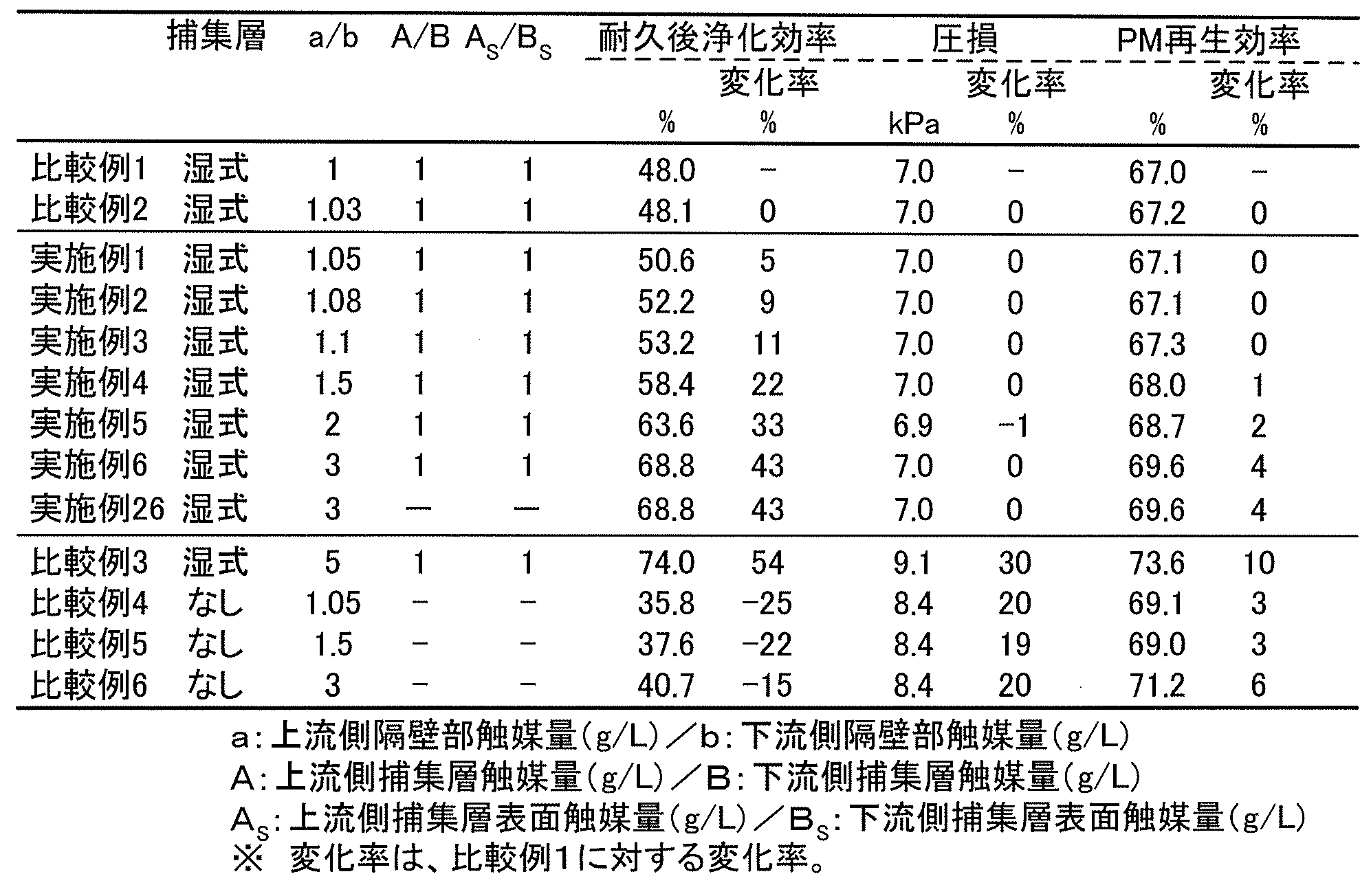
表2には、実施例4,7~15の実験結果を示した。実施例4,7~15は、隔壁部の触媒がa/b=1.5で一定,捕集層表面の触媒がAS/BS=1で一定であり、A/Bを1~8までの間で変化させたものである。この結果より、A/Bを大きくすると、耐久後浄化効率(HC除去効率)がより向上することが分かった。また、1.08≦A/B≦5.00であれば、圧力損失の上昇をより抑制し、耐久後浄化効率をより高めることができることが分かった。このうち、1.50≦A/B≦5.00であれば浄化効率をより高めることができ、2.00≦A/B≦5.00であれば浄化効率をさらに高めることができることが分かった。

表3には、実施例11,16~26の実験結果を示した。実施例11,16~25は、隔壁部の触媒がa/b=1.5で一定、捕集層の触媒がA/B=1.5で一定であり、AS/BSを1~10までの間で変化させたものである。この結果より、AS/BSを大きくすると、耐久後浄化効率(HC除去効率)が向上し、PM再生効率も向上することが分かった。また、1.10≦AS/BS≦8.00であれば、圧力損失の上昇をより抑制し、PM再生効率もより向上することが分かった。このうち、1.50≦AS/BS≦8.00であればPM再生効率がより向上し、3.00≦AS/BS≦8.00であればPM再生効率が更に向上することが分かった。また、捕集層を乾式で形成した実施例26は、捕集層の形成方法以外は同様の工程で作製した実施例22とほぼ同等の結果であったことから、捕集層の形成方法はどのようなものであってもよいと推察された。

本出願は、2010年3月31日に出願された日本国特許出願第2010-81903号を優先権主張の基礎としており、引用によりその内容の全てが本明細書に含まれる。
本発明は、自動車用エンジン、建設機械用及び産業用の定置エンジン並びに燃焼機器等から排出される排ガスを浄化するためのフィルターとして好適に使用することができる。
Claims (5)
- 少なくとも一部に触媒が担持されており一方の端部が開口され且つ他方の端部が目封止され流体の流路となる複数のセルを形成する複数の多孔質の隔壁部と、
前記隔壁部上に形成され前記流体に含まれる固体成分を捕集・除去する層である捕集層と、を備え、
前記セルの上流側の隔壁部である上流側隔壁部の触媒量をa、前記セルの下流側の隔壁部である下流側隔壁部の触媒量をbとすると、1.05≦a/b≦3.00を満たす、ハニカムフィルタ。 - 前記捕集層は少なくとも一部に触媒が担持されており、前記上流側隔壁部に形成された捕集層である上流側捕集層の触媒量をA、前記下流側隔壁部に形成された捕集層である下流側捕集層の触媒量をBとすると、1.08≦A/B≦5.00を満たす、請求項1に記載のハニカムフィルタ。
- 前記捕集層は少なくとも前記流路側の捕集層表面に触媒が担持されており、前記上流側捕集層のセル表面である上流側捕集層表面の触媒量をAS、前記下流側捕集層のセル表面である下流側捕集層表面の触媒量をBSとすると、1.10≦AS/BS≦8.00を満たす、請求項1又は2に記載のハニカムフィルタ。
- 流体に含まれる固体成分を捕集・除去するハニカムフィルタの製造方法であって、
一方の端部が開口され且つ他方の端部が目封止され流体の流路となる複数のセルを形成する複数の多孔質の隔壁部を備えたハニカム構造体に、流体に含まれる固体成分を捕集・除去する層である捕集層を形成する捕集層形成工程と、
前記ハニカム構造体全体を触媒成分に接触させて触媒を形成する全体触媒形成工程と、
前記ハニカム構造体の上流側だけ触媒成分に接触させて触媒を形成する部分触媒形成工程と、
を含むハニカムフィルタの製造方法。 - 流体に含まれる固体成分を捕集・除去するハニカムフィルタの製造方法であって、
一方の端部が開口され且つ他方の端部が目封止された流体の流路となる複数のセルを形成する複数の多孔質の隔壁部を備えたハニカム構造体に、流体に含まれる固体成分を捕集・除去する層である捕集層を形成する捕集層形成工程と、
前記ハニカム構造体の上流側だけ触媒成分に接触させて触媒を形成する上流側触媒形成工程と、
前記ハニカム構造体の下流側だけ前記触媒成分よりも低濃度の触媒成分に接触させて触媒を形成する下流側触媒形成工程と、
を含むハニカムフィルタの製造方法。
Priority Applications (3)
| Application Number | Priority Date | Filing Date | Title |
|---|---|---|---|
| EP11765671.0A EP2556885B1 (en) | 2010-03-31 | 2011-03-30 | Honeycomb filter and method for manufacturing honeycomb filter |
| JP2012509533A JP5775512B2 (ja) | 2010-03-31 | 2011-03-30 | ハニカムフィルタ及びハニカムフィルタの製造方法 |
| US13/292,890 US8420020B2 (en) | 2010-03-31 | 2011-11-09 | Honeycomb filter and method for manufacturing honeycomb filter |
Applications Claiming Priority (2)
| Application Number | Priority Date | Filing Date | Title |
|---|---|---|---|
| JP2010081903 | 2010-03-31 | ||
| JP2010-081903 | 2010-03-31 |
Related Child Applications (1)
| Application Number | Title | Priority Date | Filing Date |
|---|---|---|---|
| US13/292,890 Continuation US8420020B2 (en) | 2010-03-31 | 2011-11-09 | Honeycomb filter and method for manufacturing honeycomb filter |
Publications (1)
| Publication Number | Publication Date |
|---|---|
| WO2011125771A1 true WO2011125771A1 (ja) | 2011-10-13 |
Family
ID=44762712
Family Applications (1)
| Application Number | Title | Priority Date | Filing Date |
|---|---|---|---|
| PCT/JP2011/058081 WO2011125771A1 (ja) | 2010-03-31 | 2011-03-30 | ハニカムフィルタ及びハニカムフィルタの製造方法 |
Country Status (4)
| Country | Link |
|---|---|
| US (1) | US8420020B2 (ja) |
| EP (1) | EP2556885B1 (ja) |
| JP (1) | JP5775512B2 (ja) |
| WO (1) | WO2011125771A1 (ja) |
Cited By (5)
| Publication number | Priority date | Publication date | Assignee | Title |
|---|---|---|---|---|
| EP2609980A1 (en) * | 2011-12-27 | 2013-07-03 | NGK Insulators, Ltd. | Honeycomb filter |
| EP2614872A1 (en) * | 2012-01-10 | 2013-07-17 | NGK Insulators, Ltd. | Honeycomb filter |
| JP2014188466A (ja) * | 2013-03-27 | 2014-10-06 | Ngk Insulators Ltd | 排ガス浄化フィルタ及び排ガス浄化フィルタの製造方法 |
| US10071368B2 (en) | 2015-02-17 | 2018-09-11 | Cataler Corporation | Exhaust gas purification catalyst |
| US10076725B2 (en) | 2015-02-17 | 2018-09-18 | Cataler Corporation | Exhaust gas purification catalyst |
Families Citing this family (6)
| Publication number | Priority date | Publication date | Assignee | Title |
|---|---|---|---|---|
| DE102012220181A1 (de) * | 2012-11-06 | 2014-05-08 | Fraunhofer-Gesellschaft zur Förderung der angewandten Forschung e.V. | Partikelfilter |
| JP6231909B2 (ja) * | 2014-03-14 | 2017-11-15 | 日本碍子株式会社 | 目封止ハニカム構造体及びその製造方法 |
| GB2564333B (en) | 2015-06-28 | 2019-12-04 | Johnson Matthey Plc | Catalytic wall-flow filter having a membrane |
| KR101814459B1 (ko) * | 2016-08-16 | 2018-01-04 | 희성촉매 주식회사 | 알킬 방향족 화합물 제조용 고형 촉매 캐리어로서 필터 구조체 |
| JP7037985B2 (ja) * | 2018-03-30 | 2022-03-17 | 日本碍子株式会社 | ハニカムフィルタ |
| DE112018007753T5 (de) * | 2018-06-20 | 2021-03-04 | Ngk Insulators, Ltd. | Poröser Verbundwerkstoff |
Citations (7)
| Publication number | Priority date | Publication date | Assignee | Title |
|---|---|---|---|---|
| JPH01304022A (ja) | 1988-05-31 | 1989-12-07 | Ibiden Co Ltd | ハニカム状フィルター |
| JPH0633734A (ja) | 1992-07-10 | 1994-02-08 | Ibiden Co Ltd | 排気ガス浄化装置 |
| JP2002177794A (ja) * | 2000-09-29 | 2002-06-25 | Denso Corp | セラミック触媒体およびセラミック担体 |
| JP2004216226A (ja) | 2003-01-10 | 2004-08-05 | Toyota Motor Corp | 排ガス浄化フィルタ触媒 |
| JP2006175386A (ja) * | 2004-12-24 | 2006-07-06 | Cataler Corp | ディーゼルエンジンの排気ガス浄化用のフィルタ触媒及びその製造方法 |
| JP2006189027A (ja) * | 2004-12-06 | 2006-07-20 | Denso Corp | 排ガス浄化フィルタ |
| JP2010081903A (ja) | 2008-10-01 | 2010-04-15 | Yanmar Co Ltd | ロールベーラ |
Family Cites Families (5)
| Publication number | Priority date | Publication date | Assignee | Title |
|---|---|---|---|---|
| JP4393039B2 (ja) * | 2001-07-18 | 2010-01-06 | イビデン株式会社 | 触媒つきフィルタ、その製造方法及び排気ガス浄化システム |
| DE102004040549B4 (de) * | 2004-08-21 | 2017-03-23 | Umicore Ag & Co. Kg | Katalytisch beschichtetes Partikelfilter und seine Verwendung |
| US7740809B2 (en) * | 2006-02-15 | 2010-06-22 | Hitachi Metals, Ltd. | Exhaust gas-cleaning apparatus |
| JP5193437B2 (ja) * | 2006-05-29 | 2013-05-08 | 株式会社キャタラー | 排ガス浄化用触媒 |
| JP5096978B2 (ja) * | 2008-03-27 | 2012-12-12 | 日本碍子株式会社 | ハニカム触媒体 |
-
2011
- 2011-03-30 EP EP11765671.0A patent/EP2556885B1/en active Active
- 2011-03-30 JP JP2012509533A patent/JP5775512B2/ja active Active
- 2011-03-30 WO PCT/JP2011/058081 patent/WO2011125771A1/ja active Application Filing
- 2011-11-09 US US13/292,890 patent/US8420020B2/en active Active
Patent Citations (7)
| Publication number | Priority date | Publication date | Assignee | Title |
|---|---|---|---|---|
| JPH01304022A (ja) | 1988-05-31 | 1989-12-07 | Ibiden Co Ltd | ハニカム状フィルター |
| JPH0633734A (ja) | 1992-07-10 | 1994-02-08 | Ibiden Co Ltd | 排気ガス浄化装置 |
| JP2002177794A (ja) * | 2000-09-29 | 2002-06-25 | Denso Corp | セラミック触媒体およびセラミック担体 |
| JP2004216226A (ja) | 2003-01-10 | 2004-08-05 | Toyota Motor Corp | 排ガス浄化フィルタ触媒 |
| JP2006189027A (ja) * | 2004-12-06 | 2006-07-20 | Denso Corp | 排ガス浄化フィルタ |
| JP2006175386A (ja) * | 2004-12-24 | 2006-07-06 | Cataler Corp | ディーゼルエンジンの排気ガス浄化用のフィルタ触媒及びその製造方法 |
| JP2010081903A (ja) | 2008-10-01 | 2010-04-15 | Yanmar Co Ltd | ロールベーラ |
Cited By (5)
| Publication number | Priority date | Publication date | Assignee | Title |
|---|---|---|---|---|
| EP2609980A1 (en) * | 2011-12-27 | 2013-07-03 | NGK Insulators, Ltd. | Honeycomb filter |
| EP2614872A1 (en) * | 2012-01-10 | 2013-07-17 | NGK Insulators, Ltd. | Honeycomb filter |
| JP2014188466A (ja) * | 2013-03-27 | 2014-10-06 | Ngk Insulators Ltd | 排ガス浄化フィルタ及び排ガス浄化フィルタの製造方法 |
| US10071368B2 (en) | 2015-02-17 | 2018-09-11 | Cataler Corporation | Exhaust gas purification catalyst |
| US10076725B2 (en) | 2015-02-17 | 2018-09-18 | Cataler Corporation | Exhaust gas purification catalyst |
Also Published As
| Publication number | Publication date |
|---|---|
| JP5775512B2 (ja) | 2015-09-09 |
| JPWO2011125771A1 (ja) | 2013-07-08 |
| EP2556885A4 (en) | 2015-07-29 |
| US8420020B2 (en) | 2013-04-16 |
| EP2556885A1 (en) | 2013-02-13 |
| EP2556885B1 (en) | 2021-12-15 |
| US20120058020A1 (en) | 2012-03-08 |
Similar Documents
| Publication | Publication Date | Title |
|---|---|---|
| JP5775512B2 (ja) | ハニカムフィルタ及びハニカムフィルタの製造方法 | |
| JP5604346B2 (ja) | ハニカムフィルタ | |
| JP5764120B2 (ja) | ハニカムフィルタ | |
| JP5291966B2 (ja) | 触媒担持フィルタ | |
| JP5635076B2 (ja) | ハニカムフィルタ | |
| JP5208897B2 (ja) | ハニカムフィルタ | |
| JP5634984B2 (ja) | ハニカムフィルタ及びその製造方法 | |
| JP5634983B2 (ja) | ハニカムフィルタ及びその製造方法 | |
| JP5666562B2 (ja) | ハニカムフィルタ | |
| JP2009220029A (ja) | 触媒担持フィルタ | |
| JP2009226375A (ja) | 触媒担持フィルタ | |
| JP5031647B2 (ja) | ハニカム構造体の製造方法 | |
| JP5714568B2 (ja) | ハニカムフィルタ | |
| JP5714567B2 (ja) | ハニカムフィルタ | |
| JP5714372B2 (ja) | ハニカムフィルタの製造方法 | |
| JP5954994B2 (ja) | ハニカムフィルタ | |
| JP5771190B2 (ja) | ハニカムフィルタ | |
| EP2614872B1 (en) | Honeycomb filter | |
| JP5785870B2 (ja) | ハニカムフィルタ | |
| JP5869887B2 (ja) | ハニカムフィルタ |
Legal Events
| Date | Code | Title | Description |
|---|---|---|---|
| WWE | Wipo information: entry into national phase |
Ref document number: 2012509533 Country of ref document: JP |
|
| WWE | Wipo information: entry into national phase |
Ref document number: 2011765671 Country of ref document: EP |
|
| 121 | Ep: the epo has been informed by wipo that ep was designated in this application |
Ref document number: 11765671 Country of ref document: EP Kind code of ref document: A1 |
|
| NENP | Non-entry into the national phase |
Ref country code: DE |