WO2011125370A1 - 観察装置及び観察方法 - Google Patents
観察装置及び観察方法 Download PDFInfo
- Publication number
- WO2011125370A1 WO2011125370A1 PCT/JP2011/052543 JP2011052543W WO2011125370A1 WO 2011125370 A1 WO2011125370 A1 WO 2011125370A1 JP 2011052543 W JP2011052543 W JP 2011052543W WO 2011125370 A1 WO2011125370 A1 WO 2011125370A1
- Authority
- WO
- WIPO (PCT)
- Prior art keywords
- pupil function
- light
- image
- observation
- incoming light
- Prior art date
- Legal status (The legal status is an assumption and is not a legal conclusion. Google has not performed a legal analysis and makes no representation as to the accuracy of the status listed.)
- Ceased
Links
Images














Classifications
-
- G—PHYSICS
- G02—OPTICS
- G02B—OPTICAL ELEMENTS, SYSTEMS OR APPARATUS
- G02B21/00—Microscopes
- G02B21/0004—Microscopes specially adapted for specific applications
- G02B21/002—Scanning microscopes
- G02B21/0024—Confocal scanning microscopes (CSOMs) or confocal "macroscopes"; Accessories which are not restricted to use with CSOMs, e.g. sample holders
- G02B21/008—Details of detection or image processing, including general computer control
-
- G—PHYSICS
- G02—OPTICS
- G02B—OPTICAL ELEMENTS, SYSTEMS OR APPARATUS
- G02B21/00—Microscopes
- G02B21/36—Microscopes arranged for photographic purposes or projection purposes or digital imaging or video purposes including associated control and data processing arrangements
- G02B21/365—Control or image processing arrangements for digital or video microscopes
Definitions
- the present invention relates to an observation apparatus and an observation method for observing an observation object based on incoming light coming from the observation object.
- the wavelength of the fluorescence emitted from the object to be observed is different from the wavelength of the excitation light, only the fluorescence can be extracted with a filter or the like to obtain a two-dimensional tomographic image.
- a scanning fluorescence microscope there is a confocal optical microscope that acquires a two-dimensional tomographic image.
- the object to be observed is laser-scanned along the two-dimensional tomographic plane to obtain point light coming from the object to be observed. Since a two-dimensional tomographic image composed only of images in focus can be acquired, an image with less blur can be generated and the object to be observed can be observed (Patent Documents 1 and 2).
- the object to be observed is laser-scanned along the two-dimensional tomographic plane to acquire point light coming from the object to be observed. It is necessary to strictly synchronize the spotlight acquisition timing. As a result, the observation apparatus requires expensive and highly accurate synchronization means. Furthermore, since the object to be observed is laser-scanned along the two-dimensional tomographic plane, the time for acquiring the two-dimensional tomographic image of the object to be observed is limited by the scanning time.
- the present invention has been made in view of the above problems, and an object of the present invention is to obtain a clear image in which blur is eliminated from two-dimensional tomographic image information obtained using incoming light arriving from an object to be observed.
- An object of the present invention is to provide an observation apparatus and an observation method.
- an observation apparatus is an observation apparatus that observes the object to be observed based on incoming light coming from the object to be observed.
- a conversion unit that converts the incoming light into a second converted light by a second pupil function, the first converted light, and the second converted light, and relates to the object to be observed.
- An image information generation unit that generates image information.
- Image information related to the observation object is generated.
- the converted light converted with different pupil functions has different intensity distributions.
- different intensity distributions are overlapped or the difference between different intensity distributions is taken, the difference between the peak intensity and other intensities becomes clearer, and the spread of the intensity distribution of incoming light coming from the observed object is suppressed. I can do it.
- the observation apparatus further includes a pupil function changing unit that changes at least one of the first pupil function and the second pupil function. For example, even when image information that is not suitable for observation is obtained by combining the first pupil function and the second pupil function, at least one of the first pupil function and the second pupil function is appropriately changed. Then, an image having a desired resolution with less blur can be obtained.
- the conversion unit includes a first conversion unit that converts the incoming light with the first pupil function, and a second that converts the incoming light with the second pupil function. Including a conversion unit. That is, the conversion unit includes separate first conversion unit and second conversion unit. As a result, the incoming light can be simultaneously converted into the first converted light and the second converted light, and image information with less blur can be generated quickly and reliably.
- the conversion unit includes a reflective member or a transmissive member.
- the reflection type member and the transmission type member can be easily obtained at low cost as ready-made products. Therefore, the incoming light can be converted into the first converted light and the second converted light, respectively, with an inexpensive configuration without requiring a special configuration as the conversion unit.
- the observation apparatus further includes a focal position changing unit that changes the focal position of the incoming light.
- the change of the focal position of the incoming light can be realized by changing the optical path length to the focal point of the incoming light, whereby the spread of the intensity distribution of the incoming light coming from the object to be observed can be changed.
- a focal position changing unit that changes the focal position of the incoming light.
- the first pupil function and the second pupil function are two-dimensional donut-shaped functions having an inner ring and an outer ring, and the first conversion unit and the first pupil function
- the 2 conversion unit causes a region surrounded by each inner ring and outer ring to function as a non-shielding region of the first pupil function and the second pupil function.
- the conversion unit can block the incoming light that has arrived outside the donut-shaped outer ring, and the influence of spherical aberration caused by the optical system of the observation apparatus is reduced, improving the optical axis resolution. I can do it.
- the conversion unit can block incoming light that has arrived in the inner area of the donut-shaped inner ring, and can eliminate the influence of noisy light that has arrived in the inner area of the donut-shaped inner ring. it can. As a result, a clearer image can be obtained.
- the value of the ratio between the diameter of the inner ring and the diameter of the outer ring is 1/6 to 4/5. If the value of the ratio between the inner ring diameter and the outer ring diameter is within this range, the spread of the intensity distribution of the incoming light coming from the object can be reliably suppressed. As a result, it is possible to obtain a clear image in which blur is eliminated from the two-dimensional tomographic image information obtained using the incoming light coming from the object to be observed.
- an observation method is an observation method for observing the object to be observed based on incoming light coming from the object to be observed, and the first method uses the first pupil function for the incoming light.
- An image relating to the object to be observed based on the conversion step of converting into the converted light and converting the incoming light into the second converted light with a second pupil function, the first converted light, and the second converted light.
- an image information generation step for generating information.
- the same operational effects as the above-described observation apparatus of the present invention are exhibited. That is, according to the observation method of the present invention, based on the first converted light obtained by converting the incoming light arriving from the observation object by the first pupil function and the second converted light converted by the second pupil function, Image information related to the observation object is generated.
- the converted light converted with different pupil functions has different intensity distributions. When different intensity distributions are overlapped or the difference between different intensity distributions is taken, the difference between the peak intensity and other intensities becomes clearer, and the spread of the intensity distribution of incoming light coming from the observed object is suppressed. I can do it. As a result, it is possible to obtain a clear image in which blur is eliminated from the two-dimensional tomographic image information obtained using the incoming light coming from the object to be observed.
- the observation method of the present invention further includes a pupil function changing step of changing at least one of the first pupil function and the second pupil function. For example, even when image information that is not suitable for observation is obtained by combining the first pupil function and the second pupil function, at least one of the first pupil function and the second pupil function is appropriately changed. Then, an image having a desired resolution with less blur can be obtained.
- the conversion step includes a first conversion step of converting the incoming light with the first pupil function, and a second of converting the incoming light with the second pupil function. Conversion step. That is, as the conversion step, separate first conversion step and second conversion step are executed. As a result, the incoming light can be simultaneously converted into the first converted light and the second converted light, and image information with less blur can be generated quickly and reliably.
- the observation method of the present invention further includes a focal position changing step of changing the focal position of the incoming light by the conversion step.
- the change of the focal position of the incoming light can be realized by changing the optical path length to the focal point of the incoming light, and thereby the spread of the intensity distribution of the incoming light coming from the object to be observed can be changed.
- an image having a desired resolution with less blur can be obtained by changing the focal position of the incoming light. .
- an observation apparatus is an observation apparatus that observes the object to be observed based on the incoming light coming from the object to be observed, and has an intensity of the incoming light of at least 1
- a conversion unit that converts the incoming light into converted light by modulating with two pupil functions
- an image information generation unit that generates image information relating to the object to be observed based on the converted light, the at least one pupil
- the function has a shielding area and a non-shielding area arranged around the shielding area.
- an observation method is an observation method for observing the object to be observed based on incoming light coming from the object to be observed, wherein the intensity of the incoming light is set to at least one. Including a conversion step of converting the incoming light into converted light by modulating with a pupil function, and an image information generation step of generating image information relating to the object to be observed based on the converted light.
- the at least one pupil function has a shielding area and a non-shielding area arranged around the shielding area.
- the observation apparatus and the observation method of the present invention it is possible to shield incoming light that has arrived at a shielding area inside the non-shielding area, thereby eliminating the influence of noisy light arriving at the shielding area. . As a result, it is possible to obtain a clear image in which blur is eliminated from the two-dimensional tomographic image information obtained using the incoming light coming from the object to be observed.
- FIG. 1 It is a schematic diagram of the observation apparatus which concerns on Embodiment 1 of this invention.
- the observation device in which all pixels absorb light in the second conversion unit and all pixels reflect light in the first conversion unit, it is a diagram showing a point image distribution of fluorescent beads, (a) It is a figure which shows the point image distribution of a XZ plane, (b) And (c) is a graph which shows the point image distribution of a X-axis direction and a Z-axis direction, respectively.
- FIG. 6 is a diagram showing point distributions of fluorescent beads in an observation apparatus in which all pixels absorb light in the second conversion unit and various donut-shaped pupil functions are given to the first conversion unit;
- a pupil function a point image distribution in the XZ plane, a graph showing the point image distribution in the X-axis direction, and a graph showing the point image distribution in the Z-axis direction are shown.
- It is a conceptual diagram of the image which an image information generation part acquires.
- FIG. 7 is a diagram showing a point image distribution of fluorescent beads in an observation device given a function
- (a) is a diagram showing a point image distribution on an XZ plane
- (b) and (c) are X axis axes, respectively. It is a graph which shows the point image distribution of a direction and a Z-axis direction.
- FIG. 6 is a diagram showing a point image distribution of fluorescent beads after the focal length of incoming light is changed by movement of the second conversion unit with respect to the observation device obtained as a result shown in FIG.
- FIG. 6 is a diagram showing point image distributions on the ⁇ Z plane
- (b) and (c) are graphs showing point image distributions in the X-axis direction and the Z-axis direction, respectively.
- a first doughnut-shaped pupil function having an outer ring diameter of 1040 ⁇ m and an inner ring diameter of 832 ⁇ m is provided to the first converter
- a donut-shaped second pupil having an outer ring diameter of 624 ⁇ m and an inner ring diameter of 208 ⁇ m is provided to the second converter.
- FIG. 7 is a diagram showing a point image distribution of fluorescent beads in an observation device given a function
- (a) is a diagram showing a point image distribution on an XZ plane
- (b) and (c) are X axis axes, respectively. It is a graph which shows the point image distribution of a direction and a Z-axis direction.
- (A) is a figure which shows a 1st pupil function and its point image distribution
- (b) is a figure which shows a 2nd pupil function and its point image distribution
- (c) is a 1st pupil function and a 2nd pupil. It is a figure which shows the difference with a function, and the difference of these point image distributions.
- (A) is a schematic diagram showing that light is not shielded, and (b) is a diagram showing a point image distribution on the XZ plane.
- (A) is a figure which shows a 1st pupil function
- (b) is a figure which shows the point image distribution of a XZ plane.
- (A) is a figure which shows a 2nd pupil function
- (b) is a figure which shows the point image distribution of a XZ plane.
- (A) is a graph which shows the point image distribution of the X-axis direction in the case shown to FIG.9 (b), FIG.10 (b), and FIG.11 (b),
- (b) is FIG.9 (b).
- FIG. 12 is a graph showing a point image distribution in the Z-axis direction in the case shown in FIGS. 10 (b) and 11 (b).
- (A) is a figure which shows the difference of the point image distribution shown to FIG.10 (b) and FIG.11 (b), (b) and (c) are the X-axis direction and Z-axis direction of (a), respectively. It is a graph which shows point image distribution.
- (A) is a figure which shows the point image distribution after changing the focal distance of incoming light with respect to the observation apparatus with which the result shown to Fig.13 (a) was obtained, (b) and (c). 4 is a graph showing point image distributions in the X-axis direction and the Z-axis direction of FIG.
- (A) is a diagram showing a point image distribution on the XZ plane
- (b) to (d) are diagrams showing point image distributions obtained by digital image processing.
- (A) is a figure which shows the difference of the point image distribution shown to Fig.15 (a) and FIG.15 (b), (b) and (c) are the X-axis direction and Z-axis direction of (a), respectively. It is a graph which shows point image distribution.
- (A) is a figure which shows the difference of the point image distribution shown to Fig.15 (a) and FIG.15 (d), (b) and (c) are the X-axis direction and Z-axis direction of (a), respectively. It is a graph which shows point image distribution.
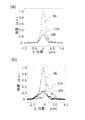
- FIG. 20 is a graph showing a fluorescence intensity distribution in a cross section of a portion indicated by a dotted line in FIG.
- (a) is a graph showing a fluorescence intensity distribution of an image observed by the observation apparatus 100
- (b) is a conventional fluorescence microscope. It is a graph which shows the fluorescence intensity distribution of the image observed by.
- (A) is a figure which shows the image observed with the conventional fluorescence microscope
- (b) is a figure which shows the image observed with the observation apparatus 100 in Example 2.
- FIG. It is a graph which shows the fluorescence intensity distribution in the cross section of the location shown by the dotted line in Fig.22 (a) and FIG.22 (b).
- (A) is a figure which shows the image obtained by digital image processing
- (b) is an enlarged view of the area
- (c) was shown with the broken line of (b).
- (A) is a figure which shows the image obtained by digital image processing
- (b) is an enlarged view of the area
- (c) was shown with the broken line of (b).
- (A) is a figure which shows the image obtained by digital image processing
- (b) is an enlarged view of the area
- (c) was shown with the broken line of (b).
- (A) is a figure which shows the image observed with the observation apparatus 100 in Example 3
- (b) is an enlarged view of the area
- (c) is a figure of (b).
- (A)-(g) is a figure which shows the image observed with the observation apparatus 100 in Example 4 in each different time. It is a schematic diagram which shows the time change of the fluorescence intensity distribution from the cadherin observed with the observation apparatus 100 in Example 4.
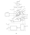
- FIG. 1 is a schematic diagram of an observation apparatus 100 according to Embodiment 1 of the present invention.
- the observation apparatus 100 observes the observation object 1 based on the incoming light 2 coming from the observation object 1.
- the observation apparatus 100 includes an optical system 102, a conversion unit 104 that converts incoming light 2 into first converted light using a first pupil function, and converts incoming light into second converted light using a second pupil function, and image information.
- a generation unit 106, a pupil function changing unit 108, and a focal position changing unit 110 are provided.
- the pupil function changing unit 108 and the focus position changing unit 110 may be referred to as the function changing unit 108 and the position changing unit 110, respectively.
- the optical system 102 is provided after the imaging surface of the fluorescence microscope 3.
- the optical system 102 includes a slit 102a for limiting the field of view disposed on the imaging surface, a first relay lens 102b, a second relay lens 102c for relaying a real image on the imaging surface to the image information generation unit 106, and
- the image transmitted by the first mirror 102d, the first polarization beam splitter 102e for dividing the incoming light 2 into two for each polarization component, and the first relay lens 102b and the second relay lens 102c are sent to the image information generation unit 106.
- the second polarization beam splitter 102g for dividing the polarization image into two parts and the divided image are combined again.
- the optical system 102 is not limited to the configuration illustrated in FIG. 1 as long as the incoming light 2 can be guided to the conversion unit 104 and the converted light can be guided to the image information generation unit 106.
- the combination and arrangement of the relay lens, mirror, and polarization beam splitter are arbitrary.
- a relay optical system including two lenses 102b and 102c and a relay optical system including 102f and 102i or 102j are used in order to transmit a real image acquired by the fluorescence microscope 3 to the image information generation unit 106.
- a relay optical system including two lenses 102b and 102c and a relay optical system including 102f and 102i or 102j are used. And through.
- a relay optical system including two lenses is used.
- an optical system using a single lens can be used.
- the lens 102b is disposed above the first polarizing beam splitter 102e.
- the conversion unit 104 includes a first conversion unit 104a that converts the incoming light 2 with a first pupil function, and a second conversion unit 104b that converts the incoming light 2 with a second pupil function.
- the pupil function is a function having light phase and intensity parameters. Note that when the incoming light 2 is fluorescent, the light is incoherent, so the pupil function is a function having a parameter of light intensity.
- the pupil function is represented by the reflectance at the light receiving surface of the conversion unit.
- the converted light converted with different pupil functions has different intensity distributions. When different intensity distributions are overlapped or the difference between the different intensity distributions is taken, the difference between the peak intensity and the other intensity becomes clearer.
- the 1st conversion part 104a and the 2nd conversion part 104b are arrange
- the first conversion unit 104a and the second conversion unit 104b include, for example, a reflective member.
- a reflective liquid crystal mirror array is used as the reflective member.
- the image information generation unit 106 uses the first converted light obtained by converting the incoming light 2 by the first pupil function and the second converted light obtained by converting the incoming light by the second pupil function to obtain image information related to the object 1 to be observed. Is generated.
- the image information generation unit 106 processes the acquired image information, and an image information acquisition unit 106a that acquires image information related to the observation object 1 based on the intensity distribution of the first converted light and the intensity distribution of the second converted light. And an image information processing unit 106b.
- the function changing unit 108 changes at least one of the first pupil function given to the first converting unit 104a and the second pupil function given to the second converting unit 104b.
- the function change unit 108 outputs a signal so that the pupil function is changed to at least one of the first conversion unit 104a and the second conversion unit 104b.
- the function changing unit 108 applies a voltage to the first conversion unit 104a and the second conversion unit 104b.
- the pupil function can be changed by controlling the tilt of the liquid crystal molecules.
- the position changing unit 110 changes the focal position of the incoming light 2.
- the position changing unit 110 can move the focal position of the incoming light 2 in the optical axis direction.
- the position changing unit 110 can move the fifth relay lens 102m in the optical axis direction.
- the incoming light 2 that has passed through the slit 102a is decomposed into two polarization components of a longitudinal wave and a transverse wave by the first polarization beam splitter 102e. Longitudinal light is applied to the first converter 104a, and transverse light is applied to the second converter 104b.
- the longitudinal wave light applied to the first conversion unit 104a is two-dimensionally phase-modulated to the polarization component and reflected as first converted light converted by the first pupil function applied to the first conversion unit 104a. To do.
- the transverse wave light irradiated to the second conversion unit 104b is reflected as second converted light that is two-dimensionally given phase modulation to the polarization component and converted by the second pupil function applied to the second conversion unit 104b. .
- the first conversion unit 104a and the second conversion unit 104b are arranged at the position of the optical pupil, the first conversion unit 104a and the second conversion unit 104b are arranged by the two-dimensional distribution of the parts phase-modulated by the first conversion unit 104a and the second conversion unit 104b.
- the pupil function of the optical system composed of the first relay lens 102b and the second relay lens 102c is determined.
- the image acquired by the fluorescence microscope 3 passes through the second relay lens 102c, forms an image once, and is further transmitted to the image information generation unit 106 by the subsequent optical system, and is received by the light receiving surface of the image information acquisition unit 106a. Imaged.
- the light that has passed through the third relay lens 102f is again divided into two by the second polarization beam splitter 102g according to the polarization component.
- the two lights pass through the fourth relay lens 102k and the fifth relay lens 102m, are combined by the third polarization beam splitter 102h, and are transmitted to the image information acquisition unit 106a.
- the image information acquisition unit 106a is, for example, a CCD camera.
- the first conversion unit 104a and the second conversion unit 104b a reflective liquid crystal mirror array having a pixel size of 10.4 ⁇ m, a number of pixels of 1400 horizontal, and 1050 vertical is used.
- an epi-illumination fluorescence microscope was used as the fluorescence microscope 3
- an objective lens having a numerical aperture of 1.45 and a magnification of 60 times was selected as the objective lens.
- the magnification of the relay optical composed of the first relay lens 102b and the second relay lens 102c is 5 times.
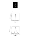
- FIG. 2 is a diagram showing a point image distribution of fluorescent beads in the observation apparatus 100 in which all pixels absorb light in the second conversion unit 104b and all pixels reflect light in the first conversion unit 104a. It is.
- the first conversion unit 104a is used, and the optical path including the second conversion unit 104b is not used. Under the above conditions, the phase was shifted by ⁇ / 4 in all the microarrays of the first conversion unit 104a, and fluorescent beads having a diameter of 100 nm were measured.
- FIG. 2 (a) shows the point image distribution of fluorescent beads in the XZ plane.
- the horizontal axis indicates the horizontal axis (X axis), and the vertical axis indicates the optical axis (Z axis).
- the first conversion unit 104a is unshielded at all positions on the light receiving surface, which means that each pixel reflects light on the light receiving surface of the first conversion unit 104a.
- FIG. 2B shows a point image distribution in the X-axis direction.
- the horizontal axis indicates the X-axis position, and the vertical axis indicates the light intensity.
- the point image distribution in the X-axis direction indicates the horizontal resolution of the microscope. Point images emitted from points smaller than the diffraction limit approximately follow a Gaussian distribution.
- the resolution of the microscope is defined by the half width of the point image distribution shown in FIG.
- the horizontal resolution was 225 nm.
- FIG. 2C shows a point image distribution in the Z-axis direction.
- the horizontal axis indicates the Z-axis position, and the vertical axis indicates the light intensity.
- the point image distribution in the Z-axis direction indicates the optical axis resolution of the microscope.
- the point image distribution emitted from a point smaller than the diffraction limit theoretically follows a Gaussian distribution even in the Z-axis direction.
- the distribution deviates from the Gaussian distribution due to the spherical aberration of the optical system forming the image.
- Spherical aberration causes a reduction in the optical axis resolution of the microscope.
- the optical axis resolution was 1472 nm.
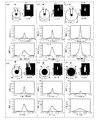
- FIG. 3 is a diagram showing a point image distribution of fluorescent beads in the observation apparatus 100 in which all pixels absorb light in the second conversion unit 104b and various donut-shaped pupil functions are given to the first conversion unit 104a. is there.
- a region surrounded by the donut-shaped inner ring and outer ring functions as a non-shielding region for the pupil function.
- the inner ring and the outer ring have a substantially circular shape, and the diameter of the circumference corresponding to the outer ring is larger than the diameter of the circumference corresponding to the inner ring.
- the pupil function can be changed by changing the phase of the area surrounded by the inner ring and the outer ring, or changing the transmittance and the reflectance of the surrounded area.
- the degree of phase change in the enclosed region is ⁇ / 4.
- a pupil indicates the shape of a given pupil function
- PSF Point Spread Function
- the horizontal axis indicates the X-axis position
- the vertical axis indicates the light intensity
- the horizontal axis indicates the Z axis position
- the vertical axis indicates the light intensity.
- FIG. 3A shows a point image distribution of fluorescent beads in the observation apparatus 100 in which the first conversion unit 104a is provided with a donut-shaped pupil function having an inner ring diameter of 208 ⁇ m and an outer ring diameter of 832 ⁇ m.
- FIG. 3B shows a point image distribution of fluorescent beads in the observation device 100 in which the first conversion unit 104a is provided with a donut-shaped pupil function having an inner ring diameter of 208 ⁇ m and an outer ring diameter of 1040 ⁇ m.
- FIG. 3C shows a point image distribution of fluorescent beads in the observation device 100 in which the first conversion unit 104a is provided with a donut-shaped pupil function having an inner ring diameter of 208 ⁇ m and an outer ring diameter of 1248 ⁇ m.
- FIG. 3A shows a point image distribution of fluorescent beads in the observation apparatus 100 in which the first conversion unit 104a is provided with a donut-shaped pupil function having an inner ring diameter of 208 ⁇ m and an outer ring diameter of 832
- FIG. 3D shows a point image distribution of fluorescent beads in the observation device 100 in which the first conversion unit 104a is provided with a donut-shaped pupil function having an inner ring diameter of 416 ⁇ m and an outer ring diameter of 1040 ⁇ m.
- FIG. 3E shows a point image distribution of fluorescent beads in the observation device 100 in which a donut-shaped pupil function having an inner ring diameter of 624 ⁇ m and an outer ring diameter of 1040 ⁇ m is given to the first converter 104a.
- FIG. 3F shows the point image distribution of fluorescent beads in the observation device 100 in which the first conversion unit 104a is provided with a donut-shaped pupil function having an inner ring diameter of 832 ⁇ m and an outer ring diameter of 1040 ⁇ m.
- the value of the ratio between the diameter of the doughnut-shaped inner ring and the diameter of the outer ring is in the range of 1/6 to 4/5.
- the optical axis resolution is improved by providing the conversion unit 104 with a donut-shaped pupil function. It is considered that the effect of spherical aberration is reduced by the donut-shaped pupil function.
- the donut-shaped pupil function light is shielded at a portion (center portion) defined inside the inner ring, and light is not substantially shielded at a portion (surrounding portion) defined by a region between the outer ring and the inner ring.
- the reflected light intensity of the portion defined inside the inner ring is substantially zero, and the reflected light intensity of the portion defined in the region between the outer ring and the inner ring is approximately 1 (normalized by the maximum value). )).
- wheel is zero.
- the incoming light 2 is converted into converted light by the conversion unit 104 modulating the intensity of the incoming light 2.
- the first and second conversion units 104a and 104b an arbitrary pupil function can be realized by appropriately adjusting the reflectance of each pixel on the light receiving surface.
- the point image distribution corresponds to the power spectrum of the Fourier transform of the pupil function
- the portion corresponding to the inner side of the inner ring in the above-described donut-shaped pupil function corresponds to the low frequency component of the point image distribution. Yes. Therefore, the resolution can be improved by removing the light in this portion.
- the horizontal resolution was 233 nm and the optical axis resolution was 942 nm.
- improving the optical axis resolution indicates the same effect as that of the confocal microscope, and thus means that a fluorescence tomographic image can be acquired.
- FIG. 4 is a conceptual diagram of an image acquired by the image information generation unit 106.
- Different pupil functions may be given to each of the first conversion unit 104a and the second conversion unit 104b. Therefore, the image information generation unit 106 can acquire an image based on the converted light converted by two different pupil functions (first pupil function and second pupil function) as one image.
- images provided with two different pupil functions are arranged in parallel on the top and bottom or the left and right of the image, and can be acquired as one image. .
- Image F 1 denotes an image based on the converted light is converted by the first conversion unit 104a
- the image F 2 shows an image based on the converted light is converted by the second conversion unit 104b.
- image F 1, F 2 of the XY plane in FIG. 4 shows image F 1, F 2 of the XY plane in FIG. 4, the image F 1, F 2 is X-axis, the optical axis as well as Y-axis direction (Z-axis) also have a direction component Yes.
- the images F 1 and F 2 having components in the XYZ directions are acquired by moving the objective lens of the fluorescence microscope 3 in the optical axis (Z axis) direction.
- Image information processing unit 106b adds the image information acquisition unit images F obtained by 106a 1 and the image F 2, may be subtracted or multiplied.
- a donut-shaped pupil function having an outer diameter of 1040 ⁇ m and an inner diameter of 208 ⁇ m is given to the first converter 104a
- a donut-shaped pupil function having an outer diameter of 1040 ⁇ m and an inner diameter of 832 ⁇ m is given to the second converter 104b.
- the point image distribution in the image F 1 is the distribution shown in FIG. 3B
- the point image distribution in the image F 2 is the distribution shown in FIG.
- Image information processing unit 106b divides one image obtained from the image information acquisition unit 106a in the image F 1 and image F 2, adds the image F 1 and image F 2, subtracted or multiplied, new A single image can be created.
- the unit of the result of addition or subtraction indicates the light intensity, but the unit of the result of multiplication does not indicate the light intensity. However, the result of multiplication corresponds to the light intensity. For this reason, even when the first pupil function and the second pupil function are equal, the result of multiplication can be used.
- the optical path length of the optical system passing through the second conversion unit 104b moves the second conversion unit 104b by minute changes, by multiplying the image F 1 and image F 2, to improve the resolution Can do.
- an image related to the object to be observed 1 based on the first converted light obtained by converting the incoming light 2 using the first pupil function and the second converted light converted using the second pupil function.
- the converted light reflected by different pupil functions has different intensity distributions. When different intensity distributions are overlapped or the difference between different intensity distributions is taken, the difference between the peak intensity and other intensities becomes clearer, and the spread of the intensity distribution of incoming light coming from the observed object is suppressed. I can do it. As a result, it is possible to obtain a clear image in which blur is eliminated from the two-dimensional tomographic image information obtained using the incoming light coming from the object to be observed.
- the conversion unit 104 includes a first conversion unit 104a and a second conversion unit 104b. That is, the conversion unit 104 includes separate first conversion unit 104a and second conversion unit 104b. As a result, the incoming light 2 can be converted into the first converted light and the second converted light at the same time, and image information with less blur can be generated quickly and reliably.
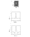
- FIG. 5 gives the first converter 104a a donut-shaped first pupil function (see FIG. 3B) having an outer ring diameter of 1040 ⁇ m and an inner ring diameter of 208 ⁇ m, and the outer diameter of the outer ring is given to the second converter 104b.
- Image information was generated based on the intensity difference (subtraction) between the first converted light converted by the first pupil function and the second converted light converted by the second pupil function.
- FIG. 5A shows a point image distribution in the XZ plane.
- the horizontal axis indicates the horizontal axis
- the vertical axis indicates the optical axis.
- FIG. 5B shows a point image distribution in the X-axis direction.
- the horizontal axis indicates the X-axis position
- the vertical axis indicates the light intensity.
- FIG. 5C shows a point image distribution in the Z-axis direction.
- the horizontal axis indicates the Z-axis position, and the vertical axis indicates the light intensity.
- the distribution function has a Laplacian filter-like shape.
- the Laplacian filter has an effect of making an image edge (boundary) stand out in image processing.
- FIG. 5C shows that the edge stands out in the Z-axis direction although it is asymmetrical in the vertical direction along the Z-axis.
- the first pupil function and the second pupil function are donut-shaped functions having an inner ring and an outer ring, and the first conversion unit 104a and the second conversion unit 104b have their respective inner and outer rings.
- the region surrounded by is made to function as a non-shielding region of the first pupil function and the second pupil function. Accordingly, it is possible to prevent reflection of the incoming light 2 arriving at a region outside the donut-shaped outer ring in the conversion unit 104. As a result, the influence of spherical aberration due to the optical system of the observation apparatus 100 is reduced, and the optical axis resolution can be improved.
- reflection of incoming light that has arrived in a region inside the donut-shaped inner ring of the conversion unit 104 can be prevented. Therefore, it is possible to eliminate the influence of noisy light that has arrived in the region inside the donut-shaped inner ring. As a result, a clearer image can be obtained.
- FIG. 6 is a diagram showing the point image distribution of the fluorescent beads after the focal length of the incoming light 2 is changed by the movement of the second conversion unit 104b.
- a first donut-shaped pupil function (see FIG. 3B) having an outer ring diameter of 1040 ⁇ m and an inner ring diameter of 208 ⁇ m is given to the first converter 104a, and an outer ring diameter of 1040 ⁇ m is given to the second converter 104b.
- a donut-shaped second pupil function (see FIG. 3F) having a diameter of 832 ⁇ m is given.
- the focal length of the light was changed by 200 nm by moving the second conversion unit 104b to slightly change the optical path length of the optical system passing through the second conversion unit 104b.
- the position changing unit 110 can also change the focal length by moving the fifth relay lens 102m in the optical axis direction. After moving the focal length, image information is generated based on a difference (subtraction) in intensity between the first converted light converted by the first pupil function and the second converted light converted by the second pupil function.
- FIG. 6A shows the point image distribution in the XZ plane.
- the horizontal axis indicates the horizontal axis, and the vertical axis indicates the optical axis.
- FIG. 6B shows a point image distribution in the X-axis direction.
- the horizontal axis indicates the X-axis position, and the vertical axis indicates the light intensity.
- FIG. 6C shows a point image distribution in the Z-axis direction.
- the horizontal axis indicates the Z-axis position, and the vertical axis indicates the light intensity. Comparing FIG. 6C with FIG. 5C, it is vertically symmetrical along the Z axis, and shows that the edge is more prominent in the Z axis direction.
- the horizontal resolution is 222 nm and the optical axis resolution is 702 nm.
- the optical axis resolution in FIG. 6 was improved about twice as compared with the example described with reference to FIG. Further, the horizontal resolution was equivalent.
- the function changing unit 109 can change at least one of the first pupil function and the second pupil function. For example, even when image information that is not suitable for observation is obtained by combining the first pupil function and the second pupil function, at least one of the first pupil function and the second pupil function is appropriately changed. Then, an image having a desired resolution with less blur can be obtained.
- the focal position of the incoming light 2 can be changed by the position changing unit 110.
- Changing the focal position of the incoming light 2 corresponds to changing the optical path length to the focal point of the incoming light 2. Therefore, the spread of the intensity distribution of the incoming light 2 can be changed. As a result, even when it is difficult to obtain a sufficient resolution only by combining the first pupil function and the second pupil function, an image having a desired resolution with less blur can be obtained by changing the focal position of the incoming light. .
- observation device 100 is not limited to moving the fifth relay lens 102m in the optical axis direction by the position changing unit 110 as long as the focal position of the incoming light 2 can be changed.
- the focal position of the incoming light 2 can be changed by moving the first conversion unit 104a or the second conversion unit 104b by the position changing unit 110.
- FIG. 7 shows a first doughnut-shaped pupil function having an outer ring diameter of 1040 ⁇ m and an inner ring diameter of 832 ⁇ m for the first converter 104a, and an outer ring diameter of 624 ⁇ m and an inner ring diameter of 208 ⁇ m for the second converter 104b. It is a figure which shows the point image distribution of a fluorescent bead in the observation apparatus 100 which gave the donut-shaped 2nd pupil function.
- the focal length of the second converted light by the second conversion unit 104b was changed to slightly change the optical path length of the optical system.
- the position changing unit 110 moves the fifth relay lens 102m in the optical axis direction, thereby changing the focal length of the second converted light by the second converting unit 104b. After moving the focal length, image information is generated based on a difference (subtraction) in intensity between the first converted light converted by the first pupil function and the second converted light converted by the second pupil function.
- FIG. 7A shows the point image distribution in the XZ plane.
- the horizontal axis indicates the horizontal axis, and the vertical axis indicates the optical axis.
- FIG. 7B shows a point image distribution in the X-axis direction.
- the horizontal axis indicates the X-axis position, and the vertical axis indicates the light intensity.
- FIG. 7C shows a point image distribution in the Z-axis direction.
- the horizontal axis indicates the Z-axis position, and the vertical axis indicates the light intensity.
- the function change unit 108 can change at least one of the first pupil function and the second pupil function by applying a voltage to the first conversion unit 104a and the second conversion unit 104b, for example. That is, the point image distribution in the images F 1 and F 2 can be changed, and the focal lengths of the first and second converted lights forming the images F 1 and F 2 are changed. Calculation of each image information is possible. Therefore, various point image distribution images can be acquired by the combination.
- the effect of edge detection along the optical axis direction as is symmetrical up and down along the Z-axis to adjust the focal position for obtaining an image F 2 by the second conversion unit 104b.
- the optical axis resolution was 744 nm, and the edge detection ability in the optical axis direction was lower than that shown in FIG.
- the horizontal resolution is 170 nm, which exceeds the diffraction limit. If a decrease in resolution in the optical axis direction is allowed, the first converter 104a gives a donut-shaped pupil function having an outer ring diameter of 1248 ⁇ m and an inner ring diameter of 832 ⁇ m, and the second converter 104b has an outer ring diameter of 624 ⁇ m.
- the optical axis resolution is improved to 962 nm and the horizontal resolution is increased to 142 nm.
- the observer can specify a point image distribution that is optimal for the object to be observed 1. Further, the point image distribution can be optimally designated by changing the magnification and numerical aperture of the objective lens.
- the value of the ratio between the diameter of the inner ring of the donut shape and the diameter of the outer ring is 1/6 to 4/5. If the value of the ratio between the diameter of the inner ring of the donut and the diameter of the outer ring is in this range, the spread of the intensity distribution of the incoming light 2 can be reliably suppressed. As a result, it is possible to obtain a clear image in which blur is eliminated from the two-dimensional tomographic image information obtained by using the incoming light 2.
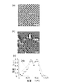
- FIG. 8A shows the first pupil function and the point image distribution.
- a region where light is not substantially shielded is shown in white.
- the non-shielding region is represented by a substantially circular shape.
- the horizontal axis indicates the number of pixel units in the CCD camera.
- the light intensity distribution substantially follows a Gaussian distribution.
- the half width corresponds to the resolution, and here, the half width of the graph is 8.8.
- FIG. 8B shows the second pupil function and the point image distribution.
- the non-shielding region is shown in white.
- the non-shielding region is represented by a substantially circular shape.
- the non-shielding region of the second pupil function is smaller than that of the first pupil function.
- Such a second pupil function can be said to be an apodization of the first pupil function.
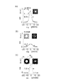
- FIG. 8C shows the difference between the first pupil function and the second pupil function and the difference between these point image distributions.
- a region 8a indicates a region that is a non-shielding region in both the first pupil function and the second pupil function
- a region 8b is a light of the first pupil function and the second pupil function.
- a region with different shielding is shown
- a region 8c shows a region that is a shielding region in both the first pupil function and the second pupil function.
- the full width at half maximum is 7.0. Thus, the resolution can be improved by the difference between the point image distributions of different pupil functions.
- the observation apparatus 100 can obtain a clear image from one frame image, and the temporal resolution of the observation apparatus 100 depends on the resolution of the image information generation unit 106.
- the observation apparatus 100 can acquire a 500 Hz image.
- the observation apparatus 100 has a time resolution several tens to several hundreds times that of a so-called scanning fluorescence microscope, and the observation apparatus 100 is preferably used for observing a biological material, for example.
- a 60 ⁇ objective lens is used as the objective lens in the fluorescence microscope 3, but the magnification of the objective lens is not particularly limited.
- a 150 ⁇ objective lens may be used.
- FIG. 9A shows a schematic diagram in a state where light is not shielded. Such a state is realized, for example, by setting the reflectance to be the maximum value in all the pixels of the reflective liquid crystal mirror array.
- FIG. 9B shows a point image distribution on the XZ plane when a shielding area (non-shielding area) is set as shown in FIG. 9A. Also here, an object to be observed having a size smaller than the diffraction limit of the microscope (for example, a fluorescent bead having a diameter of 100 nm) was used.
- Fig. 10 (a) shows the first pupil function.
- the first pupil function is a donut-shaped function defined by the inner ring and the outer ring.
- a region between the inner ring and the outer ring does not block light, whereas a region surrounded by the inner ring and a region outside the outer ring block light.
- the diameter of the circumference that defines the inner ring is 104 ⁇ m, and the diameter of the circumference that defines the outer ring is 312 ⁇ m.
- FIG. 10B shows a point image distribution in the case of the first pupil function.
- FIG. 11 (a) shows the second pupil function.
- the second pupil function is also a donut-shaped function defined by the inner ring and the outer ring. Even in the second pupil function, the region between the inner ring and the outer ring does not block light, whereas the region surrounded by the inner ring and the region outside the outer ring block light.
- the diameter of the circumference defining the inner ring is 312 ⁇ m, and the diameter of the circumference defining the outer ring is 624 ⁇ m.
- FIG. 11B shows a point image distribution in the case of the second pupil function.
- FIG. 12 (a) shows the point image distributions in the X-axis direction of FIGS.
- the peak intensity of light is relatively high.
- the horizontal resolution is 226 nm.
- the peak intensity is lowered by setting the donut-shaped pupil function.
- FIG. 12B shows the point image distributions in the Z-axis direction of FIGS. 9B, 10B, and 11B, respectively, with reference numerals 9b, 10b, and 11b.
- the peak intensity of light is relatively high.
- the optical axis resolution is 940 nm. Note that the peak intensity decreases as the shielding area increases.
- the position indicating the peak intensity deviates from zero due to the setting of the donut-shaped pupil function.
- FIG. 13A shows the difference between the point image distributions of the first and second pupil functions.
- the horizontal axis represents the X axis
- the vertical axis represents the Z axis.
- FIG. 13B shows the point image distribution in the X direction
- FIG. 13C shows the point image distribution in the Z direction.
- the resolution in the horizontal direction is 147 nm
- the resolution in the optical axis direction is 525 nm.
- FIG. 13B and FIG. 13C show the point image distribution when light is not shielded by reference numeral 9b.
- the resolution in the horizontal direction and the optical axis direction can be improved by the difference between the point image distributions of different pupil functions.
- the horizontal resolution and the vertical resolution can be further improved by changing the focal position of the incoming light.
- FIG. 14A shows the difference in the point image distribution obtained by appropriately moving the fourth and fifth relay lenses 102k and 102m in the observation apparatus 100 shown in FIG.
- FIG. 14B shows the point image distribution in the X direction
- FIG. 14C shows the point image distribution in the Z direction.
- the resolution in the horizontal direction is 108 nm
- the resolution in the optical axis direction is 463 nm.
- the point image distribution when light is not blocked is indicated by reference numeral 9b.
- the difference between the point image distributions of different pupil functions in the observation apparatus 100 is similar to digital image processing (digital high-pass filter), but according to the observation apparatus 100, the resolution (particularly the optical axis resolution) is higher than that of digital image processing. ) Can be further improved.
- Gaussian filter processing is performed as digital image processing.
- FIG. 15A shows the point image distribution on the XZ plane
- FIGS. 15B to 15D show the point image distributions after the digital image processing.
- FIG. 15B shows the result of performing Gaussian filter processing with a standard deviation of 2 pixels
- FIG. 15C shows the intensity of the point image distribution of Gaussian filter processing with a standard deviation of 2 pixels in half
- FIG. 15D shows the result of Gaussian filter processing with a standard deviation of 5 pixels.
- FIG. 16A is a diagram showing the difference between the point image distribution shown in FIG. 15A and the point image distribution shown in FIG. 15B, and FIG. 16B and FIG. These show the point image distributions of the X axis and Z axis in FIG.
- the resolution in the horizontal direction is 104 nm, and the resolution in the optical axis direction is 613 nm.
- a point image distribution not subjected to digital image processing is indicated by reference numeral 15a for comparison.
- FIG. 17A is a diagram showing the difference between the point image distribution shown in FIG. 15A and the point image distribution shown in FIG. 15D
- FIG. 17B and FIG. These show the point image distributions of the X axis and Z axis in FIG.
- the resolution in the horizontal direction is 157 nm
- the resolution in the optical axis direction is 809 nm.
- a point image distribution not subjected to digital image processing is indicated by reference numeral 15a for comparison. Even when digital image processing is performed with a relatively high standard deviation, the resolution of both the horizontal axis and the optical axis can be improved.
- FIG. 18A is a diagram showing a difference between the point image distribution shown in FIG. 15A and the point image distribution shown in FIG. 15C
- FIG. 18B and FIG. Respectively show the point image distributions of the X-axis and the Z-axis in FIG.
- the resolution in the horizontal direction is 181 nm
- the resolution in the optical axis direction is 730 nm.
- a point image distribution not subjected to digital image processing is indicated by reference numeral 15a for comparison. In this way, by reducing the intensity of light to be subtracted from the original point image distribution, it is possible to prevent the tail of the point image distribution obtained by subtraction from becoming negative.
- the resolution of the point image distribution can also be improved by digital image processing.
- the difference in the point image distribution by the observation apparatus 100 is the same as that of such digital image processing, but is not actually the same. This is because a two-dimensional process is performed in digital image processing, whereas a three-dimensional process is performed in the observation apparatus 100, and aberrations exist in an actual optical system, and are not necessarily limited. The reason is considered not to be linear.
- the resolution can be further improved.
- FIG. 19 is a schematic diagram of an observation apparatus 200 according to Embodiment 2 of the present invention.
- the observation apparatus 200 observes the observation object 1 based on the incoming light 2 coming from the observation object 1.
- the observation apparatus 200 includes an optical system 202, a conversion unit 204 that converts the incoming light 2 into first converted light using a first pupil function, and converts the incoming light into second converted light using a second pupil function, and image information.
- a generation unit 106, a function change unit 108, and a position change unit 110 are provided.
- the optical system 202 is provided after the imaging plane of the fluorescence microscope 3.
- the optical system 202 includes a slit 102a, a first relay lens 102b, a second relay lens 102c and a first mirror 102d, a first polarizing beam splitter 102e, a fifth relay lens 102m, a mirror 102j, and a beam splitter 202h. Is provided.
- the constituent elements other than the beam splitter 202h and the conversion unit 204 provided in the optical system 202 have the same functions as the corresponding constituent elements included in the observation apparatus 100 described in the first embodiment. Is omitted.
- the polarizing beam splitter 202h returns the optical path divided by the polarizing beam splitter 102e to one optical path.
- the optical system 202 is not limited to the configuration illustrated in FIG. 19 as long as the incoming light 2 can be guided to the conversion unit 204 and the converted light can be guided to the image information generation unit 106.
- the combination and arrangement of the relay lens, mirror, and polarization beam splitter are arbitrary.
- a relay optical system including two lenses 102b, 102c, or 102m is used as a relay system for transmitting a real image acquired by the fluorescence microscope 3 to the image information generation unit 106.
- a single lens is used.
- An optical system may be employed.
- the conversion unit 204 includes a third conversion unit 204a that converts the incoming light 2 with the first pupil function, and a fourth conversion unit 204b that converts the incoming light 2 with the second pupil function.
- the 3rd conversion part 204a and the 4th conversion part 204b are arrange
- transmissive members are used as the third conversion unit 204a and the fourth conversion unit 204b.
- the transmissive member is a transmissive liquid crystal array.
- image information related to the object to be observed 1 is generated based on the first converted light obtained by converting the incoming light 2 by the first pupil function and the second converted light converted by the second pupil function. . Therefore, the spread of the intensity distribution of the incoming light 2 can be suppressed. As a result, it is possible to obtain a clear image in which blur is eliminated from the two-dimensional tomographic image information obtained by using the incoming light 2.
- a member that converts the incoming light 2 into the first converted light with the first pupil function and converts the incoming light 2 into the second converted light with the second pupil function may be a transmission type member instead of a reflective type member. Good.
- the reflection type member and the transmission type member can be easily obtained at low cost as ready-made products. Therefore, the incoming light can be converted into the first converted light and the second converted light, respectively, with an inexpensive configuration without requiring a special configuration as the conversion unit.
- the conversion unit may be a DMD (Digital Micromirror Device).
- the DMD is an element in which micro-size mirrors are spread. By controlling the mirror in two states of on / off, the reflection direction of light can be adjusted, and a difference in brightness can be produced. By switching the state of each mirror at high speed, gradation can be realized by time division.
- the number of conversion units is not limited to two.
- the first conversion unit converts the incoming light 2 into the first converted light using the first pupil function
- the second The conversion unit converts the incoming light 2 into the second converted light using the second pupil function
- the third conversion unit converts the incoming light 2 into the third converted light using the third pupil function.
- the image information generation unit generates image information related to the object to be observed based on the first converted light, the second converted light, and the third converted light.
- the conversion unit converts the incoming light 2 into the first converted light with the first pupil function, and then changes the pupil function given to the conversion unit by the function changing unit into the second pupil function. After the function changing unit changes to the second pupil function, the converting unit converts the incoming light 2 into the second converted light using the second pupil function.
- the image information generation unit generates image information related to the object to be observed based on the first converted light and the second converted light.
- the following experiment was performed.
- an observation object in which a HeLa cell line was fixed on a slide glass with formalin was observed.
- a fluorescent dye (phalloidin obtained by crosslinking Alexa 488) was added to the object to be observed. Phalloidin binds to actin fibers, and intracellular actin fibers are stained with a fluorescent dye crosslinked to phalloidin.
- the object to be observed was irradiated with light having a wavelength of 488 nm, and fluorescence of 510 nm or more coming from the object to be observed was observed.
- the objective lens an objective lens having a magnification of 150 times with a numerical aperture of 1.45 was selected.
- the magnification of the relay optics composed of the first relay lens 102b and the second relay lens 102c is twice.
- the first converter 104a is provided with a donut-shaped first pupil function having an outer ring diameter of 728 ⁇ m and an inner ring diameter of 104 ⁇ m
- the second converter 104b is provided with a donut-shaped first pupil function having an outer ring diameter of 520 ⁇ m and an inner ring diameter of 104 ⁇ m.
- a two-pupil function was given to obtain a difference image between the images F 1 and F 2 .
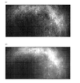
- FIG. 20 is a diagram showing an image observed by this example and an image observed by a conventional fluorescence microscope. It is the image which observed the actin fiber in the cell with the observation apparatus 100.
- FIG. FIG. 20A shows a difference image between the image F 1 and the image F 2 observed according to the present embodiment.
- FIG. 20B shows an image observed with a conventional fluorescence microscope. In both cases, actin fibers fluorescently labeled by Alexa 488 are confirmed. 20A and 20B are compared, it can be confirmed that the background light of the image of FIG. 20A is reduced and the actin fibers can be observed more clearly.
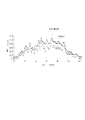
- FIG. 21 is a graph showing the fluorescence intensity distribution in the cross-sectional portion indicated by the dotted line in FIG. Figure 21 (a) shows the intensity distribution of the obtained cross-sectional portion from the difference image to which the present embodiment the image F 1 are observed by the examples and the image F 2 (see FIG. 20 (a)).
- FIG. 21B shows an intensity distribution of a cross-sectional portion obtained from an image (see FIG. 20B) observed with a conventional fluorescence microscope. By this example, it can be confirmed that the contrast of the fluorescence microscope image is improved.
- a donut-shaped first pupil function having an outer ring diameter of 416 ⁇ m and an inner ring diameter of 104 ⁇ m is given to the first converter 104a
- a donut having an outer ring diameter of 624 ⁇ m and an inner ring diameter of 312 ⁇ m is given to the second converter 104b. It gives a second pupil function of the shape, and obtains the difference image of the image F 1 and image F 2.
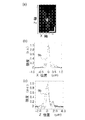
- FIG. 22 is a diagram showing an image observed by this example and an image observed by a conventional fluorescence microscope. It is the image which observed the actin fiber in the cell with the observation apparatus 100.
- FIG. FIG. 22A shows an image observed with a conventional fluorescence microscope
- FIG. 22B shows a difference image between the images F 1 and F 2 observed in this example. In both cases, actin fibers fluorescently labeled by Alexa 488 are confirmed. Comparing FIG. 22 (a) and FIG. 22 (b), it can be confirmed that the background light of the image of FIG. 22 (b) is reduced and the actin fibers can be observed more clearly.
- FIG. 23 shows the fluorescence intensity distribution in the cross-sectional portion shown by the dotted lines in FIG. 22 (a) and FIG. 22 (b). By this example, it can be confirmed that the contrast of the fluorescence microscope image is improved.
- FIG. 24 (a) shows an image observed with a conventional fluorescence microscope.
- FIG. 24B shows an enlarged view of the region surrounded by the broken line in FIG. 24A
- FIG. 24C shows the fluorescence intensity distribution in the broken line part in FIG.
- FIG. 25A shows an image obtained by performing digital image processing on an image observed with a conventional fluorescence microscope. This image was obtained by the difference between the original image and an image obtained by a Gaussian filter having a standard deviation of 2 pixels.
- FIG. 25B shows an enlarged view of the region surrounded by the broken line in FIG. 25A
- FIG. 25C shows the fluorescence intensity distribution in the broken line part in FIG.
- FIG. 25C shows the fluorescence intensity distribution shown in FIG. 24C together with reference numeral 24c.
- a Gaussian filter improves the contrast ratio.
- FIG. 26 (a) shows an image obtained by performing digital image processing on an image observed with a conventional fluorescence microscope. This image was obtained by the difference between the original image and an image obtained by a Gaussian filter having a standard deviation of 5 pixels.
- FIG. 26B shows an enlarged view of a region surrounded by a broken line in FIG. 26A
- FIG. 26C shows a fluorescence intensity distribution in a broken line part in FIG.
- the fluorescence intensity distribution shown in FIG. 24 (c) is also indicated by reference numeral 24c.
- a Gaussian filter improves the contrast ratio.
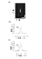
- FIG. 27A shows an image observed with the observation apparatus 100.
- FIG. 27B shows an enlarged view of a region surrounded by a broken line in FIG. 27A
- FIG. 27C shows a fluorescence intensity distribution in a broken line part in FIG. 27B.
- FIG. 27C also shows the fluorescence intensity distribution shown in FIG.
- the contrast ratio is improved by the observation apparatus 100. As can be understood from the comparison between FIG. 27C, FIG. 25C, and FIG. 26C, the observation apparatus 100 was able to further improve the contrast ratio as compared with the digital image processing. .
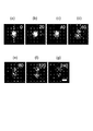
- FIG. 28A shows an image of cadherin observed with the observation apparatus 100 at a certain time.
- 28 (b), FIG. 28 (c), FIG. 28 (d), FIG. 28 (e), FIG. 28 (f), and FIG. 28 (g) are respectively 20 ms and 40 ms with reference to FIG. 28 (a).
- Images after 60 ms, 80 ms, 120 ms, and 240 ms are shown.
- FIGS. 28 (a) to 28 (f) cadherin detachment was observed.
- FIG. 29 shows the time change of the light intensity distribution in the portion indicated by the broken line in FIG.
- 0 ms, 40 ms, 50 ms, 54 ms, 56 ms, 58 ms, 60 ms, 120 ms, and 240 ms respectively indicate fluorescence intensity distributions with 0 ms as a reference time.
- the cadherin divergence could also be grasped from the temporal change in the fluorescence intensity distribution.
- the observation apparatus and observation method according to the present invention can be widely used in the field of image generation using an optical microscope. Further, by incorporating the observation apparatus and observation method according to the present invention into an optical microscope, the added value of the optical microscope itself is increased, and it can be widely used in the field of optical microscopes.
Landscapes
- Physics & Mathematics (AREA)
- Engineering & Computer Science (AREA)
- Computer Vision & Pattern Recognition (AREA)
- Multimedia (AREA)
- Chemical & Material Sciences (AREA)
- Analytical Chemistry (AREA)
- General Physics & Mathematics (AREA)
- Optics & Photonics (AREA)
- General Engineering & Computer Science (AREA)
- Microscoopes, Condenser (AREA)
- Investigating, Analyzing Materials By Fluorescence Or Luminescence (AREA)
- Image Input (AREA)
Abstract
Description
図1は、本発明の実施形態1に係る観察装置100の模式図である。観察装置100は、被観察物1から到来する到来光2に基づいて被観察物1を観察する。観察装置100は、光学系102と、到来光2を第1瞳関数で第1変換光に変換し、かつ到来光を第2瞳関数で第2変換光に変換する変換部104と、画像情報生成部106と、瞳関数変更部108と、焦点位置変更部110とを備える。なお、本明細書において、瞳関数変更部108および焦点位置変更部110をそれぞれ、関数変更部108および位置変更部110と呼ぶことがある。
図19は、本発明の実施形態2に係る観察装置200の模式図である。観察装置200は、被観察物1から到来する到来光2に基づいて被観察物1を観察する。観察装置200は、光学系202と、到来光2を第1瞳関数で第1変換光に変換し、かつ到来光を第2瞳関数で第2変換光に変換する変換部204と、画像情報生成部106と、関数変更部108と、位置変更部110とを備える。光学系202は、蛍光顕微鏡3の結像面以降に設けられている。光学系202は、スリット102aと、第1リレーレンズ102b、第2リレーレンズ102c及び第1ミラー102dと、第1偏光ビームスプリッタ102eと、第5リレーレンズ102mと、ミラー102jと、ビームスプリッタ202hとを備える。
2 到来光
100 観察装置
104 変換部
104a 第1変換部
104b 第2変換部
106 画像情報生成部
108 瞳関数変更部
110 焦点位置変更部
200 観察装置
204 変換部
204a 第3変換部
204b 第4変換部
Claims (15)
- 被観察物から到来する到来光に基づいて前記被観察物を観察する観察装置であって、
前記到来光を第1瞳関数で第1変換光に変換し、かつ前記到来光を第2瞳関数で第2変換光に変換する変換部と、
前記第1変換光と、前記第2変換光とに基づいて、前記被観察物に関する画像情報を生成する画像情報生成部と
を備えた観察装置。 - 前記第1瞳関数と前記第2瞳関数とのうちの少なくとも一方を変更する瞳関数変更部を更に備えた、請求項1に記載の観察装置。
- 前記変換部は、反射型部材又は透過型部材を含む、請求項1または2に記載の観察装置。
- 前記第2瞳関数は、前記第1瞳関数とは異なる、請求項1から3の何れか一項に記載の観察装置。
- 前記到来光の焦点位置を変更する焦点位置変更部を更に備えた、請求項1から4の何れか一項に記載の観察装置。
- 前記変換部は、
前記到来光を前記第1瞳関数で変換する第1変換部と、
前記到来光を前記第2瞳関数で変換する第2変換部と
を含む、
請求項1から5の何れか一項に記載の観察装置。 - 前記第1瞳関数及び前記第2瞳関数は、互いに内輪と外輪とを有する二次元ドーナツ形状の関数であり、
前記第1変換部及び前記第2変換部は、夫々の内輪と外輪とで囲まれる領域を、前記第1瞳関数及び前記第2瞳関数の非遮蔽領域として機能させる、請求項6に記載の観察装置。 - 前記二次元ドーナツ形状の関数において、前記内輪の径と前記外輪の径との比の値は、1/6~4/5である、請求項7に記載の観察装置。
- 前記変換部は、前記到来光の強度を変調することによって前記到来光を前記第1変換光および前記第2変換光に変換する、請求項1から8の何れか一項に記載の観察装置。
- 被観察物から到来する到来光に基づいて前記被観察物を観察する観察方法であって、
前記到来光を第1瞳関数で第1変換光に変換し、かつ前記到来光を第2瞳関数で第2変換光に変換する変換ステップと、
前記第1変換光と、前記第2変換光とに基づいて、前記被観察物に関する画像情報を生成する画像情報生成ステップと
を包含する観察方法。 - 前記第1瞳関数と前記第2瞳関数とのうちの少なくとも一方を変更する瞳関数変更ステップを更に包含する、請求項10に記載の観察方法。
- 前記変換ステップは、
前記到来光を前記第1瞳関数で変換する第1変換ステップと、
前記到来光を前記第2瞳関数で変換する第2変換ステップと
を含む、請求項10又は請求項11に記載の観察方法。 - 前記変換ステップにおいて、前記第2瞳関数は、前記第1瞳関数とは異なる、請求項10から12の何れか一項に記載の観察装置。
- 前記到来光の焦点位置を変更する焦点位置変更ステップを更に包含する、請求項10から請求項13の何れか一項に記載の観察方法。
- 前記変換ステップにおいて、前記到来光の強度を変調することによって前記到来光を前記第1変換光および前記第2変換光に変換する、請求項10から14の何れか一項に記載の観察装置。
Priority Applications (2)
| Application Number | Priority Date | Filing Date | Title |
|---|---|---|---|
| US13/639,200 US9081176B2 (en) | 2010-04-05 | 2011-02-07 | Observation system and observation method |
| JP2012509339A JP5733670B2 (ja) | 2010-04-05 | 2011-02-07 | 観察装置及び観察方法 |
Applications Claiming Priority (2)
| Application Number | Priority Date | Filing Date | Title |
|---|---|---|---|
| JP2010086945 | 2010-04-05 | ||
| JP2010-086945 | 2010-04-05 |
Publications (1)
| Publication Number | Publication Date |
|---|---|
| WO2011125370A1 true WO2011125370A1 (ja) | 2011-10-13 |
Family
ID=44762336
Family Applications (1)
| Application Number | Title | Priority Date | Filing Date |
|---|---|---|---|
| PCT/JP2011/052543 Ceased WO2011125370A1 (ja) | 2010-04-05 | 2011-02-07 | 観察装置及び観察方法 |
Country Status (3)
| Country | Link |
|---|---|
| US (1) | US9081176B2 (ja) |
| JP (1) | JP5733670B2 (ja) |
| WO (1) | WO2011125370A1 (ja) |
Cited By (2)
| Publication number | Priority date | Publication date | Assignee | Title |
|---|---|---|---|---|
| JP2021503635A (ja) * | 2017-11-16 | 2021-02-12 | エスディー オプティクス、インコーポレイテッド | 機能モジュール及び該機能モジュールを備えた顕微鏡 |
| US12545713B2 (en) | 2019-05-14 | 2026-02-10 | Progen Co., Ltd. | Modified immunoglobulin Fc-fusion protein and use thereof |
Families Citing this family (1)
| Publication number | Priority date | Publication date | Assignee | Title |
|---|---|---|---|---|
| JP6112872B2 (ja) * | 2013-01-18 | 2017-04-12 | キヤノン株式会社 | 撮像システム、画像処理方法、および撮像装置 |
Citations (2)
| Publication number | Priority date | Publication date | Assignee | Title |
|---|---|---|---|---|
| JPS56137324A (en) * | 1980-03-10 | 1981-10-27 | Bii Kurei Bikutaa | Microscope |
| JPH11101942A (ja) * | 1997-08-01 | 1999-04-13 | Carl Zeiss Jena Gmbh | 顕微鏡におけるアダプティブ光学装置 |
Family Cites Families (10)
| Publication number | Priority date | Publication date | Assignee | Title |
|---|---|---|---|---|
| US4561731A (en) | 1980-03-10 | 1985-12-31 | Kley Victor B | Electronic illumination control |
| US5686960A (en) * | 1992-01-14 | 1997-11-11 | Michael Sussman | Image input device having optical deflection elements for capturing multiple sub-images |
| US5587832A (en) | 1993-10-20 | 1996-12-24 | Biophysica Technologies, Inc. | Spatially light modulated confocal microscope and method |
| JPH09197289A (ja) * | 1996-01-23 | 1997-07-31 | Nikon Corp | 顕微鏡 |
| US6771417B1 (en) | 1997-08-01 | 2004-08-03 | Carl Zeiss Jena Gmbh | Applications of adaptive optics in microscopy |
| JP3634343B2 (ja) | 2001-09-03 | 2005-03-30 | 株式会社林創研 | デジタル制御走査方法および装置 |
| JP2005091865A (ja) * | 2003-09-18 | 2005-04-07 | Olympus Corp | 被写界深度拡大システム |
| JP4615886B2 (ja) * | 2004-04-01 | 2011-01-19 | オリンパス株式会社 | 走査型光学顕微鏡 |
| JP2007316133A (ja) * | 2006-05-23 | 2007-12-06 | Nikon Corp | 観察装置 |
| JP5040191B2 (ja) * | 2006-06-29 | 2012-10-03 | 富士通株式会社 | マイクロインジェクション装置及び自動焦点調整方法 |
-
2011
- 2011-02-07 US US13/639,200 patent/US9081176B2/en not_active Expired - Fee Related
- 2011-02-07 JP JP2012509339A patent/JP5733670B2/ja not_active Expired - Fee Related
- 2011-02-07 WO PCT/JP2011/052543 patent/WO2011125370A1/ja not_active Ceased
Patent Citations (2)
| Publication number | Priority date | Publication date | Assignee | Title |
|---|---|---|---|---|
| JPS56137324A (en) * | 1980-03-10 | 1981-10-27 | Bii Kurei Bikutaa | Microscope |
| JPH11101942A (ja) * | 1997-08-01 | 1999-04-13 | Carl Zeiss Jena Gmbh | 顕微鏡におけるアダプティブ光学装置 |
Cited By (5)
| Publication number | Priority date | Publication date | Assignee | Title |
|---|---|---|---|---|
| JP2021503635A (ja) * | 2017-11-16 | 2021-02-12 | エスディー オプティクス、インコーポレイテッド | 機能モジュール及び該機能モジュールを備えた顕微鏡 |
| KR20230070076A (ko) * | 2017-11-16 | 2023-05-19 | 주식회사 에스디옵틱스 | 기능 모듈 및 기능 모듈이 장착된 현미경 |
| JP7338100B2 (ja) | 2017-11-16 | 2023-09-05 | エスディー オプティクス、インコーポレイテッド | 機能モジュール及び該機能モジュールを備えた顕微鏡 |
| KR102773093B1 (ko) * | 2017-11-16 | 2025-03-06 | 주식회사 에스디옵틱스 | 기능 모듈 및 기능 모듈이 장착된 현미경 |
| US12545713B2 (en) | 2019-05-14 | 2026-02-10 | Progen Co., Ltd. | Modified immunoglobulin Fc-fusion protein and use thereof |
Also Published As
| Publication number | Publication date |
|---|---|
| US20130026347A1 (en) | 2013-01-31 |
| US9081176B2 (en) | 2015-07-14 |
| JPWO2011125370A1 (ja) | 2013-07-08 |
| JP5733670B2 (ja) | 2015-06-10 |
Similar Documents
| Publication | Publication Date | Title |
|---|---|---|
| JP6282641B2 (ja) | 顕微鏡およびspim顕微鏡検査方法 | |
| JP6444869B2 (ja) | 誘導放出抑制顕微鏡検査 | |
| US8019136B2 (en) | Optical sectioning microscopy | |
| US20190302437A1 (en) | Microscopy Devices, Methods and Systems | |
| US20200150446A1 (en) | Method and System for Improving Lateral Resolution in Optical Scanning Microscopy | |
| JP6360825B2 (ja) | 結像光学系、照明装置および観察装置 | |
| US20180164564A1 (en) | Assembly and method for beam shaping and for light sheet microscopy | |
| JP2018055082A (ja) | 変換装置、照明装置および光シート蛍光顕微鏡 | |
| US20120019647A1 (en) | Method and configuration for the optical detection of an illuminated specimen | |
| EP3683611B1 (en) | Microscope and observation method | |
| US20110267688A1 (en) | Microscopy Method and Microscope With Enhanced Resolution | |
| CN110520779B (zh) | 像差校正方法和光学装置 | |
| WO2016199179A1 (ja) | 構造化照明顕微鏡システム、方法及びプログラム | |
| WO2017158695A1 (ja) | 点像分布関数の測定装置、測定方法、画像取得装置および画像取得方法 | |
| WO2015098242A1 (ja) | 標本観察装置および標本観察方法 | |
| JP5733670B2 (ja) | 観察装置及び観察方法 | |
| JP6537153B2 (ja) | 光学情報検知装置及び顕微鏡システム | |
| JPH02247605A (ja) | レーザ走査蛍光顕微鏡 | |
| JP6467160B2 (ja) | 結像光学系、照明装置および観察装置 | |
| JP5765569B2 (ja) | 顕微鏡装置 | |
| Zakharov et al. | Holographic scanning microscopy–novel approach to digital holography and laser scanning microscopy | |
| JP7196422B2 (ja) | 顕微鏡システム | |
| EP4685542A1 (en) | Sample image acquisition device and sample image generation device | |
| WO2020058187A1 (en) | Confocal laser scanning microscope configured for generating line foci | |
| EP4492118A1 (en) | Hybrid differential defocus phase contrast |
Legal Events
| Date | Code | Title | Description |
|---|---|---|---|
| 121 | Ep: the epo has been informed by wipo that ep was designated in this application |
Ref document number: 11765272 Country of ref document: EP Kind code of ref document: A1 |
|
| WWE | Wipo information: entry into national phase |
Ref document number: 2012509339 Country of ref document: JP |
|
| WWE | Wipo information: entry into national phase |
Ref document number: 13639200 Country of ref document: US |
|
| NENP | Non-entry into the national phase |
Ref country code: DE |
|
| 122 | Ep: pct application non-entry in european phase |
Ref document number: 11765272 Country of ref document: EP Kind code of ref document: A1 |