WO2011125221A1 - 圧延材冷却制御装置、圧延材冷却制御方法、圧延材冷却制御プログラム - Google Patents
圧延材冷却制御装置、圧延材冷却制御方法、圧延材冷却制御プログラム Download PDFInfo
- Publication number
- WO2011125221A1 WO2011125221A1 PCT/JP2010/056453 JP2010056453W WO2011125221A1 WO 2011125221 A1 WO2011125221 A1 WO 2011125221A1 JP 2010056453 W JP2010056453 W JP 2010056453W WO 2011125221 A1 WO2011125221 A1 WO 2011125221A1
- Authority
- WO
- WIPO (PCT)
- Prior art keywords
- cooling
- detailed
- pattern
- rolled material
- cooling pattern
- Prior art date
- Legal status (The legal status is an assumption and is not a legal conclusion. Google has not performed a legal analysis and makes no representation as to the accuracy of the status listed.)
- Ceased
Links
Images







Classifications
-
- B—PERFORMING OPERATIONS; TRANSPORTING
- B21—MECHANICAL METAL-WORKING WITHOUT ESSENTIALLY REMOVING MATERIAL; PUNCHING METAL
- B21B—ROLLING OF METAL
- B21B45/00—Devices for surface or other treatment of work, specially combined with or arranged in, or specially adapted for use in connection with, metal-rolling mills
- B21B45/02—Devices for surface or other treatment of work, specially combined with or arranged in, or specially adapted for use in connection with, metal-rolling mills for lubricating, cooling, or cleaning
-
- B—PERFORMING OPERATIONS; TRANSPORTING
- B21—MECHANICAL METAL-WORKING WITHOUT ESSENTIALLY REMOVING MATERIAL; PUNCHING METAL
- B21B—ROLLING OF METAL
- B21B37/00—Control devices or methods specially adapted for metal-rolling mills or the work produced thereby
- B21B37/74—Temperature control, e.g. by cooling or heating the rolls or the product
- B21B37/76—Cooling control on the run-out table
Definitions
- a fourth feature of the rolling material cooling control device is the rolling material cooling control device according to any one of the first to third features.
- the cooling pattern calculation unit sets a parameter value in the simple cooling pattern calculated by the simple cooling pattern calculation unit as a target value for calculating the detailed cooling pattern, or an initial value for calculating the detailed cooling pattern.
- the detailed cooling pattern is calculated at the minimum speed and the maximum speed allowed for the desired detailed cooling pattern necessary for obtaining the desired material of the rolled material, and the parameter value in the simplified cooling pattern is set as the target value.
- the calculated detailed cooling pattern is output while the parameter value in the simplified cooling pattern is set to the initial value.
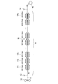
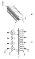
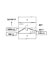
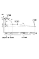
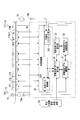
- FIG. 1 It is a figure showing an example of a conveyance table and a cooling bank in a hot sheet rolling line to which an embodiment of a rolling material cooling control device concerning the present invention is applied. It is a figure which shows an example of a structure of the cooling bank in the hot sheet rolling line to which embodiment of the rolling-material cooling control apparatus concerning this invention is applied. It is a block diagram which shows the structural example of the rolling material cooling control apparatus of 1st Embodiment which concerns on this invention. It is explanatory drawing for demonstrating the node in a rolling material. It is explanatory drawing which shows an example of a front
- the detailed cooling pattern calculation unit 34 generally uses the average temperature in the thickness direction of the rolled material indicated by the broken line 920 as a management value for cooling control.
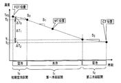
- the simplified cooling pattern calculation unit 33 includes the respective sections, that is, the initial air cooling section t 0 , the first cooling section t 1 , the second cooling section t 2 , the third cooling section t 3 , and the final cooling (air cooling) section t 4. Since the cooling rates S 0 , S 1 , S 2 , S 3 , and S 4 are necessary, the cooling rate calculated by the influence coefficient calculation unit 32 as the influence coefficient is input and used.
- the detailed cooling pattern calculation unit 34 does not directly calculate the detailed cooling pattern as shown in FIG. 9 from the detailed temperature model stored in the detailed temperature model storage unit 31, but the detailed temperature model.
- the influence coefficient calculation unit 32 calculates an influence coefficient
- the simple cooling pattern calculation unit 33 calculates a simple cooling pattern, and the calculated simple
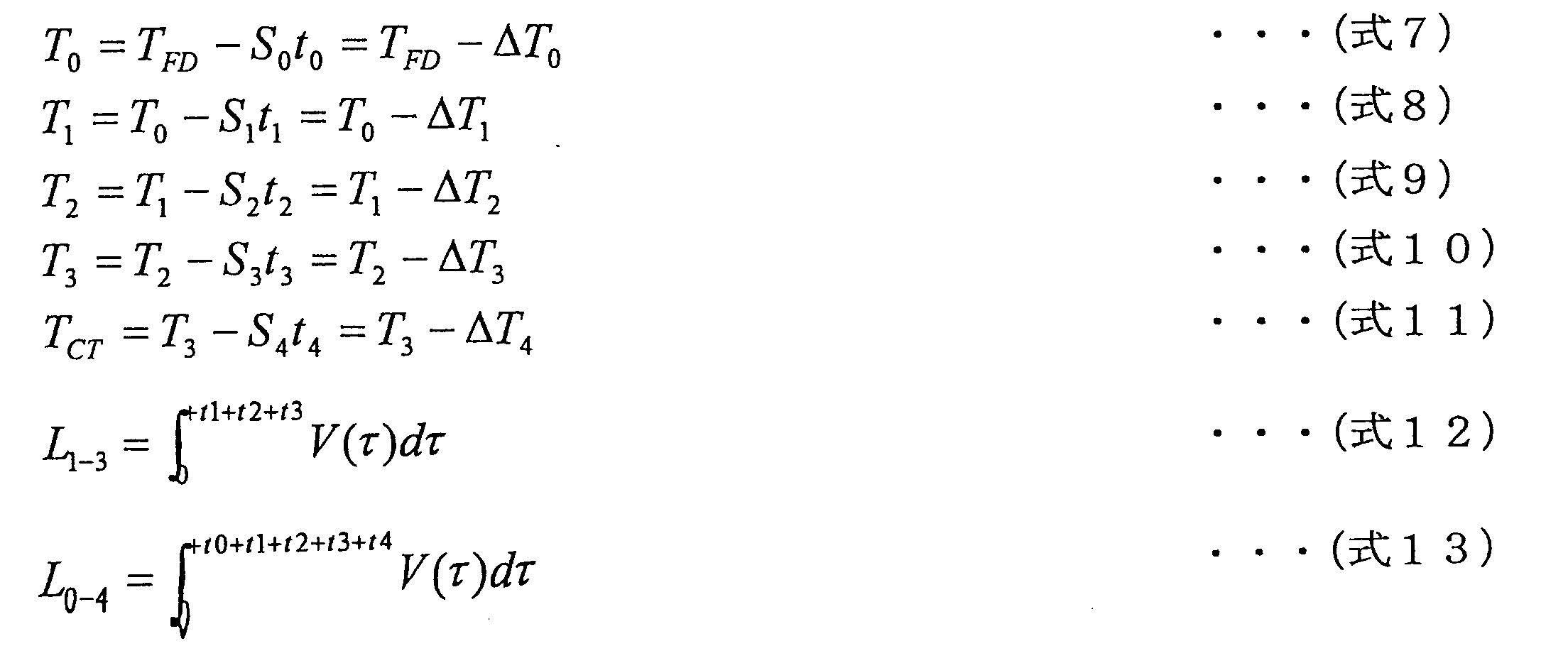
- T FD is finishing delivery temperature meter (FDT) 13 temperature
- T 0 end temperature of the initial air-cooled section t 0 is
- S 0 is the cooling rate in an initial cooling period t
- T 1 is the first end temperature of the cooling zone t 1
- S 1 is the cooling rate of the first cooling section t 1
- T 2 is the second cooling section t 2 of the termination temperature
- S 2 is the cooling rate of the second cooling section t 2
- T 3 is third cooling section t 3 of the end temperature
- S 3 third cooling rate cooling section t 4 the end temperature (coiling temperature)
- T M intermediate thermometer (MT) is The temperature at a certain position.
- the five simple parameters T 1 , T C , t 2 , S 1 and S 3 in the three-stage cooling are given to the simplified cooling pattern calculation unit 33 as values to be achieved.
- the value changes, as measurable or predictable parameters, given a temperature T FD of the finishing delivery temperature meter (FDT) 13, and the conveying speed V of the strip is.
- a distance L 0-4 from the finishing delivery thermometer (FDT) 13 to the winding thermometer (CT) 14 is a fixed value.
- the simple cooling pattern calculation unit 33 obtains a desired material of the rolled material 11 based on the influence coefficient calculated by the influence coefficient calculation unit 32 as described later with reference to FIGS. 11 and 12. Calculate the simple cooling pattern at the minimum speed and the maximum speed allowed for the desired detailed cooling pattern required for this, and whether the value of each parameter in the calculated simple cooling pattern is within the upper and lower limits of each parameter If the value of each parameter in the calculated simplified cooling pattern is not within the upper and lower limits of each parameter, the parameter is corrected from the lower priority parameter according to the priority of each parameter in the calculated simplified cooling pattern. Simplified cooling pattern so that each parameter value is within the upper and lower limits of each parameter. Calculated to.
- the parameters include, for example, the passing position of the rolled material, the temperature at the position, the cooling rate, and the air cooling time.
- the simple cooling pattern calculation unit 33 checks whether or not the calculated simple cooling pattern satisfies these constraint conditions, and adjusts the parameters so as to fall within the constraint conditions. There is a need to.
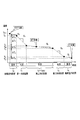
- the simple cooling pattern calculation unit 33 has the final position of the third cooling section t 3 in the calculated simple cooling pattern downstream from the most downstream side of the actual physical cooling bank, and has five important parameters T 1 , of T C, t 2, S 1 , S 3, when the cooling rate S 3 of the third cooling section t 3 the priority is the lowest, as shown in the broken line 1020 of FIG. 10, a third cooling Correct the cooling rate S 3 in the section t 3 to be the cooling rate S 3 UL is steeper slope than the target value, by shortening the third cooling section t 3 time, computational third cooling section the final position of t 3, to correct for the most downstream previous physical actual cooling bank (bank) 17n.
- the simplified cooling pattern calculation unit 33 of the present embodiment for example, as the conveyance speed of the rolled material, two types of the minimum speed and the maximum speed assumed for the rolled material are calculated, It is confirmed in advance whether or not a desired detailed cooling pattern such as a cooling rate and an air cooling time can be secured at both the minimum speed and the maximum speed of the rolled material.
- a conveyance speed assumed with the said rolling material you may of course calculate not only two kinds, the minimum speed and the maximum speed, but more than that.
- the detailed cooling pattern calculation unit 34 refers to the detailed temperature model stored in the detailed temperature model storage unit 31 while trying to turn on / off the valve 17n3 in the actual cooling bank (Bank) 17n, and performs simple cooling. Using the simple cooling pattern calculated by the pattern calculation unit 33 as a target value or initial value, a detailed cooling pattern is calculated in order to realize a desired material such as a desired strength and ductility of the rolled material.
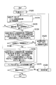
- FIG. 11 shows the first in the detailed cooling pattern calculation unit 34, that is, No. It is a flowchart which shows an example of the detailed cooling pattern calculation process until the completion of initial setting value calculation about 1 cut board.
- necessary information such as product information related to a rolling material to be cooled, a cooling rate, a target temperature, a constraint condition, and the like are input from the finishing mill setting calculation device 20 or the like (S1100).
- the detailed cooling pattern calculation unit 34 determines whether to use the simple cooling pattern calculated by the simple cooling pattern calculation unit 33 as an initial value or a target value (S1150).
- the detailed cooling pattern calculation part 34 judges whether the said cutting board is the last cutting board (S1280), and when the said cutting board is the last cutting board (S1280 “Yes"), On the other hand, if it is determined that the cut plate is not the last cut plate (S1280 “No”), the number of the next cut plate is updated (S1290), and the process returns to Step 1310.
- the cooling control unit 35 determines the No. based on the parameter initial value setting calculated by the detailed cooling pattern calculation unit 34 as shown in FIG. Cooling control is performed for every two or more cut plates (cooling control units).
- an influence coefficient is calculated from the detailed temperature model, and a desired detailed cooling pattern necessary for obtaining a desired material of the rolled material 11 based on the influence coefficient.
- the detailed cooling pattern of the rolled material in the predetermined cooling section is calculated, so the calculation load when calculating the detailed cooling pattern is reduced. Not only is it small, but it is possible to avoid limits such as keeping parameters within the upper and lower limits when calculating a simple cooling pattern with a light calculation load.
- the rolling material cooling control device 30 of the first embodiment it is possible to easily avoid the constraint condition that impedes the realization of the detailed cooling pattern, and to easily realize the desired detailed cooling pattern and optimize it. Cooling control of the rolling material 11 can be executed.
- the reason for reducing the ON / OFF operation (operation) of the valve 17n3 in the cooling bank (Bank) 17n as much as possible is that the response of the valve 17n3 in the cooling bank (Bank) 17n is always delayed.
- the valve 1713 in the most upstream cooling bank (Bank) 171 is set as a pivot valve that is always ON (open)
- the finish side temperature changes even with the same rolled material 11. If the cooling control is executed in such a state, the valve 17n3 is turned ON / OFF toward the downstream side, and the cooling bank at the most downstream of the first cooling section (Bank)
- the ON / OFF state of the valve 17p3 at 17p changes.
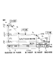
- the air cooling time in the second cooling section includes the conveyance speed of the rolled material, the ON valve position in the most downstream cooling bank (Bank) 17p in the first cooling section, and the most upstream cooling bank (Bank) 17r in the third cooling section. It depends on the relationship of the ON valve position at. In addition, since it is a general pattern that the conveyance speed of a rolling material becomes a constant speed after acceleration and then decelerates, the ON valve position in the most upstream cooling bank (Bank) 17r in the third cooling section changes in small increments. There is nothing.
- the last cooling section connected to the winding thermometer (CT) 14 is an air cooling section (in FIG. 6, the second air cooling section, FIG. 8, in the final air cooling section), although the time is short, the cooling bank (Bank) 17N-1, 17N close to the winding thermometer (CT) 14 is used by feedback control by the feedback (FB) control unit 353.
- the cooling in the last water cooling section (the first cooling section in FIG. 6 and the third cooling section in FIG. 8) is performed. The speed will be changed, and the cooling speed may change unintentionally.
- the cooling bank control unit 452 of the third embodiment changes the time of the water cooling section between the finishing-side thermometer (FDT) 13 and the intermediate thermometer (MT) 15 to set the cooling rate. Do not change.
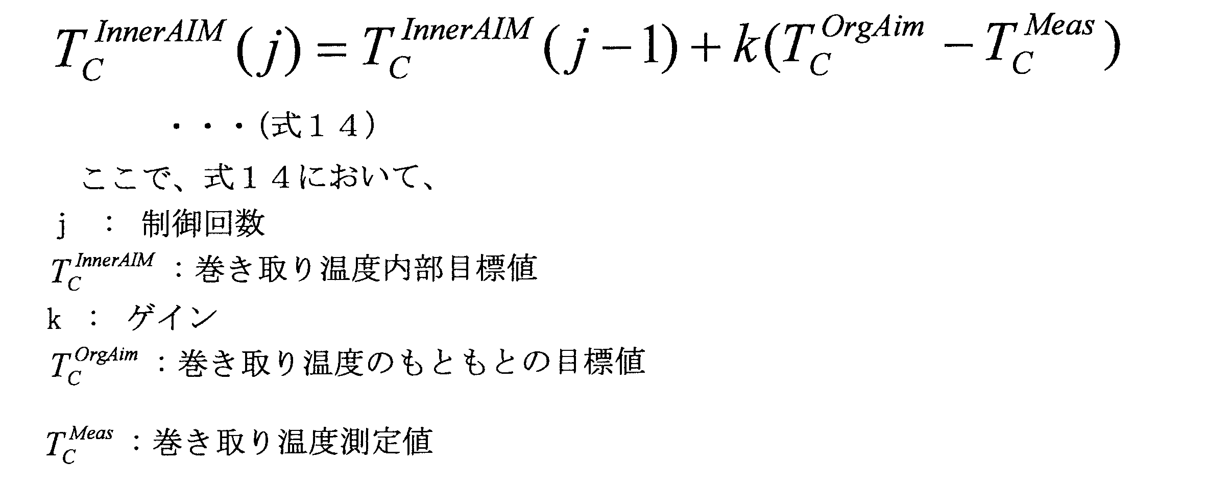
- the cooling bank control unit 452 of the third embodiment measures the winding temperature target value of the winding thermometer (CT) 14 and the winding temperature measurement in the winding thermometer (CT) 14.
- the intermediate temperature is adjusted so that the deviation from the value is corrected by adding to the internal winding temperature target value, and the winding temperature measurement value in the winding thermometer (CT) 14 achieves the corrected winding temperature target value.
- a cooling bank (Bank) between the meter (MT) 15 and the winding thermometer (CT) 14 is controlled.
- the influence coefficient is obtained from the detailed temperature model, and simple cooling is performed based on the influence coefficient. Since the pattern is obtained and the detailed cooling pattern is determined according to the simple cooling pattern, the calculation load when calculating the detailed cooling pattern is reduced, and the cooling control that can easily avoid the limit can be performed. It is possible to easily avoid the constraints that impede the realization of the detailed cooling pattern, and to achieve the desired material accurately by realizing the desired detailed cooling pattern and optimally executing the cooling control. Can do.
- the feedback (FB) control unit 353 is close to the winding thermometer (CT) 14 in order to keep an important cooling rate in securing a desired material.
- CT take-up thermometer
- the cooling bank control unit 452 of the third embodiment The deviation between the target value of the thermometer and the measured value at that thermometer is corrected by adding it to the internal temperature target value of that thermometer, and the internal temperature target value with the corrected temperature measurement value at that thermometer is corrected.
- a rolled material cooling control apparatus and a rolled material cooling control method according to the present invention are provided with a CPU, a storage unit storing a rolled material cooling control program for executing the same operation as in the above-described embodiment, and a computer device or a control device. Of course, it may be configured to be executed by software.
- the first to third embodiments are merely examples that are examples of the present invention.
- Various parameters, various numerical values, and the like are also examples, and can be modified without departing from the gist of the present invention. However, it is not limited to these.
- the detailed cooling pattern from the detailed temperature model is controlled. It has the effect of reducing the calculation load when obtaining, optimally performing cooling control, and efficiently controlling the materials necessary for manufacturing high-grade steel sheets, etc.
- Rolled material cooling control device, rolled material cooling control method, rolled material cooling control program in sheet rolling line, cold rolling line, etc. are targeted, and these rolled material cooling control device, rolled material cooling control method, rolled material cooling There is a high possibility of industrial use for control programs.
Landscapes
- Engineering & Computer Science (AREA)
- Mechanical Engineering (AREA)
- Control Of Metal Rolling (AREA)
Abstract
Description
まず、本発明にかかる圧延材冷却制御装置の実施形態が適用される熱間薄板圧延ラインについて説明する。
次に、本発明に係る第1実施形態の圧延材冷却制御装置の構成について説明する。
次に、以上のように構成された第1実施形態の圧延材冷却制御装置30の概略動作について説明する。
次に、以上のように構成された第1実施形態の圧延材冷却制御装置30の動作について説明する。
詳細温度モデル記憶部31は、熱間薄板圧延ラインで圧延された圧延材11を冷却する所定の冷却区間、例えば、仕上出側温度計(FDT)13から巻き取り温度計(CT)14までの搬送テーブル(ROT)10上における当該圧延材の温度変化を、数式により記述した詳細温度モデルを記憶している。


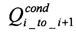
Qradは放射による熱流、Qwaterは水冷熱伝達による熱流、Qairは空冷対流熱伝達による熱流、


k:熱伝導率[J/(msK)]
A:面積[m2]
T:圧延材の温度[degC]
x:圧延材板厚方向の位置
下記に記号により示す多数のパラメータを用いて表わすと、例えば、下記式4のようになる。

k:熱伝導率[J/(msK)]
Ai→i+1:ノードiからノードi+1との間の断面積[m2]
Ti:ノードiにおける温度[degC]
d:ノード間の距離[m]
なお、差分方程式の解き方は、一般的な方法を用いればよい。また、図4においては圧延材の板厚方向のノード数のiを、4個としているが、これは一例である。一般に、同じ板厚であればノード数iを多くすれば、精度のよい計算結果が得られる。しかし、ノード数iがあまり多すぎても、計算負荷が高くなるだけで、精度の向上は鈍化する。そのため、ノード数iの選択は事前に検討する必要がある。なお、圧延材11のノードについては、WO2008/012881等に開示されている。
影響係数算出部32は、詳細温度モデル記憶部31によって複数のパラメータを用いて数式により表わされた詳細温度モデルに基づいて、圧延材11の温度変化の制御に必要な影響係数を算出する。

次に、簡略冷却パターン算出部33は、影響係数算出部32によって算出された影響係数に基づいて、圧延材の所望の材質(強度や延性等)を得るために必要な詳細冷却パターンを簡略化した簡略冷却パターンを算出する。
そして、詳細冷却パターン算出部34では、実際の冷却バンク(Bank)17nにおけるバルブ17n3のON/OFFを試行しながら、詳細温度モデル記憶部31に記憶された詳細温度モデルを参照して、簡略冷却パターン算出部33によって算出された簡略冷却パターンを目標値または初期値として使用して、圧延材の所望の強度や延性等の所望の材質を実現するために詳細冷却パターンを計算していく。
次に、第2実施形態の圧延材冷却制御装置について説明する。なお、第2実施形態の圧延材冷却制御装置の構成は、図3に示す第1実施形態の圧延材冷却制御装置30の構成と外見は同じであるので、図3に示す第1実施形態の圧延材冷却制御装置30の構成を参照して、第2実施形態の圧延材冷却制御装置の動作を説明する。
次に、第3実施形態の圧延材冷却制御装置40について説明する。
30,40…圧延材冷却制御装置
31…詳細温度モデル記憶部
32…影響係数算出部
33…簡略冷却パターン算出部
34…詳細冷却パターン算出部
35,45…冷却制御部
351…圧延材トラッキング部
352,452…冷却バンク制御部
353…フィードバック(FB)制御部
Claims (8)
- 所定の冷却区間における圧延材の温度変化を、パラメータを用い数式により記述した詳細温度モデルを記憶した詳細温度モデル記憶部と、
前記詳細温度モデル記憶部に記憶された前記詳細温度モデルに基づいて、前記圧延材の温度変化の制御に必要な影響係数を算出する影響係数算出部と、
前記影響係数算出部によって算出された前記影響係数に基づいて、前記圧延材の所望の材質を得るために必要な所望の詳細冷却パターンを簡略化した簡略冷却パターンを算出する簡略冷却パターン算出部と、
前記簡略冷却パターン算出部によって算出された前記簡略冷却パターンと、前記詳細温度モデル記憶部に記憶された前記詳細温度モデルとに基づいて、前記所定の冷却区間における前記圧延材の詳細冷却パターンを算出する詳細冷却パターン算出部と、
前記詳細冷却パターン算出部によって算出された前記詳細冷却パターンに基づいて、前記圧延材の冷却を制御する冷却制御部と、
を有することを特徴とする圧延材冷却制御装置。 - 請求項1記載の圧延材冷却制御装置において、
前記簡略冷却パターン算出部は、
前記圧延材の冷却速度を、直線または多項式または指数関数または対数の代数の数式により近似することにより、前記所定の冷却区間における当該圧延材の温度変化を幾何学的に近似して、前記所望の詳細冷却パターンを簡略化した簡略冷却パターンを算出する、
ことを特徴とする圧延材冷却制御装置。 - 請求項1または請求項2記載の圧延材冷却制御装置において、
前記簡略冷却パターン算出部は、
前記影響係数算出部によって算出された前記影響係数に基づいて、前記圧延材の所望の材質を得るために必要な所望の詳細冷却パターンに許される最低速度および最高速度で前記簡略冷却パターンを算出して、算出した前記簡略冷却パターンにおける各パラメータの値が、各パラメータの上下限範囲内であるか否かを判断し、
算出した前記簡略冷却パターンにおける各パラメータの値が各パラメータの上下限範囲内にない場合は、算出した前記簡略冷却パターンにおける各パラメータの優先順位に従って、優先順位の低いパラメータから修正し、算出した前記簡略冷却パターンにおける各パラメータの値が、各パラメータの上下限範囲内になるように簡略冷却パターンを算出する、
ことを特徴とする圧延材冷却制御装置。 - 請求項1~請求項3のいずれか一の請求項に記載の圧延材冷却制御装置において、
前記詳細冷却パターン算出部は、
前記簡略冷却パターン算出部によって算出された前記簡略冷却パターンにおけるパラメータの値を、前記詳細冷却パターン算出のための目標値とするか、あるいは前記詳細冷却パターン算出のための初期値として、前記圧延材の所望の材質を得るために必要な所望の詳細冷却パターンに許される最低速度および最高速度で前記詳細冷却パターンを算出し、
前記簡略冷却パターンにおけるパラメータの値を前記目標値とする場合には、その算出した前記詳細冷却パターンを出力する一方、
前記簡略冷却パターンにおけるパラメータの値を前記初期値とする場合には、その算出した前記詳細冷却パターンにおける各パラメータの値が、各パラメータの上下限範囲内であるか否かを判断し、算出した前記詳細冷却パターンにおける各パラメータの値が各パラメータの上下限範囲内にない場合、算出した前記詳細冷却パターンにおける各パラメータの優先順位に従って、優先順位の低いパラメータから修正し、算出した前記詳細冷却パターンにおける各パラメータの値が、各パラメータの上下限範囲内になるように前記詳細冷却パターンを算出する、
ことを特徴とする圧延材冷却制御装置。 - 請求項1~請求項3のいずれか一の請求項に記載の圧延材冷却制御装置において、
前記冷却制御部は、
前記圧延材の詳細冷却パターンとして、水冷の第一冷却区間、空冷の第二冷却区間、水冷の第三冷却区間の3段階を経る3段冷却パターンを行う場合、前記第一冷却区間の下流端のバルブを常にオンすることにより、前記第二冷却区間としての空冷時間を確保し、前記第三冷却区間の上流端でオンするバルブの位置のみを修正する、
ことを特徴とする圧延材冷却制御装置。 - 請求項1~請求項3のいずれか一の請求項に記載の圧延材冷却制御装置において、
前記冷却制御部は、
前記圧延材の所望の材質を実現するために与えられる所望の温度より所望の冷却速度の方が優先順位が高い場合、目標温度と測定温度との偏差をフィードバックし前記目標温度に加算して内部温度目標値とし、その内部温度目標値を達成するように、前記圧延材の冷却を制御する、
ことを特徴とする圧延材冷却制御装置。 - 圧延材を冷却する所定の冷却区間における当該圧延材の温度変化を、数式により記述した詳細温度モデルに基づいて、前記圧延材の温度変化の制御に必要な影響係数を算出するステップと、
算出された前記影響係数に基づいて、前記圧延材の所望の材質を得るために必要な所望の詳細冷却パターンを簡略化した簡略冷却パターンを算出するステップと、
算出された前記簡略冷却パターンと、前記詳細温度モデルとに基づいて、前記所定の冷却区間における前記圧延材の詳細冷却パターンを算出するステップと、
算出された前記詳細冷却パターンに基づいて、前記圧延材の冷却を制御するステップと、
を有する圧延材の圧延材冷却制御方法。 - コンピュータに、
圧延材を冷却する所定の冷却区間における当該圧延材の温度変化を、数式により記述した詳細温度モデルに基づいて、前記圧延材の温度変化の制御に必要な影響係数を算出するステップと、
算出された前記影響係数に基づいて、前記圧延材の所望の材質を得るために必要な所望の詳細冷却パターンを簡略化した簡略冷却パターンを算出するステップと、
算出された前記簡略冷却パターンと、前記詳細温度モデルとに基づいて、前記所定の冷却区間における前記圧延材の詳細冷却パターンを算出するステップと、
算出された前記詳細冷却パターンに基づいて、前記圧延材の冷却を制御するステップと、
を実行させるための圧延材の圧延材冷却制御プログラム。
Priority Applications (5)
| Application Number | Priority Date | Filing Date | Title |
|---|---|---|---|
| CN201080065946.6A CN102821885B (zh) | 2010-04-09 | 2010-04-09 | 轧制材料冷却控制装置、轧制材料冷却控制方法、轧制材料冷却控制程序 |
| JP2012509261A JP5462358B2 (ja) | 2010-04-09 | 2010-04-09 | 圧延材冷却制御装置、圧延材冷却制御方法、圧延材冷却制御プログラム |
| US13/640,167 US9056342B2 (en) | 2010-04-09 | 2010-04-09 | Rolled material cooling control apparatus, rolled material cooling control method, and rolled material cooling control program |
| KR1020127027085A KR101352224B1 (ko) | 2010-04-09 | 2010-04-09 | 압연재 냉각 제어 장치, 압연재 냉각 제어 방법, 압연재 냉각 제어 프로그램이 기록된 기록매체 |
| PCT/JP2010/056453 WO2011125221A1 (ja) | 2010-04-09 | 2010-04-09 | 圧延材冷却制御装置、圧延材冷却制御方法、圧延材冷却制御プログラム |
Applications Claiming Priority (1)
| Application Number | Priority Date | Filing Date | Title |
|---|---|---|---|
| PCT/JP2010/056453 WO2011125221A1 (ja) | 2010-04-09 | 2010-04-09 | 圧延材冷却制御装置、圧延材冷却制御方法、圧延材冷却制御プログラム |
Publications (1)
| Publication Number | Publication Date |
|---|---|
| WO2011125221A1 true WO2011125221A1 (ja) | 2011-10-13 |
Family
ID=44762206
Family Applications (1)
| Application Number | Title | Priority Date | Filing Date |
|---|---|---|---|
| PCT/JP2010/056453 Ceased WO2011125221A1 (ja) | 2010-04-09 | 2010-04-09 | 圧延材冷却制御装置、圧延材冷却制御方法、圧延材冷却制御プログラム |
Country Status (5)
| Country | Link |
|---|---|
| US (1) | US9056342B2 (ja) |
| JP (1) | JP5462358B2 (ja) |
| KR (1) | KR101352224B1 (ja) |
| CN (1) | CN102821885B (ja) |
| WO (1) | WO2011125221A1 (ja) |
Cited By (4)
| Publication number | Priority date | Publication date | Assignee | Title |
|---|---|---|---|---|
| JP2017051969A (ja) * | 2015-09-08 | 2017-03-16 | 株式会社日立製作所 | 巻取温度制御装置および巻取温度制御方法 |
| KR20200003218A (ko) * | 2017-06-26 | 2020-01-08 | 아르셀러미탈 | 금속 스트립의 온도를 결정하기 위한 방법 및 전자 디바이스, 관련 제어 방법, 컴퓨터 프로그램, 제어 장치 및 열간 압연 설비 |
| WO2020110201A1 (ja) * | 2018-11-27 | 2020-06-04 | 日本電気株式会社 | 情報処理装置 |
| WO2021033723A1 (ja) * | 2019-08-21 | 2021-02-25 | Jfeスチール株式会社 | 厚鋼板の製造設備及び製造方法 |
Families Citing this family (16)
| Publication number | Priority date | Publication date | Assignee | Title |
|---|---|---|---|---|
| WO2004084868A1 (en) | 2003-03-26 | 2004-10-07 | Egalet A/S | Morphine controlled release system |
| EP2155167A2 (en) | 2007-06-04 | 2010-02-24 | Egalet A/S | Controlled release pharmaceutical compositions for prolonged effect |
| NZ594207A (en) | 2009-02-06 | 2013-03-28 | Egalet Ltd | Immediate release composition resistant to abuse by intake of alcohol |
| NZ597283A (en) | 2009-06-24 | 2013-07-26 | Egalet Ltd | Controlled release formulations |
| CN107405657B (zh) * | 2015-03-26 | 2019-03-19 | 东芝三菱电机产业系统株式会社 | 温度计算方法、温度计算装置、加热控制方法、以及加热控制装置 |
| JP6487786B2 (ja) * | 2015-06-16 | 2019-03-20 | 株式会社日立製作所 | 熱間圧延鋼板の材質管理システムおよびその方法 |
| CN106540967B (zh) * | 2016-12-23 | 2018-05-04 | 东北大学 | 一种网格指数分布的宽厚板温度监控方法 |
| JP7058182B2 (ja) * | 2018-06-08 | 2022-04-21 | 株式会社日立製作所 | 目標温度履歴作成装置、目標温度履歴作成方法およびプログラム |
| WO2019244245A1 (ja) * | 2018-06-19 | 2019-12-26 | 三菱電機ビルテクノサービス株式会社 | 温度推移特定装置、保守計画システム及びエレベーターシステム |
| WO2022027003A1 (en) * | 2020-07-27 | 2022-02-03 | Watlow Electric Manufacturing Company | Systems and methods for using intermediate data to improve system control and diagnostics |
| KR102462023B1 (ko) * | 2021-04-22 | 2022-11-02 | 현대제철 주식회사 | 냉연 초고도강 열연 짱구 저감을 위한 냉각 방법 |
| EP4101553B1 (de) * | 2021-06-07 | 2024-01-31 | Primetals Technologies Austria GmbH | Kühlen eines walzguts vor einer fertigstrasse einer warmwalzanlage |
| EP4124398B1 (de) * | 2021-07-27 | 2024-04-10 | Primetals Technologies Austria GmbH | Verfahren zur bestimmung mechanischer eigenschaften eines walzgutes mit hilfe eines hybriden modells |
| US12569270B2 (en) * | 2023-03-24 | 2026-03-10 | Auris Health, Inc. | Method and system for estimating temperature of an end effector of an ultrasonic instrument |
| CN117299830A (zh) * | 2023-10-13 | 2023-12-29 | 常熟市龙腾特种钢有限公司 | 一种用于降低40Mn2钢表面硬度的方法 |
| CN118358102B (zh) * | 2024-06-20 | 2024-11-01 | 山东顺新复合材料有限公司 | 一种预涂膜生产内部冷却控制方法 |
Citations (2)
| Publication number | Priority date | Publication date | Assignee | Title |
|---|---|---|---|---|
| JP2009113111A (ja) * | 2007-11-09 | 2009-05-28 | Hitachi Ltd | 巻取温度制御装置および制御方法 |
| JP2009160599A (ja) * | 2007-12-28 | 2009-07-23 | Kobe Steel Ltd | 圧延材の温度予測方法、圧延材の冷却装置の制御方法、及び連続圧延設備 |
Family Cites Families (11)
| Publication number | Priority date | Publication date | Assignee | Title |
|---|---|---|---|---|
| JP2000167615A (ja) | 1998-12-03 | 2000-06-20 | Toshiba Corp | 巻取温度制御方法及び制御装置 |
| JP3518485B2 (ja) | 2000-05-22 | 2004-04-12 | Jfeスチール株式会社 | 鋼板の仕上げ温度制御方法 |
| JP2003039109A (ja) | 2001-07-30 | 2003-02-12 | Toshiba Corp | 巻取温度制御装置 |
| DE10156008A1 (de) | 2001-11-15 | 2003-06-05 | Siemens Ag | Steuerverfahren für eine einer Kühlstrecke vorgeordnete Fertigstraße zum Walzen von Metall-Warmband |
| JP4208505B2 (ja) | 2002-07-05 | 2009-01-14 | 東芝三菱電機産業システム株式会社 | 巻取温度制御装置 |
| JP4402502B2 (ja) | 2004-04-13 | 2010-01-20 | 東芝三菱電機産業システム株式会社 | 巻取温度制御装置 |
| CN1913984B (zh) | 2004-10-14 | 2012-10-10 | 东芝三菱电机产业系统株式会社 | 轧制、锻造或矫正生产线的材质控制方法及其装置 |
| JP4714061B2 (ja) | 2006-03-30 | 2011-06-29 | 東芝三菱電機産業システム株式会社 | 圧延材の冷却装置 |
| JP5054369B2 (ja) | 2006-12-19 | 2012-10-24 | 株式会社日立製作所 | 巻取り温度制御装置および制御方法 |
| JP5028310B2 (ja) | 2008-03-21 | 2012-09-19 | 株式会社日立製作所 | 熱間圧延機のスタンド間冷却制御装置および制御方法 |
| CN101502849B (zh) | 2009-03-19 | 2011-12-21 | 东北大学 | 中厚板层流冷却链式边部遮蔽装置控制方法 |
-
2010
- 2010-04-09 CN CN201080065946.6A patent/CN102821885B/zh active Active
- 2010-04-09 US US13/640,167 patent/US9056342B2/en active Active
- 2010-04-09 KR KR1020127027085A patent/KR101352224B1/ko active Active
- 2010-04-09 JP JP2012509261A patent/JP5462358B2/ja active Active
- 2010-04-09 WO PCT/JP2010/056453 patent/WO2011125221A1/ja not_active Ceased
Patent Citations (2)
| Publication number | Priority date | Publication date | Assignee | Title |
|---|---|---|---|---|
| JP2009113111A (ja) * | 2007-11-09 | 2009-05-28 | Hitachi Ltd | 巻取温度制御装置および制御方法 |
| JP2009160599A (ja) * | 2007-12-28 | 2009-07-23 | Kobe Steel Ltd | 圧延材の温度予測方法、圧延材の冷却装置の制御方法、及び連続圧延設備 |
Cited By (10)
| Publication number | Priority date | Publication date | Assignee | Title |
|---|---|---|---|---|
| JP2017051969A (ja) * | 2015-09-08 | 2017-03-16 | 株式会社日立製作所 | 巻取温度制御装置および巻取温度制御方法 |
| KR20200003218A (ko) * | 2017-06-26 | 2020-01-08 | 아르셀러미탈 | 금속 스트립의 온도를 결정하기 위한 방법 및 전자 디바이스, 관련 제어 방법, 컴퓨터 프로그램, 제어 장치 및 열간 압연 설비 |
| KR102136042B1 (ko) * | 2017-06-26 | 2020-07-21 | 아르셀러미탈 | 금속 스트립의 온도를 결정하기 위한 방법 및 전자 디바이스, 관련 제어 방법, 컴퓨터 프로그램, 제어 장치 및 열간 압연 설비 |
| WO2020110201A1 (ja) * | 2018-11-27 | 2020-06-04 | 日本電気株式会社 | 情報処理装置 |
| JPWO2020110201A1 (ja) * | 2018-11-27 | 2021-11-11 | 日本電気株式会社 | 情報処理装置 |
| JP7107386B2 (ja) | 2018-11-27 | 2022-07-27 | 日本電気株式会社 | 情報処理装置 |
| US12306598B2 (en) | 2018-11-27 | 2025-05-20 | Nec Corporation | Information processing apparatus |
| WO2021033723A1 (ja) * | 2019-08-21 | 2021-02-25 | Jfeスチール株式会社 | 厚鋼板の製造設備及び製造方法 |
| JPWO2021033723A1 (ja) * | 2019-08-21 | 2021-09-13 | Jfeスチール株式会社 | 厚鋼板の製造設備及び製造方法 |
| JP7070707B2 (ja) | 2019-08-21 | 2022-05-18 | Jfeスチール株式会社 | 厚鋼板の製造設備及び製造方法 |
Also Published As
| Publication number | Publication date |
|---|---|
| US20130030561A1 (en) | 2013-01-31 |
| JP5462358B2 (ja) | 2014-04-02 |
| KR101352224B1 (ko) | 2014-01-15 |
| US9056342B2 (en) | 2015-06-16 |
| CN102821885A (zh) | 2012-12-12 |
| KR20120130786A (ko) | 2012-12-03 |
| CN102821885B (zh) | 2014-12-31 |
| JPWO2011125221A1 (ja) | 2013-07-08 |
Similar Documents
| Publication | Publication Date | Title |
|---|---|---|
| JP5462358B2 (ja) | 圧延材冷却制御装置、圧延材冷却制御方法、圧延材冷却制御プログラム | |
| CN101489696B (zh) | 冷却控制方法、冷却控制装置及冷却水量计算装置 | |
| CN101745551B (zh) | 一种热轧带钢自由冷却方法 | |
| CN105817489B (zh) | 一种热轧带钢层流冷却工艺 | |
| US10710133B2 (en) | Temperature calculation method, temperature calculation apparatus, heating control method, and heating control apparatus | |
| JP5757296B2 (ja) | 連続鋳造機の2次冷却制御方法及び2次冷却制御装置 | |
| CN104271277B (zh) | 温度控制装置 | |
| JP6399985B2 (ja) | 巻取温度制御装置および巻取温度制御方法 | |
| JP5776642B2 (ja) | 連続鋳造機の二次冷却方法及び二次冷却装置 | |
| JP6668280B2 (ja) | 巻取り冷却制御装置および巻取り冷却制御方法 | |
| JP2010137278A (ja) | 巻取り温度制御装置およびその制御方法 | |
| US11167331B2 (en) | Temperature control device for endless rolling line | |
| KR20140090925A (ko) | 설정치 계산 장치, 설정치 계산 방법, 및 설정치 계산 프로그램이 기억된 기억 매체 | |
| US12140939B2 (en) | Physical model identification system | |
| KR20030053621A (ko) | 권취목표온도 변경을 통한 열연강판의 냉각제어방법 | |
| JP2009160599A (ja) | 圧延材の温度予測方法、圧延材の冷却装置の制御方法、及び連続圧延設備 | |
| JP2016209897A (ja) | 厚鋼板の冷却制御方法、冷却制御装置、製造方法、および、製造装置 | |
| JP4598586B2 (ja) | 冷却制御方法、装置、及びコンピュータプログラム | |
| JP2006281258A (ja) | 非線形の水冷熱伝達係数モデルの自動調整装置 | |
| CN112122361B (zh) | 一种防止中高碳钢开裂的层流冷却控制方法 | |
| JP2017001085A (ja) | 厚鋼板の冷却制御方法、冷却制御装置、製造方法、および、製造装置 | |
| JP7806905B2 (ja) | 鋼帯の板温予測方法、鋼帯の板温制御方法、鋼帯の製造方法及び鋼帯の板温予測モデルの生成方法 | |
| JP3661668B2 (ja) | 金属板の製造方法及び温度制御装置 | |
| JP2015080788A (ja) | 圧延材の温度制御装置 | |
| JP7709030B2 (ja) | 処理装置、処理方法、およびプログラム |
Legal Events
| Date | Code | Title | Description |
|---|---|---|---|
| WWE | Wipo information: entry into national phase |
Ref document number: 201080065946.6 Country of ref document: CN |
|
| 121 | Ep: the epo has been informed by wipo that ep was designated in this application |
Ref document number: 10849462 Country of ref document: EP Kind code of ref document: A1 |
|
| WWE | Wipo information: entry into national phase |
Ref document number: 2012509261 Country of ref document: JP |
|
| NENP | Non-entry into the national phase |
Ref country code: DE |
|
| WWE | Wipo information: entry into national phase |
Ref document number: 13640167 Country of ref document: US |
|
| ENP | Entry into the national phase |
Ref document number: 20127027085 Country of ref document: KR Kind code of ref document: A |
|
| 122 | Ep: pct application non-entry in european phase |
Ref document number: 10849462 Country of ref document: EP Kind code of ref document: A1 |