WO2011122516A1 - 医療用マニピュレータシステム - Google Patents
医療用マニピュレータシステム Download PDFInfo
- Publication number
- WO2011122516A1 WO2011122516A1 PCT/JP2011/057526 JP2011057526W WO2011122516A1 WO 2011122516 A1 WO2011122516 A1 WO 2011122516A1 JP 2011057526 W JP2011057526 W JP 2011057526W WO 2011122516 A1 WO2011122516 A1 WO 2011122516A1
- Authority
- WO
- WIPO (PCT)
- Prior art keywords
- unit
- speed
- manipulator system
- medical manipulator
- distal end
- Prior art date
Links
- 230000008859 change Effects 0.000 claims abstract description 41
- 230000033001 locomotion Effects 0.000 claims description 7
- 239000002131 composite material Substances 0.000 abstract description 15
- 230000015654 memory Effects 0.000 description 34
- 230000006870 function Effects 0.000 description 31
- 238000000034 method Methods 0.000 description 17
- 230000007246 mechanism Effects 0.000 description 16
- 238000010586 diagram Methods 0.000 description 9
- 238000007726 management method Methods 0.000 description 9
- 230000005540 biological transmission Effects 0.000 description 5
- 238000001514 detection method Methods 0.000 description 5
- 239000007787 solid Substances 0.000 description 3
- 210000001015 abdomen Anatomy 0.000 description 2
- 238000004891 communication Methods 0.000 description 2
- 238000013523 data management Methods 0.000 description 2
- 230000003247 decreasing effect Effects 0.000 description 2
- 230000007935 neutral effect Effects 0.000 description 2
- 241000239290 Araneae Species 0.000 description 1
- 230000009471 action Effects 0.000 description 1
- 230000004913 activation Effects 0.000 description 1
- 239000012636 effector Substances 0.000 description 1
- 238000002674 endoscopic surgery Methods 0.000 description 1
- 210000000744 eyelid Anatomy 0.000 description 1
- 239000011521 glass Substances 0.000 description 1
- 238000002357 laparoscopic surgery Methods 0.000 description 1
- 238000012986 modification Methods 0.000 description 1
- 230000004048 modification Effects 0.000 description 1
- 230000002093 peripheral effect Effects 0.000 description 1
- 230000009467 reduction Effects 0.000 description 1
- 230000003014 reinforcing effect Effects 0.000 description 1
- 229910001220 stainless steel Inorganic materials 0.000 description 1
- 239000010935 stainless steel Substances 0.000 description 1
Images


Classifications
-
- A—HUMAN NECESSITIES
- A61—MEDICAL OR VETERINARY SCIENCE; HYGIENE
- A61B—DIAGNOSIS; SURGERY; IDENTIFICATION
- A61B34/00—Computer-aided surgery; Manipulators or robots specially adapted for use in surgery
- A61B34/70—Manipulators specially adapted for use in surgery
-
- A—HUMAN NECESSITIES
- A61—MEDICAL OR VETERINARY SCIENCE; HYGIENE
- A61B—DIAGNOSIS; SURGERY; IDENTIFICATION
- A61B17/00—Surgical instruments, devices or methods, e.g. tourniquets
- A61B17/16—Bone cutting, breaking or removal means other than saws, e.g. Osteoclasts; Drills or chisels for bones; Trepans
- A61B17/1613—Component parts
- A61B17/1626—Control means; Display units
-
- A—HUMAN NECESSITIES
- A61—MEDICAL OR VETERINARY SCIENCE; HYGIENE
- A61B—DIAGNOSIS; SURGERY; IDENTIFICATION
- A61B17/00—Surgical instruments, devices or methods, e.g. tourniquets
-
- A—HUMAN NECESSITIES
- A61—MEDICAL OR VETERINARY SCIENCE; HYGIENE
- A61B—DIAGNOSIS; SURGERY; IDENTIFICATION
- A61B34/00—Computer-aided surgery; Manipulators or robots specially adapted for use in surgery
- A61B34/30—Surgical robots
- A61B34/37—Master-slave robots
-
- A—HUMAN NECESSITIES
- A61—MEDICAL OR VETERINARY SCIENCE; HYGIENE
- A61B—DIAGNOSIS; SURGERY; IDENTIFICATION
- A61B34/00—Computer-aided surgery; Manipulators or robots specially adapted for use in surgery
- A61B34/70—Manipulators specially adapted for use in surgery
- A61B34/71—Manipulators operated by drive cable mechanisms
-
- G—PHYSICS
- G05—CONTROLLING; REGULATING
- G05B—CONTROL OR REGULATING SYSTEMS IN GENERAL; FUNCTIONAL ELEMENTS OF SUCH SYSTEMS; MONITORING OR TESTING ARRANGEMENTS FOR SUCH SYSTEMS OR ELEMENTS
- G05B19/00—Programme-control systems
-
- A—HUMAN NECESSITIES
- A61—MEDICAL OR VETERINARY SCIENCE; HYGIENE
- A61B—DIAGNOSIS; SURGERY; IDENTIFICATION
- A61B17/00—Surgical instruments, devices or methods, e.g. tourniquets
- A61B2017/00017—Electrical control of surgical instruments
- A61B2017/00199—Electrical control of surgical instruments with a console, e.g. a control panel with a display
-
- A—HUMAN NECESSITIES
- A61—MEDICAL OR VETERINARY SCIENCE; HYGIENE
- A61B—DIAGNOSIS; SURGERY; IDENTIFICATION
- A61B17/00—Surgical instruments, devices or methods, e.g. tourniquets
- A61B2017/00017—Electrical control of surgical instruments
- A61B2017/00225—Systems for controlling multiple different instruments, e.g. microsurgical systems
-
- A—HUMAN NECESSITIES
- A61—MEDICAL OR VETERINARY SCIENCE; HYGIENE
- A61B—DIAGNOSIS; SURGERY; IDENTIFICATION
- A61B17/00—Surgical instruments, devices or methods, e.g. tourniquets
- A61B2017/0046—Surgical instruments, devices or methods, e.g. tourniquets with a releasable handle; with handle and operating part separable
-
- A—HUMAN NECESSITIES
- A61—MEDICAL OR VETERINARY SCIENCE; HYGIENE
- A61B—DIAGNOSIS; SURGERY; IDENTIFICATION
- A61B18/00—Surgical instruments, devices or methods for transferring non-mechanical forms of energy to or from the body
- A61B18/04—Surgical instruments, devices or methods for transferring non-mechanical forms of energy to or from the body by heating
- A61B18/12—Surgical instruments, devices or methods for transferring non-mechanical forms of energy to or from the body by heating by passing a current through the tissue to be heated, e.g. high-frequency current
- A61B18/14—Probes or electrodes therefor
- A61B2018/1405—Electrodes having a specific shape
- A61B2018/1422—Hook
-
- A—HUMAN NECESSITIES
- A61—MEDICAL OR VETERINARY SCIENCE; HYGIENE
- A61B—DIAGNOSIS; SURGERY; IDENTIFICATION
- A61B34/00—Computer-aided surgery; Manipulators or robots specially adapted for use in surgery
- A61B34/25—User interfaces for surgical systems
- A61B2034/254—User interfaces for surgical systems being adapted depending on the stage of the surgical procedure
-
- A—HUMAN NECESSITIES
- A61—MEDICAL OR VETERINARY SCIENCE; HYGIENE
- A61B—DIAGNOSIS; SURGERY; IDENTIFICATION
- A61B34/00—Computer-aided surgery; Manipulators or robots specially adapted for use in surgery
- A61B34/25—User interfaces for surgical systems
Definitions
- the present invention relates to a medical manipulator system including a main body, a working unit having a distal end working part provided at a distal end of a shaft, and a controller that drives and controls the distal end working part by being connected to the main body.
- endoscopic surgery also called laparoscopic surgery
- a trocar tubular instrument
- a shaft is provided.
- the distal end of the forceps is inserted into a body cavity through a trocar and the affected area is operated.
- a gripper, a scissors, an electric scalpel blade, and the like are attached to the distal end of the forceps as a working unit for gripping a living tissue.
- manipulators As forceps inserted from the trocar, in addition to general forceps having no joint at the working portion at the tip, forceps having a plurality of joints at the working portion, so-called manipulators have been developed (for example, Japanese Patent Application Laid-Open No. 2004-2004). No. -105451). According to such a manipulator, an operation with a high degree of freedom is possible in the body cavity, the procedure is easy, and the number of applicable cases increases.
- the manipulator has a working unit including a distal end working unit (also referred to as an end effector) provided at the distal end of an elongated shaft, and an actuator that drives the distal end working unit by a wire is provided in the main body (operation unit). Yes.
- the wire is wound around the pulley on the proximal end side.
- a plurality of joints and the like are provided in the distal end working unit, and based on the driving of the actuator, the distal end working unit rotates along the axial direction, or in the axial direction.
- a yaw axis operation, a pitch axis operation, and the like that swing (swing) in the intersecting direction can be performed, and thereby high operability can be obtained in the body cavity.
- the operating speed of the easy-to-handle tip operating part varies depending on the doctor who handles the manipulator, and the optimal operating speed depends on the technique and the type of tip operating part (gripper, scissors, etc.). May be different.
- the present invention has been made in consideration of the above circumstances, and provides a medical manipulator system capable of optimizing the operation speed of the distal end working unit according to individual differences of users and the type of the distal end working unit. For the purpose.
- a medical manipulator system includes a drive shaft that is rotated by an actuator, a main body having an input unit that drives the actuator, a driven shaft that is driven to rotate by the drive shaft, and rotation of the driven shaft.
- a controller that controls driving of the actuator based on the input operation of the input unit, and the tip operation unit is rotated at least along the axial direction by driving the actuator based on the input operation to the input unit, or Oscillating motion crossing the axial direction is possible, the controller changes the driving speed of the actuator, And having the rotation operation or the speed setting unit capable of changing the operating speed of the rocking motion of the end working unit.
- the controller is provided with a speed setting unit capable of changing the operation speed of the tip operation unit capable of the rotation operation or the swing operation.
- a speed setting unit capable of changing the operation speed of the tip operation unit capable of the rotation operation or the swing operation.
- the operation speed in the rotation operation or the swing operation should be optimally changed. And high operability can be obtained.
- the tip operation unit can perform the rotation operation and the swing operation, and the speed setting unit can individually change the operation speed of the rotation operation and the swing operation.
- the degree of freedom in setting the operation speed is improved, and higher operability can be obtained.
- the controller When the controller has a storage unit for storing the setting value of the operation speed of the tip operation unit by the speed setting unit, the controller stores the set speed information and can be easily called up when used.
- the controller includes a storage unit that stores a setting value of an operation speed of the tip operation unit by the speed setting unit, and the storage unit includes a combination of operation speed setting values of the rotation operation and the swing operation. It is preferable that a plurality of sets can be registered. Then, for example, it is possible to register a set of preference speed information of a plurality of users, and even when a plurality of users share the same controller, each person's settings can be quickly called up. it can.
- the speed setting unit can change the operating speed for each type of the tip operating unit provided in the working unit mounted on the main body unit. If the setting value of the operation speed can be registered in the storage unit, the operation speed can be set and registered more flexibly according to the preference of the operation speed for each type of the tip operation unit by the user.
- the controller may be configured such that a plurality of medical manipulators having the main body and the working unit can be connected simultaneously, and the operating speed of the distal end operating unit of each medical manipulator can be individually changed. Then, for example, even when a single user performs a procedure using a plurality of manipulators at the same time, the operating speed of each tip operating unit can be flexibly changed.
- the display section for displaying the set speed of the tip operating section is provided, the set speed can be clearly indicated to the user or the like, and the operating speed can be easily changed.
- the controller is provided with a speed setting unit capable of changing the operation speed of the tip operation unit capable of rotating or swinging.
- a speed setting unit capable of changing the operation speed of the tip operation unit capable of rotating or swinging.
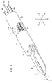
- FIG. 1 is an overall configuration diagram of a manipulator system according to an embodiment of the present invention. It is a partial cross section side view of a manipulator in the state where a work part and an operation part were separated. It is a partially omitted cross-sectional plan view of a working part. It is a perspective view of a front-end
- FIG. 5 is a partially omitted perspective view of a composite input unit and its peripheral part. It is a front view of a console in the state where a speed display screen was displayed on a display. It is a front view of a console in the state where a memory selection screen was displayed on a display.
- FIG. 11A is an explanatory diagram illustrating an example of an image that prompts connection of the operation unit to the connector
- FIG. 11B is an explanatory diagram illustrating an example of an image that prompts the user to attach the working unit to the operation unit.
- FIG. 12A is an explanatory diagram illustrating an example of an initial speed display screen
- FIG. 12B is an explanatory diagram illustrating an example of a memory selection screen.
- FIG. 13A is an explanatory diagram showing an example of a speed display screen when the speed of the distal end working unit is changed during use, and FIG.
- FIG. 13B shows a registration destination memory selection screen displayed following the screen shown in FIG. 13A
- FIG. 14A is an explanatory diagram illustrating an example of a speed display screen in a state in which a manipulator having the same type of tip operating unit is connected to each connector
- FIG. 14B is a diagram illustrating a manipulator having the same type of tip operating unit connected to each connector.
- It is explanatory drawing which shows an example of the selection screen of the manipulator which registers the setting speed after a change after using it in the state connected to. It is a schematic perspective view of a surgical robot system.
- a manipulator system (medical manipulator system) 10 includes a manipulator (medical manipulator) 11 and a console (controller) that drives and controls the manipulator 11. 29.
- the manipulator 11 operates a distal end working unit 12 provided at the distal end of the shaft 18 to perform a predetermined treatment such as gripping a part of a living body or a curved needle or cutting a part of the living body. It is.
- the width direction in FIG. 1 is defined as the X direction
- the height direction is defined as the Y direction
- the extending direction of the shaft 18 is defined as the Z direction.
- the right side is defined as the X1 direction
- the left side is defined as the X2 direction
- the upward direction is defined as the Y1 direction
- the downward direction is defined as the Y2 direction
- the front side of the shaft 18 is defined as the Z1 direction.
- the description of these directions is based on the case where the manipulator 11 is in the reference posture (neutral posture). These directions are for convenience of explanation, and it is needless to say that the manipulator 11 can be used in any direction (for example, upside down).
- the manipulator 11 is gripped and operated by a hand, and also includes an operation unit (main body unit) 14 that houses a drive mechanism 30 that applies a driving force to the distal end operation unit 12, and a work unit that is detachable from the operation unit 14. (Manipulator) 16, and a cable 28 extending from the lower end of the grip handle 26 is connected to the console 29 to constitute the manipulator system 10.
- the operation unit 14 is configured in a substantially L shape extending in the Z1 direction and the Y2 direction, and a pair of upper covers 25a and 25b (substantially divided in the Z direction).
- a grip handle 26 in which the drive mechanism 30 and the like are housed inside the housing, and the portion extending in the Y2 direction on the base end side is gripped by a hand. It is configured.
- the grip handle 26 has a length suitable for being manually gripped, and a composite input section (input section) 24 is provided on the upper inclined surface 26a.
- a master switch 34 is provided that is exposed from the upper cover 25b, and an LED 35 is provided at a location that is easily visible in the Z1 direction of the master switch 34.
- an electrode plug 41 extending in the Y1 direction from the vicinity of the end of the operation unit 14 in the Z1 direction is an electrode to which a high voltage power source is connected when the manipulator 11 is used as an electric knife. A voltage can be supplied to the distal end working unit 12 side.
- the working unit 16 includes a distal end working unit 12 for performing work, a long and hollow shaft 18 provided with the distal end working unit 12 at the distal end, and a proximal end side of the shaft 18.
- a pulley box 32 to be fixed and a trigger lever 36 pivotally supported by a trigger lever support portion 33 extending from the Z2 direction end of the pulley box 32 are provided.
- the working unit 16 has a pair of lower covers 37a and 37b (hereinafter, collectively referred to as “lower cover 37”) divided substantially symmetrically in the Z direction as a casing, and houses a pulley box 32 therein.
- the trigger lever support portion 33 is a pair of plates extending in parallel with the Z2 direction from the Z2 side end surface of the pulley box 32, and the trigger lever 36 is pivotally supported by a trigger shaft 39 extending between the plates. (See FIG. 3).
- the distal end working unit 12 and the shaft 18 are configured to have a small diameter, and can be inserted into a body cavity 22 from a cylindrical trocar 20 provided in a patient's abdomen or the like.
- various procedures such as excision of the affected area, grasping, suturing and ligation can be performed in the body cavity 22.
- the distal end working unit 12 that operates based on the operation of the composite input unit 24 and the trigger lever 36 includes, for example, a collar 48, a yaw axis Oy operation that tilts with respect to the Y axis, and directs the tip.
- a three-axis operation including a roll axis Or operation that rotates with respect to the axis (Z axis in the neutral posture) and an open / close axis Oo operation that opens and closes the collar 48 is possible.
- the yaw axis Oy and the roll axis Or are electrically driven based on the operation of the composite input unit 24, and the opening / closing axis Oo is mechanically driven based on the operation of the trigger lever 36.
- a pitch axis operation that swings the tip operation unit 12 up and down may be applied together with or instead of the yaw axis Oy.
- mechanical is a system driven through wires, chains, timing belts, links, rods, gears, etc., and is a system driven mainly through solid mechanical parts that are inelastic in the power transmission direction. is there. Wires, chains, and the like may inevitably have some elongation due to tension, but these are inelastic solid mechanical parts.
- Such a working unit 16 is connected and fixed to the operation unit 14 by a pair of left and right attachment / detachment levers 40, 40 provided in the operation unit 14, and can be separated from the operation unit 14 by an opening operation of the attachment / detachment lever 40.
- the replacement operation can be easily performed at the operation site without using a special instrument.
- the manipulator 11 and the manipulator system 10 including the manipulator 11 can selectively adopt various configurations.
- the working unit 16 that can be attached to and detached from the operation unit 14 includes five types of working units 16a, 16b, 16c, 16d, and 16e in which the type of the distal end working unit 12 is changed.
- the console 29 can be connected to two manipulators 11 simultaneously. That is, the console 29 is provided with the first connector 100 and the second connector 102, and one operation unit 14 can be attached to each connector 100, 102. Furthermore, for example, a desired working unit among the above-described five types of working units 16a to 16e can be attached to each operation unit. Thus, the operator uses two manipulators at the same time according to the type and familiarity of the procedure, and configures the manipulator system 10 by selectively combining various working units 16a to 16d as the working unit 16. Can do.
- Examples of the type of the distal end working unit 12 include a scissors, a gripper, a needle driver (gripping forceps), an electric knife, a blade type electric knife, and a hook type electric knife.
- Each of the working parts 16a to 16d provided with these various distal end working parts 12 has a common configuration from the shaft 18 including the pulley box 32 and the like to the trigger lever 36. Can be supplied to the operation unit 14 side, that is, the console 29.
- the drive mechanism 30 includes two motors (actuators) 50a and 50b arranged in the X direction, a bracket 52 that supports the motors 50a and 50b, and the rotational directions of the motors 50a and 50b. And a gear mechanism unit 54 that converts the signal and transmits it to the working unit 16 side.
- the motors 50a and 50b are cylindrical, and output shafts 56a and 56b that are decelerated by a reduction gear (not shown) pass through one surface of the bracket 52, and a drive umbrella that constitutes a gear mechanism portion 54 with respect to the output shafts 56a and 56b. Gears 58a and 58b are fixed.
- the motors 50a and 50b are, for example, DC motors, and a rotary encoder or the like is provided as an angle sensor (not shown).
- the gear mechanism portion 54 is provided in a space in the bracket 52, and is fixed to the two drive shafts (drive shafts) 60a and 60b arranged in the X direction, and the drive shafts 60a and 60b, and the drive bevel gears 58a and 58b. And two driven bevel gears 62a and 62b that mesh with each other.
- the output shafts 56a and 56b of the motors 50a and 50b, the drive shafts 60a and 60b, and the like are pivotally supported on the bracket 52 by bearings (not shown).
- the lower end side of the drive shaft 60a (60b) protrudes from the lower surface of the bracket 52, and an engagement convex portion 64a (64b) having a tapered taper shape with a corrugated hexagonal cross section, for example, is provided at the tip thereof (see FIG. (See FIG. 2).
- the pulley box 32 includes a hollow portion 66 opened on both sides in the X direction, pulleys (driven shafts) 70a and 70b and wire guide portions 72a and 72b housed in the hollow portion 66.
- the shaft 18 is fixed and supported by a hole that penetrates the cavity 66 on the Z1 side.
- a barcode (working unit identification information recording unit) 75 is provided facing upward.
- the barcode 75 is, for example, a two-dimensional barcode, is read by a camera (reading unit) 77 provided on the operation unit 14 side, and supplies identification information such as the type of the working unit 16 to the console 29. Is.
- the pulleys 70a and 70b are coaxial with respect to the drive shafts 60a and 60b, and engagement concave portions 74a and 74b that can be engaged with the engagement convex portions 64a and 64b on the drive shafts 60a and 60b side are provided on the upper ends thereof. Is provided.
- the engagement recesses 74a and 74b can be engaged (fitted) with the engagement protrusions 64a and 64b, and have, for example, a recess having a tapered wavy shape with a corrugated cross section (see FIG. 2).
- the operation unit 14 includes, for example, an attachment / detachment detection sensor (not shown) that detects attachment / detachment of the operation unit 14 and the working unit 16 and a phase detection sensor (not shown) that detects the phase of the drive shaft 60a.
- the engagement structure of the engagement convex part 64a and the engagement concave part 74a may be another structure.
- the wire guide portion 72a (72b) is disposed on the Z1 side of the pulley 70a (70b), and the interval between the wire guide portions 72a (72b) is set narrow. And guides the wire (power transmission member) 80a (80b) wound between the gear 78 and the gear 79 of the distal end working unit 12 (see FIG. 4) and smoothly guides them into the shaft 18.
- the shaft 18 can be made sufficiently thin without depending on the diameters of the motors 50a and 50b and the inter-axis distances of the pulleys 70a and 70b. Can be easily set to an outer diameter of about 5 mm to 10 mm, which is suitable for being inserted into the housing.
- two rods 82a and 82b which are rod-shaped or linear power transmission members, are further aligned in the Y direction and penetrated in the Z direction.
- the rods 82a and 82b are, for example, sufficiently strong and thin stainless steel pipes or solid rods, and extend in the Z1 direction through the hollow portion 66 into the shaft 18 and in the distal end working portion 12 via a wire or the like (not shown).
- the Z2 direction extends through the pulley box 32 to the trigger lever support 33, and is connected to the trigger lever 36 via a wire (not shown). (See FIG. 3).
- a pair of pin holes 84, 84 that are symmetrical with respect to the Z direction are formed on the Z2 side of the pulley box 32.
- a pair of guide pins 86, 86 projecting from the bottom surface of the bracket 52 in the Y1 direction are inserted into the pin holes 84, 84 when the working unit 16 and the operating unit 14 are mounted.
- the part 16 is positioned and mounted with high rigidity.
- the wires 80a and 80b reciprocate between the pulleys 70a and 70b side and the distal end working unit 12 side, respectively, so that a total of four wires 80a, 80b and the two rods 82a and 82b are inserted.
- all power transmission mechanisms may be configured with only wires instead of rods.
- the wires 80a and 80b may be of the same type, different types, the same diameter, or different diameters, and are made of a flexible bendable wire.
- portions that pass through the shaft 18 and do not require flexibility may be reinforced by surrounding a high-rigidity reinforcing rod (not shown).
- the motors 50a and 50b are driven and controlled under the control of the console 29, whereby the wires 80a and 50b are driven from the drive shafts 60a and 60b via the pulleys 70a and 70b.
- 80b is driven to reciprocate, and a rotation operation (roll direction operation) about the roll axis Or and a swing operation (yaw direction operation or pitch direction operation) about the yaw axis Oy are imparted to the distal end working unit 12 ( (See FIG. 4).
- the trigger lever 36 is rotated, the rods 82a and 82b are mechanically reciprocated, and an opening / closing operation is given to the collar 48 of the distal end working unit 12.
- the pulleys 70a and 70b serve as drive mechanism units that apply driving force to the wires 80a and 80b and the rods 82a and 82b, which are power transmission members, and operate the distal end operating unit 12.
- the pulleys 70a and 70b (motors 50a and 50b) function as an electric mechanism unit that applies driving force to the wires 80a and 80b, and applies operation in the roll direction and yaw direction to the distal end operating unit 12.
- the trigger lever 36 functions as a manual mechanism that applies a driving force to the rods 82 a and 82 b and applies an opening / closing operation of the rod 48 to the distal end operating unit 12.
- the composite input unit 24 for electrically driving the tip operating unit 12 has X1 and Y centered on the Z axis (Y axis). This is a composite input unit that is symmetrical with respect to the X2 direction and gives rotation commands in the roll direction (axial rotation direction) and yaw direction (left-right direction) to the distal end working unit 12.
- the composite input unit 24 is supported by a sensor holder 88 disposed on the inclined surface 26a, and is provided on the Z1 side (Y1 side) rotation operation unit 90 of the inclined surface 26a and on the Z2 side (Y2 side) thereof.
- the tilt operation unit 92 includes three switch operators 94a to 94c disposed on the lower side surface of the tilt operation unit 92, respectively.
- the operation amount of the input to the rotation operation unit 90 and the like is detected by a switch board (not shown) provided in the sensor holder 88, and the motors 50a and 50b are appropriately driven and controlled under the control of the console 29.
- console 29 is a controller (control unit) that comprehensively controls the manipulator system 10. A part of the function of the console 29 may be mounted on the operation unit 14. As shown in FIGS. 1 and 5, the console 29 includes two connectors 100 and 102, and can control the two manipulators 11 independently and simultaneously.
- the console 29 can be connected to a host computer (not shown), which is a usage history management means, via a communication means such as a LAN.
- the host computer records a use history table in an internal recording means, and uses history corresponding to individual numbers (identification numbers) requested to the console 29 or a plurality of consoles 29 connected by the LAN. Send and receive and manage data.
- the host computer is not limited to a configuration independent of the console 29, and the function may be provided in the console 29.
- the first connector 100 and the second connector 102 are provided on the front panel of the console 29 so as to be separated from each other on the left and right sides, and correspond to the two manipulators 11 connected to each of the first connectors 100 and A first setting switch S1 and a second setting switch S2 are arranged with the central display 104 interposed therebetween. That is, the first connector 100 and the first setting switch S1 become a first channel corresponding to one manipulator 11, the second connector 102 and the second setting switch S2 become a second channel corresponding to the other manipulator 11, A configuration in which the number of channels is increased depending on usage conditions or the like may be employed.
- a plurality (four in this embodiment) of function switches F1, F2, F3, F4 provided along the lower side of the display 104, and the power of the console 29 are turned ON / OFF.
- a power switch 106 that is turned off, and an error display unit 110 that lights (flashes) various system errors such as connection errors between the operation unit 14 and the work unit 16 in the manipulator 11 are provided.
- the first setting switch S ⁇ b> 1 is for changing the speed of the distal end working unit 12 of the manipulator 11 connected to the first connector 100, and a pair of left and right roll speeds provided on the upper stage. It has change buttons R1a and R1b and a pair of left and right yaw speed change buttons Y1a and Y1b provided in the lower stage.
- the roll speed change buttons R1a and R1b are setting input units for decreasing (R1a) and increasing (R1b) the rotational operation speed in the direction of the roll axis Or of the tip operating unit 12, and in between these, A mark MR1 is provided to clearly indicate that the speed change buttons R1a and R1b are switches that change the speed of the roll operation.
- the yaw speed change buttons Y1a and Y1b are setting input units for decreasing (Y1a) and increasing (Y1b) the speed of the swinging motion of the tip operating unit 12 in the yaw axis Oy direction.
- a mark MY1 is provided to clearly indicate that the yaw speed change buttons Y1a and Y1b change the speed of the yaw operation.
- the second setting switch S2 is an input unit that changes the speed of the rotation operation in the roll axis Or direction and the swing operation in the yaw axis Oy direction of the tip operation unit 12 of the manipulator 11 connected to the second connector 102. Except that, it is substantially the same as the first setting switch S1. That is, the second setting switch S2 includes a pair of left and right roll speed change buttons R2a and R2b provided on the upper stage, a pair of left and right yaw speed change buttons Y1a and Y1b, a mark MR2, and a mark MY2. .
- the operation speed of the roll axis operation and the yaw axis operation of each working unit 16 is set to, for example, “5 (fast), 4 (slightly fast), 3 (reference speed), 2 (slightly slow), and 1 (slow) ”can be set and adjusted as appropriate according to the user's preference and procedure.
- the operation management unit 118 controls driving of the motors 50a and 50b at the set operation speed, thereby controlling the operation speed of the distal end operation unit 12 to a desired speed.
- the display 104 displays the setting speeds of the roll axis operation and the yaw axis operation by the first setting switch S1 and the second setting switch S2 in an arrangement corresponding to each setting switch S1, S2. Can do.
- the display 104 can display information of each manipulator 11 connected to the first connector 100 and the second connector 102 on the left and right sides of the screen, respectively, and the type of the working unit 16 (tip operation unit 12) on the upper stage.
- the console 29 can drive and control two manipulators individually and simultaneously, for example, the operation speed of the first setting switch S1 constituting the first channel and the manipulator 11 corresponding to the first setting switch can be expressed in numbers and graphs.
- the display on the left half of the middle stage of the display 104 is configured to be surrounded by the same color, and the display on the right half of the middle stage of the display 104 displaying the second setting switch S2 and its set value in a color different from this color. If it encloses, the operation speed setting of each manipulator 11 and its setting change will become easier.
- the console 29 corresponds to, for example, the five types of tip operation units 12 (working unit 16) as described above, and a plurality of set speeds (for example, roll axis operation and yaw axis operation of the five types of tip operation units 12 (for example, 8 users) can be set and stored individually according to the preferences of the users (doctors).
- a plurality of set speeds for example, roll axis operation and yaw axis operation of the five types of tip operation units 12 (for example, 8 users) can be set and stored individually according to the preferences of the users (doctors).
- the display 104 can also collectively display the set speeds of the roll axis operation and the yaw axis operation that are set and stored for each type of the tip operation unit 12.
- the display 104 displays, for example, memories A, B, C, D, E, F, G, and H, which are individual set speed folders for each of eight users, in the upper row, and the currently selected memory name.
- memories A, B, C, D, E, F, G, and H which are individual set speed folders for each of eight users, in the upper row, and the currently selected memory name.
- the speed can be displayed numerically together with the mark and name, and the current functions of the function switches F1 to F4 can be displayed in the lower part.
- the setting speed screen shown in FIG. 8 displays, for example, information on the manipulator 11 connected to the first connector 100, and then when the setting is completed, the manipulator connected to the second connector 102 automatically. 11 information is displayed.
- the function switches F1 to F4 can be provided with buttons for selecting whether to display the information of the manipulator 11 connected to which of the first and second connectors 100 and 102.
- FIG. 8 five types of the tip moving parts 12 are arranged in order from the left: needle driver (Needle Driver), monopolar L hook (Monopolar L Hook), spider (Scissors), needle driver (Needle Driver), bipolar glass spar ( The case where Bipolar Grasper) is used is illustrated.
- a needle driver (Needle Driver) is connected to the first connector 100
- a monopolar L hook (Monopolar L Hook) is connected to the second connector 102
- M setting information of the memory B
- FIG. 9 is a block diagram for explaining functions of the console 29.
- the console 29 includes the power switch 106, the setting switches S1 and S2, the function switches F1 to F4, the display 104, the error display unit 110, and the connectors 100 and 102. And a system control unit 112 and a storage unit 114.
- the system control unit 112 is a comprehensive control unit of the console 29 including a language setting unit 116, an operation management unit 118, and a display control unit 120.
- the language setting unit 116 sets a language (for example, Japanese, English, Chinese, French, Spanish) displayed and used on the console 29 by, for example, initial setting at the first activation or arbitrary setting change.
- the setting is stored in the storage unit 114, and thereafter, the display is displayed on the display 104 corresponding to the set language (or changed language), and the console 29 can be operated.
- the operation management unit 118 detects the operation unit 14 that is a handle connected to the connectors 100 and 102, and the item that detects the work unit 16 that is an item attached to the handle (operation unit 14).
- a data management unit 128 that manages various types of data such as identification information (individual number, type of tip operation unit 12, etc.) of the working unit 16 that is read by photographing, using the storage unit 114.
- the display control unit 120 receives supply of various types of information from the operation management unit 118, calculates the information, and displays the information on the display 104. In addition, display processing for function information distributed to the function switches F1 to F4 is also performed.
- the storage unit 114 is a memory (for example, a RAM) that stores the language set in the language setting unit 116, the set speed information of the roll axis operation and the yaw axis operation set and stored for each type of the tip operation unit 12, and the like. is there. As shown in FIG. 10, in the case of the present embodiment, the storage unit 114 can register eight sets of set speed information of the roll axis operation and the yaw axis operation in the memories A to H. The set speed information of five types of items 1 to 5 can be registered per group.
- the connector of the operation unit 14 as a handle is displayed on the display 104 under the control of the operation management unit 118 and the display control unit 120, as shown in FIG. 11A.
- An image prompting connection to 100, 102 is displayed.
- the connection is detected by the handle detection unit 122, and as shown in FIG. 11B, an image that prompts the user to attach the work unit 16 that is an item to the operation unit 14 is displayed.
- the mounting is detected by the item detection unit 124.
- the left half of the screen displays an image for prompting item mounting
- the right half of the screen is an image for prompting the second connector 102 to mount a handle. Is displayed.
- the display 104 When the manipulator 11 is connected to each of the connectors 100 and 102, as shown in FIG. 12A, the display 104 has an initial speed display screen (M-0) that is a TOP screen when the memories A to H are not selected. ) Is displayed. Further, on the initial speed display screen, the type of the manipulator 11 (tip operating unit 12) connected to each connector 100, 102 is displayed based on the identification information acquired through the barcode 75 and the camera 77. For this reason, the user can move to the selection screen of the registered memories A to H as shown in FIG. 12B by selecting “Recall Memory” of the function switch F4. In this memory selection screen, a desired memory B can be selected, for example, as shown in FIG. 8 by selecting and operating the function switches F1 to F4 according to the screen instructions.
- M-0 initial speed display screen
- the type of the manipulator 11 (tip operating unit 12) connected to each connector 100, 102 is displayed based on the identification information acquired through the barcode 75 and the camera 77. For this reason,
- the setting speed information registered in the memory B according to the type of the distal end working unit 12 for the working unit 16 currently connected to the connectors 100 and 102 under the management of the data management unit 128 is stored in the storage unit 114. And displayed as shown in FIG. 7, and the preparation for use of the manipulator system 10 is completed.
- the first setting switch S1 roll speed changing buttons R1a, R1b, yaw speed changing buttons Y1a, Y1b
- the second setting switch S2 roll speed change buttons R2a, R2b, yaw speed change buttons Y2a, Y2b
- the operation speed is changed in accordance with the operation, and the numbers and graphs in FIG. 7 are also changed at the same time.
- the user can easily and accurately change the operation speed while looking at the display 104. It is possible to flexibly correspond to the optimum operation speed according to the procedure.
- the first and second setting switches S1 and S2 are arranged corresponding to the left and right first and second connectors 100 and 102, respectively, the speed change of the desired manipulator 11 out of the two manipulators 11 is performed. Can be performed more intuitively and accurately.
- the display at the middle stage of the display 104 becomes “M-0”, which is the same as the initial speed display, and “Update” is displayed on the function switch F3. Is displayed. Therefore, by selecting the function switch F3, the changed set speed can be registered in a desired memory among the memories A to H.
- the set speed after the change may be overwritten and registered in the memory called at the start of use, overwritten in another memory, or may be registered in an empty memory in which no speed information is registered. .
- the speed before the change is the roll axis operation speed of the needle driver (Needle Driver) of the item 1. “5 (fastest)”, yaw axis operation speed is “2 (slightly slow)”, and the speed after the setting is changed during use is as shown in FIG. Speed) ”, and the yaw axis operating speed is“ 4 (slightly faster) ”, as shown in FIG. 13B, the speed after the change is colored by placing an arrow to the right of the number indicating the speed before the change.
- the fonts are displayed in parallel with slightly smaller fonts.
- the user can compare the set speed information before the change with the set speed information after the change on the screen, and select the function switch F4 to which the “overwrite” function is added.
- the function switches F2, F3, etc. are appropriately operated to display the information in the other memory, and the speed information before the change and the change are displayed. What is necessary is just to perform overwriting operation, comparing with later speed information on a screen.
- FIG. 13B since the set speed information is not registered in the memory E, “empty” is displayed above the display of “E”, indicating that the memory E is an empty memory. It is clearly stated.
- Such a registration change is processed through the speed setting unit 126 of the operation management unit 118, and after the registration is completed, the speed display screen as shown in FIG. 7 again through the operation management unit 118 and the display control unit 120. Since the (TOP screen) is automatically displayed on the display 104, the user smoothly shifts to the next procedure or ends the procedure.
- the storage unit 114 of the console 29 has a specification in which only one item of the same type can be registered for one memory A to H.
- a working unit 16 having the same type of distal end working unit 12 is connected to each connector 100, 102 for use (in FIG. 14A, both two manipulators 11 are connected to the needle driver “Needle”.
- Driver " when the operating speed is changed during use, the desired setting value can be changed by displaying a selection screen as to whether or not to register the left or right setting value as shown in FIG. 14B. Registration can be changed as a later setting. That is, in FIG. 14B, a screen for registering the selected setting value by selecting one of the function switches F2 (“right”) and F3 (“left”) (registration change screen in FIG. 13B). Is substantially the same).
- the console 29 it is possible to change the information in each memory AH before starting the procedure, such as before connection of the manipulator 11, or to newly register the information.
- the function switches F1 to F4 Since the registration operation is prompted by the screen display, the user can easily perform setting registration by the display similar to the display shown in FIG. 13B. Of course, it is possible to delete registration information in the memories A to H which are not required.
- the speed setting unit 126 capable of changing the operation speed of the tip operation unit capable of rotating in the roll direction and swinging in the yaw direction (or pitch direction) is provided on the console. 29.
- the speed setting unit 126 performs speed setting by selecting the first setting switch S1 and the second setting switch S2, and therefore the speed setting unit may include setting switches S1 and S2. Good.
- the manipulator system 10 including the console 29 that controls the two manipulators 11 at the same time has been illustrated. 11 may be adopted.
- Surgical Robot System can also be applied to a surgical robot system 500 as shown in FIG. 15, for example.
- the surgical robot system 500 includes an articulated robot arm 502 and a console (controller) 504 for controlling the robot arm, and a mechanism similar to the manipulator 11 is provided at the tip of the robot arm 502. Yes.
- a base portion 14a that houses the drive mechanism 30 is fixed to the distal end portion 508 of the robot arm 502, and the working portion in which the distal end operating portion 12 is provided with respect to the base portion 14a. 16 is detachably attached.
- the robot arm 502 may be any means that moves the working unit 16, and is not limited to a stationary type, but may be an autonomous moving type, for example. If the robot arm 502 has six or more independent joints (such as a rotation axis and a slide axis), the position and orientation of the working unit 16 can be arbitrarily set.
- a base portion 14 a constituting the manipulator 11 at the tip is integrated with a tip portion 508 of the robot arm 502.
- the console 504 is provided with two joysticks 506 as an operation command unit and a monitor 510.
- the console 504 can take a configuration such as a table type or a control panel type.
- the robot arm 502 operates under the action of the console 504, and may be configured to perform automatic operation based on a program, operation following a joystick 506 provided on the console 504, and a combination of these operations.
- the console 504 includes the functions of the console 29 described above.
- the monitor 510 is provided with the same function as the display 104 (see FIG. 7), and the first and second setting switches S1 and S2 and the function switches F1 to F4 are installed around the monitor 510.
- the console 504 is equipped with a system control unit 112, a storage unit 114, and the like similar to the console 29. Further, the base portion 14a and the joystick 506 perform the same function as the operation portion (main body portion) 14 (see FIG. 1).
- the two robot arms 502 can be individually operated by the two joysticks 506. In FIG. 15, only one robot arm 502 is illustrated, but two robot arms 502 may be provided as in the manipulator system 10.
- the two joysticks 506 are provided at positions that can be easily operated with both hands.
- the joystick 506 can move up and down, move left and right, twist, and tilt, and can move the robot arm 502 according to these operations.
- the joystick 506 may be a master arm.
- the joystick 506 is provided with a grip handle 26A, a trigger lever 36A that is pushed and pulled, and a composite input unit 24A that is rotated and tilted.
- the trigger lever 36A is an alternative to the trigger lever 36, and by operating the trigger lever 36A, two rods 82a, 82b (see FIG. 3; not shown in FIG. 15) can be driven back and forth.
- the composite input unit 24A is an alternative to the composite input unit 24 described above.
- the drive mechanism 30 is controlled by the console 504 according to the operation content. A roll operation, a tilting operation, or a combined operation thereof is performed.
- the first setting switch S1 and the like provided on the console 504 the operating speed of the distal end working unit 12 can be changed and registered as in the manipulator system 10.
- the communication means between the robot arm 502 and the console 504 may be wired, wireless, network, or a combination thereof.
- On the monitor 510 information such as an image by a flexible endoscope is displayed.
Landscapes
- Health & Medical Sciences (AREA)
- Engineering & Computer Science (AREA)
- Life Sciences & Earth Sciences (AREA)
- Surgery (AREA)
- Heart & Thoracic Surgery (AREA)
- Animal Behavior & Ethology (AREA)
- Nuclear Medicine, Radiotherapy & Molecular Imaging (AREA)
- Veterinary Medicine (AREA)
- Public Health (AREA)
- Biomedical Technology (AREA)
- General Health & Medical Sciences (AREA)
- Medical Informatics (AREA)
- Molecular Biology (AREA)
- Robotics (AREA)
- Physics & Mathematics (AREA)
- General Physics & Mathematics (AREA)
- Automation & Control Theory (AREA)
- Dentistry (AREA)
- Oral & Maxillofacial Surgery (AREA)
- Orthopedic Medicine & Surgery (AREA)
- Manipulator (AREA)
- Surgical Instruments (AREA)
Priority Applications (4)
| Application Number | Priority Date | Filing Date | Title |
|---|---|---|---|
| JP2012508271A JP5758882B2 (ja) | 2010-03-30 | 2011-03-28 | 医療用マニピュレータシステム |
| EP11762740.6A EP2554128B1 (en) | 2010-03-30 | 2011-03-28 | Medical manipulator system |
| CN201180017198.9A CN102834064B (zh) | 2010-03-30 | 2011-03-28 | 医疗用操纵系统 |
| US13/626,112 US9414849B2 (en) | 2010-03-30 | 2012-09-25 | Medical manipulator system |
Applications Claiming Priority (2)
| Application Number | Priority Date | Filing Date | Title |
|---|---|---|---|
| JP2010-076940 | 2010-03-30 | ||
| JP2010076940 | 2010-03-30 |
Related Child Applications (1)
| Application Number | Title | Priority Date | Filing Date |
|---|---|---|---|
| US13/626,112 Continuation US9414849B2 (en) | 2010-03-30 | 2012-09-25 | Medical manipulator system |
Publications (1)
| Publication Number | Publication Date |
|---|---|
| WO2011122516A1 true WO2011122516A1 (ja) | 2011-10-06 |
Family
ID=44712213
Family Applications (1)
| Application Number | Title | Priority Date | Filing Date |
|---|---|---|---|
| PCT/JP2011/057526 WO2011122516A1 (ja) | 2010-03-30 | 2011-03-28 | 医療用マニピュレータシステム |
Country Status (5)
| Country | Link |
|---|---|
| US (1) | US9414849B2 (zh) |
| EP (1) | EP2554128B1 (zh) |
| JP (1) | JP5758882B2 (zh) |
| CN (1) | CN102834064B (zh) |
| WO (1) | WO2011122516A1 (zh) |
Cited By (5)
| Publication number | Priority date | Publication date | Assignee | Title |
|---|---|---|---|---|
| CN104080417A (zh) * | 2012-08-31 | 2014-10-01 | 奥林巴斯医疗株式会社 | 超声波手术系统 |
| JP2017064878A (ja) * | 2015-10-02 | 2017-04-06 | ファナック株式会社 | ロボットを操作するハンドルを備えたロボット用操作装置 |
| JP2019072811A (ja) * | 2017-10-17 | 2019-05-16 | 株式会社マキタ | 電動作業機 |
| JP2020534951A (ja) * | 2017-09-29 | 2020-12-03 | エシコン エルエルシーEthicon LLC | 外科用器具の言語選択のためのシステム及び方法 |
| US10881475B2 (en) | 2015-07-09 | 2021-01-05 | Kawasaki Jukogyo Kabushiki Kaisha | Surgical robot |
Families Citing this family (422)
| Publication number | Priority date | Publication date | Assignee | Title |
|---|---|---|---|---|
| US9060770B2 (en) | 2003-05-20 | 2015-06-23 | Ethicon Endo-Surgery, Inc. | Robotically-driven surgical instrument with E-beam driver |
| US20070084897A1 (en) | 2003-05-20 | 2007-04-19 | Shelton Frederick E Iv | Articulating surgical stapling instrument incorporating a two-piece e-beam firing mechanism |
| US8215531B2 (en) | 2004-07-28 | 2012-07-10 | Ethicon Endo-Surgery, Inc. | Surgical stapling instrument having a medical substance dispenser |
| US11896225B2 (en) | 2004-07-28 | 2024-02-13 | Cilag Gmbh International | Staple cartridge comprising a pan |
| US11246590B2 (en) | 2005-08-31 | 2022-02-15 | Cilag Gmbh International | Staple cartridge including staple drivers having different unfired heights |
| US11484312B2 (en) | 2005-08-31 | 2022-11-01 | Cilag Gmbh International | Staple cartridge comprising a staple driver arrangement |
| US7934630B2 (en) | 2005-08-31 | 2011-05-03 | Ethicon Endo-Surgery, Inc. | Staple cartridges for forming staples having differing formed staple heights |
| US7669746B2 (en) | 2005-08-31 | 2010-03-02 | Ethicon Endo-Surgery, Inc. | Staple cartridges for forming staples having differing formed staple heights |
| US10159482B2 (en) | 2005-08-31 | 2018-12-25 | Ethicon Llc | Fastener cartridge assembly comprising a fixed anvil and different staple heights |
| US9237891B2 (en) | 2005-08-31 | 2016-01-19 | Ethicon Endo-Surgery, Inc. | Robotically-controlled surgical stapling devices that produce formed staples having different lengths |
| US20070106317A1 (en) | 2005-11-09 | 2007-05-10 | Shelton Frederick E Iv | Hydraulically and electrically actuated articulation joints for surgical instruments |
| US8186555B2 (en) | 2006-01-31 | 2012-05-29 | Ethicon Endo-Surgery, Inc. | Motor-driven surgical cutting and fastening instrument with mechanical closure system |
| US20110295295A1 (en) | 2006-01-31 | 2011-12-01 | Ethicon Endo-Surgery, Inc. | Robotically-controlled surgical instrument having recording capabilities |
| US20110024477A1 (en) | 2009-02-06 | 2011-02-03 | Hall Steven G | Driven Surgical Stapler Improvements |
| US7753904B2 (en) | 2006-01-31 | 2010-07-13 | Ethicon Endo-Surgery, Inc. | Endoscopic surgical instrument with a handle that can articulate with respect to the shaft |
| US11278279B2 (en) | 2006-01-31 | 2022-03-22 | Cilag Gmbh International | Surgical instrument assembly |
| US11224427B2 (en) | 2006-01-31 | 2022-01-18 | Cilag Gmbh International | Surgical stapling system including a console and retraction assembly |
| US20120292367A1 (en) | 2006-01-31 | 2012-11-22 | Ethicon Endo-Surgery, Inc. | Robotically-controlled end effector |
| US11793518B2 (en) | 2006-01-31 | 2023-10-24 | Cilag Gmbh International | Powered surgical instruments with firing system lockout arrangements |
| US8820603B2 (en) | 2006-01-31 | 2014-09-02 | Ethicon Endo-Surgery, Inc. | Accessing data stored in a memory of a surgical instrument |
| US8708213B2 (en) | 2006-01-31 | 2014-04-29 | Ethicon Endo-Surgery, Inc. | Surgical instrument having a feedback system |
| US7845537B2 (en) | 2006-01-31 | 2010-12-07 | Ethicon Endo-Surgery, Inc. | Surgical instrument having recording capabilities |
| US8992422B2 (en) | 2006-03-23 | 2015-03-31 | Ethicon Endo-Surgery, Inc. | Robotically-controlled endoscopic accessory channel |
| US8322455B2 (en) | 2006-06-27 | 2012-12-04 | Ethicon Endo-Surgery, Inc. | Manually driven surgical cutting and fastening instrument |
| US8220690B2 (en) | 2006-09-29 | 2012-07-17 | Ethicon Endo-Surgery, Inc. | Connected surgical staples and stapling instruments for deploying the same |
| US10568652B2 (en) | 2006-09-29 | 2020-02-25 | Ethicon Llc | Surgical staples having attached drivers of different heights and stapling instruments for deploying the same |
| US11980366B2 (en) | 2006-10-03 | 2024-05-14 | Cilag Gmbh International | Surgical instrument |
| US11291441B2 (en) | 2007-01-10 | 2022-04-05 | Cilag Gmbh International | Surgical instrument with wireless communication between control unit and remote sensor |
| US8652120B2 (en) | 2007-01-10 | 2014-02-18 | Ethicon Endo-Surgery, Inc. | Surgical instrument with wireless communication between control unit and sensor transponders |
| US8684253B2 (en) | 2007-01-10 | 2014-04-01 | Ethicon Endo-Surgery, Inc. | Surgical instrument with wireless communication between a control unit of a robotic system and remote sensor |
| US20080169332A1 (en) | 2007-01-11 | 2008-07-17 | Shelton Frederick E | Surgical stapling device with a curved cutting member |
| US11039836B2 (en) | 2007-01-11 | 2021-06-22 | Cilag Gmbh International | Staple cartridge for use with a surgical stapling instrument |
| US20090001130A1 (en) | 2007-03-15 | 2009-01-01 | Hess Christopher J | Surgical procedure using a cutting and stapling instrument having releasable staple-forming pockets |
| US8893946B2 (en) | 2007-03-28 | 2014-11-25 | Ethicon Endo-Surgery, Inc. | Laparoscopic tissue thickness and clamp load measuring devices |
| US11857181B2 (en) | 2007-06-04 | 2024-01-02 | Cilag Gmbh International | Robotically-controlled shaft based rotary drive systems for surgical instruments |
| US8931682B2 (en) | 2007-06-04 | 2015-01-13 | Ethicon Endo-Surgery, Inc. | Robotically-controlled shaft based rotary drive systems for surgical instruments |
| US7753245B2 (en) | 2007-06-22 | 2010-07-13 | Ethicon Endo-Surgery, Inc. | Surgical stapling instruments |
| US11849941B2 (en) | 2007-06-29 | 2023-12-26 | Cilag Gmbh International | Staple cartridge having staple cavities extending at a transverse angle relative to a longitudinal cartridge axis |
| US8573465B2 (en) | 2008-02-14 | 2013-11-05 | Ethicon Endo-Surgery, Inc. | Robotically-controlled surgical end effector system with rotary actuated closure systems |
| US8636736B2 (en) | 2008-02-14 | 2014-01-28 | Ethicon Endo-Surgery, Inc. | Motorized surgical cutting and fastening instrument |
| US7866527B2 (en) | 2008-02-14 | 2011-01-11 | Ethicon Endo-Surgery, Inc. | Surgical stapling apparatus with interlockable firing system |
| BRPI0901282A2 (pt) | 2008-02-14 | 2009-11-17 | Ethicon Endo Surgery Inc | instrumento cirúrgico de corte e fixação dotado de eletrodos de rf |
| US8758391B2 (en) | 2008-02-14 | 2014-06-24 | Ethicon Endo-Surgery, Inc. | Interchangeable tools for surgical instruments |
| US9179912B2 (en) | 2008-02-14 | 2015-11-10 | Ethicon Endo-Surgery, Inc. | Robotically-controlled motorized surgical cutting and fastening instrument |
| US11986183B2 (en) | 2008-02-14 | 2024-05-21 | Cilag Gmbh International | Surgical cutting and fastening instrument comprising a plurality of sensors to measure an electrical parameter |
| US7819298B2 (en) | 2008-02-14 | 2010-10-26 | Ethicon Endo-Surgery, Inc. | Surgical stapling apparatus with control features operable with one hand |
| US11272927B2 (en) | 2008-02-15 | 2022-03-15 | Cilag Gmbh International | Layer arrangements for surgical staple cartridges |
| US9615826B2 (en) | 2010-09-30 | 2017-04-11 | Ethicon Endo-Surgery, Llc | Multiple thickness implantable layers for surgical stapling devices |
| US9005230B2 (en) | 2008-09-23 | 2015-04-14 | Ethicon Endo-Surgery, Inc. | Motorized surgical instrument |
| US8210411B2 (en) | 2008-09-23 | 2012-07-03 | Ethicon Endo-Surgery, Inc. | Motor-driven surgical cutting instrument |
| US9386983B2 (en) | 2008-09-23 | 2016-07-12 | Ethicon Endo-Surgery, Llc | Robotically-controlled motorized surgical instrument |
| US11648005B2 (en) | 2008-09-23 | 2023-05-16 | Cilag Gmbh International | Robotically-controlled motorized surgical instrument with an end effector |
| US8608045B2 (en) | 2008-10-10 | 2013-12-17 | Ethicon Endo-Sugery, Inc. | Powered surgical cutting and stapling apparatus with manually retractable firing system |
| US8517239B2 (en) | 2009-02-05 | 2013-08-27 | Ethicon Endo-Surgery, Inc. | Surgical stapling instrument comprising a magnetic element driver |
| US8444036B2 (en) | 2009-02-06 | 2013-05-21 | Ethicon Endo-Surgery, Inc. | Motor driven surgical fastener device with mechanisms for adjusting a tissue gap within the end effector |
| EP2393430A1 (en) | 2009-02-06 | 2011-12-14 | Ethicon Endo-Surgery, Inc. | Driven surgical stapler improvements |
| US8551078B2 (en) * | 2009-12-04 | 2013-10-08 | Covidien Lp | Laparoscopic scaffold assembly |
| US8851354B2 (en) | 2009-12-24 | 2014-10-07 | Ethicon Endo-Surgery, Inc. | Surgical cutting instrument that analyzes tissue thickness |
| US8220688B2 (en) | 2009-12-24 | 2012-07-17 | Ethicon Endo-Surgery, Inc. | Motor-driven surgical cutting instrument with electric actuator directional control assembly |
| US8783543B2 (en) | 2010-07-30 | 2014-07-22 | Ethicon Endo-Surgery, Inc. | Tissue acquisition arrangements and methods for surgical stapling devices |
| US10945731B2 (en) | 2010-09-30 | 2021-03-16 | Ethicon Llc | Tissue thickness compensator comprising controlled release and expansion |
| US9629814B2 (en) | 2010-09-30 | 2017-04-25 | Ethicon Endo-Surgery, Llc | Tissue thickness compensator configured to redistribute compressive forces |
| US9282962B2 (en) | 2010-09-30 | 2016-03-15 | Ethicon Endo-Surgery, Llc | Adhesive film laminate |
| US11812965B2 (en) | 2010-09-30 | 2023-11-14 | Cilag Gmbh International | Layer of material for a surgical end effector |
| US8746535B2 (en) | 2010-09-30 | 2014-06-10 | Ethicon Endo-Surgery, Inc. | Tissue thickness compensator comprising detachable portions |
| US9211120B2 (en) | 2011-04-29 | 2015-12-15 | Ethicon Endo-Surgery, Inc. | Tissue thickness compensator comprising a plurality of medicaments |
| US9517063B2 (en) | 2012-03-28 | 2016-12-13 | Ethicon Endo-Surgery, Llc | Movable member for use with a tissue thickness compensator |
| US9320523B2 (en) | 2012-03-28 | 2016-04-26 | Ethicon Endo-Surgery, Llc | Tissue thickness compensator comprising tissue ingrowth features |
| US11925354B2 (en) | 2010-09-30 | 2024-03-12 | Cilag Gmbh International | Staple cartridge comprising staples positioned within a compressible portion thereof |
| US11298125B2 (en) | 2010-09-30 | 2022-04-12 | Cilag Gmbh International | Tissue stapler having a thickness compensator |
| US9364233B2 (en) | 2010-09-30 | 2016-06-14 | Ethicon Endo-Surgery, Llc | Tissue thickness compensators for circular surgical staplers |
| US8695866B2 (en) | 2010-10-01 | 2014-04-15 | Ethicon Endo-Surgery, Inc. | Surgical instrument having a power control circuit |
| JP6026509B2 (ja) | 2011-04-29 | 2016-11-16 | エシコン・エンド−サージェリィ・インコーポレイテッドEthicon Endo−Surgery,Inc. | ステープルカートリッジ自体の圧縮可能部分内に配置されたステープルを含むステープルカートリッジ |
| US11207064B2 (en) | 2011-05-27 | 2021-12-28 | Cilag Gmbh International | Automated end effector component reloading system for use with a robotic system |
| US9072535B2 (en) | 2011-05-27 | 2015-07-07 | Ethicon Endo-Surgery, Inc. | Surgical stapling instruments with rotatable staple deployment arrangements |
| US9044230B2 (en) | 2012-02-13 | 2015-06-02 | Ethicon Endo-Surgery, Inc. | Surgical cutting and fastening instrument with apparatus for determining cartridge and firing motion status |
| JP6224070B2 (ja) | 2012-03-28 | 2017-11-01 | エシコン・エンド−サージェリィ・インコーポレイテッドEthicon Endo−Surgery,Inc. | 組織厚さコンペンセータを含む保持具アセンブリ |
| BR112014024102B1 (pt) | 2012-03-28 | 2022-03-03 | Ethicon Endo-Surgery, Inc | Conjunto de cartucho de prendedores para um instrumento cirúrgico, e conjunto de atuador de extremidade para um instrumento cirúrgico |
| BR112014024098B1 (pt) | 2012-03-28 | 2021-05-25 | Ethicon Endo-Surgery, Inc. | cartucho de grampos |
| US9101358B2 (en) | 2012-06-15 | 2015-08-11 | Ethicon Endo-Surgery, Inc. | Articulatable surgical instrument comprising a firing drive |
| BR112014032776B1 (pt) | 2012-06-28 | 2021-09-08 | Ethicon Endo-Surgery, Inc | Sistema de instrumento cirúrgico e kit cirúrgico para uso com um sistema de instrumento cirúrgico |
| US11197671B2 (en) | 2012-06-28 | 2021-12-14 | Cilag Gmbh International | Stapling assembly comprising a lockout |
| US9282974B2 (en) | 2012-06-28 | 2016-03-15 | Ethicon Endo-Surgery, Llc | Empty clip cartridge lockout |
| US9204879B2 (en) | 2012-06-28 | 2015-12-08 | Ethicon Endo-Surgery, Inc. | Flexible drive member |
| US20140001231A1 (en) | 2012-06-28 | 2014-01-02 | Ethicon Endo-Surgery, Inc. | Firing system lockout arrangements for surgical instruments |
| US9364230B2 (en) | 2012-06-28 | 2016-06-14 | Ethicon Endo-Surgery, Llc | Surgical stapling instruments with rotary joint assemblies |
| RU2636861C2 (ru) | 2012-06-28 | 2017-11-28 | Этикон Эндо-Серджери, Инк. | Блокировка пустой кассеты с клипсами |
| US9289256B2 (en) | 2012-06-28 | 2016-03-22 | Ethicon Endo-Surgery, Llc | Surgical end effectors having angled tissue-contacting surfaces |
| US9700310B2 (en) | 2013-08-23 | 2017-07-11 | Ethicon Llc | Firing member retraction devices for powered surgical instruments |
| US20140207124A1 (en) | 2013-01-23 | 2014-07-24 | Ethicon Endo-Surgery, Inc. | Surgical instrument with selectable integral or external power source |
| RU2672520C2 (ru) | 2013-03-01 | 2018-11-15 | Этикон Эндо-Серджери, Инк. | Шарнирно поворачиваемые хирургические инструменты с проводящими путями для передачи сигналов |
| JP6345707B2 (ja) | 2013-03-01 | 2018-06-20 | エシコン・エンド−サージェリィ・インコーポレイテッドEthicon Endo−Surgery,Inc. | ソフトストップを備えた外科用器具 |
| US9351727B2 (en) | 2013-03-14 | 2016-05-31 | Ethicon Endo-Surgery, Llc | Drive train control arrangements for modular surgical instruments |
| US9629629B2 (en) | 2013-03-14 | 2017-04-25 | Ethicon Endo-Surgey, LLC | Control systems for surgical instruments |
| BR112015026109B1 (pt) | 2013-04-16 | 2022-02-22 | Ethicon Endo-Surgery, Inc | Instrumento cirúrgico |
| US9801626B2 (en) | 2013-04-16 | 2017-10-31 | Ethicon Llc | Modular motor driven surgical instruments with alignment features for aligning rotary drive shafts with surgical end effector shafts |
| JP6416260B2 (ja) | 2013-08-23 | 2018-10-31 | エシコン エルエルシー | 動力付き外科用器具のための発射部材後退装置 |
| USD777326S1 (en) * | 2013-12-23 | 2017-01-24 | Kaiser Medical Technology Limited | Surgical tool |
| US9962161B2 (en) | 2014-02-12 | 2018-05-08 | Ethicon Llc | Deliverable surgical instrument |
| JP6462004B2 (ja) | 2014-02-24 | 2019-01-30 | エシコン エルエルシー | 発射部材ロックアウトを備える締結システム |
| US9743929B2 (en) | 2014-03-26 | 2017-08-29 | Ethicon Llc | Modular powered surgical instrument with detachable shaft assemblies |
| US20150272557A1 (en) | 2014-03-26 | 2015-10-01 | Ethicon Endo-Surgery, Inc. | Modular surgical instrument system |
| US9690362B2 (en) | 2014-03-26 | 2017-06-27 | Ethicon Llc | Surgical instrument control circuit having a safety processor |
| JP6361213B2 (ja) * | 2014-03-26 | 2018-07-25 | セイコーエプソン株式会社 | ロボット制御装置、ロボット、ロボットシステム、教示方法、及びプログラム |
| BR112016021943B1 (pt) | 2014-03-26 | 2022-06-14 | Ethicon Endo-Surgery, Llc | Instrumento cirúrgico para uso por um operador em um procedimento cirúrgico |
| CN106456176B (zh) | 2014-04-16 | 2019-06-28 | 伊西康内外科有限责任公司 | 包括具有不同构型的延伸部的紧固件仓 |
| CN106456158B (zh) | 2014-04-16 | 2019-02-05 | 伊西康内外科有限责任公司 | 包括非一致紧固件的紧固件仓 |
| US9877721B2 (en) | 2014-04-16 | 2018-01-30 | Ethicon Llc | Fastener cartridge comprising tissue control features |
| US10426476B2 (en) | 2014-09-26 | 2019-10-01 | Ethicon Llc | Circular fastener cartridges for applying radially expandable fastener lines |
| JP6532889B2 (ja) | 2014-04-16 | 2019-06-19 | エシコン エルエルシーEthicon LLC | 締結具カートリッジ組立体及びステープル保持具カバー配置構成 |
| US20150297225A1 (en) | 2014-04-16 | 2015-10-22 | Ethicon Endo-Surgery, Inc. | Fastener cartridges including extensions having different configurations |
| WO2015171614A1 (en) | 2014-05-05 | 2015-11-12 | Vicarious Surgical Inc. | Virtual reality surgical device |
| US11311294B2 (en) | 2014-09-05 | 2022-04-26 | Cilag Gmbh International | Powered medical device including measurement of closure state of jaws |
| BR112017004361B1 (pt) | 2014-09-05 | 2023-04-11 | Ethicon Llc | Sistema eletrônico para um instrumento cirúrgico |
| US10135242B2 (en) | 2014-09-05 | 2018-11-20 | Ethicon Llc | Smart cartridge wake up operation and data retention |
| CN205041453U (zh) * | 2014-09-15 | 2016-02-24 | 上海林超医疗设备科技有限公司 | 微创外科手术器械 |
| US10105142B2 (en) | 2014-09-18 | 2018-10-23 | Ethicon Llc | Surgical stapler with plurality of cutting elements |
| US11523821B2 (en) | 2014-09-26 | 2022-12-13 | Cilag Gmbh International | Method for creating a flexible staple line |
| CN107427300B (zh) | 2014-09-26 | 2020-12-04 | 伊西康有限责任公司 | 外科缝合支撑物和辅助材料 |
| US10076325B2 (en) | 2014-10-13 | 2018-09-18 | Ethicon Llc | Surgical stapling apparatus comprising a tissue stop |
| US9924944B2 (en) | 2014-10-16 | 2018-03-27 | Ethicon Llc | Staple cartridge comprising an adjunct material |
| WO2016061291A1 (en) * | 2014-10-18 | 2016-04-21 | Stryker European Holdings I, Llc | Surgical tool with a selectively bendable shaft and cables that selectively bend the shaft and that, when the shaft is bent, are in tension |
| US10517594B2 (en) | 2014-10-29 | 2019-12-31 | Ethicon Llc | Cartridge assemblies for surgical staplers |
| US11141153B2 (en) | 2014-10-29 | 2021-10-12 | Cilag Gmbh International | Staple cartridges comprising driver arrangements |
| US9844376B2 (en) | 2014-11-06 | 2017-12-19 | Ethicon Llc | Staple cartridge comprising a releasable adjunct material |
| US10736636B2 (en) | 2014-12-10 | 2020-08-11 | Ethicon Llc | Articulatable surgical instrument system |
| US9844375B2 (en) | 2014-12-18 | 2017-12-19 | Ethicon Llc | Drive arrangements for articulatable surgical instruments |
| US10085748B2 (en) | 2014-12-18 | 2018-10-02 | Ethicon Llc | Locking arrangements for detachable shaft assemblies with articulatable surgical end effectors |
| US9844374B2 (en) | 2014-12-18 | 2017-12-19 | Ethicon Llc | Surgical instrument systems comprising an articulatable end effector and means for adjusting the firing stroke of a firing member |
| US10117649B2 (en) | 2014-12-18 | 2018-11-06 | Ethicon Llc | Surgical instrument assembly comprising a lockable articulation system |
| US10004501B2 (en) | 2014-12-18 | 2018-06-26 | Ethicon Llc | Surgical instruments with improved closure arrangements |
| US9987000B2 (en) | 2014-12-18 | 2018-06-05 | Ethicon Llc | Surgical instrument assembly comprising a flexible articulation system |
| RU2703684C2 (ru) | 2014-12-18 | 2019-10-21 | ЭТИКОН ЭНДО-СЕРДЖЕРИ, ЭлЭлСи | Хирургический инструмент с упором, который выполнен с возможностью избирательного перемещения относительно кассеты со скобами вокруг дискретной неподвижной оси |
| US10188385B2 (en) | 2014-12-18 | 2019-01-29 | Ethicon Llc | Surgical instrument system comprising lockable systems |
| CN107635483B (zh) * | 2015-02-27 | 2020-09-11 | 伊西康有限责任公司 | 包括检查操作台的外科器械系统 |
| US10180463B2 (en) | 2015-02-27 | 2019-01-15 | Ethicon Llc | Surgical apparatus configured to assess whether a performance parameter of the surgical apparatus is within an acceptable performance band |
| US9993258B2 (en) | 2015-02-27 | 2018-06-12 | Ethicon Llc | Adaptable surgical instrument handle |
| US20160249910A1 (en) * | 2015-02-27 | 2016-09-01 | Ethicon Endo-Surgery, Llc | Surgical charging system that charges and/or conditions one or more batteries |
| US11154301B2 (en) | 2015-02-27 | 2021-10-26 | Cilag Gmbh International | Modular stapling assembly |
| US9924961B2 (en) | 2015-03-06 | 2018-03-27 | Ethicon Endo-Surgery, Llc | Interactive feedback system for powered surgical instruments |
| US10617412B2 (en) | 2015-03-06 | 2020-04-14 | Ethicon Llc | System for detecting the mis-insertion of a staple cartridge into a surgical stapler |
| JP2020121162A (ja) | 2015-03-06 | 2020-08-13 | エシコン エルエルシーEthicon LLC | 測定の安定性要素、クリープ要素、及び粘弾性要素を決定するためのセンサデータの時間依存性評価 |
| US9993248B2 (en) | 2015-03-06 | 2018-06-12 | Ethicon Endo-Surgery, Llc | Smart sensors with local signal processing |
| US10687806B2 (en) | 2015-03-06 | 2020-06-23 | Ethicon Llc | Adaptive tissue compression techniques to adjust closure rates for multiple tissue types |
| US9901342B2 (en) | 2015-03-06 | 2018-02-27 | Ethicon Endo-Surgery, Llc | Signal and power communication system positioned on a rotatable shaft |
| US10441279B2 (en) | 2015-03-06 | 2019-10-15 | Ethicon Llc | Multiple level thresholds to modify operation of powered surgical instruments |
| US10245033B2 (en) | 2015-03-06 | 2019-04-02 | Ethicon Llc | Surgical instrument comprising a lockable battery housing |
| US10548504B2 (en) | 2015-03-06 | 2020-02-04 | Ethicon Llc | Overlaid multi sensor radio frequency (RF) electrode system to measure tissue compression |
| US9808246B2 (en) | 2015-03-06 | 2017-11-07 | Ethicon Endo-Surgery, Llc | Method of operating a powered surgical instrument |
| US10433844B2 (en) | 2015-03-31 | 2019-10-08 | Ethicon Llc | Surgical instrument with selectively disengageable threaded drive systems |
| FR3037269B1 (fr) * | 2015-06-12 | 2017-07-14 | Robocath | Chaine de transmission de mouvement entre des actionneurs et un socle d'organe d'entrainement d'un element mobile |
| US10405863B2 (en) | 2015-06-18 | 2019-09-10 | Ethicon Llc | Movable firing beam support arrangements for articulatable surgical instruments |
| US10835249B2 (en) | 2015-08-17 | 2020-11-17 | Ethicon Llc | Implantable layers for a surgical instrument |
| US11058426B2 (en) | 2015-08-26 | 2021-07-13 | Cilag Gmbh International | Staple cartridge assembly comprising various tissue compression gaps and staple forming gaps |
| US10085751B2 (en) | 2015-09-23 | 2018-10-02 | Ethicon Llc | Surgical stapler having temperature-based motor control |
| US10238386B2 (en) | 2015-09-23 | 2019-03-26 | Ethicon Llc | Surgical stapler having motor control based on an electrical parameter related to a motor current |
| US10105139B2 (en) | 2015-09-23 | 2018-10-23 | Ethicon Llc | Surgical stapler having downstream current-based motor control |
| US10363036B2 (en) | 2015-09-23 | 2019-07-30 | Ethicon Llc | Surgical stapler having force-based motor control |
| US10327769B2 (en) | 2015-09-23 | 2019-06-25 | Ethicon Llc | Surgical stapler having motor control based on a drive system component |
| US10076326B2 (en) | 2015-09-23 | 2018-09-18 | Ethicon Llc | Surgical stapler having current mirror-based motor control |
| US10299878B2 (en) | 2015-09-25 | 2019-05-28 | Ethicon Llc | Implantable adjunct systems for determining adjunct skew |
| US11890015B2 (en) | 2015-09-30 | 2024-02-06 | Cilag Gmbh International | Compressible adjunct with crossing spacer fibers |
| US10561420B2 (en) | 2015-09-30 | 2020-02-18 | Ethicon Llc | Tubular absorbable constructs |
| US10285699B2 (en) | 2015-09-30 | 2019-05-14 | Ethicon Llc | Compressible adjunct |
| US10980539B2 (en) | 2015-09-30 | 2021-04-20 | Ethicon Llc | Implantable adjunct comprising bonded layers |
| US10265068B2 (en) | 2015-12-30 | 2019-04-23 | Ethicon Llc | Surgical instruments with separable motors and motor control circuits |
| US10368865B2 (en) | 2015-12-30 | 2019-08-06 | Ethicon Llc | Mechanisms for compensating for drivetrain failure in powered surgical instruments |
| US10292704B2 (en) | 2015-12-30 | 2019-05-21 | Ethicon Llc | Mechanisms for compensating for battery pack failure in powered surgical instruments |
| US10588625B2 (en) | 2016-02-09 | 2020-03-17 | Ethicon Llc | Articulatable surgical instruments with off-axis firing beam arrangements |
| US11213293B2 (en) | 2016-02-09 | 2022-01-04 | Cilag Gmbh International | Articulatable surgical instruments with single articulation link arrangements |
| JP6911054B2 (ja) | 2016-02-09 | 2021-07-28 | エシコン エルエルシーEthicon LLC | 非対称の関節構成を備えた外科用器具 |
| US10448948B2 (en) | 2016-02-12 | 2019-10-22 | Ethicon Llc | Mechanisms for compensating for drivetrain failure in powered surgical instruments |
| US11224426B2 (en) | 2016-02-12 | 2022-01-18 | Cilag Gmbh International | Mechanisms for compensating for drivetrain failure in powered surgical instruments |
| US10258331B2 (en) | 2016-02-12 | 2019-04-16 | Ethicon Llc | Mechanisms for compensating for drivetrain failure in powered surgical instruments |
| US10314582B2 (en) | 2016-04-01 | 2019-06-11 | Ethicon Llc | Surgical instrument comprising a shifting mechanism |
| US10617413B2 (en) | 2016-04-01 | 2020-04-14 | Ethicon Llc | Closure system arrangements for surgical cutting and stapling devices with separate and distinct firing shafts |
| US10335145B2 (en) | 2016-04-15 | 2019-07-02 | Ethicon Llc | Modular surgical instrument with configurable operating mode |
| US11179150B2 (en) | 2016-04-15 | 2021-11-23 | Cilag Gmbh International | Systems and methods for controlling a surgical stapling and cutting instrument |
| US10405859B2 (en) | 2016-04-15 | 2019-09-10 | Ethicon Llc | Surgical instrument with adjustable stop/start control during a firing motion |
| US10426467B2 (en) | 2016-04-15 | 2019-10-01 | Ethicon Llc | Surgical instrument with detection sensors |
| US10456137B2 (en) | 2016-04-15 | 2019-10-29 | Ethicon Llc | Staple formation detection mechanisms |
| US10828028B2 (en) | 2016-04-15 | 2020-11-10 | Ethicon Llc | Surgical instrument with multiple program responses during a firing motion |
| US10357247B2 (en) | 2016-04-15 | 2019-07-23 | Ethicon Llc | Surgical instrument with multiple program responses during a firing motion |
| US10492783B2 (en) | 2016-04-15 | 2019-12-03 | Ethicon, Llc | Surgical instrument with improved stop/start control during a firing motion |
| US11607239B2 (en) | 2016-04-15 | 2023-03-21 | Cilag Gmbh International | Systems and methods for controlling a surgical stapling and cutting instrument |
| US20170296173A1 (en) | 2016-04-18 | 2017-10-19 | Ethicon Endo-Surgery, Llc | Method for operating a surgical instrument |
| US10368867B2 (en) | 2016-04-18 | 2019-08-06 | Ethicon Llc | Surgical instrument comprising a lockout |
| US11317917B2 (en) | 2016-04-18 | 2022-05-03 | Cilag Gmbh International | Surgical stapling system comprising a lockable firing assembly |
| GB2551541B (en) | 2016-06-21 | 2021-09-01 | Cmr Surgical Ltd | Instrument-arm communications in a surgical robotic system |
| US10111719B2 (en) * | 2016-08-16 | 2018-10-30 | Ethicon Llc | Control of the rate of actuation of tool mechanism based on inherent parameters |
| CN106137399B (zh) | 2016-08-31 | 2018-09-04 | 北京术锐技术有限公司 | 一种基于嵌入式计算机的手术机器人集成控制系统 |
| US11419606B2 (en) | 2016-12-21 | 2022-08-23 | Cilag Gmbh International | Shaft assembly comprising a clutch configured to adapt the output of a rotary firing member to two different systems |
| US10588632B2 (en) | 2016-12-21 | 2020-03-17 | Ethicon Llc | Surgical end effectors and firing members thereof |
| US10426471B2 (en) | 2016-12-21 | 2019-10-01 | Ethicon Llc | Surgical instrument with multiple failure response modes |
| US10667811B2 (en) | 2016-12-21 | 2020-06-02 | Ethicon Llc | Surgical stapling instruments and staple-forming anvils |
| US11134942B2 (en) | 2016-12-21 | 2021-10-05 | Cilag Gmbh International | Surgical stapling instruments and staple-forming anvils |
| US20180168579A1 (en) | 2016-12-21 | 2018-06-21 | Ethicon Endo-Surgery, Llc | Surgical end effector with two separate cooperating opening features for opening and closing end effector jaws |
| US10492785B2 (en) | 2016-12-21 | 2019-12-03 | Ethicon Llc | Shaft assembly comprising a lockout |
| US20180168615A1 (en) | 2016-12-21 | 2018-06-21 | Ethicon Endo-Surgery, Llc | Method of deforming staples from two different types of staple cartridges with the same surgical stapling instrument |
| US10779823B2 (en) | 2016-12-21 | 2020-09-22 | Ethicon Llc | Firing member pin angle |
| US11090048B2 (en) | 2016-12-21 | 2021-08-17 | Cilag Gmbh International | Method for resetting a fuse of a surgical instrument shaft |
| US10980536B2 (en) | 2016-12-21 | 2021-04-20 | Ethicon Llc | No-cartridge and spent cartridge lockout arrangements for surgical staplers |
| JP2020501779A (ja) | 2016-12-21 | 2020-01-23 | エシコン エルエルシーEthicon LLC | 外科用ステープル留めシステム |
| US10813638B2 (en) | 2016-12-21 | 2020-10-27 | Ethicon Llc | Surgical end effectors with expandable tissue stop arrangements |
| US10682138B2 (en) | 2016-12-21 | 2020-06-16 | Ethicon Llc | Bilaterally asymmetric staple forming pocket pairs |
| US10758230B2 (en) | 2016-12-21 | 2020-09-01 | Ethicon Llc | Surgical instrument with primary and safety processors |
| US10881401B2 (en) | 2016-12-21 | 2021-01-05 | Ethicon Llc | Staple firing member comprising a missing cartridge and/or spent cartridge lockout |
| JP7010956B2 (ja) | 2016-12-21 | 2022-01-26 | エシコン エルエルシー | 組織をステープル留めする方法 |
| JP6983893B2 (ja) | 2016-12-21 | 2021-12-17 | エシコン エルエルシーEthicon LLC | 外科用エンドエフェクタ及び交換式ツールアセンブリのためのロックアウト構成 |
| US10695055B2 (en) | 2016-12-21 | 2020-06-30 | Ethicon Llc | Firing assembly comprising a lockout |
| US10799308B2 (en) | 2017-02-09 | 2020-10-13 | Vicarious Surgical Inc. | Virtual reality surgical tools system |
| US10624633B2 (en) | 2017-06-20 | 2020-04-21 | Ethicon Llc | Systems and methods for controlling motor velocity of a surgical stapling and cutting instrument |
| USD879808S1 (en) | 2017-06-20 | 2020-03-31 | Ethicon Llc | Display panel with graphical user interface |
| US10881399B2 (en) | 2017-06-20 | 2021-01-05 | Ethicon Llc | Techniques for adaptive control of motor velocity of a surgical stapling and cutting instrument |
| US10881396B2 (en) | 2017-06-20 | 2021-01-05 | Ethicon Llc | Surgical instrument with variable duration trigger arrangement |
| US10646220B2 (en) | 2017-06-20 | 2020-05-12 | Ethicon Llc | Systems and methods for controlling displacement member velocity for a surgical instrument |
| US11517325B2 (en) | 2017-06-20 | 2022-12-06 | Cilag Gmbh International | Closed loop feedback control of motor velocity of a surgical stapling and cutting instrument based on measured displacement distance traveled over a specified time interval |
| US11382638B2 (en) | 2017-06-20 | 2022-07-12 | Cilag Gmbh International | Closed loop feedback control of motor velocity of a surgical stapling and cutting instrument based on measured time over a specified displacement distance |
| US10368864B2 (en) | 2017-06-20 | 2019-08-06 | Ethicon Llc | Systems and methods for controlling displaying motor velocity for a surgical instrument |
| US10390841B2 (en) | 2017-06-20 | 2019-08-27 | Ethicon Llc | Control of motor velocity of a surgical stapling and cutting instrument based on angle of articulation |
| US11071554B2 (en) | 2017-06-20 | 2021-07-27 | Cilag Gmbh International | Closed loop feedback control of motor velocity of a surgical stapling and cutting instrument based on magnitude of velocity error measurements |
| US10813639B2 (en) | 2017-06-20 | 2020-10-27 | Ethicon Llc | Closed loop feedback control of motor velocity of a surgical stapling and cutting instrument based on system conditions |
| USD890784S1 (en) | 2017-06-20 | 2020-07-21 | Ethicon Llc | Display panel with changeable graphical user interface |
| US10779820B2 (en) | 2017-06-20 | 2020-09-22 | Ethicon Llc | Systems and methods for controlling motor speed according to user input for a surgical instrument |
| US11653914B2 (en) | 2017-06-20 | 2023-05-23 | Cilag Gmbh International | Systems and methods for controlling motor velocity of a surgical stapling and cutting instrument according to articulation angle of end effector |
| US10307170B2 (en) | 2017-06-20 | 2019-06-04 | Ethicon Llc | Method for closed loop control of motor velocity of a surgical stapling and cutting instrument |
| US10980537B2 (en) | 2017-06-20 | 2021-04-20 | Ethicon Llc | Closed loop feedback control of motor velocity of a surgical stapling and cutting instrument based on measured time over a specified number of shaft rotations |
| US10888321B2 (en) | 2017-06-20 | 2021-01-12 | Ethicon Llc | Systems and methods for controlling velocity of a displacement member of a surgical stapling and cutting instrument |
| US10327767B2 (en) | 2017-06-20 | 2019-06-25 | Ethicon Llc | Control of motor velocity of a surgical stapling and cutting instrument based on angle of articulation |
| USD879809S1 (en) | 2017-06-20 | 2020-03-31 | Ethicon Llc | Display panel with changeable graphical user interface |
| US11090046B2 (en) | 2017-06-20 | 2021-08-17 | Cilag Gmbh International | Systems and methods for controlling displacement member motion of a surgical stapling and cutting instrument |
| US11266405B2 (en) | 2017-06-27 | 2022-03-08 | Cilag Gmbh International | Surgical anvil manufacturing methods |
| US11324503B2 (en) | 2017-06-27 | 2022-05-10 | Cilag Gmbh International | Surgical firing member arrangements |
| US10772629B2 (en) | 2017-06-27 | 2020-09-15 | Ethicon Llc | Surgical anvil arrangements |
| US10993716B2 (en) | 2017-06-27 | 2021-05-04 | Ethicon Llc | Surgical anvil arrangements |
| US10856869B2 (en) | 2017-06-27 | 2020-12-08 | Ethicon Llc | Surgical anvil arrangements |
| US20180368844A1 (en) | 2017-06-27 | 2018-12-27 | Ethicon Llc | Staple forming pocket arrangements |
| USD906355S1 (en) | 2017-06-28 | 2020-12-29 | Ethicon Llc | Display screen or portion thereof with a graphical user interface for a surgical instrument |
| US11564686B2 (en) | 2017-06-28 | 2023-01-31 | Cilag Gmbh International | Surgical shaft assemblies with flexible interfaces |
| US10765427B2 (en) | 2017-06-28 | 2020-09-08 | Ethicon Llc | Method for articulating a surgical instrument |
| US11259805B2 (en) | 2017-06-28 | 2022-03-01 | Cilag Gmbh International | Surgical instrument comprising firing member supports |
| US10716614B2 (en) | 2017-06-28 | 2020-07-21 | Ethicon Llc | Surgical shaft assemblies with slip ring assemblies with increased contact pressure |
| USD869655S1 (en) | 2017-06-28 | 2019-12-10 | Ethicon Llc | Surgical fastener cartridge |
| US11696759B2 (en) | 2017-06-28 | 2023-07-11 | Cilag Gmbh International | Surgical stapling instruments comprising shortened staple cartridge noses |
| EP4070740A1 (en) | 2017-06-28 | 2022-10-12 | Cilag GmbH International | Surgical instrument comprising selectively actuatable rotatable couplers |
| US11246592B2 (en) | 2017-06-28 | 2022-02-15 | Cilag Gmbh International | Surgical instrument comprising an articulation system lockable to a frame |
| US10903685B2 (en) | 2017-06-28 | 2021-01-26 | Ethicon Llc | Surgical shaft assemblies with slip ring assemblies forming capacitive channels |
| USD851762S1 (en) | 2017-06-28 | 2019-06-18 | Ethicon Llc | Anvil |
| US10211586B2 (en) | 2017-06-28 | 2019-02-19 | Ethicon Llc | Surgical shaft assemblies with watertight housings |
| USD854151S1 (en) | 2017-06-28 | 2019-07-16 | Ethicon Llc | Surgical instrument shaft |
| US20190000459A1 (en) | 2017-06-28 | 2019-01-03 | Ethicon Llc | Surgical instruments with jaws constrained to pivot about an axis upon contact with a closure member that is parked in close proximity to the pivot axis |
| US10398434B2 (en) | 2017-06-29 | 2019-09-03 | Ethicon Llc | Closed loop velocity control of closure member for robotic surgical instrument |
| US10932772B2 (en) | 2017-06-29 | 2021-03-02 | Ethicon Llc | Methods for closed loop velocity control for robotic surgical instrument |
| US11007022B2 (en) | 2017-06-29 | 2021-05-18 | Ethicon Llc | Closed loop velocity control techniques based on sensed tissue parameters for robotic surgical instrument |
| US10898183B2 (en) | 2017-06-29 | 2021-01-26 | Ethicon Llc | Robotic surgical instrument with closed loop feedback techniques for advancement of closure member during firing |
| US10258418B2 (en) | 2017-06-29 | 2019-04-16 | Ethicon Llc | System for controlling articulation forces |
| US11471155B2 (en) | 2017-08-03 | 2022-10-18 | Cilag Gmbh International | Surgical system bailout |
| US11944300B2 (en) | 2017-08-03 | 2024-04-02 | Cilag Gmbh International | Method for operating a surgical system bailout |
| US11974742B2 (en) | 2017-08-03 | 2024-05-07 | Cilag Gmbh International | Surgical system comprising an articulation bailout |
| US11304695B2 (en) | 2017-08-03 | 2022-04-19 | Cilag Gmbh International | Surgical system shaft interconnection |
| EP3681368A4 (en) | 2017-09-14 | 2021-06-23 | Vicarious Surgical Inc. | SURGICAL CAMERA SYSTEM WITH VIRTUAL REALITY |
| USD917500S1 (en) | 2017-09-29 | 2021-04-27 | Ethicon Llc | Display screen or portion thereof with graphical user interface |
| US10765429B2 (en) | 2017-09-29 | 2020-09-08 | Ethicon Llc | Systems and methods for providing alerts according to the operational state of a surgical instrument |
| US10796471B2 (en) | 2017-09-29 | 2020-10-06 | Ethicon Llc | Systems and methods of displaying a knife position for a surgical instrument |
| USD907648S1 (en) | 2017-09-29 | 2021-01-12 | Ethicon Llc | Display screen or portion thereof with animated graphical user interface |
| US11399829B2 (en) | 2017-09-29 | 2022-08-02 | Cilag Gmbh International | Systems and methods of initiating a power shutdown mode for a surgical instrument |
| US10743872B2 (en) | 2017-09-29 | 2020-08-18 | Ethicon Llc | System and methods for controlling a display of a surgical instrument |
| USD907647S1 (en) | 2017-09-29 | 2021-01-12 | Ethicon Llc | Display screen or portion thereof with animated graphical user interface |
| US11134944B2 (en) | 2017-10-30 | 2021-10-05 | Cilag Gmbh International | Surgical stapler knife motion controls |
| US11090075B2 (en) | 2017-10-30 | 2021-08-17 | Cilag Gmbh International | Articulation features for surgical end effector |
| US10779903B2 (en) | 2017-10-31 | 2020-09-22 | Ethicon Llc | Positive shaft rotation lock activated by jaw closure |
| US10842490B2 (en) | 2017-10-31 | 2020-11-24 | Ethicon Llc | Cartridge body design with force reduction based on firing completion |
| WO2019087904A1 (ja) * | 2017-11-01 | 2019-05-09 | ソニー株式会社 | 手術アームシステム及び手術アーム制御システム |
| US11071543B2 (en) | 2017-12-15 | 2021-07-27 | Cilag Gmbh International | Surgical end effectors with clamping assemblies configured to increase jaw aperture ranges |
| US10743875B2 (en) | 2017-12-15 | 2020-08-18 | Ethicon Llc | Surgical end effectors with jaw stiffener arrangements configured to permit monitoring of firing member |
| US11033267B2 (en) | 2017-12-15 | 2021-06-15 | Ethicon Llc | Systems and methods of controlling a clamping member firing rate of a surgical instrument |
| US10779826B2 (en) | 2017-12-15 | 2020-09-22 | Ethicon Llc | Methods of operating surgical end effectors |
| US10687813B2 (en) | 2017-12-15 | 2020-06-23 | Ethicon Llc | Adapters with firing stroke sensing arrangements for use in connection with electromechanical surgical instruments |
| US10743874B2 (en) | 2017-12-15 | 2020-08-18 | Ethicon Llc | Sealed adapters for use with electromechanical surgical instruments |
| US11197670B2 (en) | 2017-12-15 | 2021-12-14 | Cilag Gmbh International | Surgical end effectors with pivotal jaws configured to touch at their respective distal ends when fully closed |
| US10779825B2 (en) | 2017-12-15 | 2020-09-22 | Ethicon Llc | Adapters with end effector position sensing and control arrangements for use in connection with electromechanical surgical instruments |
| US10869666B2 (en) | 2017-12-15 | 2020-12-22 | Ethicon Llc | Adapters with control systems for controlling multiple motors of an electromechanical surgical instrument |
| US11006955B2 (en) | 2017-12-15 | 2021-05-18 | Ethicon Llc | End effectors with positive jaw opening features for use with adapters for electromechanical surgical instruments |
| US10966718B2 (en) | 2017-12-15 | 2021-04-06 | Ethicon Llc | Dynamic clamping assemblies with improved wear characteristics for use in connection with electromechanical surgical instruments |
| US10828033B2 (en) | 2017-12-15 | 2020-11-10 | Ethicon Llc | Handheld electromechanical surgical instruments with improved motor control arrangements for positioning components of an adapter coupled thereto |
| USD910847S1 (en) | 2017-12-19 | 2021-02-16 | Ethicon Llc | Surgical instrument assembly |
| US11020112B2 (en) | 2017-12-19 | 2021-06-01 | Ethicon Llc | Surgical tools configured for interchangeable use with different controller interfaces |
| US10835330B2 (en) | 2017-12-19 | 2020-11-17 | Ethicon Llc | Method for determining the position of a rotatable jaw of a surgical instrument attachment assembly |
| US10716565B2 (en) | 2017-12-19 | 2020-07-21 | Ethicon Llc | Surgical instruments with dual articulation drivers |
| US10729509B2 (en) | 2017-12-19 | 2020-08-04 | Ethicon Llc | Surgical instrument comprising closure and firing locking mechanism |
| US11045270B2 (en) | 2017-12-19 | 2021-06-29 | Cilag Gmbh International | Robotic attachment comprising exterior drive actuator |
| US11311290B2 (en) | 2017-12-21 | 2022-04-26 | Cilag Gmbh International | Surgical instrument comprising an end effector dampener |
| US11129680B2 (en) | 2017-12-21 | 2021-09-28 | Cilag Gmbh International | Surgical instrument comprising a projector |
| US11179152B2 (en) | 2017-12-21 | 2021-11-23 | Cilag Gmbh International | Surgical instrument comprising a tissue grasping system |
| US11076853B2 (en) | 2017-12-21 | 2021-08-03 | Cilag Gmbh International | Systems and methods of displaying a knife position during transection for a surgical instrument |
| US11207065B2 (en) | 2018-08-20 | 2021-12-28 | Cilag Gmbh International | Method for fabricating surgical stapler anvils |
| USD914878S1 (en) | 2018-08-20 | 2021-03-30 | Ethicon Llc | Surgical instrument anvil |
| US11253256B2 (en) | 2018-08-20 | 2022-02-22 | Cilag Gmbh International | Articulatable motor powered surgical instruments with dedicated articulation motor arrangements |
| US10779821B2 (en) | 2018-08-20 | 2020-09-22 | Ethicon Llc | Surgical stapler anvils with tissue stop features configured to avoid tissue pinch |
| US11291440B2 (en) | 2018-08-20 | 2022-04-05 | Cilag Gmbh International | Method for operating a powered articulatable surgical instrument |
| US10912559B2 (en) | 2018-08-20 | 2021-02-09 | Ethicon Llc | Reinforced deformable anvil tip for surgical stapler anvil |
| US11083458B2 (en) | 2018-08-20 | 2021-08-10 | Cilag Gmbh International | Powered surgical instruments with clutching arrangements to convert linear drive motions to rotary drive motions |
| US11324501B2 (en) | 2018-08-20 | 2022-05-10 | Cilag Gmbh International | Surgical stapling devices with improved closure members |
| US11045192B2 (en) | 2018-08-20 | 2021-06-29 | Cilag Gmbh International | Fabricating techniques for surgical stapler anvils |
| US11039834B2 (en) | 2018-08-20 | 2021-06-22 | Cilag Gmbh International | Surgical stapler anvils with staple directing protrusions and tissue stability features |
| US10842492B2 (en) | 2018-08-20 | 2020-11-24 | Ethicon Llc | Powered articulatable surgical instruments with clutching and locking arrangements for linking an articulation drive system to a firing drive system |
| US10856870B2 (en) | 2018-08-20 | 2020-12-08 | Ethicon Llc | Switching arrangements for motor powered articulatable surgical instruments |
| US11147553B2 (en) | 2019-03-25 | 2021-10-19 | Cilag Gmbh International | Firing drive arrangements for surgical systems |
| US11172929B2 (en) | 2019-03-25 | 2021-11-16 | Cilag Gmbh International | Articulation drive arrangements for surgical systems |
| US11696761B2 (en) | 2019-03-25 | 2023-07-11 | Cilag Gmbh International | Firing drive arrangements for surgical systems |
| US11147551B2 (en) | 2019-03-25 | 2021-10-19 | Cilag Gmbh International | Firing drive arrangements for surgical systems |
| US11432816B2 (en) | 2019-04-30 | 2022-09-06 | Cilag Gmbh International | Articulation pin for a surgical instrument |
| US11648009B2 (en) | 2019-04-30 | 2023-05-16 | Cilag Gmbh International | Rotatable jaw tip for a surgical instrument |
| US11426251B2 (en) | 2019-04-30 | 2022-08-30 | Cilag Gmbh International | Articulation directional lights on a surgical instrument |
| US11471157B2 (en) | 2019-04-30 | 2022-10-18 | Cilag Gmbh International | Articulation control mapping for a surgical instrument |
| US11903581B2 (en) | 2019-04-30 | 2024-02-20 | Cilag Gmbh International | Methods for stapling tissue using a surgical instrument |
| US11253254B2 (en) | 2019-04-30 | 2022-02-22 | Cilag Gmbh International | Shaft rotation actuator on a surgical instrument |
| US11452528B2 (en) | 2019-04-30 | 2022-09-27 | Cilag Gmbh International | Articulation actuators for a surgical instrument |
| US11376098B2 (en) | 2019-06-28 | 2022-07-05 | Cilag Gmbh International | Surgical instrument system comprising an RFID system |
| US11219455B2 (en) | 2019-06-28 | 2022-01-11 | Cilag Gmbh International | Surgical instrument including a lockout key |
| US11291451B2 (en) | 2019-06-28 | 2022-04-05 | Cilag Gmbh International | Surgical instrument with battery compatibility verification functionality |
| US11771419B2 (en) | 2019-06-28 | 2023-10-03 | Cilag Gmbh International | Packaging for a replaceable component of a surgical stapling system |
| US11399837B2 (en) | 2019-06-28 | 2022-08-02 | Cilag Gmbh International | Mechanisms for motor control adjustments of a motorized surgical instrument |
| US11660163B2 (en) | 2019-06-28 | 2023-05-30 | Cilag Gmbh International | Surgical system with RFID tags for updating motor assembly parameters |
| US11298132B2 (en) | 2019-06-28 | 2022-04-12 | Cilag GmbH Inlernational | Staple cartridge including a honeycomb extension |
| US11224497B2 (en) | 2019-06-28 | 2022-01-18 | Cilag Gmbh International | Surgical systems with multiple RFID tags |
| US11684434B2 (en) | 2019-06-28 | 2023-06-27 | Cilag Gmbh International | Surgical RFID assemblies for instrument operational setting control |
| US11638587B2 (en) | 2019-06-28 | 2023-05-02 | Cilag Gmbh International | RFID identification systems for surgical instruments |
| US11246678B2 (en) | 2019-06-28 | 2022-02-15 | Cilag Gmbh International | Surgical stapling system having a frangible RFID tag |
| US11627959B2 (en) | 2019-06-28 | 2023-04-18 | Cilag Gmbh International | Surgical instruments including manual and powered system lockouts |
| US11478241B2 (en) | 2019-06-28 | 2022-10-25 | Cilag Gmbh International | Staple cartridge including projections |
| US11523822B2 (en) | 2019-06-28 | 2022-12-13 | Cilag Gmbh International | Battery pack including a circuit interrupter |
| US11241235B2 (en) | 2019-06-28 | 2022-02-08 | Cilag Gmbh International | Method of using multiple RFID chips with a surgical assembly |
| US11259803B2 (en) | 2019-06-28 | 2022-03-01 | Cilag Gmbh International | Surgical stapling system having an information encryption protocol |
| US11298127B2 (en) | 2019-06-28 | 2022-04-12 | Cilag GmbH Interational | Surgical stapling system having a lockout mechanism for an incompatible cartridge |
| US11553971B2 (en) | 2019-06-28 | 2023-01-17 | Cilag Gmbh International | Surgical RFID assemblies for display and communication |
| US11426167B2 (en) | 2019-06-28 | 2022-08-30 | Cilag Gmbh International | Mechanisms for proper anvil attachment surgical stapling head assembly |
| US11051807B2 (en) | 2019-06-28 | 2021-07-06 | Cilag Gmbh International | Packaging assembly including a particulate trap |
| US11497492B2 (en) | 2019-06-28 | 2022-11-15 | Cilag Gmbh International | Surgical instrument including an articulation lock |
| US11464601B2 (en) | 2019-06-28 | 2022-10-11 | Cilag Gmbh International | Surgical instrument comprising an RFID system for tracking a movable component |
| US11559304B2 (en) | 2019-12-19 | 2023-01-24 | Cilag Gmbh International | Surgical instrument comprising a rapid closure mechanism |
| US11291447B2 (en) | 2019-12-19 | 2022-04-05 | Cilag Gmbh International | Stapling instrument comprising independent jaw closing and staple firing systems |
| US11529137B2 (en) | 2019-12-19 | 2022-12-20 | Cilag Gmbh International | Staple cartridge comprising driver retention members |
| US11701111B2 (en) | 2019-12-19 | 2023-07-18 | Cilag Gmbh International | Method for operating a surgical stapling instrument |
| US11607219B2 (en) | 2019-12-19 | 2023-03-21 | Cilag Gmbh International | Staple cartridge comprising a detachable tissue cutting knife |
| US11576672B2 (en) | 2019-12-19 | 2023-02-14 | Cilag Gmbh International | Surgical instrument comprising a closure system including a closure member and an opening member driven by a drive screw |
| US11446029B2 (en) | 2019-12-19 | 2022-09-20 | Cilag Gmbh International | Staple cartridge comprising projections extending from a curved deck surface |
| US11529139B2 (en) | 2019-12-19 | 2022-12-20 | Cilag Gmbh International | Motor driven surgical instrument |
| US11234698B2 (en) | 2019-12-19 | 2022-02-01 | Cilag Gmbh International | Stapling system comprising a clamp lockout and a firing lockout |
| US11304696B2 (en) | 2019-12-19 | 2022-04-19 | Cilag Gmbh International | Surgical instrument comprising a powered articulation system |
| US11911032B2 (en) | 2019-12-19 | 2024-02-27 | Cilag Gmbh International | Staple cartridge comprising a seating cam |
| US11931033B2 (en) | 2019-12-19 | 2024-03-19 | Cilag Gmbh International | Staple cartridge comprising a latch lockout |
| US11464512B2 (en) | 2019-12-19 | 2022-10-11 | Cilag Gmbh International | Staple cartridge comprising a curved deck surface |
| US11504122B2 (en) | 2019-12-19 | 2022-11-22 | Cilag Gmbh International | Surgical instrument comprising a nested firing member |
| US11844520B2 (en) | 2019-12-19 | 2023-12-19 | Cilag Gmbh International | Staple cartridge comprising driver retention members |
| USD975851S1 (en) | 2020-06-02 | 2023-01-17 | Cilag Gmbh International | Staple cartridge |
| USD975850S1 (en) | 2020-06-02 | 2023-01-17 | Cilag Gmbh International | Staple cartridge |
| USD976401S1 (en) | 2020-06-02 | 2023-01-24 | Cilag Gmbh International | Staple cartridge |
| USD966512S1 (en) | 2020-06-02 | 2022-10-11 | Cilag Gmbh International | Staple cartridge |
| USD975278S1 (en) | 2020-06-02 | 2023-01-10 | Cilag Gmbh International | Staple cartridge |
| USD967421S1 (en) | 2020-06-02 | 2022-10-18 | Cilag Gmbh International | Staple cartridge |
| USD974560S1 (en) | 2020-06-02 | 2023-01-03 | Cilag Gmbh International | Staple cartridge |
| US11660090B2 (en) | 2020-07-28 | 2023-05-30 | Cllag GmbH International | Surgical instruments with segmented flexible drive arrangements |
| US11717289B2 (en) | 2020-10-29 | 2023-08-08 | Cilag Gmbh International | Surgical instrument comprising an indicator which indicates that an articulation drive is actuatable |
| US11517390B2 (en) | 2020-10-29 | 2022-12-06 | Cilag Gmbh International | Surgical instrument comprising a limited travel switch |
| USD1013170S1 (en) | 2020-10-29 | 2024-01-30 | Cilag Gmbh International | Surgical instrument assembly |
| US11931025B2 (en) | 2020-10-29 | 2024-03-19 | Cilag Gmbh International | Surgical instrument comprising a releasable closure drive lock |
| US11779330B2 (en) | 2020-10-29 | 2023-10-10 | Cilag Gmbh International | Surgical instrument comprising a jaw alignment system |
| US11844518B2 (en) | 2020-10-29 | 2023-12-19 | Cilag Gmbh International | Method for operating a surgical instrument |
| US11617577B2 (en) | 2020-10-29 | 2023-04-04 | Cilag Gmbh International | Surgical instrument comprising a sensor configured to sense whether an articulation drive of the surgical instrument is actuatable |
| USD980425S1 (en) | 2020-10-29 | 2023-03-07 | Cilag Gmbh International | Surgical instrument assembly |
| US11896217B2 (en) | 2020-10-29 | 2024-02-13 | Cilag Gmbh International | Surgical instrument comprising an articulation lock |
| US11452526B2 (en) | 2020-10-29 | 2022-09-27 | Cilag Gmbh International | Surgical instrument comprising a staged voltage regulation start-up system |
| US11534259B2 (en) | 2020-10-29 | 2022-12-27 | Cilag Gmbh International | Surgical instrument comprising an articulation indicator |
| US11890010B2 (en) | 2020-12-02 | 2024-02-06 | Cllag GmbH International | Dual-sided reinforced reload for surgical instruments |
| US11737751B2 (en) | 2020-12-02 | 2023-08-29 | Cilag Gmbh International | Devices and methods of managing energy dissipated within sterile barriers of surgical instrument housings |
| US11849943B2 (en) | 2020-12-02 | 2023-12-26 | Cilag Gmbh International | Surgical instrument with cartridge release mechanisms |
| US11744581B2 (en) | 2020-12-02 | 2023-09-05 | Cilag Gmbh International | Powered surgical instruments with multi-phase tissue treatment |
| US11944296B2 (en) | 2020-12-02 | 2024-04-02 | Cilag Gmbh International | Powered surgical instruments with external connectors |
| US11653915B2 (en) | 2020-12-02 | 2023-05-23 | Cilag Gmbh International | Surgical instruments with sled location detection and adjustment features |
| US11653920B2 (en) | 2020-12-02 | 2023-05-23 | Cilag Gmbh International | Powered surgical instruments with communication interfaces through sterile barrier |
| US11627960B2 (en) | 2020-12-02 | 2023-04-18 | Cilag Gmbh International | Powered surgical instruments with smart reload with separately attachable exteriorly mounted wiring connections |
| US11678882B2 (en) | 2020-12-02 | 2023-06-20 | Cilag Gmbh International | Surgical instruments with interactive features to remedy incidental sled movements |
| US20220226058A1 (en) * | 2021-01-21 | 2022-07-21 | Ethicon Llc | Robotic surgical instruments with drive belt shaft insertion |
| US11723657B2 (en) | 2021-02-26 | 2023-08-15 | Cilag Gmbh International | Adjustable communication based on available bandwidth and power capacity |
| US11696757B2 (en) | 2021-02-26 | 2023-07-11 | Cilag Gmbh International | Monitoring of internal systems to detect and track cartridge motion status |
| US11812964B2 (en) | 2021-02-26 | 2023-11-14 | Cilag Gmbh International | Staple cartridge comprising a power management circuit |
| US11751869B2 (en) | 2021-02-26 | 2023-09-12 | Cilag Gmbh International | Monitoring of multiple sensors over time to detect moving characteristics of tissue |
| US11744583B2 (en) | 2021-02-26 | 2023-09-05 | Cilag Gmbh International | Distal communication array to tune frequency of RF systems |
| US11980362B2 (en) | 2021-02-26 | 2024-05-14 | Cilag Gmbh International | Surgical instrument system comprising a power transfer coil |
| US11950779B2 (en) | 2021-02-26 | 2024-04-09 | Cilag Gmbh International | Method of powering and communicating with a staple cartridge |
| US11925349B2 (en) | 2021-02-26 | 2024-03-12 | Cilag Gmbh International | Adjustment to transfer parameters to improve available power |
| US11701113B2 (en) | 2021-02-26 | 2023-07-18 | Cilag Gmbh International | Stapling instrument comprising a separate power antenna and a data transfer antenna |
| US11749877B2 (en) | 2021-02-26 | 2023-09-05 | Cilag Gmbh International | Stapling instrument comprising a signal antenna |
| US11793514B2 (en) | 2021-02-26 | 2023-10-24 | Cilag Gmbh International | Staple cartridge comprising sensor array which may be embedded in cartridge body |
| US11730473B2 (en) | 2021-02-26 | 2023-08-22 | Cilag Gmbh International | Monitoring of manufacturing life-cycle |
| US11950777B2 (en) | 2021-02-26 | 2024-04-09 | Cilag Gmbh International | Staple cartridge comprising an information access control system |
| US11806011B2 (en) | 2021-03-22 | 2023-11-07 | Cilag Gmbh International | Stapling instrument comprising tissue compression systems |
| US11723658B2 (en) | 2021-03-22 | 2023-08-15 | Cilag Gmbh International | Staple cartridge comprising a firing lockout |
| US11826042B2 (en) | 2021-03-22 | 2023-11-28 | Cilag Gmbh International | Surgical instrument comprising a firing drive including a selectable leverage mechanism |
| US11759202B2 (en) | 2021-03-22 | 2023-09-19 | Cilag Gmbh International | Staple cartridge comprising an implantable layer |
| US11737749B2 (en) | 2021-03-22 | 2023-08-29 | Cilag Gmbh International | Surgical stapling instrument comprising a retraction system |
| US11717291B2 (en) | 2021-03-22 | 2023-08-08 | Cilag Gmbh International | Staple cartridge comprising staples configured to apply different tissue compression |
| US11826012B2 (en) | 2021-03-22 | 2023-11-28 | Cilag Gmbh International | Stapling instrument comprising a pulsed motor-driven firing rack |
| US11786239B2 (en) | 2021-03-24 | 2023-10-17 | Cilag Gmbh International | Surgical instrument articulation joint arrangements comprising multiple moving linkage features |
| US11793516B2 (en) | 2021-03-24 | 2023-10-24 | Cilag Gmbh International | Surgical staple cartridge comprising longitudinal support beam |
| US11786243B2 (en) | 2021-03-24 | 2023-10-17 | Cilag Gmbh International | Firing members having flexible portions for adapting to a load during a surgical firing stroke |
| US11896218B2 (en) | 2021-03-24 | 2024-02-13 | Cilag Gmbh International | Method of using a powered stapling device |
| US11896219B2 (en) | 2021-03-24 | 2024-02-13 | Cilag Gmbh International | Mating features between drivers and underside of a cartridge deck |
| US11849944B2 (en) | 2021-03-24 | 2023-12-26 | Cilag Gmbh International | Drivers for fastener cartridge assemblies having rotary drive screws |
| US11903582B2 (en) | 2021-03-24 | 2024-02-20 | Cilag Gmbh International | Leveraging surfaces for cartridge installation |
| US11832816B2 (en) | 2021-03-24 | 2023-12-05 | Cilag Gmbh International | Surgical stapling assembly comprising nonplanar staples and planar staples |
| US11849945B2 (en) | 2021-03-24 | 2023-12-26 | Cilag Gmbh International | Rotary-driven surgical stapling assembly comprising eccentrically driven firing member |
| US11744603B2 (en) | 2021-03-24 | 2023-09-05 | Cilag Gmbh International | Multi-axis pivot joints for surgical instruments and methods for manufacturing same |
| US11857183B2 (en) | 2021-03-24 | 2024-01-02 | Cilag Gmbh International | Stapling assembly components having metal substrates and plastic bodies |
| US11944336B2 (en) | 2021-03-24 | 2024-04-02 | Cilag Gmbh International | Joint arrangements for multi-planar alignment and support of operational drive shafts in articulatable surgical instruments |
| US20220378426A1 (en) | 2021-05-28 | 2022-12-01 | Cilag Gmbh International | Stapling instrument comprising a mounted shaft orientation sensor |
| US11957337B2 (en) | 2021-10-18 | 2024-04-16 | Cilag Gmbh International | Surgical stapling assembly with offset ramped drive surfaces |
| US11980363B2 (en) | 2021-10-18 | 2024-05-14 | Cilag Gmbh International | Row-to-row staple array variations |
| US11877745B2 (en) | 2021-10-18 | 2024-01-23 | Cilag Gmbh International | Surgical stapling assembly having longitudinally-repeating staple leg clusters |
| US11937816B2 (en) | 2021-10-28 | 2024-03-26 | Cilag Gmbh International | Electrical lead arrangements for surgical instruments |
| DE102021134151A1 (de) | 2021-12-21 | 2023-06-22 | Karl Storz Se & Co. Kg | Manuell betätigbare Handhabe zur Kopplung mit einem medizinischen Instrument |
Citations (5)
| Publication number | Priority date | Publication date | Assignee | Title |
|---|---|---|---|---|
| JPH0871072A (ja) * | 1994-09-01 | 1996-03-19 | Olympus Optical Co Ltd | 手術用マニピュレータシステム |
| JP2001276091A (ja) * | 2000-03-29 | 2001-10-09 | Toshiba Corp | 医療用マニピュレータ |
| JP2004105451A (ja) | 2002-09-18 | 2004-04-08 | Toshiba Corp | 医療用マニピュレータ |
| JP2009011809A (ja) * | 2007-07-09 | 2009-01-22 | Olympus Medical Systems Corp | 医療システム |
| JP2009226029A (ja) * | 2008-03-24 | 2009-10-08 | Terumo Corp | マニピュレータ |
Family Cites Families (29)
| Publication number | Priority date | Publication date | Assignee | Title |
|---|---|---|---|---|
| US5077506A (en) * | 1989-02-03 | 1991-12-31 | Dyonics, Inc. | Microprocessor controlled arthroscopic surgical system |
| JPH0426494A (ja) * | 1990-05-22 | 1992-01-29 | Brother Ind Ltd | ミシンの回転速度制御装置 |
| CA2167367A1 (en) * | 1993-07-21 | 1995-02-02 | Charles H. Klieman | Surgical instrument for endoscopic and general surgery |
| US5482209A (en) * | 1994-06-01 | 1996-01-09 | Honeywell Inc. | Method and means for programming a programmable electronic thermostat |
| JPH08117238A (ja) * | 1994-10-25 | 1996-05-14 | Olympus Optical Co Ltd | 手術用マニピュレータ |
| US6120433A (en) | 1994-09-01 | 2000-09-19 | Olympus Optical Co., Ltd. | Surgical manipulator system |
| US6017354A (en) * | 1996-08-15 | 2000-01-25 | Stryker Corporation | Integrated system for powered surgical tools |
| US6666860B1 (en) * | 1999-08-24 | 2003-12-23 | Olympus Optical Co., Ltd. | Electric treatment system |
| US8016855B2 (en) * | 2002-01-08 | 2011-09-13 | Tyco Healthcare Group Lp | Surgical device |
| JP4359381B2 (ja) * | 2000-06-30 | 2009-11-04 | 株式会社ニデック | 眼科用装置 |
| WO2002024082A2 (en) * | 2000-09-24 | 2002-03-28 | Medtronic Inc | Motor control system for a surgical handpiece |
| US7198630B2 (en) * | 2002-12-17 | 2007-04-03 | Kenneth I. Lipow | Method and apparatus for controlling a surgical robot to mimic, harmonize and enhance the natural neurophysiological behavior of a surgeon |
| US20030093503A1 (en) * | 2001-09-05 | 2003-05-15 | Olympus Optical Co., Ltd. | System for controling medical instruments |
| JP4026494B2 (ja) * | 2002-12-19 | 2007-12-26 | 松下電工株式会社 | 配送物収納システム |
| DE102004006842A1 (de) * | 2004-02-12 | 2005-09-15 | Dräger Medical AG & Co. KGaA | Verfahren und Vorrichtung zur Aktivierung eines medizintechnischen Gerätes |
| EP1584300A3 (en) * | 2004-03-30 | 2006-07-05 | Kabushiki Kaisha Toshiba | Manipulator apparatus |
| US20060020258A1 (en) * | 2004-07-20 | 2006-01-26 | Medtronic, Inc. | Surgical apparatus with a manually actuatable assembly and a method of operating same |
| US7422582B2 (en) * | 2004-09-29 | 2008-09-09 | Stryker Corporation | Control console to which powered surgical handpieces are connected, the console configured to simultaneously energize more than one and less than all of the handpieces |
| US20060287645A1 (en) * | 2005-02-09 | 2006-12-21 | Olympus Medical Systems Corp. | System and controller for controlling operating room |
| US20060259055A1 (en) * | 2005-05-13 | 2006-11-16 | Linvatec Corporation | Attachments for arthroscopic shaver handpieces |
| US20070130376A1 (en) * | 2005-12-02 | 2007-06-07 | Samsung Electronics Co., Ltd. | Method and apparatus for setting configuration information |
| KR20070058297A (ko) * | 2005-12-02 | 2007-06-08 | 삼성전자주식회사 | 설정정보 비교에 의한 사용자 인터페이스 방법 및 장치 |
| US20080091072A1 (en) * | 2006-10-13 | 2008-04-17 | Terumo Kabushiki Kaisha | Manipulator |
| JP5085996B2 (ja) * | 2006-10-25 | 2012-11-28 | テルモ株式会社 | マニピュレータシステム |
| AU2008242981B2 (en) * | 2007-04-16 | 2014-06-12 | Smith & Nephew, Inc. | Powered surgical system |
| JP2009045428A (ja) * | 2007-07-25 | 2009-03-05 | Terumo Corp | 操作機構、医療用マニピュレータ及び手術用ロボットシステム |
| JP5011067B2 (ja) * | 2007-10-31 | 2012-08-29 | 株式会社東芝 | マニピュレータシステム |
| JP4580973B2 (ja) * | 2007-11-29 | 2010-11-17 | オリンパスメディカルシステムズ株式会社 | 処置具システム |
| TWI449557B (zh) * | 2009-05-27 | 2014-08-21 | Johnson Health Tech Co Ltd | The man - machine interface method and man - machine interface device of sports equipment |
-
2011
- 2011-03-28 JP JP2012508271A patent/JP5758882B2/ja active Active
- 2011-03-28 CN CN201180017198.9A patent/CN102834064B/zh active Active
- 2011-03-28 WO PCT/JP2011/057526 patent/WO2011122516A1/ja active Application Filing
- 2011-03-28 EP EP11762740.6A patent/EP2554128B1/en active Active
-
2012
- 2012-09-25 US US13/626,112 patent/US9414849B2/en active Active
Patent Citations (5)
| Publication number | Priority date | Publication date | Assignee | Title |
|---|---|---|---|---|
| JPH0871072A (ja) * | 1994-09-01 | 1996-03-19 | Olympus Optical Co Ltd | 手術用マニピュレータシステム |
| JP2001276091A (ja) * | 2000-03-29 | 2001-10-09 | Toshiba Corp | 医療用マニピュレータ |
| JP2004105451A (ja) | 2002-09-18 | 2004-04-08 | Toshiba Corp | 医療用マニピュレータ |
| JP2009011809A (ja) * | 2007-07-09 | 2009-01-22 | Olympus Medical Systems Corp | 医療システム |
| JP2009226029A (ja) * | 2008-03-24 | 2009-10-08 | Terumo Corp | マニピュレータ |
Non-Patent Citations (1)
| Title |
|---|
| See also references of EP2554128A4 |
Cited By (10)
| Publication number | Priority date | Publication date | Assignee | Title |
|---|---|---|---|---|
| CN104080417A (zh) * | 2012-08-31 | 2014-10-01 | 奥林巴斯医疗株式会社 | 超声波手术系统 |
| US10881475B2 (en) | 2015-07-09 | 2021-01-05 | Kawasaki Jukogyo Kabushiki Kaisha | Surgical robot |
| JP2017064878A (ja) * | 2015-10-02 | 2017-04-06 | ファナック株式会社 | ロボットを操作するハンドルを備えたロボット用操作装置 |
| US10300608B2 (en) | 2015-10-02 | 2019-05-28 | Fanuc Corporation | Robot operating apparatus provided with handles for operating robot |
| US11040456B2 (en) | 2015-10-02 | 2021-06-22 | Fanuc Corporation | Robot operating apparatus provided with handles for operating robot |
| JP2020534951A (ja) * | 2017-09-29 | 2020-12-03 | エシコン エルエルシーEthicon LLC | 外科用器具の言語選択のためのシステム及び方法 |
| JP7163373B2 (ja) | 2017-09-29 | 2022-10-31 | エシコン エルエルシー | 外科用器具の言語選択のためのシステム及び方法 |
| JP2019072811A (ja) * | 2017-10-17 | 2019-05-16 | 株式会社マキタ | 電動作業機 |
| US11213933B2 (en) | 2017-10-17 | 2022-01-04 | Makita Corporation | Electric working machine |
| JP7132707B2 (ja) | 2017-10-17 | 2022-09-07 | 株式会社マキタ | 電動作業機 |
Also Published As
| Publication number | Publication date |
|---|---|
| EP2554128A1 (en) | 2013-02-06 |
| CN102834064A (zh) | 2012-12-19 |
| JPWO2011122516A1 (ja) | 2013-07-08 |
| EP2554128B1 (en) | 2020-03-18 |
| US9414849B2 (en) | 2016-08-16 |
| US20130023860A1 (en) | 2013-01-24 |
| JP5758882B2 (ja) | 2015-08-05 |
| CN102834064B (zh) | 2016-01-27 |
| EP2554128A4 (en) | 2015-10-28 |
Similar Documents
| Publication | Publication Date | Title |
|---|---|---|
| JP5758882B2 (ja) | 医療用マニピュレータシステム | |
| JP5571432B2 (ja) | 医療用ロボットシステム | |
| EP3102139B1 (en) | Mechanical teleoperated device comprising an interchangeable distal instrument | |
| EP3038542B1 (en) | Control unit for a medical device | |
| JP2011200593A (ja) | 医療器具 | |
| JP2009050288A (ja) | 医療用マニピュレータの作業機構 | |
| WO2013002063A1 (ja) | 医療用マニピュレータ | |
| JP5148335B2 (ja) | 動作治具 | |
| JP2012005557A (ja) | 医療用ロボットシステム | |
| JP7352452B2 (ja) | 外科手術システム及びポジショナの操作方法 | |
| JP2009201607A (ja) | マニピュレータ | |
| KR101267914B1 (ko) | 외과 수술 로봇 조작 장치 | |
| JP2023010748A (ja) | 外科手術システムおよび操作装置 | |
| US11324561B2 (en) | Remote manipulator system and method for operating a remote manipulator system | |
| WO2020195208A1 (ja) | 術具並びに医療用マニピュレータシステム | |
| JP2021153858A (ja) | 手術器具 | |
| JP7384475B2 (ja) | テンドン-シース駆動装置、手術部材駆動装置、及びその作動方法 | |
| JP2009195451A (ja) | 操作機構及び該操作機構を備える医療用器具 | |
| KR101241809B1 (ko) | 수술용 로봇 | |
| JP7105272B2 (ja) | 手術支援ロボットおよび手術支援ロボットシステム | |
| US20240138873A1 (en) | Surgical instrument | |
| JP6875690B1 (ja) | 手術ロボット、及び手術ロボットの制御ユニット | |
| JP2023008313A (ja) | 手術システム、表示方法およびプログラム | |
| JP2010051497A (ja) | 医療用マニピュレータ | |
| JP2023018313A (ja) | 手術支援システムおよびピボット位置設定方法 |
Legal Events
| Date | Code | Title | Description |
|---|---|---|---|
| WWE | Wipo information: entry into national phase |
Ref document number: 201180017198.9 Country of ref document: CN |
|
| 121 | Ep: the epo has been informed by wipo that ep was designated in this application |
Ref document number: 11762740 Country of ref document: EP Kind code of ref document: A1 |
|
| WWE | Wipo information: entry into national phase |
Ref document number: 2012508271 Country of ref document: JP |
|
| WWE | Wipo information: entry into national phase |
Ref document number: 2011762740 Country of ref document: EP |
|
| NENP | Non-entry into the national phase |
Ref country code: DE |